EP2580117B1 - Mobile aircraft recovery system - Google Patents
Mobile aircraft recovery system Download PDFInfo
- Publication number
- EP2580117B1 EP2580117B1 EP11792831.7A EP11792831A EP2580117B1 EP 2580117 B1 EP2580117 B1 EP 2580117B1 EP 11792831 A EP11792831 A EP 11792831A EP 2580117 B1 EP2580117 B1 EP 2580117B1
- Authority
- EP
- European Patent Office
- Prior art keywords
- aircraft
- pole
- capture device
- net
- impact
- Prior art date
- Legal status (The legal status is an assumption and is not a legal conclusion. Google has not performed a legal analysis and makes no representation as to the accuracy of the status listed.)
- Active
Links
Images




Classifications
-
- B—PERFORMING OPERATIONS; TRANSPORTING
- B64—AIRCRAFT; AVIATION; COSMONAUTICS
- B64C—AEROPLANES; HELICOPTERS
- B64C39/00—Aircraft not otherwise provided for
- B64C39/02—Aircraft not otherwise provided for characterised by special use
- B64C39/024—Aircraft not otherwise provided for characterised by special use of the remote controlled vehicle type, i.e. RPV
-
- B—PERFORMING OPERATIONS; TRANSPORTING
- B64—AIRCRAFT; AVIATION; COSMONAUTICS
- B64F—GROUND OR AIRCRAFT-CARRIER-DECK INSTALLATIONS SPECIALLY ADAPTED FOR USE IN CONNECTION WITH AIRCRAFT; DESIGNING, MANUFACTURING, ASSEMBLING, CLEANING, MAINTAINING OR REPAIRING AIRCRAFT, NOT OTHERWISE PROVIDED FOR; HANDLING, TRANSPORTING, TESTING OR INSPECTING AIRCRAFT COMPONENTS, NOT OTHERWISE PROVIDED FOR
- B64F1/00—Ground or aircraft-carrier-deck installations
- B64F1/02—Ground or aircraft-carrier-deck installations for arresting aircraft, e.g. nets or cables
- B64F1/027—Ground or aircraft-carrier-deck installations for arresting aircraft, e.g. nets or cables using net or mesh
-
- B—PERFORMING OPERATIONS; TRANSPORTING
- B64—AIRCRAFT; AVIATION; COSMONAUTICS
- B64F—GROUND OR AIRCRAFT-CARRIER-DECK INSTALLATIONS SPECIALLY ADAPTED FOR USE IN CONNECTION WITH AIRCRAFT; DESIGNING, MANUFACTURING, ASSEMBLING, CLEANING, MAINTAINING OR REPAIRING AIRCRAFT, NOT OTHERWISE PROVIDED FOR; HANDLING, TRANSPORTING, TESTING OR INSPECTING AIRCRAFT COMPONENTS, NOT OTHERWISE PROVIDED FOR
- B64F1/00—Ground or aircraft-carrier-deck installations
- B64F1/02—Ground or aircraft-carrier-deck installations for arresting aircraft, e.g. nets or cables
- B64F1/0297—Ground or aircraft-carrier-deck installations for arresting aircraft, e.g. nets or cables adjustable to align with aircraft trajectory
-
- B—PERFORMING OPERATIONS; TRANSPORTING
- B64—AIRCRAFT; AVIATION; COSMONAUTICS
- B64U—UNMANNED AERIAL VEHICLES [UAV]; EQUIPMENT THEREFOR
- B64U70/00—Launching, take-off or landing arrangements
- B64U70/30—Launching, take-off or landing arrangements for capturing UAVs in flight by ground or sea-based arresting gear, e.g. by a cable or a net
-
- F—MECHANICAL ENGINEERING; LIGHTING; HEATING; WEAPONS; BLASTING
- F16—ENGINEERING ELEMENTS AND UNITS; GENERAL MEASURES FOR PRODUCING AND MAINTAINING EFFECTIVE FUNCTIONING OF MACHINES OR INSTALLATIONS; THERMAL INSULATION IN GENERAL
- F16F—SPRINGS; SHOCK-ABSORBERS; MEANS FOR DAMPING VIBRATION
- F16F1/00—Springs
- F16F1/36—Springs made of rubber or other material having high internal friction, e.g. thermoplastic elastomers
-
- F—MECHANICAL ENGINEERING; LIGHTING; HEATING; WEAPONS; BLASTING
- F16—ENGINEERING ELEMENTS AND UNITS; GENERAL MEASURES FOR PRODUCING AND MAINTAINING EFFECTIVE FUNCTIONING OF MACHINES OR INSTALLATIONS; THERMAL INSULATION IN GENERAL
- F16F—SPRINGS; SHOCK-ABSORBERS; MEANS FOR DAMPING VIBRATION
- F16F15/00—Suppression of vibrations in systems; Means or arrangements for avoiding or reducing out-of-balance forces, e.g. due to motion
- F16F15/02—Suppression of vibrations of non-rotating, e.g. reciprocating systems; Suppression of vibrations of rotating systems by use of members not moving with the rotating systems
-
- F—MECHANICAL ENGINEERING; LIGHTING; HEATING; WEAPONS; BLASTING
- F16—ENGINEERING ELEMENTS AND UNITS; GENERAL MEASURES FOR PRODUCING AND MAINTAINING EFFECTIVE FUNCTIONING OF MACHINES OR INSTALLATIONS; THERMAL INSULATION IN GENERAL
- F16F—SPRINGS; SHOCK-ABSORBERS; MEANS FOR DAMPING VIBRATION
- F16F9/00—Springs, vibration-dampers, shock-absorbers, or similarly-constructed movement-dampers using a fluid or the equivalent as damping medium
-
- F—MECHANICAL ENGINEERING; LIGHTING; HEATING; WEAPONS; BLASTING
- F41—WEAPONS
- F41H—ARMOUR; ARMOURED TURRETS; ARMOURED OR ARMED VEHICLES; MEANS OF ATTACK OR DEFENCE, e.g. CAMOUFLAGE, IN GENERAL
- F41H11/00—Defence installations; Defence devices
- F41H11/02—Anti-aircraft or anti-guided missile or anti-torpedo defence installations or systems
-
- F—MECHANICAL ENGINEERING; LIGHTING; HEATING; WEAPONS; BLASTING
- F41—WEAPONS
- F41J—TARGETS; TARGET RANGES; BULLET CATCHERS
- F41J13/00—Bullet catchers
Definitions
- Embodiments of the present invention relate generally to new and useful improvements in mobile aircraft recovery, and more particularly to an apparatus and method for the capture of aircraft, including unmanned aerial vehicles (UAVs), drones, and other flight devices or projectiles.
- UAVs unmanned aerial vehicles
- drones drones
- other flight devices or projectiles including unmanned aerial vehicles (UAVs), drones, and other flight devices or projectiles.
- a mobile aircraft recovery system that is able to limit damage to the aircraft during recovery using a lighter aircraft and, thus, minimizing, the impact on aircraft endurance.
- an apparatus for the recovery of an aircraft includes a capture device and a first and second pole pair.
- the first pole pair includes first top and bottom poles respectively placed near first top and bottom portions of the capture device.
- the first pole pair is configured to move from a first position, in which the pole pair holds the capture device in an open position to capture the aircraft, to a second position, in which the pole pair holds the capture device in a closed position to contain the captured aircraft after impact of the aircraft on the capture device.
- the second pole pair includes second top and bottom poles respectively placed near second top and bottom portions of the capture device.
- the second pole pair is also configured to move from the first position to the second position.
- the apparatus further includes energy elements each coupled on one end to a respective top or bottom portion of the capture device and on another end to a respective top or bottom pole. The energy elements are disposed to absorb the force of the impact.
- the first pole pair comprising first top and bottom poles may be coupled at first ends to a first support beam, the top and bottom poles extending to first top and bottom portions of the capture device.
- the second pole pair comprising second top and bottom poles may be coupled at first ends to a second support beam, the top and bottom poles extending to second top and bottom portions of the capture device.
- a pivot beam may be coupled to each of the first and second support beams, wherein the pivot beam is disposed to pivot each of the first and second support beams forward in the direction of the impact of the aircraft.
- a method for the recovery of an aircraft includes coupling a first pole pair comprising first top and bottom poles respectively to first top and bottom positions of a capture device and coupling a second pole pair comprising second top and bottom poles respectively to second top and bottom positions of the capture device.
- the method further includes moving each pole pair from a first position, in which the pole pairs hold the capture device in an open position to capture the aircraft, to a second position, in which the pole pairs hold the capture device in a closed position to contain the captured aircraft.
- the method includes absorbing a force of the impact using energy elements, each coupled on one end to a respective top or bottom position of the capture device and on another end to a respective top or bottom pole.
- the method includes pivoting the first and second pole pairs forward in the direction of the impact.
- FIG. 1 a perspective view of the mobile aircraft recovery system 100 according to an embodiment of the present invention.
- a capture device 102 for example, a net, sits in an open vertical position above the ground prior to the capture of an aircraft.
- the vertical position of the net 102 may be referred to as a "ready to capture position.”
- the net 102 is shaped to focus the deceleration loads on the aircraft wing closest to the fuselage, thus avoiding wing tip bending.
- the net 102 may be a ribbon net or other net which forms a basket shape, expanding outward to cradle the aircraft during capture. The use of a basket-shaped net retains the aircraft after impact and prevents the aircraft from falling out of the net or springing backwards off the net 102 and incurring damage.
- the net 102 is supported, for example, by two pole pairs 104.
- the pole pairs 104 of the mobile aircraft recovery system 100 are used to absorb the momentum of the aircraft during capture.
- Each pole pair 104 may include an upper net pole 104' coupled to an upper portion of the net 102 and a lower net pole 104" coupled to a bottom portion of the net 102.
- the poles 104', 104" are coupled to corners of the net 102.
- Each net pole 104', 104" may rotate about a pivot point located at an opposite end of the respective net pole 104', 104" from the net 102. Further, the upper and lower net poles 104', 104" of each pole pair 104 may move in synchronization relative to one another.
- a timing or kinematic mechanism may be coupled to each pole pair 104 to help synchronize the movement of the top and bottom net poles 104', 104" together. Such synchronization allows the net 102 and pole pairs 104 capture an aircraft 300 (see FIG. 3A ) by folding around the primary aircraft wing to decelerate the aircraft while engulfing the aircraft for post deceleration retention.
- the net 102 and pole pairs 104 may be coupled using energy elements 106, i.e. tear straps.
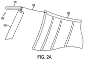
- the tear straps 106 may be positioned on the corners, or other positions, of the net 102 to improve capture geometry and to reduce the initial structural shock impulse, i.e. to attenuate the initial peal load.
- the tear straps 106 may be positioned between ropes or lanyards 108 holding the corners of the net 102 and the ends of each net pole 104', 104".
- the tear straps 106 Prior to capture, the tear straps 106 are embodied in a retracted position 106' and, for example, may comprise Nylon, or other material, doubled-over straps sewn together down the center of the strap with a thin sewing thread. In the retracted position 106', the tear straps 106 may provide additional slack to the net 102 to attenuate the impact force as the aircraft wings initially hit the net 102.
- the tear straps 106 may shift from the retracted position 106' into a released position 106", as shown in FIG. 2B .
- This may occur, for example, when the sewing thread of the tear strap 106 registers a certain force, for example, a force of approximately 50 lbs, that is associated with the impact of the aircraft on the net 102, and breaks; ripping the seam holding the tear strap 106 in the retracted position 106'.
- the breaking of the sewing thread allows the force of the impact to pull the tear strap 106 in retracted position 106' fully or partially straight into the released position 106", as seen in FIG. 2B .
- This causes the tear straps 106 to change the angle of the net to improve capture of the aircraft.
- the straps tear they smoothly accelerate the pivot arms thus avoiding a rapid acceleration similar to an impact that would occur without these devices.
- other energy elements may be used, such as, for example, slip devices, Velcro® or shock absorbers. After use, the energy elements may either be reused or replaced.
- the pole pairs 104 are held in place by two hydraulically erectable arm assemblies 110 joined to a central shaft, called the recovery pivot beam 112.
- Each arm assembly 110 includes a vertical beam 114, a corner beam 116 and a diagonal beam 118.
- the vertical beam 114 is coupled to the pole pair 104.
- the diagonal beam 118 is connected to the recovery pivot beam 112.
- the corner beam 116 serves to connect the vertical beam 114 to the diagonal beam 118.
- the mobile aircraft recovery system 100 may include one or more shear devices 120, such as a shear pins, nylon ties, or the like, which hold the net in the ready to capture position prior to recovery.
- the shear devices 120 maintain an open net 102 by holding the lower net pole 104" in a certain position relative to the arm assembly 110. This prevents the pole pairs 104 from prematurely pivoting, for example, due to wind or other external forces.
- the shear devices 120 release allowing the pole pairs 104 to gain their initial momentum forward.
- the shear devices 120 may be replaced after each recovery.
- the mobile aircraft recovery system 100 may include one or more shock absorption devices 122 positioned to absorb energy upon impact of the aircraft 300.
- the shock absorption devices 122 may be coupled to the top of vertical beam 114.
- the shock absorption devices 122 may also be coupled to the pole pairs 104 and may provide the pivot point for each pole pair 104.
- the shock absorption devices 122 may be, for example, friction dampers or brakes, rotary shock absorbers or dampers, or linear dampers. Such shock absorption devices 122 may help slow the aircraft and bring the aircraft to rest in the net.
- the pivot of the whole structure of the mobile aircraft recovery system 100 helps keep the aircraft from swinging.
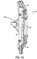
- FIG. 1A depicts a rear detailed view of a shock absorption device 122, as shown in FIG. 1 .
- the shock absorption device 122 includes a vertical bar 125 which may be coupled to the vertical beam 114 of the arm assembly 110.
- a sliding mechanism 127 may be coupled to the vertical bar 125 to control the pivoting movement of the pole pair 104. Coupled to the sliding mechanism 127 are two dampers 123 to absorb the shock of the impact of the aircraft in the net 102.
- the dampers 123 may be friction, rotary or linear dampers.
- Pole levers 124 may be further coupled to each end of the sliding mechanism 127 and are able to attach to the ends of the top and bottom net poles 104', 104".
- each shock absorption device 122 may include the timing or kinematic mechanism which, as previously discussed, facilitates the synchronous movement of the top and bottom net poles 104', 104".
- the timing mechanism enables the pole levers 124 of the top and bottom net poles 104', 104" to move at the same time.
- the synchronous movement of the pole pairs 104 when combined with the energy elements 106, forms the net 102 into a basket configuration which cradles the aircraft upon impact. Non-synchronous movement of the pole pairs 104 may cause the net 102 to remain in the flat ready to capture position, causing the aircraft to fall or bounce out of the net 102.
- the mobile aircraft recovery system 100 includes a hydraulic activation system 126, including the recovery pivot beam 112, a recovery actuator 128 and a recovery base 130, for raising and lowering the arm assemblies 110 and net 102.
- the hydraulic activation system 126 may also include a hydraulic cushion (not shown).
- the hydraulic cushion may include hydraulic valves and gas accumulators that are separate from the raising and lowering actuation function that permits the actuator to move passively in the direction of recovery. The motion is permitted because the valves cause oil holding the actuator in the upright position to flow into the gas accumulator.
- the recovery pivot beam 112 of the hydraulic activation system 126 allows the diagonal beams 118 of the arm assemblies 110 to fall or pivot forward during the capture of the aircraft to further help dissipate the momentum of the aircraft.
- FIG. 4 depicts a side view of the mobile aircraft recovery system during impact of the aircraft.
- Angle ⁇ shows the change in position of the diagonal beam 118 forward from a starting position along axis A (see FIG. 3A ), that is perpendicular to the ground.
- FIG. 3A depicts a side view of the mobile aircraft recovery system 100 prior to impact of the aircraft 300, according to an embodiment of the present invention.
- the vertical beam 114 of the arm assembly 110 is positioned along a perpendicular axis A relative to the ground.
- the top net poles 104' Prior to impact of the aircraft 300, are positioned at a pre-determined angle ⁇ 1 relative to axis A and the bottom net poles 104" are positioned at a predetermined angle ⁇ 11 relative to axis A.
- the predetermined angles ⁇ 1 and ⁇ 11 of the net poles 104', 104" are selected to ensure that the net 102 remains in the ready to capture position prior to impact. According to one embodiment, angle ⁇ 1 is approximately equal to angle ⁇ 11 .
- angles ⁇ 1 and ⁇ 11 of the net poles 104', 104" are both less than 45 degrees. Further, the tear strips 106 remain in their initial retracted position 106', which aids in pulling the net 102 close to each of the top and bottom net poles 104', 104" and in ready to capture position.
- shear devices 120 may be used maintain the angles ⁇ 11 between the bottom net poles 104" and the vertical beam 114 prior to impact. Because each bottom net pole 104" moves in synchronization with its respective top net pole 104', maintaining the angle ⁇ 11 of the bottom net pole 104" using a shear device 120 simultaneously maintains the angle ⁇ 1 of the top net pole 104'. The shear devices 120 prevent wind or any other external force from inadvertently interfering with the recovery of the aircraft 300.
- FIG. 3B depicts a side view of the mobile aircraft recovery system 100 during impact of the aircraft 300, according to an embodiment of the present invention.
- the force of impact releases the shear device 120 and causes the pole pairs 104 to each pivot about their pivot points forward in the direction of impact D.
- the pivoting momentum of the pole pairs 104 allows the net 102 to form a basket-like configuration to envelop and capture the aircraft 300.
- the energy absorbing devices 122, i.e. the dampers, attached to the pole pairs 104 help bring the aircraft 300 to rest in the net 102.
- the angles ⁇ 1 and ⁇ 11 of the top and bottom net poles 104', 104" respectively, increase to angles ⁇ 2 and ⁇ 22 relative to the perpendicular axis A defined by the vertical beam 114 of the arm assembly 110.
- the angle ⁇ 2 of the top net pole 104' increases more than the angle ⁇ 22 of the bottom net pole 104" during capture.
- the release of the tear straps 106 i.e. the straightening out of the retracted position 106', may occur in the direction N of the net 102 (See FIG. 2B ).
- the release of the tear straps 106 may also transform the net 102 from the ready to capture position, as depicted in FIG. 3A , into the basket-like configuration, as depicted in FIG. 3B .
- the top net poles 104' are loaded similarly to the bottom net poles 104", however the tear straps 106 are rated lower and are longer on the top than on the bottom. This ensures to improve the basket-like configuration of the net 102.
- the top tear straps 106 may tear all the way and, since they are longer, they compensate for the top poles being higher.
- pole pairs 104 and net 102 are lowered using the hydraulic actuator 128 and the aircraft 300 may be manually removed from the net by a ground crew.
- FIG. 3C depicts a side view of the mobile aircraft recovery system 100 after impact of the aircraft 300, according to an embodiment of the present invention.
- the aircraft 300 has been captured and has come to rest in the net 102.
- the top and bottom net poles 104', 104" have similarly come to rest at angles ⁇ 3 and ⁇ 33 , respectively, relative to the vertical beam 114.
- FIG. 4 depicts a side view of the mobile aircraft recovery system 100 during impact of the aircraft 300, according to an alternative embodiment of the present invention.
- this initial impact force causes each arm assembly 110 to pivot forward on the recovery pivot beam 112 (see FIG. 1 ).
- the arm assembly 110 has pivoted away from the perpendicular axis A in the direction of impact D by an angle ⁇ . This additional movement of the arm assemblies 100 helps further dissipate the momentum of the aircraft 300 during capture.
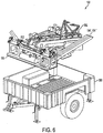
- FIGS. 5 and 6 depict an exploded view of the mobile aircraft recovery unit 100 in a stowed position, according to an embodiment of the present invention.
- the mobile aircraft recovery unit 100 comprises a modular design to permit disassembly for compact storage when not in use.
- the recovery base 130 may house the disassembled net poles 104', 104", the recovery pilot beam 112, the vertical beams 114, the corner beams 116, the diagonal beams 118 and the recovery actuator 128.
- the recovery base 130 may fit into a mobile unit 500, for example a trailer assembly.
- a launcher assembly 502 may be coupled to the recovery base 130 of the mobile unit 500 to launch the aircraft 300.
- the net 102, tear straps 106, hand control unit (see control unit 700 below), electrical cables and other equipment may be transported within the mobile unit 500 in transit cases (not shown).
- FIG. 7 depicts a front view of a control unit 700 of the mobile aircraft recovery system 100, according to an exemplary embodiment of the present invention.
- the control unit 700 may control both the mobile aircraft recovery system 100, as well as the launch system.
- the control unit 700 may include a mode switch 702 to switch between "off,” “standby,” “launch,” and “net” modes.
- the control unit 700 may include a net position switch 704 for lifting or lowering the position of the net 102 using the hydraulic activation system 126.
- control unit 700 may include a net cushion switch 706 for adjusting the pre-determined angle ⁇ of the arm assembly 110 relative to the perpendicular axis A to ensure that the net 102 remains in the ready to capture position prior to impact of the aircraft 300 on the net 102.
- the control unit 700 may include one or more indicators 708 to indicate, for example, that the mobile aircraft recovery system 100 or launch assembly 502 is safe to operate, that the hydraulic activation system 126 of the mobile aircraft recovery system 100 is ready to pressurize, or that the launch assembly 502 is ready to launch the aircraft 300.
- the control unit 700 may further include, for example, a hydraulic power unit (HPU) switch 710 to activate the hydraulic activation system 126 for either recovery operation or launch, a pressurize switch 712 to pressurize the hydraulic activation system 126 and/or a launch switch 714 to launch the aircraft using the launch assembly 502.
- HPU hydraulic power unit
- the mobile aircraft recovery system 100 may be embodied as a passive capture system, where no electronics or computers are required.
- switch logic may be used without the use of computers or software.
- Embodiments of the mobile aircraft recovery system 100 enjoy several advantages over other systems known in the art.
- the mobile aircraft recovery system 100 can be mobilized on land or on a ship deck with a single trailer and does not require the use of separate supporting structures or anchors.
- One exception is the use of the mobile aircraft recovery system 100 on a ship deck during a high sea state, where tie-downs are required for all deck equipment.
- the small footprint of the mobile aircraft recovery system 100 allows for easy ship integration, including minimal modification and interference with current operations, also known as normal operations on the flight deck or "OPS.” Because the mobile aircraft recovery system 100 may be added to an existing ship, it is important that the system does not interfere with existing operational procedure and business.
- the mobile aircraft recovery system 100 is further able to withstand ship motion having pitch, heave and roll tolerance, as well as navigation sensitivity.
- the mobile aircraft recovery system 100 is quick and easy to both assemble and disassemble.
- the mobile aircraft recovery system 100 does not require a unique configuration of the aircraft 300 due to the basket-like configuration of the net 102 which supports a soft impact on the aircraft wings.
- the aircraft 300 does not require the use of strengthening devices in the aircraft's wings to support the capture, as is known in the prior art.
- the soft landing enabled by the mobile aircraft recovery system 100 has a minimal impact on the aircraft 300 weight since flight loads are the driving consideration for structural sizing. Only minor wing leading edge enhancement may be required with minimal weigh impact on the aircraft.
- the mobile aircraft recovery system 100 may be sized to work accurately with existing aircraft navigation systems and may be combined with a launcher assembly 502, as described above.
- the mobile aircraft recovery system 100 is both compact and transportable, as well as reliable and durable during use.
- the mobile aircraft recovery system 100 is cost efficient in both the development and production stages.
Landscapes
- Engineering & Computer Science (AREA)
- Aviation & Aerospace Engineering (AREA)
- General Engineering & Computer Science (AREA)
- Mechanical Engineering (AREA)
- Remote Sensing (AREA)
- Radar, Positioning & Navigation (AREA)
- Physics & Mathematics (AREA)
- Acoustics & Sound (AREA)
- Vibration Dampers (AREA)
- Devices Affording Protection Of Roads Or Walls For Sound Insulation (AREA)
- Control Of Position, Course, Altitude, Or Attitude Of Moving Bodies (AREA)
Description
- Embodiments of the present invention relate generally to new and useful improvements in mobile aircraft recovery, and more particularly to an apparatus and method for the capture of aircraft, including unmanned aerial vehicles (UAVs), drones, and other flight devices or projectiles.
- The recovery of aircraft without the use of a runway is generally known in the art. See, for example, the "skyhook" approach, as disclosed in
U.S. Patent Nos. 7,090,166 ,7,104,495 ,7,114,680 and Pre-Grant Publication Nos.2005/0151009 and2005/0178894 , where a boom from a ship or other vehicle is extendable to deploy a recovery line to capture the aircraft in flight. The skyhook approach requires that the leading edge of the aircraft wing be strong enough to survive the wire impact on the recovery line. Thus, the aircraft structure is heavy, resulting in a negative impact on aircraft payload capacity and endurance. Other approaches, such as the arresting hook inU.S. Patent No. 7,143,976 to Snediker et al. , or the deployable lifting device inU.S. Patent No. 4,753,400 to Reuter et al. , share similar problems. - In short, there exists a need in the art for a mobile aircraft recovery system that is able to limit damage to the aircraft during recovery using a lighter aircraft and, thus, minimizing, the impact on aircraft endurance. A further need exists for a mobile aircraft recovery system that is itself small and lightweight so as to be mobile, versatile on land and sea, and transportable. Additionally, a need exists for a mobile aircraft recovery system having a strong wind tolerance, including tolerance of wind variation, direction and speed.
- The invention is defined by the technical features set forth in claim 1.Optional features are disclosed in the dependent claims. In an embodiment, an apparatus for the recovery of an aircraft includes a capture device and a first and second pole pair. The first pole pair includes first top and bottom poles respectively placed near first top and bottom portions of the capture device. The first pole pair is configured to move from a first position, in which the pole pair holds the capture device in an open position to capture the aircraft, to a second position, in which the pole pair holds the capture device in a closed position to contain the captured aircraft after impact of the aircraft on the capture device. The second pole pair includes second top and bottom poles respectively placed near second top and bottom portions of the capture device. The second pole pair is also configured to move from the first position to the second position. The apparatus further includes energy elements each coupled on one end to a respective top or bottom portion of the capture device and on another end to a respective top or bottom pole. The energy elements are disposed to absorb the force of the impact.
- According to one exemplary embodiment, the first pole pair comprising first top and bottom poles may be coupled at first ends to a first support beam, the top and bottom poles extending to first top and bottom portions of the capture device. Similarly, the second pole pair comprising second top and bottom poles may be coupled at first ends to a second support beam, the top and bottom poles extending to second top and bottom portions of the capture device. Further, a pivot beam may be coupled to each of the first and second support beams, wherein the pivot beam is disposed to pivot each of the first and second support beams forward in the direction of the impact of the aircraft.
- In another embodiment, a method for the recovery of an aircraft includes coupling a first pole pair comprising first top and bottom poles respectively to first top and bottom positions of a capture device and coupling a second pole pair comprising second top and bottom poles respectively to second top and bottom positions of the capture device. The method further includes moving each pole pair from a first position, in which the pole pairs hold the capture device in an open position to capture the aircraft, to a second position, in which the pole pairs hold the capture device in a closed position to contain the captured aircraft. The method includes absorbing a force of the impact using energy elements, each coupled on one end to a respective top or bottom position of the capture device and on another end to a respective top or bottom pole.
- According to a further embodiment, the method includes pivoting the first and second pole pairs forward in the direction of the impact.
- This summary is provided merely to introduce certain concepts and not to identify any key or essential features of the claimed subject matter. Further features and advantages of embodiments of the invention, as well as the structure and operation of various embodiments of the invention, are described in detail below with reference to the accompanying drawings.
- The foregoing and other features and advantages of embodiments of the invention will be apparent from the following, more particular description of embodiments of the invention, as illustrated in the accompanying drawings wherein like reference numbers generally indicate identical, functionally similar, and/or structurally similar elements. Unless otherwise indicated, the accompanying drawing figures are not to scale.
-
FIG. 1 depicts a perspective view of the mobile aircraft recovery system according to an embodiment of the present invention; -
FIG. 1A depicts a rear detailed view of the shock absorption device of the mobile aircraft recovery system, as shown inFIG. 1 -
FIGS. 2A and2B depict a detailed view of the tear straps of the mobile aircraft recovery system as shown inFIG. 1 ; -
FIG. 3A depicts a side view of the mobile aircraft recovery system prior to impact of the aircraft, according to an embodiment of the present invention; -
FIG. 3B depicts a side view of the mobile aircraft recovery system during impact of the aircraft, according to an embodiment of the present invention; -
FIG. 3C depicts a side view of the mobile aircraft recovery system after impact of the aircraft, according to an embodiment of the present invention; -
FIG. 4 depicts a side view of the mobile aircraft recovery system during impact of the aircraft, according to an alternative embodiment of the present invention -
FIGS. 5 and6 depict an exploded view of the mobile recovery unit in a stowed position, according to an embodiment of the present invention; and -
FIG. 7 depicts a front view of a control unit of the mobile aircraft recovery system, according to an embodiment of the present invention. - Referring now to the drawings, there is shown in
FIG. 1 a perspective view of the mobileaircraft recovery system 100 according to an embodiment of the present invention. Acapture device 102, for example, a net, sits in an open vertical position above the ground prior to the capture of an aircraft. The vertical position of the net 102 may be referred to as a "ready to capture position." The net 102 is shaped to focus the deceleration loads on the aircraft wing closest to the fuselage, thus avoiding wing tip bending. For example, according to one embodiment, the net 102 may be a ribbon net or other net which forms a basket shape, expanding outward to cradle the aircraft during capture. The use of a basket-shaped net retains the aircraft after impact and prevents the aircraft from falling out of the net or springing backwards off the net 102 and incurring damage. - The net 102 is supported, for example, by two
pole pairs 104. Thepole pairs 104 of the mobileaircraft recovery system 100 are used to absorb the momentum of the aircraft during capture. Eachpole pair 104 may include an upper net pole 104' coupled to an upper portion of thenet 102 and alower net pole 104" coupled to a bottom portion of thenet 102. In the embodiment shown, thepoles 104', 104" are coupled to corners of thenet 102. Eachnet pole 104', 104" may rotate about a pivot point located at an opposite end of therespective net pole 104', 104" from thenet 102. Further, the upper and lowernet poles 104', 104" of eachpole pair 104 may move in synchronization relative to one another. - The initial impact of the aircraft on the
net 102 engages the pivoting movement of thepole pairs 104. A timing or kinematic mechanism may be coupled to eachpole pair 104 to help synchronize the movement of the top andbottom net poles 104', 104" together. Such synchronization allows the net 102 andpole pairs 104 capture an aircraft 300 (seeFIG. 3A ) by folding around the primary aircraft wing to decelerate the aircraft while engulfing the aircraft for post deceleration retention. - According to one embodiment, the net 102 and
pole pairs 104 may be coupled usingenergy elements 106, i.e. tear straps. Thetear straps 106 may be positioned on the corners, or other positions, of thenet 102 to improve capture geometry and to reduce the initial structural shock impulse, i.e. to attenuate the initial peal load. As seen inFIG. 2A , the tear straps 106 may be positioned between ropes orlanyards 108 holding the corners of the net 102 and the ends of eachnet pole 104', 104". Prior to capture, the tear straps 106 are embodied in a retracted position 106' and, for example, may comprise Nylon, or other material, doubled-over straps sewn together down the center of the strap with a thin sewing thread. In the retracted position 106', the tear straps 106 may provide additional slack to the net 102 to attenuate the impact force as the aircraft wings initially hit the net 102. - Following the impact of the
aircraft 300 on the net 102, the tear straps 106 may shift from the retracted position 106' into a releasedposition 106", as shown inFIG. 2B . This may occur, for example, when the sewing thread of thetear strap 106 registers a certain force, for example, a force of approximately 50 lbs, that is associated with the impact of the aircraft on the net 102, and breaks; ripping the seam holding thetear strap 106 in the retracted position 106'. Thus, the breaking of the sewing thread allows the force of the impact to pull thetear strap 106 in retracted position 106' fully or partially straight into the releasedposition 106", as seen inFIG. 2B . This causes the tear straps 106 to change the angle of the net to improve capture of the aircraft. As the straps tear they smoothly accelerate the pivot arms thus avoiding a rapid acceleration similar to an impact that would occur without these devices. Alternatively, other energy elements may be used, such as, for example, slip devices, Velcro® or shock absorbers. After use, the energy elements may either be reused or replaced. - According to the embodiment shown in
Figure 1 , the pole pairs 104 are held in place by two hydraulicallyerectable arm assemblies 110 joined to a central shaft, called therecovery pivot beam 112. Eacharm assembly 110 includes avertical beam 114, acorner beam 116 and adiagonal beam 118. On one end of thearm assembly 110, thevertical beam 114 is coupled to thepole pair 104. On the other end of thearm assembly 110, thediagonal beam 118 is connected to therecovery pivot beam 112. Thecorner beam 116 serves to connect thevertical beam 114 to thediagonal beam 118. - According to one embodiment, the mobile
aircraft recovery system 100 may include one ormore shear devices 120, such as a shear pins, nylon ties, or the like, which hold the net in the ready to capture position prior to recovery. Specifically, theshear devices 120 maintain anopen net 102 by holding the lowernet pole 104" in a certain position relative to thearm assembly 110. This prevents the pole pairs 104 from prematurely pivoting, for example, due to wind or other external forces. When a certain force that is associated with the impact of the aircraft on the net 102 is registered by theshear device 120, theshear devices 120 release allowing the pole pairs 104 to gain their initial momentum forward. Theshear devices 120 may be replaced after each recovery. - According to another embodiment, the mobile
aircraft recovery system 100 may include one or moreshock absorption devices 122 positioned to absorb energy upon impact of theaircraft 300. As shown inFIG. 1 , theshock absorption devices 122 may be coupled to the top ofvertical beam 114. Theshock absorption devices 122 may also be coupled to the pole pairs 104 and may provide the pivot point for eachpole pair 104. Theshock absorption devices 122 may be, for example, friction dampers or brakes, rotary shock absorbers or dampers, or linear dampers. Suchshock absorption devices 122 may help slow the aircraft and bring the aircraft to rest in the net. The pivot of the whole structure of the mobileaircraft recovery system 100 helps keep the aircraft from swinging. -
FIG. 1A depicts a rear detailed view of ashock absorption device 122, as shown inFIG. 1 . According to one embodiment, theshock absorption device 122 includes avertical bar 125 which may be coupled to thevertical beam 114 of thearm assembly 110. A slidingmechanism 127 may be coupled to thevertical bar 125 to control the pivoting movement of thepole pair 104. Coupled to the slidingmechanism 127 are twodampers 123 to absorb the shock of the impact of the aircraft in the net 102. As described above, thedampers 123 may be friction, rotary or linear dampers. Pole levers 124 may be further coupled to each end of the slidingmechanism 127 and are able to attach to the ends of the top and bottomnet poles 104', 104". - According to a further embodiment, each
shock absorption device 122 may include the timing or kinematic mechanism which, as previously discussed, facilitates the synchronous movement of the top and bottomnet poles 104', 104". The timing mechanism enables the pole levers 124 of the top and bottomnet poles 104', 104" to move at the same time. The synchronous movement of the pole pairs 104, when combined with theenergy elements 106, forms the net 102 into a basket configuration which cradles the aircraft upon impact. Non-synchronous movement of the pole pairs 104 may cause the net 102 to remain in the flat ready to capture position, causing the aircraft to fall or bounce out of the net 102. - According to a further embodiment, the mobile
aircraft recovery system 100 includes ahydraulic activation system 126, including therecovery pivot beam 112, arecovery actuator 128 and arecovery base 130, for raising and lowering thearm assemblies 110 andnet 102. Thehydraulic activation system 126 may also include a hydraulic cushion (not shown). For example, the hydraulic cushion may include hydraulic valves and gas accumulators that are separate from the raising and lowering actuation function that permits the actuator to move passively in the direction of recovery. The motion is permitted because the valves cause oil holding the actuator in the upright position to flow into the gas accumulator. According to one embodiment, therecovery pivot beam 112 of thehydraulic activation system 126 allows thediagonal beams 118 of thearm assemblies 110 to fall or pivot forward during the capture of the aircraft to further help dissipate the momentum of the aircraft. This is shown inFIG. 4 , which depicts a side view of the mobile aircraft recovery system during impact of the aircraft. Angle α shows the change in position of thediagonal beam 118 forward from a starting position along axis A (seeFIG. 3A ), that is perpendicular to the ground. -
FIG. 3A depicts a side view of the mobileaircraft recovery system 100 prior to impact of theaircraft 300, according to an embodiment of the present invention. Thevertical beam 114 of thearm assembly 110 is positioned along a perpendicular axis A relative to the ground. Prior to impact of theaircraft 300, the top net poles 104' are positioned at a pre-determined angle θ1 relative to axis A and the bottomnet poles 104" are positioned at a predetermined angle θ11 relative to axis A. The predetermined angles θ1 and θ11 of thenet poles 104', 104" are selected to ensure that the net 102 remains in the ready to capture position prior to impact. According to one embodiment, angle θ1 is approximately equal to angle θ11. According to another embodiment, angles θ1 and θ11 of thenet poles 104', 104" are both less than 45 degrees. Further, the tear strips 106 remain in their initial retracted position 106', which aids in pulling the net 102 close to each of the top and bottomnet poles 104', 104" and in ready to capture position. - As discussed above,
shear devices 120 may be used maintain the angles θ11 between the bottomnet poles 104" and thevertical beam 114 prior to impact. Because each bottomnet pole 104" moves in synchronization with its respective top net pole 104', maintaining the angle θ11 of the bottomnet pole 104" using ashear device 120 simultaneously maintains the angle θ1 of the top net pole 104'. Theshear devices 120 prevent wind or any other external force from inadvertently interfering with the recovery of theaircraft 300. -
FIG. 3B depicts a side view of the mobileaircraft recovery system 100 during impact of theaircraft 300, according to an embodiment of the present invention. As theaircraft 300 strikes the net 102, the force of impact releases theshear device 120 and causes the pole pairs 104 to each pivot about their pivot points forward in the direction of impact D. The pivoting momentum of the pole pairs 104, allows the net 102 to form a basket-like configuration to envelop and capture theaircraft 300. Theenergy absorbing devices 122, i.e. the dampers, attached to the pole pairs 104 help bring theaircraft 300 to rest in the net 102. - As the pole pairs 104 pivot forward the angles θ1 and θ11 of the top and bottom
net poles 104', 104", respectively, increase to angles θ2 and θ22 relative to the perpendicular axis A defined by thevertical beam 114 of thearm assembly 110. According to one embodiment, the angle θ2 of the top net pole 104' increases more than the angle θ22 of the bottomnet pole 104" during capture. - Furthermore, the impact of the
aircraft 300 on the net 102, as well as the pivoting motion of the pole pairs 104, causes the tear straps 106 to pull from the retracted position 106' into the releasedposition 106". The release of the tear straps 106, i.e. the straightening out of the retracted position 106', may occur in the direction N of the net 102 (SeeFIG. 2B ). The release of the tear straps 106 may also transform the net 102 from the ready to capture position, as depicted inFIG. 3A , into the basket-like configuration, as depicted inFIG. 3B . - According to one embodiment, the top net poles 104' are loaded similarly to the bottom
net poles 104", however the tear straps 106 are rated lower and are longer on the top than on the bottom. This ensures to improve the basket-like configuration of the net 102. Thetop tear straps 106 may tear all the way and, since they are longer, they compensate for the top poles being higher. - After recovery, the pole pairs 104 and net 102 are lowered using the
hydraulic actuator 128 and theaircraft 300 may be manually removed from the net by a ground crew. -
FIG. 3C depicts a side view of the mobileaircraft recovery system 100 after impact of theaircraft 300, according to an embodiment of the present invention. In this embodiment, theaircraft 300 has been captured and has come to rest in the net 102. The top and bottomnet poles 104', 104" have similarly come to rest at angles θ3 and θ33, respectively, relative to thevertical beam 114. -
FIG. 4 depicts a side view of the mobileaircraft recovery system 100 during impact of theaircraft 300, according to an alternative embodiment of the present invention. In addition to that described inFIG. 3B , in this alternative embodiment, as theaircraft 300 first strikes the net 102, this initial impact force causes eacharm assembly 110 to pivot forward on the recovery pivot beam 112 (seeFIG. 1 ). As seen inFIG. 4 , thearm assembly 110 has pivoted away from the perpendicular axis A in the direction of impact D by an angle α. This additional movement of thearm assemblies 100 helps further dissipate the momentum of theaircraft 300 during capture. -
FIGS. 5 and6 depict an exploded view of the mobileaircraft recovery unit 100 in a stowed position, according to an embodiment of the present invention. As shown, the mobileaircraft recovery unit 100 comprises a modular design to permit disassembly for compact storage when not in use. Specifically, therecovery base 130 may house the disassemblednet poles 104', 104", therecovery pilot beam 112, thevertical beams 114, the corner beams 116, thediagonal beams 118 and therecovery actuator 128. Therecovery base 130 may fit into amobile unit 500, for example a trailer assembly. According to one embodiment, alauncher assembly 502 may be coupled to therecovery base 130 of themobile unit 500 to launch theaircraft 300. - Additionally, the net 102, tear straps 106, hand control unit (see
control unit 700 below), electrical cables and other equipment may be transported within themobile unit 500 in transit cases (not shown). -
FIG. 7 depicts a front view of acontrol unit 700 of the mobileaircraft recovery system 100, according to an exemplary embodiment of the present invention. According to one embodiment, thecontrol unit 700 may control both the mobileaircraft recovery system 100, as well as the launch system. Thecontrol unit 700 may include amode switch 702 to switch between "off," "standby," "launch," and "net" modes. Thecontrol unit 700 may include anet position switch 704 for lifting or lowering the position of the net 102 using thehydraulic activation system 126. Further, thecontrol unit 700 may include anet cushion switch 706 for adjusting the pre-determined angle α of thearm assembly 110 relative to the perpendicular axis A to ensure that the net 102 remains in the ready to capture position prior to impact of theaircraft 300 on the net 102. - The
control unit 700 may include one ormore indicators 708 to indicate, for example, that the mobileaircraft recovery system 100 or launchassembly 502 is safe to operate, that thehydraulic activation system 126 of the mobileaircraft recovery system 100 is ready to pressurize, or that thelaunch assembly 502 is ready to launch theaircraft 300. Thecontrol unit 700 may further include, for example, a hydraulic power unit (HPU)switch 710 to activate thehydraulic activation system 126 for either recovery operation or launch, apressurize switch 712 to pressurize thehydraulic activation system 126 and/or alaunch switch 714 to launch the aircraft using thelaunch assembly 502. - Alternatively, the mobile
aircraft recovery system 100 may be embodied as a passive capture system, where no electronics or computers are required. For example, switch logic may be used without the use of computers or software. - Embodiments of the mobile
aircraft recovery system 100 enjoy several advantages over other systems known in the art. The mobileaircraft recovery system 100 can be mobilized on land or on a ship deck with a single trailer and does not require the use of separate supporting structures or anchors. One exception is the use of the mobileaircraft recovery system 100 on a ship deck during a high sea state, where tie-downs are required for all deck equipment. The small footprint of the mobileaircraft recovery system 100 allows for easy ship integration, including minimal modification and interference with current operations, also known as normal operations on the flight deck or "OPS." Because the mobileaircraft recovery system 100 may be added to an existing ship, it is important that the system does not interfere with existing operational procedure and business. The mobileaircraft recovery system 100 is further able to withstand ship motion having pitch, heave and roll tolerance, as well as navigation sensitivity. - The mobile
aircraft recovery system 100 is quick and easy to both assemble and disassemble. The mobileaircraft recovery system 100 does not require a unique configuration of theaircraft 300 due to the basket-like configuration of the net 102 which supports a soft impact on the aircraft wings. For example, theaircraft 300 does not require the use of strengthening devices in the aircraft's wings to support the capture, as is known in the prior art. Similarly the soft landing enabled by the mobileaircraft recovery system 100 has a minimal impact on theaircraft 300 weight since flight loads are the driving consideration for structural sizing. Only minor wing leading edge enhancement may be required with minimal weigh impact on the aircraft. - The mobile
aircraft recovery system 100 may be sized to work accurately with existing aircraft navigation systems and may be combined with alauncher assembly 502, as described above. The mobileaircraft recovery system 100 is both compact and transportable, as well as reliable and durable during use. The mobileaircraft recovery system 100 is cost efficient in both the development and production stages. - It will be understood that the above description of the present invention is susceptible to various modifications, changes and adaptations, and that the same are intended to be comprehended within the meaning and range of equivalents of the appended claims.
Claims (12)
- An apparatus for the recovery of an aircraft, comprisinga capture device (102);a first pole pair (104) comprising first top and bottom poles (104', 104") respectively placed near first top and bottom portions of the capture device (102), wherein the first pole pair (104) is configured to move from a first position, in which the pole pair (104) holds the capture device (102) in an open position to capture the aircraft, to a second position, in which the pole pair holds the capture device (102) in a closed position to contain the captured aircraft after impact of the aircraft on the capture device (102);a second pole pair (104) comprising second top and bottom poles (104', 104") respectively placed near second top and bottom portions of the capture device (102), wherein the second pole pair (104) is also configured to move from the first position to the second position;wherein each pole (104', 104") may rotate about the pivot point located at an opposite end of the respective pole (104', 104") from the net (102); characterized in that energy elements (106) each coupled on one end to a respective top or bottom portion of the capture device (102) and on another end to a respective top or bottom pole (104', 104"), wherein the energy elements (106) are disposed to absorb the force of the impact of the aircraft.
- The apparatus of claim 1, characterized in that the top and bottom poles of each pole pair (104) are pivotable with respect to one another.
- The apparatus of any of claims 1-2, characterized in that it comprises shock absorption devices (122) each coupled to a respective one of the first and second pole pairs (104).
- The apparatus of claim 3, characterized in that the shock absorption devices (122) comprise at least one of a linear damper, a friction damper or a rotary damper.
- The apparatus of any of claims 1-4, characterized in that the apparatus further comprises synchronization devices each coupled to one of the first and second pole pairs (104) to synchronize the movement of the top and bottom poles, respectively.
- The apparatus of any of claims 1-5, characterized in that the capture device (102) comprises a ribbon net that forms a basket-like configuration to cradle the aircraft after impact on the net.
- The apparatus of any of claims 1-6, characterized in that the apparatus further comprises:beams (112), each coupled to one of the first and second pole pairs (104) on ends opposite from the capture device (102); andshear devices (120) that couple the first and second bottom poles to each respective beam to maintain the apparatus in an open position prior to the impact of the aircraft on the capture device (102).
- The apparatus of claim 7, characterized in that the shear devices (120) comprise one of shear pins or nylon ties.
- An apparatus of any of claims 1-8, characterized in that the apparatus comprisesthe first pole pair (104) comprising the first top and bottom poles coupled at first ends to a first support beam, the top and bottom poles respectively extending to the first top and bottom portions of the capture device (102);the second pole pair (104) comprising the second top and bottom poles coupled at first ends to a second support beam, the top and bottom poles respectively extending to the second top and bottom portions of the capture device (102); anda pivot beam (112) coupled to each of the first and second support beams, wherein the pivot beam (112) is disposed to pivot each of the first and second support beams in the direction of the impact of the aircraft;.
- A mobile recovery unit (100), characterized in that the mobile recovery unit comprises a transportable construction to house the elements of any of claims 1-9.
- A method for the recovery of an aircraft, characterized in that the method comprises:coupling a first pole pair (104) comprising first top and bottom poles respectively to first top and bottom positions of a capture device (102);coupling a second pole pair (104) comprising second top and bottom poles respectively to second top and bottom positions of the capture device (102);moving each pole pair (104) from a first position, in which the pole pairs hold the capture device (102) in an open position to capture the aircraft, to a second position, in which the pole pairs (104) hold the capture device (102) in a closed position to contain the captured aircraft;wherein each pole (104', 104") may rotate about the pivot point located at an opposite end of the respective pole (104', 104") from the net (102); andabsorbing the force of the impact using energy elements (106), each coupled on one end to a respective top or bottom position of the capture device (102) and on another end to a respective top or bottom pole (104', 104").
- A method for the recovery of an aircraft of claim 11, characterized in that the method comprises:pivoting the coupled first and second pole pairs (104) forward in the direction of the impact.
Applications Claiming Priority (2)
| Application Number | Priority Date | Filing Date | Title |
|---|---|---|---|
| US12/796,950 US8453967B2 (en) | 2010-06-09 | 2010-06-09 | Mobile aircraft recovery system |
| PCT/US2011/034962 WO2011156062A1 (en) | 2010-06-09 | 2011-05-03 | Mobile aircraft recovery system |
Publications (3)
| Publication Number | Publication Date |
|---|---|
| EP2580117A1 EP2580117A1 (en) | 2013-04-17 |
| EP2580117A4 EP2580117A4 (en) | 2014-10-08 |
| EP2580117B1 true EP2580117B1 (en) | 2018-04-18 |
Family
ID=45095447
Family Applications (1)
| Application Number | Title | Priority Date | Filing Date |
|---|---|---|---|
| EP11792831.7A Active EP2580117B1 (en) | 2010-06-09 | 2011-05-03 | Mobile aircraft recovery system |
Country Status (9)
| Country | Link |
|---|---|
| US (1) | US8453967B2 (en) |
| EP (1) | EP2580117B1 (en) |
| KR (1) | KR101831679B1 (en) |
| AU (1) | AU2011264627B2 (en) |
| BR (1) | BR112012031188A2 (en) |
| CA (1) | CA2802146C (en) |
| IL (1) | IL223182A (en) |
| PT (1) | PT2580117T (en) |
| WO (1) | WO2011156062A1 (en) |
Families Citing this family (36)
| Publication number | Priority date | Publication date | Assignee | Title |
|---|---|---|---|---|
| US9085362B1 (en) | 2012-11-21 | 2015-07-21 | Lockheed Martin Corporation | Counter-unmanned aerial vehicle system and method |
| US9862503B2 (en) * | 2013-09-16 | 2018-01-09 | Jose Cruz Chavez, JR. | Aircraft retrieval device |
| US20150274322A1 (en) * | 2014-03-28 | 2015-10-01 | Fahad Alammari | Emergency landing apparatus for aircraft |
| WO2015168181A1 (en) | 2014-04-29 | 2015-11-05 | Aerovironment, Inc. | Small unmanned aerial vehicle (suav) shipboard recovery system |
| US10618676B2 (en) * | 2014-11-27 | 2020-04-14 | ST Engineering Aerospace Ltd. | Apparatus and method for launch and recovery of an unmanned aerial vehicle |
| WO2016094543A2 (en) | 2014-12-09 | 2016-06-16 | Lockheed Martin Corporation | Uav launch and recovery |
| FR3031967B1 (en) | 2015-01-23 | 2020-03-20 | Nexter Systems | DEVICE FOR HOLDING AND RELEASING A TELEOPERATED MACHINE ON A PLATFORM |
| US10518902B2 (en) * | 2015-03-13 | 2019-12-31 | Lockheed Martin Corporation | UAV capture system |
| US9957064B2 (en) * | 2015-05-08 | 2018-05-01 | Aai Corporation | Utilizing an unmanned aerial vehicle platform which is equipped with a turntable assembly |
| CN104875903A (en) * | 2015-05-26 | 2015-09-02 | 合肥赛为智能有限公司 | Rotary net type unmanned aerial vehicle recovery device |
| CN105416605A (en) * | 2015-11-13 | 2016-03-23 | 中国人民解放军国防科学技术大学 | Vehicle-mounted unmanned aerial vehicle net bumping recovery device |
| CN105366068A (en) * | 2015-11-13 | 2016-03-02 | 中国人民解放军国防科学技术大学 | Vehicle-mounted unmanned plane adjustable net-catch recovery apparatus |
| KR101703458B1 (en) * | 2015-12-23 | 2017-02-07 | 포항공과대학교 산학협력단 | Apparatus of withdrawing Unmaned Aerial Vehicle and the method of withdrawing thereof |
| US10099782B2 (en) | 2015-12-31 | 2018-10-16 | Tribune Broadcasting Company, Llc | Tethered unmanned aerial vehicle system |
| US10207820B2 (en) * | 2016-07-05 | 2019-02-19 | Toyota Motor Engineering & Manufacturing North America, Inc. | Systems for transporting, deploying, and docking unmanned aerial vehicles mountable on a ground vehicle |
| CN106494636B (en) * | 2016-10-20 | 2019-01-15 | 北京华信宇航科技有限公司 | Trailed model vehicle launch system and its emitter |
| CN109131912B (en) * | 2017-06-16 | 2021-11-05 | 上海复亚智能科技有限公司 | Drone Recycling Network |
| CN108382288A (en) * | 2018-03-02 | 2018-08-10 | 西安天博机电科技有限公司 | A kind of integral type R-T unit for unmanned plane |
| CN108516080B (en) * | 2018-03-29 | 2024-01-23 | 南京理工大学 | Ground-air collaborative dynamic docking device |
| US10800547B1 (en) * | 2018-07-25 | 2020-10-13 | The United States Of America, As Represented By The Secretary Of The Navy | Unmanned aerial vehicle (UAV) recovery system |
| CN109502042B (en) * | 2018-11-26 | 2020-06-09 | 南京林业大学 | Unmanned aerial vehicle capturing device |
| CN110316398B (en) * | 2019-08-02 | 2024-08-06 | 西安探索鹰航空科技有限公司 | Unmanned aerial vehicle takes off and retrieves integrated operation car |
| CN111846269A (en) * | 2020-07-27 | 2020-10-30 | 三一汽车制造有限公司 | UAV launch recovery equipment |
| CN112373711B (en) * | 2020-11-20 | 2022-06-24 | 哈尔滨工业大学 | Self-adaptive active blocking type recovery adjusting device for fixed-wing unmanned aerial vehicle |
| EP4063281B1 (en) * | 2021-03-25 | 2023-11-29 | Charalampos Kosmas | Two phase landing system for the moon and its implementation elements |
| US12269622B1 (en) * | 2021-04-21 | 2025-04-08 | Alan R. Taylor | Amphibious small unmanned aerial aircraft system (ASUMAAS) |
| US11738867B2 (en) * | 2021-07-30 | 2023-08-29 | Ronan Xavier Ehasoo | Drone routing combining autonomous flight and assist vehicle travel |
| US20240111310A1 (en) * | 2021-07-30 | 2024-04-04 | Ronan Xavier Ehasoo | Methods for uav routing combining uav flights and uav assisted travel |
| CN113955138B (en) * | 2021-10-29 | 2023-11-28 | 重庆交通大学 | Drone recovery platform |
| CN113998132A (en) * | 2021-11-08 | 2022-02-01 | 中国人民解放军国防科技大学 | Net-bag type recovery device for air-based unmanned aerial vehicle |
| CN114167882A (en) * | 2021-12-02 | 2022-03-11 | 海丰通航科技有限公司 | Unmanned aerial vehicle offshore recovery system and method |
| CN116461705B (en) * | 2022-03-24 | 2026-01-06 | 中国船舶重工集团公司第七一三研究所 | A fixed-wing unmanned aerial vehicle (UAV) net-collision recovery device |
| KR102657475B1 (en) * | 2023-01-11 | 2024-04-16 | 주식회사 포스웨이브 | Drone landing device for ships with shock absorbing means |
| KR102657474B1 (en) * | 2023-01-11 | 2024-04-16 | 주식회사 포스웨이브 | Drone landing device for ships |
| KR102657476B1 (en) * | 2023-01-20 | 2024-04-16 | 주식회사 포스웨이브 | Drone landing system for ships with precision landing guidance |
| CN119683056B (en) * | 2025-01-22 | 2025-10-14 | 哈尔滨工业大学 | A bionic falcon-like variable-configuration aircraft capable of rapid takeoff and landing |
Family Cites Families (21)
| Publication number | Priority date | Publication date | Assignee | Title |
|---|---|---|---|---|
| US2720048A (en) | 1954-10-14 | 1955-10-11 | Bracey Cecil | Fishing rod holder |
| US2913197A (en) * | 1956-09-25 | 1959-11-17 | Fonden Per Borje | Arresting net for airplanes |
| US3367608A (en) * | 1966-05-25 | 1968-02-06 | Bliss E W Co | Barricade net arresting system |
| FR2321423A1 (en) * | 1975-08-05 | 1977-03-18 | Aerazur Constr Aeronaut | DEVICE FOR LIFTING THE NET OF A BARRIER FOR STOPPING AIRCRAFT |
| US4147317A (en) | 1977-06-23 | 1979-04-03 | All American Industries, Inc. | Mobile RPV landing deck |
| FR2463056A1 (en) | 1979-08-09 | 1981-02-20 | Aerazur Constr Aeronaut | DEVICE FOR TILTING THE NET OF A BARRIER FOR THE STOPPING OF AIRCRAFT |
| DE3206299A1 (en) * | 1981-02-24 | 1982-09-09 | British Aerospace Public Ltd. Co., London | Device for catching and restraining a flying object |
| US4809933A (en) | 1984-02-21 | 1989-03-07 | Wickes Manufacturing Company | Portable aircraft arresting apparatus |
| US4753400A (en) | 1987-02-13 | 1988-06-28 | Pioneer Systems, Incorporated | Shipboard air vehicle retrieval apparatus |
| US4979701A (en) * | 1989-03-01 | 1990-12-25 | Patron Inc. | Aircraft arresting elemental net with multiple independent bottom horizontal straps |
| US7114680B2 (en) | 2003-01-17 | 2006-10-03 | The Insitu Group, Inc. | Methods and apparatuses for launching and capturing unmanned aircraft, including a combined launch and recovery system |
| US7090166B2 (en) | 2003-01-17 | 2006-08-15 | The Insitu Group, Inc. | Methods and apparatuses for launching unmanned aircraft, including methods and apparatuses for transmitting forces to the aircraft during launch |
| US7128294B2 (en) | 2003-01-17 | 2006-10-31 | The Insitu Group, Inc. | Methods and apparatuses for launching unmanned aircraft, including methods and apparatuses for launching aircraft with a wedge action |
| US7152827B2 (en) | 2003-01-17 | 2006-12-26 | The Insitu Group, Inc. | Methods and apparatuses for launching, capturing, and storing unmanned aircraft, including a container having a guide structure for aircraft components |
| US7140575B2 (en) | 2003-01-17 | 2006-11-28 | The Insitu Group, Inc. | Methods and apparatuses for launching unmanned aircraft, including methods and apparatuses for releasably gripping aircraft during launch |
| US7140802B2 (en) | 2004-12-29 | 2006-11-28 | Lamore Michael J | Retractable wide-span vehicle barrier system |
| US7143976B2 (en) | 2005-02-04 | 2006-12-05 | Lockheed Martin Corp. | UAV arresting hook for use with UAV recovery system |
| JP2007223492A (en) | 2006-02-24 | 2007-09-06 | Xenocross:Kk | Aircraft collection device |
| EP2025594A4 (en) | 2006-05-11 | 2012-08-29 | Aerovision Vehiculos Aereos S L | Device and method for recovering unmanned airborne vehicles |
| IL177185A0 (en) * | 2006-07-31 | 2007-07-04 | Elbit Systems Ltd | An unmanned aerial vehicle launching and landing system |
| US7578467B2 (en) * | 2006-10-30 | 2009-08-25 | Insitu, Inc. | Methods and apparatuses for indicating and/or adjusting tension in pliant tension members, including aircraft recovery lines |
-
2010
- 2010-06-09 US US12/796,950 patent/US8453967B2/en active Active
-
2011
- 2011-05-03 CA CA2802146A patent/CA2802146C/en active Active
- 2011-05-03 AU AU2011264627A patent/AU2011264627B2/en active Active
- 2011-05-03 EP EP11792831.7A patent/EP2580117B1/en active Active
- 2011-05-03 WO PCT/US2011/034962 patent/WO2011156062A1/en not_active Ceased
- 2011-05-03 PT PT117928317T patent/PT2580117T/en unknown
- 2011-05-03 KR KR1020137000536A patent/KR101831679B1/en active Active
- 2011-05-03 BR BR112012031188A patent/BR112012031188A2/en not_active IP Right Cessation
-
2012
- 2012-11-22 IL IL223182A patent/IL223182A/en active IP Right Grant
Non-Patent Citations (1)
| Title |
|---|
| None * |
Also Published As
| Publication number | Publication date |
|---|---|
| CA2802146C (en) | 2017-07-11 |
| AU2011264627A1 (en) | 2012-12-13 |
| EP2580117A4 (en) | 2014-10-08 |
| BR112012031188A2 (en) | 2016-11-01 |
| PT2580117T (en) | 2018-07-18 |
| KR20130081275A (en) | 2013-07-16 |
| IL223182A (en) | 2017-07-31 |
| KR101831679B1 (en) | 2018-02-23 |
| EP2580117A1 (en) | 2013-04-17 |
| AU2011264627B2 (en) | 2016-09-01 |
| US20110303789A1 (en) | 2011-12-15 |
| WO2011156062A1 (en) | 2011-12-15 |
| CA2802146A1 (en) | 2011-12-15 |
| US8453967B2 (en) | 2013-06-04 |
| IL223182A0 (en) | 2013-02-03 |
Similar Documents
| Publication | Publication Date | Title |
|---|---|---|
| US8453967B2 (en) | Mobile aircraft recovery system | |
| US9010683B2 (en) | Rail recovery system for aircraft | |
| CN109421939B (en) | Rail recovery system for aircraft | |
| US8276844B2 (en) | Unmanned aerial vehicle launching and landing system | |
| CN109625305B (en) | Unmanned aerial vehicle recovery unit | |
| US7175135B2 (en) | Methods and apparatuses for capturing unmanned aircraft and constraining motion of the captured aircraft | |
| US7143974B2 (en) | Methods and apparatuses for launching airborne devices along flexible elongated members | |
| AU2009200804B2 (en) | An unmanned aerial vehicle launching and landing system | |
| EP3705406B1 (en) | Unmanned aerial vehicle (uav) recovery | |
| US20060038067A1 (en) | Methods and apparatuses for launching and capturing unmanned aircraft, including a combined launch and recovery system | |
| WO2007086055A1 (en) | Aircraft landing method, system and device | |
| CN107600445A (en) | A kind of fixed-wing unmanned plane short distance common rail launch reclaim device | |
| WO2016085404A1 (en) | Apparatus and method for launch and recovery of an unmanned aerial vehicle | |
| CN111232252A (en) | Rocket fairing ground recovery system and method | |
| US11492141B2 (en) | Systems and methods for capturing and recovering unmanned aircraft | |
| AU2004262619B2 (en) | Methods and apparatuses for storing, launching, and capturing unmanned aircraft | |
| CN117141772A (en) | A maritime drone recovery device | |
| AU2011223983B2 (en) | Apparatus and method for handling unmanned aircraft | |
| CN113335546A (en) | Method and device for enabling aircraft to take off and land in short distance | |
| AU2015275315B9 (en) | Systems and methods for recovering and controlling post-recovery motion of unmanned aircraft | |
| CN222157857U (en) | A single-person ejectable drone device | |
| CN110979624A (en) | Automatic fly-away device | |
| CN118401435A (en) | Structure for storing a nacelle of a traction kite and method for taking off and landing such a nacelle | |
| Delano | Portable Recovery System for an Unmanned Aircraft with a Straight Wing and a Tractor Propeller | |
| JPS62244797A (en) | Conformal tank capable of being discarded |
Legal Events
| Date | Code | Title | Description |
|---|---|---|---|
| PUAI | Public reference made under article 153(3) epc to a published international application that has entered the european phase |
Free format text: ORIGINAL CODE: 0009012 |
|
| 17P | Request for examination filed |
Effective date: 20121227 |
|
| AK | Designated contracting states |
Kind code of ref document: A1 Designated state(s): AL AT BE BG CH CY CZ DE DK EE ES FI FR GB GR HR HU IE IS IT LI LT LU LV MC MK MT NL NO PL PT RO RS SE SI SK SM TR |
|
| DAX | Request for extension of the european patent (deleted) | ||
| A4 | Supplementary search report drawn up and despatched |
Effective date: 20140910 |
|
| RIC1 | Information provided on ipc code assigned before grant |
Ipc: B64C 25/68 20060101AFI20140904BHEP Ipc: B64F 1/02 20060101ALI20140904BHEP |
|
| GRAP | Despatch of communication of intention to grant a patent |
Free format text: ORIGINAL CODE: EPIDOSNIGR1 |
|
| STAA | Information on the status of an ep patent application or granted ep patent |
Free format text: STATUS: GRANT OF PATENT IS INTENDED |
|
| INTG | Intention to grant announced |
Effective date: 20171110 |
|
| GRAS | Grant fee paid |
Free format text: ORIGINAL CODE: EPIDOSNIGR3 |
|
| GRAA | (expected) grant |
Free format text: ORIGINAL CODE: 0009210 |
|
| STAA | Information on the status of an ep patent application or granted ep patent |
Free format text: STATUS: THE PATENT HAS BEEN GRANTED |
|
| AK | Designated contracting states |
Kind code of ref document: B1 Designated state(s): AL AT BE BG CH CY CZ DE DK EE ES FI FR GB GR HR HU IE IS IT LI LT LU LV MC MK MT NL NO PL PT RO RS SE SI SK SM TR |
|
| REG | Reference to a national code |
Ref country code: GB Ref legal event code: FG4D |
|
| REG | Reference to a national code |
Ref country code: CH Ref legal event code: EP |
|
| REG | Reference to a national code |
Ref country code: DE Ref legal event code: R096 Ref document number: 602011047627 Country of ref document: DE |
|
| REG | Reference to a national code |
Ref country code: AT Ref legal event code: REF Ref document number: 990160 Country of ref document: AT Kind code of ref document: T Effective date: 20180515 |
|
| REG | Reference to a national code |
Ref country code: IE Ref legal event code: FG4D |
|
| REG | Reference to a national code |
Ref country code: FR Ref legal event code: PLFP Year of fee payment: 8 |
|
| REG | Reference to a national code |
Ref country code: PT Ref legal event code: SC4A Ref document number: 2580117 Country of ref document: PT Date of ref document: 20180718 Kind code of ref document: T Free format text: AVAILABILITY OF NATIONAL TRANSLATION Effective date: 20180712 |
|
| REG | Reference to a national code |
Ref country code: NL Ref legal event code: MP Effective date: 20180418 |
|
| REG | Reference to a national code |
Ref country code: LT Ref legal event code: MG4D |
|
| PG25 | Lapsed in a contracting state [announced via postgrant information from national office to epo] |
Ref country code: NL Free format text: LAPSE BECAUSE OF FAILURE TO SUBMIT A TRANSLATION OF THE DESCRIPTION OR TO PAY THE FEE WITHIN THE PRESCRIBED TIME-LIMIT Effective date: 20180418 |
|
| PG25 | Lapsed in a contracting state [announced via postgrant information from national office to epo] |
Ref country code: ES Free format text: LAPSE BECAUSE OF FAILURE TO SUBMIT A TRANSLATION OF THE DESCRIPTION OR TO PAY THE FEE WITHIN THE PRESCRIBED TIME-LIMIT Effective date: 20180418 Ref country code: AL Free format text: LAPSE BECAUSE OF FAILURE TO SUBMIT A TRANSLATION OF THE DESCRIPTION OR TO PAY THE FEE WITHIN THE PRESCRIBED TIME-LIMIT Effective date: 20180418 Ref country code: PL Free format text: LAPSE BECAUSE OF FAILURE TO SUBMIT A TRANSLATION OF THE DESCRIPTION OR TO PAY THE FEE WITHIN THE PRESCRIBED TIME-LIMIT Effective date: 20180418 Ref country code: SE Free format text: LAPSE BECAUSE OF FAILURE TO SUBMIT A TRANSLATION OF THE DESCRIPTION OR TO PAY THE FEE WITHIN THE PRESCRIBED TIME-LIMIT Effective date: 20180418 Ref country code: NO Free format text: LAPSE BECAUSE OF FAILURE TO SUBMIT A TRANSLATION OF THE DESCRIPTION OR TO PAY THE FEE WITHIN THE PRESCRIBED TIME-LIMIT Effective date: 20180718 Ref country code: FI Free format text: LAPSE BECAUSE OF FAILURE TO SUBMIT A TRANSLATION OF THE DESCRIPTION OR TO PAY THE FEE WITHIN THE PRESCRIBED TIME-LIMIT Effective date: 20180418 Ref country code: LT Free format text: LAPSE BECAUSE OF FAILURE TO SUBMIT A TRANSLATION OF THE DESCRIPTION OR TO PAY THE FEE WITHIN THE PRESCRIBED TIME-LIMIT Effective date: 20180418 Ref country code: BG Free format text: LAPSE BECAUSE OF FAILURE TO SUBMIT A TRANSLATION OF THE DESCRIPTION OR TO PAY THE FEE WITHIN THE PRESCRIBED TIME-LIMIT Effective date: 20180718 |
|
| PG25 | Lapsed in a contracting state [announced via postgrant information from national office to epo] |
Ref country code: GR Free format text: LAPSE BECAUSE OF FAILURE TO SUBMIT A TRANSLATION OF THE DESCRIPTION OR TO PAY THE FEE WITHIN THE PRESCRIBED TIME-LIMIT Effective date: 20180719 Ref country code: RS Free format text: LAPSE BECAUSE OF FAILURE TO SUBMIT A TRANSLATION OF THE DESCRIPTION OR TO PAY THE FEE WITHIN THE PRESCRIBED TIME-LIMIT Effective date: 20180418 Ref country code: HR Free format text: LAPSE BECAUSE OF FAILURE TO SUBMIT A TRANSLATION OF THE DESCRIPTION OR TO PAY THE FEE WITHIN THE PRESCRIBED TIME-LIMIT Effective date: 20180418 |
|
| REG | Reference to a national code |
Ref country code: CH Ref legal event code: PL |
|
| REG | Reference to a national code |
Ref country code: AT Ref legal event code: MK05 Ref document number: 990160 Country of ref document: AT Kind code of ref document: T Effective date: 20180418 |
|
| REG | Reference to a national code |
Ref country code: DE Ref legal event code: R097 Ref document number: 602011047627 Country of ref document: DE |
|
| REG | Reference to a national code |
Ref country code: BE Ref legal event code: MM Effective date: 20180531 |
|
| PG25 | Lapsed in a contracting state [announced via postgrant information from national office to epo] |
Ref country code: CZ Free format text: LAPSE BECAUSE OF FAILURE TO SUBMIT A TRANSLATION OF THE DESCRIPTION OR TO PAY THE FEE WITHIN THE PRESCRIBED TIME-LIMIT Effective date: 20180418 Ref country code: RO Free format text: LAPSE BECAUSE OF FAILURE TO SUBMIT A TRANSLATION OF THE DESCRIPTION OR TO PAY THE FEE WITHIN THE PRESCRIBED TIME-LIMIT Effective date: 20180418 Ref country code: SK Free format text: LAPSE BECAUSE OF FAILURE TO SUBMIT A TRANSLATION OF THE DESCRIPTION OR TO PAY THE FEE WITHIN THE PRESCRIBED TIME-LIMIT Effective date: 20180418 Ref country code: AT Free format text: LAPSE BECAUSE OF FAILURE TO SUBMIT A TRANSLATION OF THE DESCRIPTION OR TO PAY THE FEE WITHIN THE PRESCRIBED TIME-LIMIT Effective date: 20180418 Ref country code: EE Free format text: LAPSE BECAUSE OF FAILURE TO SUBMIT A TRANSLATION OF THE DESCRIPTION OR TO PAY THE FEE WITHIN THE PRESCRIBED TIME-LIMIT Effective date: 20180418 Ref country code: DK Free format text: LAPSE BECAUSE OF FAILURE TO SUBMIT A TRANSLATION OF THE DESCRIPTION OR TO PAY THE FEE WITHIN THE PRESCRIBED TIME-LIMIT Effective date: 20180418 Ref country code: MC Free format text: LAPSE BECAUSE OF FAILURE TO SUBMIT A TRANSLATION OF THE DESCRIPTION OR TO PAY THE FEE WITHIN THE PRESCRIBED TIME-LIMIT Effective date: 20180418 |
|
| REG | Reference to a national code |
Ref country code: IE Ref legal event code: MM4A |
|
| PLBE | No opposition filed within time limit |
Free format text: ORIGINAL CODE: 0009261 |
|
| STAA | Information on the status of an ep patent application or granted ep patent |
Free format text: STATUS: NO OPPOSITION FILED WITHIN TIME LIMIT |
|
| PG25 | Lapsed in a contracting state [announced via postgrant information from national office to epo] |
Ref country code: LI Free format text: LAPSE BECAUSE OF NON-PAYMENT OF DUE FEES Effective date: 20180531 Ref country code: IT Free format text: LAPSE BECAUSE OF FAILURE TO SUBMIT A TRANSLATION OF THE DESCRIPTION OR TO PAY THE FEE WITHIN THE PRESCRIBED TIME-LIMIT Effective date: 20180418 Ref country code: SM Free format text: LAPSE BECAUSE OF FAILURE TO SUBMIT A TRANSLATION OF THE DESCRIPTION OR TO PAY THE FEE WITHIN THE PRESCRIBED TIME-LIMIT Effective date: 20180418 Ref country code: CH Free format text: LAPSE BECAUSE OF NON-PAYMENT OF DUE FEES Effective date: 20180531 |
|
| 26N | No opposition filed |
Effective date: 20190121 |
|
| PG25 | Lapsed in a contracting state [announced via postgrant information from national office to epo] |
Ref country code: LU Free format text: LAPSE BECAUSE OF NON-PAYMENT OF DUE FEES Effective date: 20180503 |
|
| PG25 | Lapsed in a contracting state [announced via postgrant information from national office to epo] |
Ref country code: IE Free format text: LAPSE BECAUSE OF NON-PAYMENT OF DUE FEES Effective date: 20180503 |
|
| PG25 | Lapsed in a contracting state [announced via postgrant information from national office to epo] |
Ref country code: BE Free format text: LAPSE BECAUSE OF NON-PAYMENT OF DUE FEES Effective date: 20180531 Ref country code: SI Free format text: LAPSE BECAUSE OF FAILURE TO SUBMIT A TRANSLATION OF THE DESCRIPTION OR TO PAY THE FEE WITHIN THE PRESCRIBED TIME-LIMIT Effective date: 20180418 |
|
| PG25 | Lapsed in a contracting state [announced via postgrant information from national office to epo] |
Ref country code: MT Free format text: LAPSE BECAUSE OF NON-PAYMENT OF DUE FEES Effective date: 20180503 |
|
| PG25 | Lapsed in a contracting state [announced via postgrant information from national office to epo] |
Ref country code: TR Free format text: LAPSE BECAUSE OF FAILURE TO SUBMIT A TRANSLATION OF THE DESCRIPTION OR TO PAY THE FEE WITHIN THE PRESCRIBED TIME-LIMIT Effective date: 20180418 |
|
| PG25 | Lapsed in a contracting state [announced via postgrant information from national office to epo] |
Ref country code: HU Free format text: LAPSE BECAUSE OF FAILURE TO SUBMIT A TRANSLATION OF THE DESCRIPTION OR TO PAY THE FEE WITHIN THE PRESCRIBED TIME-LIMIT; INVALID AB INITIO Effective date: 20110503 |
|
| PG25 | Lapsed in a contracting state [announced via postgrant information from national office to epo] |
Ref country code: CY Free format text: LAPSE BECAUSE OF FAILURE TO SUBMIT A TRANSLATION OF THE DESCRIPTION OR TO PAY THE FEE WITHIN THE PRESCRIBED TIME-LIMIT Effective date: 20180418 Ref country code: MK Free format text: LAPSE BECAUSE OF NON-PAYMENT OF DUE FEES Effective date: 20180418 |
|
| PG25 | Lapsed in a contracting state [announced via postgrant information from national office to epo] |
Ref country code: IS Free format text: LAPSE BECAUSE OF FAILURE TO SUBMIT A TRANSLATION OF THE DESCRIPTION OR TO PAY THE FEE WITHIN THE PRESCRIBED TIME-LIMIT Effective date: 20180818 |
|
| PGFP | Annual fee paid to national office [announced via postgrant information from national office to epo] |
Ref country code: DE Payment date: 20250529 Year of fee payment: 15 |
|
| PGFP | Annual fee paid to national office [announced via postgrant information from national office to epo] |
Ref country code: GB Payment date: 20250527 Year of fee payment: 15 |
|
| PGFP | Annual fee paid to national office [announced via postgrant information from national office to epo] |
Ref country code: PT Payment date: 20250421 Year of fee payment: 15 Ref country code: LV Payment date: 20250422 Year of fee payment: 15 |
|
| PGFP | Annual fee paid to national office [announced via postgrant information from national office to epo] |
Ref country code: FR Payment date: 20250526 Year of fee payment: 15 |