EP2579918B1 - Medication infusion kit - Google Patents
Medication infusion kit Download PDFInfo
- Publication number
- EP2579918B1 EP2579918B1 EP11796312.4A EP11796312A EP2579918B1 EP 2579918 B1 EP2579918 B1 EP 2579918B1 EP 11796312 A EP11796312 A EP 11796312A EP 2579918 B1 EP2579918 B1 EP 2579918B1
- Authority
- EP
- European Patent Office
- Prior art keywords
- chamber
- driver
- syringe
- piston
- handle
- Prior art date
- Legal status (The legal status is an assumption and is not a legal conclusion. Google has not performed a legal analysis and makes no representation as to the accuracy of the status listed.)
- Not-in-force
Links
Images


Classifications
-
- B—PERFORMING OPERATIONS; TRANSPORTING
- B65—CONVEYING; PACKING; STORING; HANDLING THIN OR FILAMENTARY MATERIAL
- B65D—CONTAINERS FOR STORAGE OR TRANSPORT OF ARTICLES OR MATERIALS, e.g. BAGS, BARRELS, BOTTLES, BOXES, CANS, CARTONS, CRATES, DRUMS, JARS, TANKS, HOPPERS, FORWARDING CONTAINERS; ACCESSORIES, CLOSURES, OR FITTINGS THEREFOR; PACKAGING ELEMENTS; PACKAGES
- B65D1/00—Containers having bodies formed in one piece, e.g. by casting metallic material, by moulding plastics, by blowing vitreous material, by throwing ceramic material, by moulding pulped fibrous material, by deep-drawing operations performed on sheet material
- B65D1/34—Trays or like shallow containers
- B65D1/36—Trays or like shallow containers with moulded compartments or partitions
-
- A—HUMAN NECESSITIES
- A61—MEDICAL OR VETERINARY SCIENCE; HYGIENE
- A61M—DEVICES FOR INTRODUCING MEDIA INTO, OR ONTO, THE BODY; DEVICES FOR TRANSDUCING BODY MEDIA OR FOR TAKING MEDIA FROM THE BODY; DEVICES FOR PRODUCING OR ENDING SLEEP OR STUPOR
- A61M5/00—Devices for bringing media into the body in a subcutaneous, intra-vascular or intramuscular way; Accessories therefor, e.g. filling or cleaning devices, arm-rests
- A61M5/14—Infusion devices, e.g. infusing by gravity; Blood infusion; Accessories therefor
- A61M5/142—Pressure infusion, e.g. using pumps
- A61M5/145—Pressure infusion, e.g. using pumps using pressurised reservoirs, e.g. pressurised by means of pistons
- A61M5/1452—Pressure infusion, e.g. using pumps using pressurised reservoirs, e.g. pressurised by means of pistons pressurised by means of pistons
-
- A—HUMAN NECESSITIES
- A61—MEDICAL OR VETERINARY SCIENCE; HYGIENE
- A61M—DEVICES FOR INTRODUCING MEDIA INTO, OR ONTO, THE BODY; DEVICES FOR TRANSDUCING BODY MEDIA OR FOR TAKING MEDIA FROM THE BODY; DEVICES FOR PRODUCING OR ENDING SLEEP OR STUPOR
- A61M39/00—Tubes, tube connectors, tube couplings, valves, access sites or the like, specially adapted for medical use
- A61M39/22—Valves or arrangement of valves
- A61M39/223—Multiway valves
-
- A—HUMAN NECESSITIES
- A61—MEDICAL OR VETERINARY SCIENCE; HYGIENE
- A61M—DEVICES FOR INTRODUCING MEDIA INTO, OR ONTO, THE BODY; DEVICES FOR TRANSDUCING BODY MEDIA OR FOR TAKING MEDIA FROM THE BODY; DEVICES FOR PRODUCING OR ENDING SLEEP OR STUPOR
- A61M5/00—Devices for bringing media into the body in a subcutaneous, intra-vascular or intramuscular way; Accessories therefor, e.g. filling or cleaning devices, arm-rests
- A61M5/002—Packages specially adapted therefor, e.g. for syringes or needles, kits for diabetics
-
- A—HUMAN NECESSITIES
- A61—MEDICAL OR VETERINARY SCIENCE; HYGIENE
- A61M—DEVICES FOR INTRODUCING MEDIA INTO, OR ONTO, THE BODY; DEVICES FOR TRANSDUCING BODY MEDIA OR FOR TAKING MEDIA FROM THE BODY; DEVICES FOR PRODUCING OR ENDING SLEEP OR STUPOR
- A61M5/00—Devices for bringing media into the body in a subcutaneous, intra-vascular or intramuscular way; Accessories therefor, e.g. filling or cleaning devices, arm-rests
- A61M5/14—Infusion devices, e.g. infusing by gravity; Blood infusion; Accessories therefor
- A61M5/142—Pressure infusion, e.g. using pumps
- A61M5/145—Pressure infusion, e.g. using pumps using pressurised reservoirs, e.g. pressurised by means of pistons
- A61M5/1452—Pressure infusion, e.g. using pumps using pressurised reservoirs, e.g. pressurised by means of pistons pressurised by means of pistons
- A61M5/14546—Front-loading type injectors
-
- A—HUMAN NECESSITIES
- A61—MEDICAL OR VETERINARY SCIENCE; HYGIENE
- A61M—DEVICES FOR INTRODUCING MEDIA INTO, OR ONTO, THE BODY; DEVICES FOR TRANSDUCING BODY MEDIA OR FOR TAKING MEDIA FROM THE BODY; DEVICES FOR PRODUCING OR ENDING SLEEP OR STUPOR
- A61M5/00—Devices for bringing media into the body in a subcutaneous, intra-vascular or intramuscular way; Accessories therefor, e.g. filling or cleaning devices, arm-rests
- A61M5/14—Infusion devices, e.g. infusing by gravity; Blood infusion; Accessories therefor
- A61M5/168—Means for controlling media flow to the body or for metering media to the body, e.g. drip meters, counters ; Monitoring media flow to the body
- A61M5/16804—Flow controllers
- A61M5/16809—Flow controllers by repeated filling and emptying of an intermediate volume
-
- A—HUMAN NECESSITIES
- A61—MEDICAL OR VETERINARY SCIENCE; HYGIENE
- A61M—DEVICES FOR INTRODUCING MEDIA INTO, OR ONTO, THE BODY; DEVICES FOR TRANSDUCING BODY MEDIA OR FOR TAKING MEDIA FROM THE BODY; DEVICES FOR PRODUCING OR ENDING SLEEP OR STUPOR
- A61M5/00—Devices for bringing media into the body in a subcutaneous, intra-vascular or intramuscular way; Accessories therefor, e.g. filling or cleaning devices, arm-rests
- A61M5/14—Infusion devices, e.g. infusing by gravity; Blood infusion; Accessories therefor
- A61M5/168—Means for controlling media flow to the body or for metering media to the body, e.g. drip meters, counters ; Monitoring media flow to the body
- A61M5/16804—Flow controllers
- A61M5/16813—Flow controllers by controlling the degree of opening of the flow line
-
- A—HUMAN NECESSITIES
- A61—MEDICAL OR VETERINARY SCIENCE; HYGIENE
- A61M—DEVICES FOR INTRODUCING MEDIA INTO, OR ONTO, THE BODY; DEVICES FOR TRANSDUCING BODY MEDIA OR FOR TAKING MEDIA FROM THE BODY; DEVICES FOR PRODUCING OR ENDING SLEEP OR STUPOR
- A61M5/00—Devices for bringing media into the body in a subcutaneous, intra-vascular or intramuscular way; Accessories therefor, e.g. filling or cleaning devices, arm-rests
- A61M5/178—Syringes
- A61M5/20—Automatic syringes, e.g. with automatically actuated piston rod, with automatic needle injection, filling automatically
- A61M5/2053—Media being expelled from injector by pressurised fluid or vacuum
-
- B—PERFORMING OPERATIONS; TRANSPORTING
- B65—CONVEYING; PACKING; STORING; HANDLING THIN OR FILAMENTARY MATERIAL
- B65D—CONTAINERS FOR STORAGE OR TRANSPORT OF ARTICLES OR MATERIALS, e.g. BAGS, BARRELS, BOTTLES, BOXES, CANS, CARTONS, CRATES, DRUMS, JARS, TANKS, HOPPERS, FORWARDING CONTAINERS; ACCESSORIES, CLOSURES, OR FITTINGS THEREFOR; PACKAGING ELEMENTS; PACKAGES
- B65D77/00—Packages formed by enclosing articles or materials in preformed containers, e.g. boxes, cartons, sacks or bags
- B65D77/10—Container closures formed after filling
- B65D77/20—Container closures formed after filling by applying separate lids or covers, i.e. flexible membrane or foil-like covers
- B65D77/2004—Container closures formed after filling by applying separate lids or covers, i.e. flexible membrane or foil-like covers the cover being maintained on the container by mechanical means, e.g. crimping, clamping, riveting
- B65D77/2008—Container closures formed after filling by applying separate lids or covers, i.e. flexible membrane or foil-like covers the cover being maintained on the container by mechanical means, e.g. crimping, clamping, riveting the container flange being crimped over the cover
Definitions
- the present invention relates generally to the field of medicine and therapeutic medication delivery, and more particularly to self-contained parenteral infusion kits.
- intravenous medication infusion often involves a relatively complicated process of assembling several sterile parts and performing appropriate dosing calculations. Further, where more refined dosing is required or desired, expensive electronic infusion pumps are often utilized. Infusion pumps offer certain advantages, but drawbacks include cost, the need for a power source, maintenance requirements, susceptibility to adverse environmental conditions, and perhaps most importantly, require requisite knowledge to use safely and effectively. There are several circumstances where less expensive yet automated intravenous infusion systems are ideal.
- Intravenous infusions are now more commonly performed in prehospital settings where smaller, lighter, and self-powered systems enjoy a distinct advantage.
- equipment storage space is minimal, power may be nonexistent, and equipment must be portable and able to withstand the elements.
- emerging data suggests that early prehospital use of certain medications may improve outcome.
- the early administration of Progestins may improve patient clinical outcome following traumatic brain injury and stroke.
- Progestins must be infused over a significant duration and should be started early. This ideal window exists at a time when a single paramedic is responsible for performing multiple tasks to stabilize the patient, limiting the time available to manage an intravenous medication system.
- Infusion pumps are typically too complicated and expensive to dedicate for use with a single medication or make disposable.
- Traditional pre-packaged and sealed medical and surgical kits have limitations. For example, medications are commonly required in kits, and when a medication's shelf life expires, a typical kit is no longer useful for patient care and frequently must be destroyed. This practice is expensive, wasteful, and presents logistical burden of accounting for and managing medical waste.
- kits which contains medications permitting more rapid setup and delivery of an intravenous system, while allowing medications to be inspected and replaced without exposing the remainder of the kit.
- an infusion kit as specified in claim 1.
- Aspects of the present invention disclose a sterile or non-sterile sealed infusion kit which may be recyclable or disposable, and which may be operated without an AC electric power source.
- Embodiments of the present invention include a prepackaged infusion kit which may be utilized with or without prepackaged medicaments.
- Other embodiments describe prepackaged medications contained with the infusion system.
- other aspects of the invention disclose a prepackaged system containing specific medication dosages allowing for a more rapid, efficient, and safe infusion.
- Other aspects of the invention disclose a variety of self-powered force applicators to drive medication from the inventive infuser into the patient's system.
- Other aspects of the invention describe a kit containing perishable medications or adjunctive solutions wherein a portion of the kit may be opened to expose the perishable substances so they may be changed without opening the remainder of the kit.
- infuser 5 may be comprised of a medication holding vessel, such as a syringe 10 coupled to chamber 15 by clamp 20.
- Driver 25 is attached to or integrally formed with a portion of handle 30 disposed within chamber 15 and an airtight seal is formed between sliding sealed piston 35, mounted on the end of driver 25, and the inner surface of chamber 15.
- piston 35 increases a vacuum force within that portion of chamber 15 distal to piston 35.
- handle 30 is shaped to define a platform 33 which makes contact with the most proximal surface of plunger 40.
- a portion of handle 30 is shaped to form plunger 40 which is in a fluid tight disposition within syringe 10. Clamp 20 holds syringe 10 and chamber 15 tightly together in place to prevent movement of syringe 10 relative to chamber 15.
- the user places medication vial 92 into standard vial adapter 60, during which sharp center spike 65 penetrates the membrane of vial 92.
- a standard medical stopcock 50 is then oriented to allow the medicament in vial 92 to flow into syringe 10 during standard aspiration of plunger 40, after first rotating handle 30 so that platform 33 and plunger 40 are no longer in contact.
- stopcock 50 is then adjusted to eventually permit the flow of medicament in syringe 10 out of syringe opening 45 and preferably into infusion tubing 70.
- stopcock 50 may be a two-way, three-way, four-way, or six-way stopcock.
- infuser handle 30 wherein piston 35 is drawn back to produce or increase a vacuum in chamber 15.
- handle 30 may be rotated to allow driving platform 33 to make contact with and push downwardly on syringe plunger 40.
- Handle 30 is then released and the force generated by piston 35 sliding fowardly to fill the vacuum causes driver 25 and handle 30 to likewise move forwardly and in so doing, drives platform 33 to depress plunger 40.
- plunger 40 moves forwardly within syringe 10
- a flowable medicament may flow from syringe opening 45 and out of syringe 10 into any attached intravenous tubing 70 or other route of intravenous administration.
- stopcock 50 and vial adapter 55 may be assistive in controlling flow in and out of syringe 10 by permitting syringe 10 to be filled with medication.
- stopcock 50 having a first port, second port, and a third port, or more, may be coupled to syringe via luer lock (or other coupling) and opened to provide flow between syringe 10 and vial adapter 55.
- Vial adapter 55 has an outer housing 60 and inner spike 65 capable of piercing the membrane on a standard medication vial. A vial may be inserted along adapter 55 wherein spike 65 pierces the membrane surface of the vial.
- stopcock 50 to permit flow from syringe 10 through tubing 70 which is connected by luer lock or other connector.
- stopcock 50 As syringe 10's plunger 40 moves forwardly medication is forced from syringe 10 through stopcock 50 and through tubing 70 and thereafter into a patient's circulatory system.
- infuser 5 may be disposed within a sealable packaging 75.
- Packaging 75 is comprised of a tray 80 which is shaped to define at least one indentation, recess or well to accommodate kit items, and removable covering 85 that seals tray 80's top surface 90.
- Infuser 5 may be disposed within first well 95.
- One or more vials 92 may be disposed in one or more medicament wells 94 which may be identically or differently shaped and correspond to the size and shape of the appropriate vials 92 or other medicament containers to be stored within.
- Stopcock 50, vial adapter 55 and tubing 70 may be stored in the first well 95 or in an alternative embodiment, wells shaped to provide adequate individual storage.
- medicaments such as vials 92 are independently sealed by foldable flap cover 42 which folds along seam 82 and may be locked into place by a fitable engagement of projections 86 and recesses 84.
- Medication cover 42 may be opened and closed independently of cover 85, wherein cover 85 may remain sealed as medication cover 42 is opened and closed.
- Medication cover 42 may be transparent or partially transparent to permit ready medication viewing while medication cover 42 is in the closed position with projections 86 fitably engaged within recesses 84. In this way, written packaging materials and indicia appearing on the surface of vial 92 (or other medicaments disposed within medication recess 94) may be inspected. Information such as medication expiration dates, lot number, and the like may be inspected without opening the packaging.
- medication cover 42 may be opened - removing projections 86 from recesses 84 and medication cover 42 is folded outwardly and reflected to expose medication wells 94. After medication has been replaced, cover 42 may be folded inwardly and closed by snap fitting projections 86 within recesses 84.
- the first well 95 is covered with a first cover 85, and one or more medicament wells 94 are covered with a second cover.
- One or more of the covers covering any wells may be re-sealable.
- each well may have its own cover which may be re-sealable.
- an alternative embodiment spring-driven infuser 200 may be comprised of a syringe 210 coupled to chamber 215 by clamp 220.
- Handle 30 is shaped to define a platform 233 which makes contact with the most proximal surface of a plunger 240 found in a typical syringe.
- a portion of handle 230 is shaped to form plunger 240.
- Driver 225 is attached to a portion of handle 230 disposed within chamber 215 and terminates in piston 235.
- Spring 237 is disposed around driver 225 and has a first end affixed to clamp 220 and second end affixed to the proximal portion of piston 235.
- infuser 200 may be disposed within a sealable packaging 275.
- Packaging 275 is comprised of a tray 280 which is shaped to define at least one indentation, recess or well to accommodate kit items, such as well 295, and removable covering 285 seals tray 280's top surface 290.
- Cover 242 may be folded along seam 282 and closed as described above.
- handle 230 wherein piston 235 is drawn back to produce compression in spring 237. Compression in spring 237 acting on the proximal side of piston 235, biases piston 235, driver 225, and handle 230 forwardly.
- a portion of handle 230 is shaped to form driver platform 233 which makes contact with and depress plunger 240, which is driven forwardly.
- a portion of handle 230 is shaped to define an integrally formed plunger. As plunger 240 moves forwardly, a flowable medicament may flow from syringe opening 245 and out of syringe 210.
- coaxial vacuum powered syringe infuser 300 may be comprised of chamber 315 segmented into driver housing 317 and plunger housing 319 by a portion of chamber 315 shaped to define divider 323.
- Shaft 325 is coupled to piston 335 disposed within driver housing 317 and plunger 340 within plunger housing 319.
- Shaft 325 is disposed and moves within airtight shaft seal 342; shaft seal 342 itself being disposed within aperture 344 of divider 323.
- the circumferential surface of piston 335 and plunger 340 may be rubberized to provide an airtight seal in driver housing 317 and at least a fluidtight seal in plunger housing 319.
- Chamber 315 is formed with vacuum V existing between the surface of piston 335 and the surface of divider 323 tending to drive piston 335 and divider 323 into contact. It should be noted that in a preferred embodiment, piston 335, shaft 325, and plunger 340 are integrally formed as a single coaxial driver.
- the user may fill plunger housing 319 with a flowable medicament.
- This is accomplished a variety of ways, for example, by attaching a standard syringe to opening 345 and forcing medication out of the standard syringe into plunger housing 319 or by attaching a syringe to stopcock 350 and actuating it to provide flow between stopcock 350 and plunger housing 319.
- the force of vacuum V is overcome by the force driving medication into plunger housing 319, and plunger 340, shaft 325, and piston 335 together move backwardly plunger housing 315 is filled distally to plunger 340.
- medicament may flow from housing 319 through opening 345 and stopcock 350 and tubing 370 when attached.
- infuser 300 may be disposed within a sealable packaging 375.
- Packaging 375 is comprised of a tray 380 which is shaped to define at least one indentation, recess, or well to accommodate kit items, such as well 395, and removable covering 385 seals tray 380's top surface 390.
- Infuser 300 and optionally stopcock 350, vial adapter 355 and tubing 370 may be stored in first well 395 or in an alternative embodiment, wells shaped to provide adequate individual storage.
- FIG. 4 demonstrates infuser 400 which may be comprised of a syringe 410 coupled to chamber 415 by clamp 420.
- Driver 425 is attached to or integrally formed with a portion of handle 430 disposed within chamber 415.
- Spring axle 435 is disposed within a relatively distal aspect of chamber 415 and freely rotatable therein.
- Flat torsion coil power spring 438 is affixed to axle 435 under tension to bias rotation.
- Wire 441 is affixed to axle 435 at one end and coupling 443 at the other end. Coupling 443 is affixed to the terminal aspect of driver 425.
- coil spring 438 rotates axle 435, wire 441 is wound onto axle 435 and wire 441 applies a traction force to drive driver 425, handle 430, and handle platform 433 forwardly within chamber 415.
- Syringe 410 may be filled with a flowable medicament by the standard means of aspiration.
- handle 430 is energized by pulling handle 430 back, following which, handle 430 is rotated sufficiently to engage driver platform 433 and plunger 440.
- handle 430 is released, the force generated by driver 425 moving forwardly drives handle 430, platform 433, and depresses plunger 440 forwardly causing medication to flow from within syringe 410 through opening 445.
- infuser 500 may be comprised of a syringe 510 coupled to chamber 515, the chamber having a top and bottom, by clamp 520.
- Driver 525 is attached to a portion of handle 530 and disposed within chamber 515.
- Sliding sealed piston 535 is mounted on the end of driver 525, and a seal is formed between sliding sealed piston 535 and the inner surface of chamber 515 and cap 537 seals the top of chamber 515.
- Driver 525 passes through aperture 539 in cap 537 with driver 525 and cap forming an airtight seal.
- Gas such as CO2, nitrogen, or air, pressurizes the chamber 515 such that gas pressure G exerts positive pressure between cap 537 and piston 535 to drive driver 525 forwardly.
- the terminal aspect of chamber 515 has opening 536 to provide air to move in and expelled from chamber 515 distal to piston 535.
- a portion of handle 530 is shaped to define platform 533 which makes contact with the most proximal surface of a plunger 540 found in a typical syringe.
- a portion handle 530 is shaped to define an integrally formed plunger disposed forming a syringe.
- the user withdraws handle 530 wherein piston 535 is drawn back to further compress the gas G in chamber 515, raising the pressure and energizing the apparatus.
- the syringe 510 may be filled with a flowable medicament in the usual way from medicament vial 592, by aspirating the medicament through stopcock 550 into the syringe when the medicament vial 592 is spiked onto vial adapter 555.
- handle 530 is rotated to place platform 533 into alignment with plunger 540 and released.
- FIG. 6 illustrates infuser 600 which may be comprised of a driver 625 coupled to piston 635 disposed with chamber 615.
- a seal such as one or more O-rings 633 are located on the circumferential surface of piston 635 to provide a seal.
- Driver 625 is attached to a portion of handle 630 shaped to define platform 633 that makes contact with a standard syringe.
- Driver 625 passes through aperture 639 sealed with O-ring 641 such seal being airtight.
- Gas, such as CO2, nitrogen, or air, is stored within cylinder 643 flows through regulator 646 into pressurize chamber 615; gas pressure G exerts positive pressure to drive driver 625 forwardly.
- a portion of handle 630 is shaped to define a platform 633 which makes contact with the most proximal surface of a plunger 640 of a typical syringe.
- gas G flows from cylinder 643 through regulator 646 into chamber 615, raising pressure.
- regulator 646 maintains a constant pressure in chamber 615 so that the pressure force remains the same throughout the infusion cycle.
- infuser 700 consists of a single or double walled elastomeric balloon 710 having an internal reservoir 715 capable of holding medication.
- Balloon 710 terminates in a coupling 720 capable of reversibly attaching to stopcock 750, intravenous tubing 770, or a standard syringe.
- Filled elastomeric balloon 710 has sufficient resiliency to generate an effective amount of force to drive a medicament through tubing 770.
- a medicament may be prepackaged within reservoir 715 or reservoir 715 may be filled by a standard syringe.
- infuser 700 may be disposed within a sealable packaging 775.
- Packaging 775 is comprised of a tray 780 which is shaped to define at least one indentation, recess or well to accommodate kit items, such as well 795, and a removable covering 785 seals tray 780's top surface 790.
- Infuser 700 and optionally stopcock 750, vial adapter 755 and tubing 770 may be stored in first well 795 or in an alternative embodiment, disposed within wells shaped to provide adequate individual storage.
- FIG. 8 illustrates an embodiment infuser 800 having an integrated circuit and attached battery 802 electrically coupled to reversible servo gearhead motor 804.
- Worm screw 820 is coupled to motor 804 by coupling 805 at screw's first end.
- FIG. 8 illustrates threaded tube 815 which forms part of driver housing arm 830 and threaded tube 815 is disposed within housing 816.
- Worm screw 820 is disposed within threaded tube 815.
- FIG. 8 illustrates a portion of threaded tube 815, with a portion of tube 815 omitted (for illustrative purposes) to show worm screw 820 disposed therein.
- the second end of screw 820 is disposed within driver arm 830.
- Platform 833 may make contact with plunger 840 of syringe 810.
- motor 804 actuates to rotatably drive worm screw 820.
- Worm screw 820 threadably engages threaded tube 815 resulting in worm screw 820 being driven axially forwardly driving arm 830 and platform 833 downwardly to depress plunger 840 and force a flowable medicament from syringe 810.
- Motor 804 may be reversed to drive worm screw axially backwardly.
- infuser 800 may be disposed within a sealable packaging 875.
- Packaging 875 is comprised of a tray 880 which is shaped to define at least one indentation, recess or well to accommodate kit items, such as well 895, and a removable covering 885 seals tray 880's top surface 790.
- Infuser 800 and optionally stopcock 850, vial adapter 855 and tubing 870 may be stored in first well 895 or in an alternative embodiment, disposed within wells shaped to provide adequate individual storage.
- the top surface is uniform.
- the top surface may be covered with a removable covering 925.
- covering 925 is a single use cover; in an alternative embodiment, cover 925 is a single reusable cover which may be replaced over the top surface to re-seal all contents within tray 950. It should be realized that tray packaging 900 may be used with medical apparatus and medicaments of all types.
- the general inventive concepts include use of a force applicator acting on a flowable therapeutic substance or medicament within a vessel.
- the containing vessel is a syringe coupled to several embodiments of a force applicator in a side-by-side or coaxial arrangement. It should be immediately recognized that the location, arrangement, and relative size of the vessel, force applicator, and/or handle may be changed without departing from the spirit and scope of the invention.
- an example component of a force applicator includes a handle which forms or engages a portion of a standard syringe.
- the apparatus may be utilized with limited clinician involvement (e.g. infusion of antibiotics).
- the apparatus is utilized with active bedside clinician involvement (e.g. anesthetics or potent analgesics) where patient response is actively monitored, and the infusion may be interrupted when a desirable clinical effect is achieved.
- the infusion may be interrupted where an undesirable or adverse clinical effect is encountered.
- a force applicator may take a variety of shapes and sizes to impart force on a flowable therapeutic substance without departing from the scope and spirit of the present invention.
- medicament refers to any flowable substance which may have therapeutic benefit.
- apparatus described herein may be utilized without regard to intravenous line placement, and may be utilized to provide an infusion through central and peripheral venous access locations. It should be recognized that the system described herein may be utilized to provide infusion through any therapeutically acceptable location, including but not limited to intraosseous, epidural, intrathecal, or intraperitoneal routes.
- the present invention may be utilized to facilitate mixture, admixture, or reconstitution of medication, and the embodiment vial housing can be used to facilitate reconstitution of powered medicaments.
- a dilutent vial may be puncturingly engaged on an embodiment vial adapter and stopcock engaged to permit flow between a syringe and vial and permit dilutent aspiration into the syringe.
- the stopcock may be aligned to close flow between the syringe and vial, and a second vial containing the medicament to be reconstituted puncturingly engaged on the vial adapter whereupon, stopcock may be aligned to permit flow between the syringe and vial to allow dilutent to be instilled into vial where it can be agitated and mixed according to manufacturer's instructions and accepted clinical practices.
- the number, size, shape, and contents of medication vials may be variable. For example, several vials containing the same substance may be provided where repeat dosing is foreseeable.
- kits containing medical apparatus to facilitate the infusion of therapeutic substances and medications or adjunctive solutions contained within that kit where the apparatus and medications are separately contained and where the medications may be inspected and accessed without opening that portion of the kit containing apparatus.
- inventive kit herein described may be utilized with any type of medical apparatus capable of being separately sealed.
- the syringe and/or force applicator may or may not be have indicia printed or etched thereupon.
- indicia include such information to facilitate accurate medication administration such as cubic centimeters (cc), milliliters (ml), age, weight, and dosing information.
- the present invention may be practiced with several medication classes, including, but not limited to: opiates, opioids, sedatives, benzodiazepines, propofol, vasopressors, anesthetics, vasodialators, anticoagulants, antibiotics, antiarrhythmics, antiepileptics, antirheumatic drugs, steroids, chemotherapeutic agents, and progestins.
- medicament refers to any substance which may have a potential health benefit or therapeutic use.
- references are made herein to the spatial orientation of the inventive apparatus. Distal and distally are used to refer to points relatively closer to the subject patient (e.g. furthest from handle 225); whereas proximal and proximally referring to points relatively further from the patient (e.g. closest to handle 225). Forwardly and backwardly are used to describe the movement of certain embodiments and forward and forwardly refer to movement in the direction of opening 230 whereas backward or backwardly refer to movement away from opening 230.
- the inventive infuser embodiments described herein may be practiced with or without the use of the example packaging, and the apparatus described herein may be packaged according to any acceptable custom. Stopcocks, vials, and tubing are described as optional embodiments and may or may not be included used with the inventive infuser/medicament containing vessel.
Description
- The present invention relates generally to the field of medicine and therapeutic medication delivery, and more particularly to self-contained parenteral infusion kits.
- The current practice of intravenous medication infusion often involves a relatively complicated process of assembling several sterile parts and performing appropriate dosing calculations. Further, where more refined dosing is required or desired, expensive electronic infusion pumps are often utilized. Infusion pumps offer certain advantages, but drawbacks include cost, the need for a power source, maintenance requirements, susceptibility to adverse environmental conditions, and perhaps most importantly, require requisite knowledge to use safely and effectively. There are several circumstances where less expensive yet automated intravenous infusion systems are ideal.
- A prior art infusion systems is disclosed in
US 2006/0079834 A1 . A packaging for an infusion system is disclosed inEP 0 240 144 A1 . - Intravenous infusions are now more commonly performed in prehospital settings where smaller, lighter, and self-powered systems enjoy a distinct advantage. In the prehospital setting, equipment storage space is minimal, power may be nonexistent, and equipment must be portable and able to withstand the elements. Yet, emerging data suggests that early prehospital use of certain medications may improve outcome. For example, the early administration of Progestins may improve patient clinical outcome following traumatic brain injury and stroke. Progestins, however, must be infused over a significant duration and should be started early. This ideal window exists at a time when a single paramedic is responsible for performing multiple tasks to stabilize the patient, limiting the time available to manage an intravenous medication system.
- Furthermore, administering intravenous medication in other prehospital settings, such as military environments, produces still greater challenges. In addition to the difficulties encountered above, personnel may be scarce, and patients can suddenly and frequently outnumber trained clinical staff. In some locations, the highest level of immediate care is quite commonly a field medic. Further, calamitous events such as natural disasters, war, and insurrection may displace a vast number of people and commonly degrade, destroy, and overwhelm the local hospital system, making medication infusion using standard pumps impossible.
- Yet, developing a viable portable intravenous system poses challenges. Infusion pumps are typically too complicated and expensive to dedicate for use with a single medication or make disposable. Traditional pre-packaged and sealed medical and surgical kits have limitations. For example, medications are commonly required in kits, and when a medication's shelf life expires, a typical kit is no longer useful for patient care and frequently must be destroyed. This practice is expensive, wasteful, and presents logistical burden of accounting for and managing medical waste.
- Therefore, what is needed is a relatively small, portable, self-contained, and self-powered system which can reliably deliver an intravenous infusion safely and effectively. What is further needed is a kit which contains medications permitting more rapid setup and delivery of an intravenous system, while allowing medications to be inspected and replaced without exposing the remainder of the kit.
- According to the invention there is provided an infusion kit as specified in
claim 1. Aspects of the present invention disclose a sterile or non-sterile sealed infusion kit which may be recyclable or disposable, and which may be operated without an AC electric power source. Embodiments of the present invention include a prepackaged infusion kit which may be utilized with or without prepackaged medicaments. Other embodiments describe prepackaged medications contained with the infusion system. Further still, other aspects of the invention disclose a prepackaged system containing specific medication dosages allowing for a more rapid, efficient, and safe infusion. Other aspects of the invention disclose a variety of self-powered force applicators to drive medication from the inventive infuser into the patient's system. Other aspects of the invention describe a kit containing perishable medications or adjunctive solutions wherein a portion of the kit may be opened to expose the perishable substances so they may be changed without opening the remainder of the kit. -
-
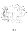
FIG. 1 is a partially exploded perspective view of an embodiment vacuum drive infuser with an embodiment packaging. -
FIG. 2 is a partially exploded perspective view of an embodiment spring-drive infuser with an embodiment packaging. -
FIG. 3 is a partially exploded perspective view of an embodiment coaxial vacuum powered syringe with an embodiment packaging. -
FIG. 4 is a partially exploded perspective view of an embodiment spring-driven infuser, with embodiment packaging. -
FIG. 5 is a partially exploded perspective view of an embodiment gas-driven infuser, with embodiment packaging. -
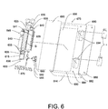
FIG. 6 is a partially exploded perspective view of an embodiment gas-driven infuser, with embodiment packaging. -
FIG. 7 is a partially exploded perspective view of an embodiment elastomeric balloon, with embodiment packaging. -
FIG. 8 is a partially exploded perspective view of an embodiment motor driven infuser with a portion of threaded tube removed to expose worm screw, with embodiment packaging. -
FIG. 9 is a perspective view of an embodiment packaging. - Turning now to
FIG. 1 ,infuser 5 may be comprised of a medication holding vessel, such as asyringe 10 coupled tochamber 15 byclamp 20.Driver 25 is attached to or integrally formed with a portion ofhandle 30 disposed withinchamber 15 and an airtight seal is formed between sliding sealedpiston 35, mounted on the end ofdriver 25, and the inner surface ofchamber 15. Whenhandle 30 is drawn back,piston 35 increases a vacuum force within that portion ofchamber 15 distal topiston 35. In an alternative embodiment,handle 30 is shaped to define aplatform 33 which makes contact with the most proximal surface ofplunger 40. In an alternative embodiment, a portion ofhandle 30 is shaped to formplunger 40 which is in a fluid tight disposition withinsyringe 10.Clamp 20 holdssyringe 10 andchamber 15 tightly together in place to prevent movement ofsyringe 10 relative tochamber 15. - Functionally, the user places medication vial 92 into standard
vial adapter 60, during which sharp center spike 65 penetrates the membrane ofvial 92. A standardmedical stopcock 50 is then oriented to allow the medicament invial 92 to flow intosyringe 10 during standard aspiration ofplunger 40, after first rotatinghandle 30 so thatplatform 33 andplunger 40 are no longer in contact. After the desired amount of medicament has been aspirated intosyringe 10,stopcock 50 is then adjusted to eventually permit the flow of medicament insyringe 10 out of syringe opening 45 and preferably intoinfusion tubing 70. It should be noted thatstopcock 50 may be a two-way, three-way, four-way, or six-way stopcock. - The practitioner then withdraws
infuser handle 30 whereinpiston 35 is drawn back to produce or increase a vacuum inchamber 15. Next,handle 30 may be rotated to allowdriving platform 33 to make contact with and push downwardly onsyringe plunger 40.Handle 30 is then released and the force generated bypiston 35 sliding fowardly to fill the vacuum causesdriver 25 and handle 30 to likewise move forwardly and in so doing, drivesplatform 33 to depressplunger 40. Asplunger 40 moves forwardly withinsyringe 10, a flowable medicament may flow from syringe opening 45 and out ofsyringe 10 into any attachedintravenous tubing 70 or other route of intravenous administration. - In a preferred embodiment,
stopcock 50 and vial adapter 55 may be assistive in controlling flow in and out ofsyringe 10 by permittingsyringe 10 to be filled with medication. For example,stopcock 50, having a first port, second port, and a third port, or more, may be coupled to syringe via luer lock (or other coupling) and opened to provide flow betweensyringe 10 and vial adapter 55. Vial adapter 55 has anouter housing 60 andinner spike 65 capable of piercing the membrane on a standard medication vial. A vial may be inserted along adapter 55 wherein spike 65 pierces the membrane surface of the vial. The user may then actuatestopcock 50 to permit flow fromsyringe 10 throughtubing 70 which is connected by luer lock or other connector. Assyringe 10's plunger 40 moves forwardly medication is forced fromsyringe 10 throughstopcock 50 and throughtubing 70 and thereafter into a patient's circulatory system. - In a preferred embodiment,
infuser 5, or any embodiment infuser described hereinafter, may be disposed within asealable packaging 75.Packaging 75 is comprised of atray 80 which is shaped to define at least one indentation, recess or well to accommodate kit items, andremovable covering 85 that sealstray 80'stop surface 90.Infuser 5 may be disposed withinfirst well 95. One ormore vials 92 may be disposed in one ormore medicament wells 94 which may be identically or differently shaped and correspond to the size and shape of theappropriate vials 92 or other medicament containers to be stored within.Stopcock 50, vial adapter 55 andtubing 70 may be stored in thefirst well 95 or in an alternative embodiment, wells shaped to provide adequate individual storage. In one embodiment, medicaments such asvials 92 are independently sealed byfoldable flap cover 42 which folds alongseam 82 and may be locked into place by a fitable engagement ofprojections 86 and recesses 84.Medication cover 42 may be opened and closed independently ofcover 85, whereincover 85 may remain sealed asmedication cover 42 is opened and closed.Medication cover 42 may be transparent or partially transparent to permit ready medication viewing while medication cover 42 is in the closed position withprojections 86 fitably engaged withinrecesses 84. In this way, written packaging materials and indicia appearing on the surface of vial 92 (or other medicaments disposed within medication recess 94) may be inspected. Information such as medication expiration dates, lot number, and the like may be inspected without opening the packaging. Should it become necessary to change the medicament,medication cover 42 may be opened - removingprojections 86 fromrecesses 84 andmedication cover 42 is folded outwardly and reflected to exposemedication wells 94. After medication has been replaced, cover 42 may be folded inwardly and closed bysnap fitting projections 86 withinrecesses 84. - In an alternative embodiment, the
first well 95 is covered with afirst cover 85, and one ormore medicament wells 94 are covered with a second cover. One or more of the covers covering any wells may be re-sealable. Alternatively, each well may have its own cover which may be re-sealable. - Turning now to
FIG. 2 , an alternative embodiment spring-driveninfuser 200, may be comprised of asyringe 210 coupled tochamber 215 byclamp 220.Handle 30 is shaped to define aplatform 233 which makes contact with the most proximal surface of aplunger 240 found in a typical syringe. In an alternative embodiment, a portion ofhandle 230 is shaped to formplunger 240. Driver 225 is attached to a portion ofhandle 230 disposed withinchamber 215 and terminates inpiston 235.Spring 237 is disposed around driver 225 and has a first end affixed to clamp 220 and second end affixed to the proximal portion ofpiston 235. - In a preferred embodiment,
infuser 200 may be disposed within asealable packaging 275. Packaging 275 is comprised of atray 280 which is shaped to define at least one indentation, recess or well to accommodate kit items, such as well 295, andremovable covering 285seals tray 280'stop surface 290. Cover 242 may be folded alongseam 282 and closed as described above. - Functionally, the user withdraws handle 230 wherein
piston 235 is drawn back to produce compression inspring 237. Compression inspring 237 acting on the proximal side ofpiston 235,biases piston 235, driver 225, and handle 230 forwardly. A portion ofhandle 230 is shaped to formdriver platform 233 which makes contact with and depressplunger 240, which is driven forwardly. In an alternative, a portion ofhandle 230 is shaped to define an integrally formed plunger. Asplunger 240 moves forwardly, a flowable medicament may flow fromsyringe opening 245 and out ofsyringe 210. - Turning now to
FIG. 3 , coaxial vacuum poweredsyringe infuser 300 may be comprised ofchamber 315 segmented intodriver housing 317 andplunger housing 319 by a portion ofchamber 315 shaped to definedivider 323.Shaft 325 is coupled topiston 335 disposed withindriver housing 317 andplunger 340 withinplunger housing 319.Shaft 325 is disposed and moves withinairtight shaft seal 342;shaft seal 342 itself being disposed withinaperture 344 ofdivider 323. The circumferential surface ofpiston 335 andplunger 340 may be rubberized to provide an airtight seal indriver housing 317 and at least a fluidtight seal inplunger housing 319.Chamber 315 is formed with vacuum V existing between the surface ofpiston 335 and the surface ofdivider 323 tending to drivepiston 335 anddivider 323 into contact. It should be noted that in a preferred embodiment,piston 335,shaft 325, andplunger 340 are integrally formed as a single coaxial driver. - Functionally, the user may fill
plunger housing 319 with a flowable medicament. This is accomplished a variety of ways, for example, by attaching a standard syringe to opening 345 and forcing medication out of the standard syringe intoplunger housing 319 or by attaching a syringe tostopcock 350 and actuating it to provide flow betweenstopcock 350 andplunger housing 319. The force of vacuum V is overcome by the force driving medication intoplunger housing 319, andplunger 340,shaft 325, andpiston 335 together move backwardly plungerhousing 315 is filled distally toplunger 340. When vacuum force V is greater than the opposing resistance, medicament may flow fromhousing 319 throughopening 345 andstopcock 350 andtubing 370 when attached. - In a preferred embodiment,
infuser 300 may be disposed within asealable packaging 375. Packaging 375 is comprised of atray 380 which is shaped to define at least one indentation, recess, or well to accommodate kit items, such as well 395, andremovable covering 385seals tray 380'stop surface 390.Infuser 300 and optionally stopcock 350,vial adapter 355 andtubing 370 may be stored in first well 395 or in an alternative embodiment, wells shaped to provide adequate individual storage. - Now,
FIG. 4 demonstratesinfuser 400 which may be comprised of asyringe 410 coupled tochamber 415 byclamp 420.Driver 425 is attached to or integrally formed with a portion ofhandle 430 disposed withinchamber 415.Spring axle 435 is disposed within a relatively distal aspect ofchamber 415 and freely rotatable therein. Flat torsioncoil power spring 438 is affixed toaxle 435 under tension to bias rotation.Wire 441 is affixed toaxle 435 at one end andcoupling 443 at the other end. Coupling 443 is affixed to the terminal aspect ofdriver 425. Whencoil spring 438 rotatesaxle 435,wire 441 is wound ontoaxle 435 andwire 441 applies a traction force to drivedriver 425, handle 430, and handleplatform 433 forwardly withinchamber 415. - Functionally, the user withdraws handle 430 wherein
piston 435 is drawn back to increase tension inspring 438, asdriver 425 andwire 441 affect rotation ofaxle 435.Syringe 410 may be filled with a flowable medicament by the standard means of aspiration. When the desired volume of medicament has been collected withinsyringe 410, handle 430 is energized by pullinghandle 430 back, following which, handle 430 is rotated sufficiently to engagedriver platform 433 andplunger 440. When handle 430 is released, the force generated bydriver 425 moving forwardly drives handle 430,platform 433, and depressesplunger 440 forwardly causing medication to flow from withinsyringe 410 throughopening 445. - Turning now to
FIG. 5 ,infuser 500 may be comprised of asyringe 510 coupled tochamber 515, the chamber having a top and bottom, byclamp 520.Driver 525 is attached to a portion ofhandle 530 and disposed withinchamber 515. Sliding sealedpiston 535 is mounted on the end ofdriver 525, and a seal is formed between sliding sealedpiston 535 and the inner surface ofchamber 515 and cap 537 seals the top ofchamber 515.Driver 525 passes through aperture 539 incap 537 withdriver 525 and cap forming an airtight seal. Gas, such as CO2, nitrogen, or air, pressurizes thechamber 515 such that gas pressure G exerts positive pressure betweencap 537 andpiston 535 to drivedriver 525 forwardly. The terminal aspect ofchamber 515 has opening 536 to provide air to move in and expelled fromchamber 515 distal topiston 535. A portion ofhandle 530 is shaped to defineplatform 533 which makes contact with the most proximal surface of aplunger 540 found in a typical syringe. In the alternative, aportion handle 530 is shaped to define an integrally formed plunger disposed forming a syringe. - Functionally, the user withdraws handle 530 wherein
piston 535 is drawn back to further compress the gas G inchamber 515, raising the pressure and energizing the apparatus. Thesyringe 510 may be filled with a flowable medicament in the usual way frommedicament vial 592, by aspirating the medicament throughstopcock 550 into the syringe when themedicament vial 592 is spiked ontovial adapter 555. Whensyringe 510 has been filled with the desired amount of medication, handle 530 is rotated to placeplatform 533 into alignment withplunger 540 and released. The force generated bypiston 535 sliding forwardly, driven by the force of compressed gas G, causesdriver 525 and handle 530 to likewise move forwardly and in so doing, driveplunger 540 withinsyringe 510. Asplunger 540 moves forwardly, a flowable medicament may flow from syringe opening 545 and out ofsyringe 510. -
FIG. 6 illustratesinfuser 600 which may be comprised of adriver 625 coupled topiston 635 disposed withchamber 615. A seal, such as one or more O-rings 633 are located on the circumferential surface ofpiston 635 to provide a seal.Driver 625 is attached to a portion ofhandle 630 shaped to defineplatform 633 that makes contact with a standard syringe.Driver 625 passes throughaperture 639 sealed with O-ring 641 such seal being airtight. Gas, such as CO2, nitrogen, or air, is stored withincylinder 643 flows throughregulator 646 intopressurize chamber 615; gas pressure G exerts positive pressure to drivedriver 625 forwardly. A portion ofhandle 630 is shaped to define aplatform 633 which makes contact with the most proximal surface of aplunger 640 of a typical syringe. - Functionally, gas G flows from
cylinder 643 throughregulator 646 intochamber 615, raising pressure. When the force of gas pressure G exceeds the force of the piston's static resistance (i.e. between ofpiston 635 and chamber 615) and the forces acting onplatform 633,piston 635 will move forwardly to driveplatform 633 and anystandard syringe plunger 640 in contact therewith.Regulator 646 maintains a constant pressure inchamber 615 so that the pressure force remains the same throughout the infusion cycle. - Turning now to
FIG. 7 ,infuser 700 consists of a single or double walledelastomeric balloon 710 having an internal reservoir 715 capable of holding medication.Balloon 710 terminates in acoupling 720 capable of reversibly attaching tostopcock 750,intravenous tubing 770, or a standard syringe. Filledelastomeric balloon 710 has sufficient resiliency to generate an effective amount of force to drive a medicament throughtubing 770. A medicament may be prepackaged within reservoir 715 or reservoir 715 may be filled by a standard syringe. - In a preferred embodiment,
infuser 700 may be disposed within asealable packaging 775. Packaging 775 is comprised of atray 780 which is shaped to define at least one indentation, recess or well to accommodate kit items, such as well 795, and aremovable covering 785seals tray 780'stop surface 790.Infuser 700 and optionally stopcock 750,vial adapter 755 andtubing 770 may be stored in first well 795 or in an alternative embodiment, disposed within wells shaped to provide adequate individual storage. -
FIG. 8 illustrates anembodiment infuser 800 having an integrated circuit and attachedbattery 802 electrically coupled to reversibleservo gearhead motor 804.Worm screw 820 is coupled tomotor 804 by coupling 805 at screw's first end.FIG. 8 illustrates threadedtube 815 which forms part ofdriver housing arm 830 and threadedtube 815 is disposed withinhousing 816.Worm screw 820 is disposed within threadedtube 815.FIG. 8 illustrates a portion of threadedtube 815, with a portion oftube 815 omitted (for illustrative purposes) to showworm screw 820 disposed therein. The second end ofscrew 820 is disposed withindriver arm 830.Platform 833 may make contact withplunger 840 ofsyringe 810. - Functionally, when circuit is closed,
motor 804 actuates to rotatably driveworm screw 820.Worm screw 820 threadably engages threadedtube 815 resulting inworm screw 820 being driven axially forwardly drivingarm 830 andplatform 833 downwardly to depressplunger 840 and force a flowable medicament fromsyringe 810.Motor 804 may be reversed to drive worm screw axially backwardly. - In a preferred embodiment,
infuser 800 may be disposed within asealable packaging 875. Packaging 875 is comprised of atray 880 which is shaped to define at least one indentation, recess or well to accommodate kit items, such as well 895, and aremovable covering 885seals tray 880'stop surface 790.Infuser 800 and optionally stopcock 850,vial adapter 855 andtubing 870 may be stored in first well 895 or in an alternative embodiment, disposed within wells shaped to provide adequate individual storage. - With regard to the kit covering, in an alternative embodiment, illustrated by
FIG. 9 ,seam 82, recesses 84, andprojections 84 are omitted, and the top surface is uniform. In one embodiment, the top surface may be covered with aremovable covering 925. In one embodiment, covering 925 is a single use cover; in an alternative embodiment,cover 925 is a single reusable cover which may be replaced over the top surface to re-seal all contents within tray 950. It should be realized thattray packaging 900 may be used with medical apparatus and medicaments of all types. - Several example embodiments are described above. The general inventive concepts include use of a force applicator acting on a flowable therapeutic substance or medicament within a vessel. In several of present embodiments described above, the containing vessel is a syringe coupled to several embodiments of a force applicator in a side-by-side or coaxial arrangement. It should be immediately recognized that the location, arrangement, and relative size of the vessel, force applicator, and/or handle may be changed without departing from the spirit and scope of the invention. Further, in several embodiments, an example component of a force applicator includes a handle which forms or engages a portion of a standard syringe.
- As is customary, ultimately, the infusion and patient clinical response is monitored by the professional administering the medicament. In some therapeutic settings, the apparatus may be utilized with limited clinician involvement (e.g. infusion of antibiotics). In other settings, the apparatus is utilized with active bedside clinician involvement (e.g. anesthetics or potent analgesics) where patient response is actively monitored, and the infusion may be interrupted when a desirable clinical effect is achieved. As is also customary, the infusion may be interrupted where an undesirable or adverse clinical effect is encountered. It should be recognized that a force applicator may take a variety of shapes and sizes to impart force on a flowable therapeutic substance without departing from the scope and spirit of the present invention.
- The term medicament, as used herein, refers to any flowable substance which may have therapeutic benefit. Further, the apparatus described herein may be utilized without regard to intravenous line placement, and may be utilized to provide an infusion through central and peripheral venous access locations. It should be recognized that the system described herein may be utilized to provide infusion through any therapeutically acceptable location, including but not limited to intraosseous, epidural, intrathecal, or intraperitoneal routes.
- It should be further recognized, that the present invention may be utilized to facilitate mixture, admixture, or reconstitution of medication, and the embodiment vial housing can be used to facilitate reconstitution of powered medicaments. For example, a dilutent vial may be puncturingly engaged on an embodiment vial adapter and stopcock engaged to permit flow between a syringe and vial and permit dilutent aspiration into the syringe. The stopcock may be aligned to close flow between the syringe and vial, and a second vial containing the medicament to be reconstituted puncturingly engaged on the vial adapter whereupon, stopcock may be aligned to permit flow between the syringe and vial to allow dilutent to be instilled into vial where it can be agitated and mixed according to manufacturer's instructions and accepted clinical practices. Further, the number, size, shape, and contents of medication vials may be variable. For example, several vials containing the same substance may be provided where repeat dosing is foreseeable.
- Further, the present invention describes, in part, a kit containing medical apparatus to facilitate the infusion of therapeutic substances and medications or adjunctive solutions contained within that kit where the apparatus and medications are separately contained and where the medications may be inspected and accessed without opening that portion of the kit containing apparatus. It should be immediately recognized that the inventive kit herein described may be utilized with any type of medical apparatus capable of being separately sealed.
- The syringe and/or force applicator may or may not be have indicia printed or etched thereupon. Examples of such indicia include such information to facilitate accurate medication administration such as cubic centimeters (cc), milliliters (ml), age, weight, and dosing information.
- The present invention may be practiced with several medication classes, including, but not limited to: opiates, opioids, sedatives, benzodiazepines, propofol, vasopressors, anesthetics, vasodialators, anticoagulants, antibiotics, antiarrhythmics, antiepileptics, antirheumatic drugs, steroids, chemotherapeutic agents, and progestins. It should be noted that the term medicament, as used herein, refers to any substance which may have a potential health benefit or therapeutic use.
- References are made herein to the spatial orientation of the inventive apparatus. Distal and distally are used to refer to points relatively closer to the subject patient (e.g. furthest from handle 225); whereas proximal and proximally referring to points relatively further from the patient (e.g. closest to handle 225). Forwardly and backwardly are used to describe the movement of certain embodiments and forward and forwardly refer to movement in the direction of opening 230 whereas backward or backwardly refer to movement away from opening 230. The inventive infuser embodiments described herein may be practiced with or without the use of the example packaging, and the apparatus described herein may be packaged according to any acceptable custom. Stopcocks, vials, and tubing are described as optional embodiments and may or may not be included used with the inventive infuser/medicament containing vessel.
Claims (11)
- An infusion kit comprising:an infuser (5); a medicament containing vessel having an opening capable of receiving andholding a flowable medicament therein, said vessel operatively coupled to said infuser, wherein said infuser is capable of exerting sufficient pressure within said vessel to cause the medicament to flow from said vessel's opening; a tray (80) having a top surface (90) and shaped to define a first well (95) and at least one medicament well (94); at least one cover (85) sealed over said first well (95) of said tray's top surface (90); said first well having said infuser and said vessel therein, beneath said cover; a medication vial (92) located in said at least one medicament well (94); said medication vial independently sealed in said medicament well relative to said cover (85) by a medication cover (42); characterised in that said cover (85) over said first well remains sealed as said medication cover (42) is opened and closed.
- The infusion kit of claim 1, wherein said medication cover (42) includes a foldable flap cover (42), which folds along a seam (82).
- The infusion kit of claim 2, wherein said foldable flap cover (42) is removably locked in place by a fixable engagement of projections (86) and recesses (84) in the foldable flap cover and top surface of said tray.
- The infusion kit of any preceding claim, wherein said medication cover (42) is at least partially transparent to permit reading of information on said medication vial (92) through said medication cover.
- The infusion kit of claim 1, wherein said infuser further comprises: a chamber (15), a driver (25) disposed with said chamber, a piston (35) mounted on the end of said driver, wherein an airtight seal is formed between said piston and said chamber, a handle (30) integrally formed with said driver, wherein when handle is drawn back, a vacuum force is created within said chamber distal to said piston; a clamp (20) coupled to said chamber; wherein said medicament containing vessel is comprised of a syringe (10) coupled to said chamber by said clamp, wherein syringe and chamber are held tightly together.
- The infusion kit of claim 1, wherein said infuser further comprises: a chamber (15), a driver (25) disposed within said chamber, a piston (35), having a proximal portion and distal portion, said piston mounted on the end of said driver, a spring (237) having a first end and second end, said spring disposed around the driver, a clamp (20) coupled to said chamber, wherein said medicament containing vessel is comprised of a syringe (10) coupled to said chamber by said clamp, wherein syringe and clamp are held tightly together, a handle (30) integrally formed with said driver, wherein the first end of said spring is affixed to the clamp, wherein the second end of said spring is affixed to the proximal portion of the piston, a handle attached to said driver, wherein when handle is drawn back, a spring force is created within said chamber to bias said piston, driver, and handle forwardly.
- The infusion kit of claim 1, wherein said infuser further comprises: a chamber (15), a driver (25) disposed within said chamber, wherein said medicament containing vessel is comprised of a syringe (10) coupled to said chamber by a clamp (20), wherein syringe and clamp are held tightly together, a handle (30) integrally formed with said driver, wherein a freely rotatable spring axle (435) is disposed within a relatively distal aspect of said chamber, wherein a flat torsion coil power spring is affixed to said axle to bias rotation, wherein a wire (441) with a first and second end, the first end is affixed to said axle, wherein a coupling is affixed to the terminal aspect of said driver (25), wherein the second end of wire is affixed to said coupling, wherein said spring rotates axle to wind the wire around said axle, wherein said wire applies a traction force to drive driver (25) and handle (30) forwardly.
- The infusion kit of claim 1, wherein said infuser further comprises: a chamber (15), a driver (25) disposed within said chamber having a top and bottom, wherein said medicament containing vessel is comprised of a syringe (10) coupled to said chamber by a clamp (20), wherein syringe and clamp are held tightly together, a handle (30) integrally formed with said driver, a cap (537) having an aperture said driver passing through said aperture, said driver and cap forming an airtight seal on the chamber's top, a sliding sealed piston (535) mounted on the end of said driver, the piston disposed within said chamber, a compressed gas pressurizing said chamber between said cap and said piston, wherein said piston, driver, and handle are driven forwardly.
- The infusion kit of claim 8, wherein said infuser further comprises, a regulator (646) operatively coupled to said chamber (15), a gas cylinder operatively coupled to said regulator, wherein the regulator maintains a constant pressure in said chamber, wherein the pressure force stays constant throughout the infusion cycle.
- The infusion kit of any preceding claim, further comprising a stopcock (50) capable of being coupled to said medicament containing vessel; a vial adapter (55) capable of being coupled to said stopcock; intravenous tubing (70) capable of being coupled to said stopcock or medicament containing vessel.
- The infusion kit of claim 1, further comprising: a three-way stopcock (50) having a first port, a second port, and a third port, the first port of said stopcock operatively coupled to said vessel's opening, said stopcock disposed within said first well (95); a vial adapter (55) operatively coupled to said second port of said stopcock, said vial adaptor disposed within first well; an infusion tubing (70) operatively coupled to the third port of said stopcock, said infusion tubing disposed within said first well; wherein the stopcock may be rotated to obstruct a single port and permit flowable materials to flow between the remaining two ports.
Applications Claiming Priority (2)
| Application Number | Priority Date | Filing Date | Title |
|---|---|---|---|
| US39764210P | 2010-06-14 | 2010-06-14 | |
| PCT/US2011/040376 WO2011159714A2 (en) | 2010-06-14 | 2011-06-14 | Medication infusion kit |
Publications (3)
| Publication Number | Publication Date |
|---|---|
| EP2579918A2 EP2579918A2 (en) | 2013-04-17 |
| EP2579918A4 EP2579918A4 (en) | 2013-11-20 |
| EP2579918B1 true EP2579918B1 (en) | 2015-08-12 |
Family
ID=45096799
Family Applications (1)
| Application Number | Title | Priority Date | Filing Date |
|---|---|---|---|
| EP11796312.4A Not-in-force EP2579918B1 (en) | 2010-06-14 | 2011-06-14 | Medication infusion kit |
Country Status (5)
| Country | Link |
|---|---|
| US (3) | US8517989B2 (en) |
| EP (1) | EP2579918B1 (en) |
| AU (1) | AU2011267879A1 (en) |
| CA (1) | CA2801200C (en) |
| WO (1) | WO2011159714A2 (en) |
Families Citing this family (15)
| Publication number | Priority date | Publication date | Assignee | Title |
|---|---|---|---|---|
| CA2801200C (en) * | 2010-06-14 | 2019-02-26 | David R. Duncan | Medication infusion kit |
| WO2013070259A1 (en) * | 2011-11-08 | 2013-05-16 | Duncan David R | Compact non-electric medicament infuser |
| WO2013120182A1 (en) * | 2012-02-17 | 2013-08-22 | Bernard Fresco | First-aid kit with backing member |
| KR102065804B1 (en) * | 2012-07-03 | 2020-01-13 | 바이오버라티브 테라퓨틱스 인크. | Device container |
| WO2014046950A1 (en) | 2012-09-24 | 2014-03-27 | Enable Injections, Llc | Medication vial and injector assemblies and methods of use |
| WO2014204894A2 (en) | 2013-06-18 | 2014-12-24 | Enable Injections, Llc | Vial transfer and injection apparatus and method |
| US20150044633A1 (en) * | 2013-08-06 | 2015-02-12 | Stoma Ventures, LLC | Water kit assembly |
| US10872313B2 (en) | 2015-06-02 | 2020-12-22 | ROCA Medical Ltd. | Method for repurposing NDC codes in a pharmaceutical database for venom derived allergens involved in venom immunotherapy |
| WO2016041868A1 (en) * | 2014-09-15 | 2016-03-24 | Sanofi | Packaging for medical device and medicament |
| ES2669744T3 (en) * | 2015-05-25 | 2018-05-29 | Chiapatti, Andrea | Fluid flow switching device for catheterization with a three-way bladder catheter |
| US10369215B2 (en) | 2015-06-02 | 2019-08-06 | ROCA Medical Ltd. | Predilution sets for distributing antigens |
| US10548974B2 (en) | 2015-06-02 | 2020-02-04 | ROCA Medical Ltd. | Therapeutic treatment kit for allergies based on DNA profiles |
| WO2020167702A1 (en) * | 2019-02-12 | 2020-08-20 | Amgen Inc. | Take-home drug delivery system |
| CN110811906B (en) * | 2019-11-21 | 2021-10-15 | 江苏农牧科技职业学院 | Medical advanced immunization device for pseudorabies of piglets in positive pig farm |
| US20210282517A1 (en) * | 2020-03-12 | 2021-09-16 | Gary Trenda | Germ Fighting Reserve System |
Citations (1)
| Publication number | Priority date | Publication date | Assignee | Title |
|---|---|---|---|---|
| WO2003064282A2 (en) * | 2002-01-30 | 2003-08-07 | Mars Incorporated | Multiple pack and method of producing same |
Family Cites Families (41)
| Publication number | Priority date | Publication date | Assignee | Title |
|---|---|---|---|---|
| US3329261A (en) * | 1965-09-03 | 1967-07-04 | Bard Inc C R | Catheterization package |
| GB1455126A (en) * | 1973-03-09 | 1976-11-10 | Lunch Locker Systems Ltd | Packaging containers |
| US3851649A (en) * | 1973-03-21 | 1974-12-03 | Kendall & Co | Catheterization package |
| US4128173A (en) * | 1975-10-28 | 1978-12-05 | Harrison Lazarus | Peritoneal fluid treatment apparatus, package and method |
| GB1549402A (en) | 1976-09-28 | 1979-08-08 | Pye Ltd | Apparatus for delivering fluids with controlled rate of flow |
| USD282280S (en) * | 1983-01-26 | 1986-01-21 | Johnson & Johnson Dental Products Company | Hinged container with component inserts |
| US4523679A (en) * | 1984-03-05 | 1985-06-18 | Sterling Drug Inc. | Pre-sterilized medical procedure kit packages |
| US4595102A (en) * | 1984-12-18 | 1986-06-17 | The Kendall Company | Kit for performing a medical procedure |
| US4658957A (en) | 1985-01-28 | 1987-04-21 | Abbott Laboratories | Utility tray |
| US4722733A (en) * | 1986-02-26 | 1988-02-02 | Intelligent Medicine, Inc. | Drug handling apparatus and method |
| US4966585A (en) | 1988-05-31 | 1990-10-30 | Gangemi Ronald J | Infusion apparatus |
| US5059182A (en) | 1989-04-12 | 1991-10-22 | David H. Laing | Portable infusion device |
| US5135500A (en) | 1989-10-31 | 1992-08-04 | Prime Medical Products, Inc. | Self-driven pump device |
| US5024664A (en) | 1990-04-26 | 1991-06-18 | Baxter International Inc. | Vacuum infusion device |
| US5290259A (en) | 1993-02-18 | 1994-03-01 | Ultradent Products, Inc. | Double syringe delivery system |
| JPH07227424A (en) * | 1994-02-17 | 1995-08-29 | Japan Storage Battery Co Ltd | Fluid transporting device |
| DE69518213D1 (en) * | 1994-04-27 | 2000-09-07 | Daiken Iki Co Ltd | DEVICE FOR INJECTING LIQUIDS |
| US5505709A (en) | 1994-09-15 | 1996-04-09 | Minimed, Inc., A Delaware Corporation | Mated infusion pump and syringe |
| US5810202A (en) | 1994-10-20 | 1998-09-22 | Rick R. Wascher, P.C. | Disposable self-dispensing pressurized package for delivery of sterile fluids and solutions |
| FR2758088B1 (en) | 1997-01-06 | 1999-04-16 | Medex Sa | MEDICAL LIQUID INJECTION DEVICE |
| US6012586A (en) * | 1997-11-24 | 2000-01-11 | Maxxim Medical, Inc. | Medical procedure kit |
| DE19809483A1 (en) * | 1998-03-06 | 1999-09-30 | Daum Gmbh | Injecting apparatus for injecting fluid into the human body |
| JP3416943B2 (en) | 1998-03-27 | 2003-06-16 | ニプロ株式会社 | Chemical solution injection device using negative pressure |
| US6283943B1 (en) | 1999-02-19 | 2001-09-04 | Minimed Inc. | Negative pressure pump |
| JP2001333980A (en) | 2000-05-26 | 2001-12-04 | Ookisu:Kk | Continuous liquid medicine injector |
| EP1379191B1 (en) * | 2001-04-13 | 2005-11-09 | I-Flow Corporation | Sterile container for medical applications |
| US7037289B2 (en) * | 2001-09-12 | 2006-05-02 | 3M Innovative Properties Company | Apparatus and methods for dispensing an adhesive tissue sealant |
| US6896141B2 (en) * | 2002-02-28 | 2005-05-24 | Kimberly-Clark Worldwide, Inc. | Surgical kit with multiple planar recess surfaces |
| US6910581B2 (en) * | 2002-02-28 | 2005-06-28 | Kimberly-Clark Worldwide, Inc. | Surgical kit for “pull” type percutaneous endoscopic gastrostomy procedures |
| US7270648B2 (en) * | 2002-12-23 | 2007-09-18 | Farhad Kazemzadeh | Drug delivery apparatus |
| US20050098470A1 (en) | 2003-11-12 | 2005-05-12 | Davis Michael J. | Kit for administration of a drug |
| JP3635647B1 (en) * | 2004-03-29 | 2005-04-06 | 株式会社アグリス | Medical kit |
| US7731678B2 (en) * | 2004-10-13 | 2010-06-08 | Hyprotek, Inc. | Syringe devices and methods for mixing and administering medication |
| US7806265B2 (en) * | 2006-07-12 | 2010-10-05 | Mobius Therapeutics, Llc | Apparatus and method for reconstituting a pharmaceutical and preparing the reconstituted pharmaceutical for transient application |
| US20090149527A1 (en) * | 2006-11-03 | 2009-06-11 | Mobius Therapeutics, Llc | Apparatus and Method for Application of a Pharmaceutical to a Surface of an External Ear Canal for Treatment of Keratosis Obutrans |
| US20080237083A1 (en) * | 2007-03-27 | 2008-10-02 | Mahaffy Hugh W | Systems and methods for providing and using medical items |
| US7976505B2 (en) | 2007-12-19 | 2011-07-12 | Calibra Medical, Inc. | Disposable infusion device negative pressure filling apparatus and method |
| US20090198217A1 (en) * | 2008-02-06 | 2009-08-06 | Gale H. Thome, JR. | Convenience IV kits and methods of use |
| US20100274205A1 (en) * | 2009-04-24 | 2010-10-28 | Morelli Rocco R | Wound care kit |
| US9399095B2 (en) | 2009-05-27 | 2016-07-26 | David R. Duncan | Compact non-electric medicament infuser |
| CA2801200C (en) * | 2010-06-14 | 2019-02-26 | David R. Duncan | Medication infusion kit |
-
2011
- 2011-06-14 CA CA2801200A patent/CA2801200C/en active Active
- 2011-06-14 WO PCT/US2011/040376 patent/WO2011159714A2/en active Application Filing
- 2011-06-14 US US13/160,279 patent/US8517989B2/en active Active
- 2011-06-14 EP EP11796312.4A patent/EP2579918B1/en not_active Not-in-force
- 2011-06-14 AU AU2011267879A patent/AU2011267879A1/en not_active Abandoned
-
2013
- 2013-07-29 US US13/953,725 patent/US20130313156A1/en not_active Abandoned
-
2016
- 2016-04-13 US US15/097,965 patent/US20160221709A1/en not_active Abandoned
Patent Citations (1)
| Publication number | Priority date | Publication date | Assignee | Title |
|---|---|---|---|---|
| WO2003064282A2 (en) * | 2002-01-30 | 2003-08-07 | Mars Incorporated | Multiple pack and method of producing same |
Also Published As
| Publication number | Publication date |
|---|---|
| EP2579918A2 (en) | 2013-04-17 |
| WO2011159714A2 (en) | 2011-12-22 |
| WO2011159714A3 (en) | 2012-04-12 |
| EP2579918A4 (en) | 2013-11-20 |
| AU2011267879A1 (en) | 2012-12-06 |
| US20160221709A1 (en) | 2016-08-04 |
| CA2801200C (en) | 2019-02-26 |
| US20110306928A1 (en) | 2011-12-15 |
| CA2801200A1 (en) | 2011-12-22 |
| US20130313156A1 (en) | 2013-11-28 |
| US8517989B2 (en) | 2013-08-27 |
Similar Documents
| Publication | Publication Date | Title |
|---|---|---|
| EP2579918B1 (en) | Medication infusion kit | |
| US11458256B2 (en) | Apparatus and kits for fluid infusion | |
| US10322227B2 (en) | Apparatus, kits and related methods for fluid infusion | |
| US20200405951A1 (en) | Injection or infusion device comprising an improved housing and release liner for removing sterile barrier films using the release liner | |
| US5480386A (en) | Pump assembly for medical use | |
| JP4509100B2 (en) | Infusion device attachable to skin with removable needle insertion actuation | |
| US10688294B2 (en) | Portable fluid delivery system | |
| US20130274656A1 (en) | Device for mixing at least two constituents | |
| JPH07501234A (en) | Pharmaceutical injector and method | |
| BRPI1015947B1 (en) | drug delivery devices and related systems and methods | |
| WO1993002921A1 (en) | Metered syringe filling device for pharmaceutical containers | |
| EP3212253B1 (en) | Time controlled periodic infusion | |
| US5707365A (en) | Insulin dispenser | |
| EP4154926A1 (en) | An improved needle insertion mechanism for an injection or infusion device | |
| US11957886B2 (en) | Rapid fluid delivery system | |
| CN219579582U (en) | System for infusing and delivering a drug |
Legal Events
| Date | Code | Title | Description |
|---|---|---|---|
| PUAI | Public reference made under article 153(3) epc to a published international application that has entered the european phase |
Free format text: ORIGINAL CODE: 0009012 |
|
| 17P | Request for examination filed |
Effective date: 20130114 |
|
| AK | Designated contracting states |
Kind code of ref document: A2 Designated state(s): AL AT BE BG CH CY CZ DE DK EE ES FI FR GB GR HR HU IE IS IT LI LT LU LV MC MK MT NL NO PL PT RO RS SE SI SK SM TR |
|
| DAX | Request for extension of the european patent (deleted) | ||
| A4 | Supplementary search report drawn up and despatched |
Effective date: 20131018 |
|
| RIC1 | Information provided on ipc code assigned before grant |
Ipc: A61M 5/14 20060101AFI20131014BHEP Ipc: B65D 5/50 20060101ALI20131014BHEP Ipc: A61M 5/145 20060101ALI20131014BHEP Ipc: A61M 39/08 20060101ALI20131014BHEP Ipc: A61M 5/152 20060101ALI20131014BHEP Ipc: A61M 39/22 20060101ALI20131014BHEP Ipc: A61J 1/20 20060101ALI20131014BHEP |
|
| 17Q | First examination report despatched |
Effective date: 20140625 |
|
| REG | Reference to a national code |
Ref country code: DE Ref legal event code: R079 Ref document number: 602011018779 Country of ref document: DE Free format text: PREVIOUS MAIN CLASS: A61M0005140000 Ipc: A61M0005000000 |
|
| GRAP | Despatch of communication of intention to grant a patent |
Free format text: ORIGINAL CODE: EPIDOSNIGR1 |
|
| RIC1 | Information provided on ipc code assigned before grant |
Ipc: A61M 5/00 20060101AFI20150213BHEP Ipc: A61M 5/168 20060101ALI20150213BHEP Ipc: B65D 77/20 20060101ALI20150213BHEP |
|
| INTG | Intention to grant announced |
Effective date: 20150310 |
|
| GRAS | Grant fee paid |
Free format text: ORIGINAL CODE: EPIDOSNIGR3 |
|
| GRAA | (expected) grant |
Free format text: ORIGINAL CODE: 0009210 |
|
| AK | Designated contracting states |
Kind code of ref document: B1 Designated state(s): AL AT BE BG CH CY CZ DE DK EE ES FI FR GB GR HR HU IE IS IT LI LT LU LV MC MK MT NL NO PL PT RO RS SE SI SK SM TR |
|
| REG | Reference to a national code |
Ref country code: GB Ref legal event code: FG4D |
|
| REG | Reference to a national code |
Ref country code: CH Ref legal event code: EP |
|
| REG | Reference to a national code |
Ref country code: AT Ref legal event code: REF Ref document number: 741558 Country of ref document: AT Kind code of ref document: T Effective date: 20150815 |
|
| REG | Reference to a national code |
Ref country code: IE Ref legal event code: FG4D |
|
| REG | Reference to a national code |
Ref country code: DE Ref legal event code: R096 Ref document number: 602011018779 Country of ref document: DE |
|
| REG | Reference to a national code |
Ref country code: LT Ref legal event code: MG4D |
|
| REG | Reference to a national code |
Ref country code: AT Ref legal event code: MK05 Ref document number: 741558 Country of ref document: AT Kind code of ref document: T Effective date: 20150812 |
|
| REG | Reference to a national code |
Ref country code: NL Ref legal event code: MP Effective date: 20150812 |
|
| PG25 | Lapsed in a contracting state [announced via postgrant information from national office to epo] |
Ref country code: NO Free format text: LAPSE BECAUSE OF FAILURE TO SUBMIT A TRANSLATION OF THE DESCRIPTION OR TO PAY THE FEE WITHIN THE PRESCRIBED TIME-LIMIT Effective date: 20151112 Ref country code: FI Free format text: LAPSE BECAUSE OF FAILURE TO SUBMIT A TRANSLATION OF THE DESCRIPTION OR TO PAY THE FEE WITHIN THE PRESCRIBED TIME-LIMIT Effective date: 20150812 Ref country code: LV Free format text: LAPSE BECAUSE OF FAILURE TO SUBMIT A TRANSLATION OF THE DESCRIPTION OR TO PAY THE FEE WITHIN THE PRESCRIBED TIME-LIMIT Effective date: 20150812 Ref country code: LT Free format text: LAPSE BECAUSE OF FAILURE TO SUBMIT A TRANSLATION OF THE DESCRIPTION OR TO PAY THE FEE WITHIN THE PRESCRIBED TIME-LIMIT Effective date: 20150812 Ref country code: GR Free format text: LAPSE BECAUSE OF FAILURE TO SUBMIT A TRANSLATION OF THE DESCRIPTION OR TO PAY THE FEE WITHIN THE PRESCRIBED TIME-LIMIT Effective date: 20151113 |
|
| PG25 | Lapsed in a contracting state [announced via postgrant information from national office to epo] |
Ref country code: SE Free format text: LAPSE BECAUSE OF FAILURE TO SUBMIT A TRANSLATION OF THE DESCRIPTION OR TO PAY THE FEE WITHIN THE PRESCRIBED TIME-LIMIT Effective date: 20150812 Ref country code: IS Free format text: LAPSE BECAUSE OF FAILURE TO SUBMIT A TRANSLATION OF THE DESCRIPTION OR TO PAY THE FEE WITHIN THE PRESCRIBED TIME-LIMIT Effective date: 20151212 Ref country code: PT Free format text: LAPSE BECAUSE OF FAILURE TO SUBMIT A TRANSLATION OF THE DESCRIPTION OR TO PAY THE FEE WITHIN THE PRESCRIBED TIME-LIMIT Effective date: 20151214 Ref country code: RS Free format text: LAPSE BECAUSE OF FAILURE TO SUBMIT A TRANSLATION OF THE DESCRIPTION OR TO PAY THE FEE WITHIN THE PRESCRIBED TIME-LIMIT Effective date: 20150812 Ref country code: AT Free format text: LAPSE BECAUSE OF FAILURE TO SUBMIT A TRANSLATION OF THE DESCRIPTION OR TO PAY THE FEE WITHIN THE PRESCRIBED TIME-LIMIT Effective date: 20150812 Ref country code: PL Free format text: LAPSE BECAUSE OF FAILURE TO SUBMIT A TRANSLATION OF THE DESCRIPTION OR TO PAY THE FEE WITHIN THE PRESCRIBED TIME-LIMIT Effective date: 20150812 Ref country code: HR Free format text: LAPSE BECAUSE OF FAILURE TO SUBMIT A TRANSLATION OF THE DESCRIPTION OR TO PAY THE FEE WITHIN THE PRESCRIBED TIME-LIMIT Effective date: 20150812 Ref country code: ES Free format text: LAPSE BECAUSE OF FAILURE TO SUBMIT A TRANSLATION OF THE DESCRIPTION OR TO PAY THE FEE WITHIN THE PRESCRIBED TIME-LIMIT Effective date: 20150812 |
|
| PG25 | Lapsed in a contracting state [announced via postgrant information from national office to epo] |
Ref country code: NL Free format text: LAPSE BECAUSE OF FAILURE TO SUBMIT A TRANSLATION OF THE DESCRIPTION OR TO PAY THE FEE WITHIN THE PRESCRIBED TIME-LIMIT Effective date: 20150812 |
|
| PG25 | Lapsed in a contracting state [announced via postgrant information from national office to epo] |
Ref country code: IT Free format text: LAPSE BECAUSE OF FAILURE TO SUBMIT A TRANSLATION OF THE DESCRIPTION OR TO PAY THE FEE WITHIN THE PRESCRIBED TIME-LIMIT Effective date: 20150812 Ref country code: DK Free format text: LAPSE BECAUSE OF FAILURE TO SUBMIT A TRANSLATION OF THE DESCRIPTION OR TO PAY THE FEE WITHIN THE PRESCRIBED TIME-LIMIT Effective date: 20150812 Ref country code: CZ Free format text: LAPSE BECAUSE OF FAILURE TO SUBMIT A TRANSLATION OF THE DESCRIPTION OR TO PAY THE FEE WITHIN THE PRESCRIBED TIME-LIMIT Effective date: 20150812 Ref country code: SK Free format text: LAPSE BECAUSE OF FAILURE TO SUBMIT A TRANSLATION OF THE DESCRIPTION OR TO PAY THE FEE WITHIN THE PRESCRIBED TIME-LIMIT Effective date: 20150812 Ref country code: EE Free format text: LAPSE BECAUSE OF FAILURE TO SUBMIT A TRANSLATION OF THE DESCRIPTION OR TO PAY THE FEE WITHIN THE PRESCRIBED TIME-LIMIT Effective date: 20150812 |
|
| REG | Reference to a national code |
Ref country code: DE Ref legal event code: R097 Ref document number: 602011018779 Country of ref document: DE |
|
| PG25 | Lapsed in a contracting state [announced via postgrant information from national office to epo] |
Ref country code: RO Free format text: LAPSE BECAUSE OF FAILURE TO SUBMIT A TRANSLATION OF THE DESCRIPTION OR TO PAY THE FEE WITHIN THE PRESCRIBED TIME-LIMIT Effective date: 20150812 |
|
| PLBE | No opposition filed within time limit |
Free format text: ORIGINAL CODE: 0009261 |
|
| STAA | Information on the status of an ep patent application or granted ep patent |
Free format text: STATUS: NO OPPOSITION FILED WITHIN TIME LIMIT |
|
| REG | Reference to a national code |
Ref country code: FR Ref legal event code: PLFP Year of fee payment: 6 |
|
| 26N | No opposition filed |
Effective date: 20160513 |
|
| PG25 | Lapsed in a contracting state [announced via postgrant information from national office to epo] |
Ref country code: SI Free format text: LAPSE BECAUSE OF FAILURE TO SUBMIT A TRANSLATION OF THE DESCRIPTION OR TO PAY THE FEE WITHIN THE PRESCRIBED TIME-LIMIT Effective date: 20150812 |
|
| PG25 | Lapsed in a contracting state [announced via postgrant information from national office to epo] |
Ref country code: BE Free format text: LAPSE BECAUSE OF FAILURE TO SUBMIT A TRANSLATION OF THE DESCRIPTION OR TO PAY THE FEE WITHIN THE PRESCRIBED TIME-LIMIT Effective date: 20150812 |
|
| PG25 | Lapsed in a contracting state [announced via postgrant information from national office to epo] |
Ref country code: MC Free format text: LAPSE BECAUSE OF FAILURE TO SUBMIT A TRANSLATION OF THE DESCRIPTION OR TO PAY THE FEE WITHIN THE PRESCRIBED TIME-LIMIT Effective date: 20150812 |
|
| REG | Reference to a national code |
Ref country code: CH Ref legal event code: PL |
|
| PG25 | Lapsed in a contracting state [announced via postgrant information from national office to epo] |
Ref country code: LI Free format text: LAPSE BECAUSE OF NON-PAYMENT OF DUE FEES Effective date: 20160630 Ref country code: CH Free format text: LAPSE BECAUSE OF NON-PAYMENT OF DUE FEES Effective date: 20160630 |
|
| REG | Reference to a national code |
Ref country code: FR Ref legal event code: PLFP Year of fee payment: 7 |
|
| PG25 | Lapsed in a contracting state [announced via postgrant information from national office to epo] |
Ref country code: CY Free format text: LAPSE BECAUSE OF FAILURE TO SUBMIT A TRANSLATION OF THE DESCRIPTION OR TO PAY THE FEE WITHIN THE PRESCRIBED TIME-LIMIT Effective date: 20150812 Ref country code: HU Free format text: LAPSE BECAUSE OF FAILURE TO SUBMIT A TRANSLATION OF THE DESCRIPTION OR TO PAY THE FEE WITHIN THE PRESCRIBED TIME-LIMIT; INVALID AB INITIO Effective date: 20110614 Ref country code: SM Free format text: LAPSE BECAUSE OF FAILURE TO SUBMIT A TRANSLATION OF THE DESCRIPTION OR TO PAY THE FEE WITHIN THE PRESCRIBED TIME-LIMIT Effective date: 20150812 |
|
| REG | Reference to a national code |
Ref country code: FR Ref legal event code: PLFP Year of fee payment: 8 |
|
| PG25 | Lapsed in a contracting state [announced via postgrant information from national office to epo] |
Ref country code: TR Free format text: LAPSE BECAUSE OF FAILURE TO SUBMIT A TRANSLATION OF THE DESCRIPTION OR TO PAY THE FEE WITHIN THE PRESCRIBED TIME-LIMIT Effective date: 20150812 Ref country code: MK Free format text: LAPSE BECAUSE OF FAILURE TO SUBMIT A TRANSLATION OF THE DESCRIPTION OR TO PAY THE FEE WITHIN THE PRESCRIBED TIME-LIMIT Effective date: 20150812 Ref country code: LU Free format text: LAPSE BECAUSE OF NON-PAYMENT OF DUE FEES Effective date: 20160614 Ref country code: MT Free format text: LAPSE BECAUSE OF NON-PAYMENT OF DUE FEES Effective date: 20160630 |
|
| PG25 | Lapsed in a contracting state [announced via postgrant information from national office to epo] |
Ref country code: BG Free format text: LAPSE BECAUSE OF FAILURE TO SUBMIT A TRANSLATION OF THE DESCRIPTION OR TO PAY THE FEE WITHIN THE PRESCRIBED TIME-LIMIT Effective date: 20150812 |
|
| PG25 | Lapsed in a contracting state [announced via postgrant information from national office to epo] |
Ref country code: AL Free format text: LAPSE BECAUSE OF FAILURE TO SUBMIT A TRANSLATION OF THE DESCRIPTION OR TO PAY THE FEE WITHIN THE PRESCRIBED TIME-LIMIT Effective date: 20150812 |
|
| PGFP | Annual fee paid to national office [announced via postgrant information from national office to epo] |
Ref country code: IE Payment date: 20190611 Year of fee payment: 9 |
|
| PGFP | Annual fee paid to national office [announced via postgrant information from national office to epo] |
Ref country code: FR Payment date: 20190626 Year of fee payment: 9 |
|
| PGFP | Annual fee paid to national office [announced via postgrant information from national office to epo] |
Ref country code: DE Payment date: 20190624 Year of fee payment: 9 Ref country code: GB Payment date: 20190605 Year of fee payment: 9 |
|
| REG | Reference to a national code |
Ref country code: DE Ref legal event code: R119 Ref document number: 602011018779 Country of ref document: DE |
|
| GBPC | Gb: european patent ceased through non-payment of renewal fee |
Effective date: 20200614 |
|
| PG25 | Lapsed in a contracting state [announced via postgrant information from national office to epo] |
Ref country code: IE Free format text: LAPSE BECAUSE OF NON-PAYMENT OF DUE FEES Effective date: 20200614 Ref country code: GB Free format text: LAPSE BECAUSE OF NON-PAYMENT OF DUE FEES Effective date: 20200614 Ref country code: FR Free format text: LAPSE BECAUSE OF NON-PAYMENT OF DUE FEES Effective date: 20200630 |
|
| PG25 | Lapsed in a contracting state [announced via postgrant information from national office to epo] |
Ref country code: DE Free format text: LAPSE BECAUSE OF NON-PAYMENT OF DUE FEES Effective date: 20210101 |