EP2579639A1 - Quality of Service verification and throughput measurement for minimisation of drive test - Google Patents
Quality of Service verification and throughput measurement for minimisation of drive test Download PDFInfo
- Publication number
- EP2579639A1 EP2579639A1 EP12006881.2A EP12006881A EP2579639A1 EP 2579639 A1 EP2579639 A1 EP 2579639A1 EP 12006881 A EP12006881 A EP 12006881A EP 2579639 A1 EP2579639 A1 EP 2579639A1
- Authority
- EP
- European Patent Office
- Prior art keywords
- measurement
- data
- base station
- data burst
- time
- Prior art date
- Legal status (The legal status is an assumption and is not a legal conclusion. Google has not performed a legal analysis and makes no representation as to the accuracy of the status listed.)
- Withdrawn
Links
- 238000005259 measurement Methods 0.000 title claims abstract description 229
- 238000012360 testing method Methods 0.000 title claims abstract description 17
- 238000012795 verification Methods 0.000 title description 3
- 230000005540 biological transmission Effects 0.000 claims abstract description 59
- 238000000034 method Methods 0.000 claims abstract description 38
- 230000002596 correlated effect Effects 0.000 claims abstract description 10
- 238000010295 mobile communication Methods 0.000 claims abstract description 10
- 239000003550 marker Substances 0.000 claims description 19
- 208000037918 transfusion-transmitted disease Diseases 0.000 claims description 15
- 230000001960 triggered effect Effects 0.000 claims description 10
- 230000008859 change Effects 0.000 claims description 8
- 239000000872 buffer Substances 0.000 claims description 6
- 230000006978 adaptation Effects 0.000 claims description 4
- 238000001514 detection method Methods 0.000 description 7
- 230000000694 effects Effects 0.000 description 4
- 238000012805 post-processing Methods 0.000 description 4
- 230000000875 corresponding effect Effects 0.000 description 3
- 230000006870 function Effects 0.000 description 3
- 238000005457 optimization Methods 0.000 description 3
- 238000011084 recovery Methods 0.000 description 3
- 101150071746 Pbsn gene Proteins 0.000 description 2
- 238000010586 diagram Methods 0.000 description 2
- 230000008569 process Effects 0.000 description 2
- 101000741965 Homo sapiens Inactive tyrosine-protein kinase PRAG1 Proteins 0.000 description 1
- 108010003272 Hyaluronate lyase Proteins 0.000 description 1
- 102100038659 Inactive tyrosine-protein kinase PRAG1 Human genes 0.000 description 1
- 230000009286 beneficial effect Effects 0.000 description 1
- 238000006243 chemical reaction Methods 0.000 description 1
- 238000004891 communication Methods 0.000 description 1
- 230000001788 irregular Effects 0.000 description 1
- 230000007774 longterm Effects 0.000 description 1
- 238000012423 maintenance Methods 0.000 description 1
- 238000007726 management method Methods 0.000 description 1
- 230000003278 mimic effect Effects 0.000 description 1
- 238000012986 modification Methods 0.000 description 1
- 230000004048 modification Effects 0.000 description 1
- 230000000737 periodic effect Effects 0.000 description 1
- 238000012545 processing Methods 0.000 description 1
Images





Classifications
-
- H—ELECTRICITY
- H04—ELECTRIC COMMUNICATION TECHNIQUE
- H04W—WIRELESS COMMUNICATION NETWORKS
- H04W24/00—Supervisory, monitoring or testing arrangements
- H04W24/08—Testing, supervising or monitoring using real traffic
-
- H—ELECTRICITY
- H04—ELECTRIC COMMUNICATION TECHNIQUE
- H04W—WIRELESS COMMUNICATION NETWORKS
- H04W24/00—Supervisory, monitoring or testing arrangements
- H04W24/10—Scheduling measurement reports ; Arrangements for measurement reports
-
- H—ELECTRICITY
- H04—ELECTRIC COMMUNICATION TECHNIQUE
- H04W—WIRELESS COMMUNICATION NETWORKS
- H04W64/00—Locating users or terminals or network equipment for network management purposes, e.g. mobility management
-
- H—ELECTRICITY
- H04—ELECTRIC COMMUNICATION TECHNIQUE
- H04W—WIRELESS COMMUNICATION NETWORKS
- H04W72/00—Local resource management
- H04W72/20—Control channels or signalling for resource management
-
- H—ELECTRICITY
- H04—ELECTRIC COMMUNICATION TECHNIQUE
- H04W—WIRELESS COMMUNICATION NETWORKS
- H04W76/00—Connection management
- H04W76/10—Connection setup
- H04W76/19—Connection re-establishment
-
- H—ELECTRICITY
- H04—ELECTRIC COMMUNICATION TECHNIQUE
- H04W—WIRELESS COMMUNICATION NETWORKS
- H04W88/00—Devices specially adapted for wireless communication networks, e.g. terminals, base stations or access point devices
- H04W88/02—Terminal devices
-
- H—ELECTRICITY
- H04—ELECTRIC COMMUNICATION TECHNIQUE
- H04W—WIRELESS COMMUNICATION NETWORKS
- H04W88/00—Devices specially adapted for wireless communication networks, e.g. terminals, base stations or access point devices
- H04W88/08—Access point devices
Definitions
- the disclosed embodiments relate generally to QoS verification throughput measurement by minimization of drive test (MDT), and, more particularly, to throughput measurement that fulfills MDT requirements at minimum complexity.
- MDT drive test
- the 3 rd Generation Partnership Project (3GPP) long term evolution (LTE) system is an improved universal mobile telecommunication system (UMTS).
- 3GPP 3rd Generation Partnership Project
- LTE long term evolution
- UMTS Universal Mobile Telecommunication System
- An LTE system offers high peak data rates, low latency, improved system capacity, and low operating cost resulting from simple network architecture.
- an evolved universal terrestrial radio access network (E-UTRAN) includes a plurality of evolved Node-Bs (eNBs) communicating with a plurality of mobile stations, referred as user equipment (UE).
- UE user equipment
- 3GPP introduces new features to help LTE system operators to further optimize network planning in a cost-effective way.
- Minimization of Drive Test is one of the features where UEs collect measurements and report measurement information to their serving eNBs.
- MDT has been worked on in 3GPP to help with network optimization. Network optimization is traditionally done by manual drive testing, which is costly and causes additional CO 2 emissions.
- the essence of MDT feature is to provide for normal mobile terminals the possibility to record and log information relevant to the radio communication of the mobile terminals, correlated with the geographical location of the mobile terminals.
- MDT feature enables UEs to perform Operations, Administration, and Maintenance (OAM) activities, such as neighborhood detection, measurements, logging and recording for OAM purposes, which includes radio resource management (RRM) and optimization purposes.
- OAM Operations, Administration, and Maintenance
- RRM radio resource management
- a method of throughput and data volume measurement for minimization of drive test is proposed.
- a base station establishes a radio resource control (RRC) connection with a user equipment (UE) in a mobile communication network.
- the network is configured for MDT, and the UE may be configured for MDT.
- the base station or UE measures transmitted or received data volume during a transmission time of a data burst between the base station and the UE. When the data burst spans multiple measurement periods, the data burst is split at each measurement period boundary. For each measurement period, data volume during the measurement period time is measured to generate a measurement result.
- the base station receives location information that is available during the transmission time of the data burst.
- the data volume measurement during the measurement period is logged with time stamp such that each measurement result can be correlated with the location information or other measurements and system configuration from which location information can be deduced.
- the throughput measurement for MDT is defined as the data volume over multiple measurement periods, where the idle periods are removed from the measurement periods.
- the throughput for MDT is measured as data volume over an active time that includes time when there is data buffered for the measured UE, thus removing idle periods when no data is transmitted or buffered for the measured UE.
- the throughput measurement for MDT is measured as data volume over each physical layer transmission interval (TTI), thus removing idle periods by not taking into account non-used TTIs or re-transmission TTIs.
- TTI physical layer transmission interval
- the UE may provide other MDT support information for throughput measurement performed by the network.
- the UE when throughput measurement is performed by an eNodeB for uplink transmission, the UE sends an explicit end-marker to the eNodeB to indicate the end of a data burst.
- the UE estimates the interruption time and forwards the interruption time to a target eNodeB for consideration.
- the UE selectively provides location information only during the transmission time of the data burst, defined for the uplink by the time when data is being transmitted or buffered, and defined for the downlink by the time when data is being transmitted and sometime after data transmission or until the UE has received an explicit burst end-marker from the network.
- FIG. 1 illustrates a method of throughput measurement for minimization of drive test (MDT) in accordance with one novel aspect.
- FIG. 2 illustrates simplified block diagrams of a user equipment (UE) and a base station (eNodeB) in accordance with one novel aspect.
- UE user equipment
- eNodeB base station
- Figure 3 illustrates one embodiment of detection of end of data burst at receiver side, by assistance from the transmitter, sending an end-marker.
- Figure 4 illustrates another embodiment of detection of end of data burst at receiver side.
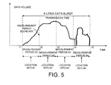
- Figure 5 illustrates one embodiment of throughput measurement with location information correlation.
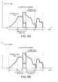
- Figure 6A illustrates one embodiment of MDT throughput measurement during connection interruptions.
- Figure 6B illustrates another embodiment of MDT throughput measurement during connection interruptions.
- Figure 7 illustrates a method of throughput measurement and MDT logging performed at an eNodeB.
- Figure 8 illustrates a method of throughput measurement and MDT logging performed at a UE.
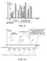
- Figure 9 illustrates one example of physical layer throughput measurement using TTI as measurement period.
- Figure 10 illustrates another example of physical layer throughput measurement using TTI as measurement period.
- Figure 11 illustrates an example of measuring bit rate per radio resource for a certain user.
- Figure 12 illustrates post processing for physical layer throughput measurement.
- Figure 13 is a flow chart of a method of throughput measurement for MDT from eNodeB perspective.
- Figure 14 is a flow chart of a method of providing MDT support information for throughput measurement from UE perspective.
- Figure 15 is a flow chart of a method of throughput measurement for MDT from UE perspective.
- FIG. 1 illustrates a method of throughput measurement for minimization of drive test (MDT) in a mobile communication network 100 in accordance with one novel aspect.
- Mobile communication network 100 comprises a user equipment UE 101 and base stations eNB 102-104.
- UE 101 is initially served by base station eNB 102 and is configured to provide supporting information for minimization of drive test (MDT).
- MDT UE 101 may perform various measurements and report measurement results to its serving eNB 102.
- For immediate MDT measurements are performed by the UE 101 in RRC_CONNECTED state. The collected information is available to be reported to the network immediately.
- Throughput measurement is one of QoS measurements that indicate the Quality of Service (QoS) of a radio link over the air interface.
- QoS Quality of Service
- the throughput of a radio link is equal to the data volume over a measurement period.
- the data traffic during minimization of drive test is uncontrollable and highly unpredictable.
- the applications e.g., web browsing, file transferring, etc.
- the data traffic typically contains many data bursts, each data burst separated by various idle periods. Therefore, traditional throughput definition for manual drive test is no longer suitable for throughput during minimization of drive test.
- the throughput measurement for MDT is defined as the data volume over multiple measurement periods, where the idle periods are removed from the measurement periods.
- the throughput for MDT is measured as data volume over an active time that includes time when there is data buffered for the measured UE, thus removing idle periods when no data is transmitted or buffered for the measured UE.
- the throughput measurement for MDT is measured as data volume over each physical layer transmission interval (TTI), thus removing idle periods by not taking into account non-used TTIs or re-transmission TTIs.
- TTI physical layer transmission interval
- eNB 102 measures the data volume for data burst 111 over multiple measurement periods (e.g., measurement period 112), when there is data buffered for UE 101. Each measurement period is associated with a measurement result. Furthermore, the throughput measurement results are logged and correlated with location information. The usage of measurement period allows location to be correlated with measurement results also for very long data bursts, e.g. continuous downloads.
- MDT logging is performed by the network, UE 101 provides location information to its serving eNB 102 such that the network can perform the correlation. Later on, when connection interruption occurs (e.g., UE 101 handovers from source eNB 102 to target eNB 104), throughput measurements are continued. Measurement and MDT logging configuration is forwarded from source eNB 102 to target eNB 104, and UE 101 may estimate the interruption time and provide the estimated interruption time to the network for consideration.
- connection interruption e.g., UE 101 handovers from source eNB 102 to target eNB
- FIG. 2 illustrates simplified block diagrams of a user equipment UE 201 and a base station eNodeB 231 in accordance with one novel aspect.
- UE 201 comprises memory 211, a processor 212, an MDT logging module 213 that performs MDT measurements/logging/reporting, a location module 214 that provides location information, and a radio frequency (RF) module 215 coupled to an antenna 216 for transmitting and receiving radio signals.
- serving eNodeB 211 comprises memory 241, a processor 242, an MDT logging module 243 that performs MDT throughput measurement and MDT logging, and a radio frequency (RF) module 246 coupled to an antenna 247 for transmitting and receiving radio signals.
- RF radio frequency
- the different modules are function modules that can be implemented by software, firmware, hardware, or any combination thereof.
- the function modules when executed by the processors 212 and 242 (e.g., via program instructions contained in memory 211 and 241), allow UE 201 and eNodeB 231 to perform MDT throughput measurements and MDT logging with location information correlation.
- L2-centric throughput measurement data volume is measured for each data burst by removing the idle periods between two consecutive data bursts. Assume that the wireless hop is the narrowest link in the network.
- the L2-centric measurement would reflect the throughput limitation imposed by the wireless hop on bandwidth-elastic applications, taking into account all RF, RRM and load constraints.
- One issue of the L2-centric method is the detection of the end of each data burst. This is particularly problematic if the throughput is measured for a certain application, for a certain bearer or a group of bearers, e.g. all bearers of a QoS class.
- One way of detecting the end of a data burst is by detecting whether there is still data buffered for the measured UE or the measured bearer(s). Because the data buffers exist at the transmitting side, it would be easy for the transmitter to make such detection. However, if throughput measurement is performed at the receiving side, then the receiver needs to detect whether there is data buffered for the measured UE at the transmitting side.
- Figure 3 illustrates one embodiment of detection of end of a data burst at the receiver side.
- the end of a data burst is detected by the receiver using an explicit end-marker sent from the transmitter.
- a first data burst #1 (from time t1 to t2) is followed by a second data burst #2 (from time t3 to t4).
- the transmitter sends an explicit end marker.
- the end-marker is sent by the eNodeB to assist the UE performing the throughput measurement.
- the end-marker is sent by the UE to assist the eNodeB performing the throughput measurement.
- the end-marker is contained in a Medium Access Control (MAC) extension that is either a separate Boolean bit or a Buffer status report (BSR) indicating zero data volume.
- MAC Medium Access Control
- BSR Buffer status report
- Figure 4 illustrates another embodiment of detection of end of a data burst at the receiver side.
- the end of a data burst is detected by the receiver by the absence of a following data transmission for an absent time duration.
- a first data burst #1 (from time t1 to t2) is followed by a second data burst #2 (from time t3 to t6). While data burst #1 and data burst #2 are separated by a relatively longer time gap (from time t2 to t3), data burst #2 contains a shorter time gap (from time t4 to t5).
- T To detect the end time t2 of data burst #1, the receiver determines whether there is more data transmission for an absent time duration T.
- the receiver Because there is no data transmission from time t2 and t3, and the time gap from t2 to t3 is larger than the absent time duration T, the receiver is able to detect that time t2 is the end of data burst #1.
- the receivers is able to determine that time t4 is not the end of data burst #2. Instead, the time gap from t4 to t5 is likely to be a small scheduling gap during data burst #2.
- a second issue of L2-centric throughput measurement is how to properly correlation measurement results with location information of the measured UE.
- location information e.g., GNSS information
- GNSS information that is available during the active time
- location information that was available during the start of active time could be logged, or location information that becomes available during the active time could be logged.
- the UE may move, it would be good to avoid usage of location information that is too old, e.g., by not including too old location information, or by providing separate time stamps for location information in logs, e.g., based on GNSS time.
- UE battery usage Another important aspect of location acquisition is resource usage, e.g. UE battery usage.
- resource usage e.g. UE battery usage.
- UEs may stay very long times in connected mode without transferring large amounts of data, to efficiently handle background traffic caused by social applications such as Skype or Facebook.
- performing periodic positioning for a UE during all connected time would consume many resources.
- throughput and other QoS measurements it is only interesting to log UE location when the QoS measurement is done, a lot of resource consumption saving could be done by only acquiring location while there is user plane traffic or during the transmission time of a data burst.
- the network provides an end-marker to the UE indicating the end of a downlink data-burst, meaning that if there is no uplink activity, then the UE may stop providing location information.
- the downlink end-marker may have the explicit meaning that this is the end of a data burst, or it may have the explicit meaning that the network commands the UE to stop providing MDT assistance information that is related to the Downlink data transmission.
- the measurements may be split in time domain such that multiple data volume during active time measurement results are provided, each measurement result applicable for a certain time duration, and for each of the said time durations in time domain, location information or information from which location information can be deduced can be provided.
- the time duration is equivalent and is referred to as the measurement period.
- the long data burst is split at each measurement period boundary, and data volume is measured. As a result, measurement result is generated for each measurement period, which can be correlated with location information.
- Figure 5 illustrates one embodiment of throughput measurement with location information correlation.
- a long data burst starts at time t1 and ends at time t5 during a transmission time.
- the entire transmission time from t1 to t5 is then split into four measurement periods in time domain.
- the data burst is also split at each measurement period boundary (e.g., at time t2).
- L2 upper SAP can be used to determine which bits to count. If measurement is performed in the transmitting end, then HARQ ACK can be used to determine successful transmission.
- the UE typically selectively provides location information during the transmission time of the data burst, when data is being transmitted, buffered for transmission, received, or until the UE receives an end-marker. For example, the UE provides location information #1 during measurement period #1, provides location information #2 during measurement period #2, and so on so forth.
- the time stamp information could be implicit, e.g., the first measurement period of each data burst has a time stamp, the measurement period may be fixed and corresponding time stamp could be deduced.
- the measurement periods do not need to coincide with the data transmission active time. For measurement periods with no data transmission activity, no data rate and no location information need to be logged.
- Each measurement period is either triggered periodically, with the periodical time being configurable, or triggered based on a radio condition change, a link adaptation change, or a mobility event. If the average preconditions for a certain throughput stays the same, and the location has not changed a lot, then there is no need to stop/start a new measurement period.
- the determination of start/stop of a logging duration should be configurable.
- the start and stop boundaries of a measurement period may be indicated by a time stamp, or a simplified time stamp, e.g., a measurement period counter.
- the start and stop boundaries can be known a priori, e.g., they may be Modulo-N based on system frame number (SFN), and the time stamp of location information may be sufficient to infer the measurement period timing.
- SFN system frame number
- connection interruptions include mobility when UE changes cell (e.g., handover, redirection), connection failure (e.g., radio link failure, handover failure, RRC re-establishment failure followed by a connection recovery, e.g., RRC re-establishment, e.g., NAS-triggered recovery).
- connection failure e.g., radio link failure, handover failure, RRC re-establishment failure followed by a connection recovery, e.g., RRC re-establishment, e.g., NAS-triggered recovery.
- MDT throughput measurement is continued at connection interruptions. The idea is that measurements shall continue as before the connection interruption to create a good view of what was the impact of the connection interruption to the user perceived data throughput, e.g., what is the TCP impact.
- connection interruption impact to QoS measurements is always taken into account.
- the interruption time In case it is difficult to include the interruption time, and the actual interruption time is short, it could be counted separately or even removed from the measurement period count.
- One simple implementation is to stop one measurement period at the connection failure, and to start the next measurement period when connection has been recovered.
- Figure 6A illustrates one embodiment MDT throughput measurement during connection interruptions, where measurement is continued.
- a long data burst starts at time t1 and ends at time t5.
- the entire active time from t1 to t5 is then split into four measurement periods in time domain.
- a connection interruption occurs during measurement period #2.
- Throughput measurement is continued for the connection interruption. If the measurement is performed at the UE, the measurement period just continues as long as there are data in the buffers regardless UE state changes.
- UE continues the measurement period, e.g., based on SFN of the cell where the UE received measurement configuration, or synchronize to new cell SFN resulting in irregular measurement periods at cell changes.
- Figure 6B illustrates another embodiment MDT throughput measurement during connection interruptions, where measurement is restarted.
- Figure 6B is very similar to Figure 6A .
- connection interruption occurs at time t2', however, measurement is stopped and restarted after the interruption at time t3.
- Such method would actually capture TCP congestion reactions on the connection interruption, e.g., for handover implicitly by change of serving cell, for RRC re-establishment or NAS-triggered recovery, as such events could be indicated explicitly in the log.
- Providing the interruption time and interruptions and log those separately would allow for the post processing system to take interruptions into account flexibly in several ways.
- the new radio access radio network node needs to know what measurements to start, and the parameters needed to configure the measurements correctly. Furthermore, at cell change or handover, or other connection interruption (RRC re-establishment), the UE estimates the interruption time caused by the interruption. The UE then provides the interruption time to the RAN to be taken into account.
- RRC re-establishment the interruption time caused by the interruption. The UE then provides the interruption time to the RAN to be taken into account.
- FIG. 7 illustrates a method of throughput measurement and MDT logging performed at an eNodeB in a mobile communication network.
- RAN 702 starts to perform MDT throughput measurement and MDT logging of bit rates, data volumes, and/or times for a data burst that having an active time from t1 to t2.
- the measurement is split into multiple measurement periods in time domain, and each measurement period is associated with a measurement result.
- UE 701 reports location information for each measurement period (e.g., in steps 721, 722 and 723) and the network correlates the throughput measurement with the location information.
- UE 701 stops provide location information after the end of the data burst or data transmission is not ongoing. For measurement periods with no data transmission activity, no data rate and no location information need to be logged.
- FIG. 8 illustrates a method of throughput measurement and MDT logging performed at a UE in a mobile communication network.
- UE 801 starts to perform MDT throughput measurement and MDT logging of bit rates, data volumes, and/or times for a data burst that having an active time from t1 to t2.
- the measurement is split into multiple measurement periods in time domain, and each measurement period is associated with a measurement result.
- UE 801 also logs location information for each measurement period (e.g., in steps 821, 822, and 823).
- step 831 UE 801 terminates MDT logging and location features (e.g., when MDT session expires).
- Location information only needs to be provided and logged when throughput measurement is active, e.g., when transmission is ongoing or data is being buffered. If MDT throughput measurement is not applicable, then related MDT features could be disabled, e.g., location features could be turned off.
- the L2-centric throughput measurement is based on the assumption that the wireless hop is the most narrowband link in the network. If there are other significant bottlenecks than the wireless link, then each transmission may result in emptying the data buffers.
- data buffer is emptied in one TTI transmission, such transmission is referred to as a single TTI transmission.
- the single TTI transmissions (not counting HARQ retransmissions) are excluded from the throughput measurement result.
- those single TTI transmission are taken into account separately, e.g., by logging data volume and/or explicitly counting or logging each such single TTI transmissions.
- L1-centric solutions may be applied.
- data volume is measured for each transmission time interval (TTI).
- the transmitted or received data volume or throughput includes radio layer 2 overhead, i.e., MAC layer, RLC layer, and PDCP layer overhead.
- the data volume per TTI measurement is also correlated with UE location information or measurements from which it is possible to derive UE location.
- FIG 9 illustrates one example of physical layer throughput measurement using TTI as measurement period.
- non-used TTIs are excluded from the measurement results. That way, idle L1 radio resources are removed for the measured UE.
- re-transmission TTIs e.g., TTIs 902 and 903 are excluded from the measurement results. Only original transmission TTIs (e.g., TTI 901) are taken into account in the measurement results.
- Figure 10 illustrates another example of physical layer throughput measurement using TTI as measurement period.
- the transmission eventually fails (e.g., upon a third NACK, transmission is aborted), then the original transmission TTI 1001 and all the re-transmission TTIs 1002 and 1003 should not contribute to the measurement results.
- Figure 11 illustrates an example of measuring bit rate per radio resource for a certain user.
- the data volume per TTI measurement can be further divided per radio resource, to represent Layer 1 radio resource efficiency.
- the radio resource would typically be a physical resource block (PRB) or part of PRB.
- PRB physical resource block
- the data volume is divided per PRBs to reflect bits/PRB efficiency.
- WCDMA WCDMA systems
- the data volume may be divided per orthogonal spreading factor reflecting how big part of the code tree resource is used for the data transmission.
- the resource usage is divided by the number of users using it, e.g., for multi-user MIMO, if a PRB is used by two users, then each uses a half PRB.
- each subframe in frame N is a TTI, which contains multiple PRBs.
- PRB#1 is for user 1
- PRB#2 is for user 2 for MU-MIMO transmission.
- Figure 12 illustrates post processing for physical layer throughput measurement.
- data volume or throughput per intervals is process statistically to form a Probability density function (PDF).
- PDF Probability density function
- data volume or throughput is process statistically in the form of average, variance or deviation.
- the processing period is adaptable so that it maps to UE in one location, i.e., an area for which the throughput or data volume measurement is interesting.
- FIG. 13 is a flow chart of a method of throughput measurement from eNodeB perspective.
- a base station eNodeB
- RRC radio resource control
- UE user equipment
- the base station measures transmitted or received data volume during a transmission time of a data burst between the base station and the UE.
- the data burst spans multiple measurement periods and the data burst is split at each measurement period boundary.
- data volume is measure to generate a corresponding measurement result.
- the base station receives location information from the UE such that each measurement result can be correlated with location information.
- FIG 14 is a flow chart of a method of providing MDT support information for throughput measurement from UE perspective.
- a user equipment UE establishes a radio resource control (RRC) connection with a base station (eNodeB) in a radio access network (RAN).
- RRC radio resource control
- eNodeB base station
- RAN radio access network
- the UE transmits or receives data traffic.
- the UE provides MDT support information to the RAN, the eNodeB, or to a radio network controller (RNC).
- the MDT support information is related to throughput measurement of the transmitted or received data.
- the MDT support information comprises location information during the transmission time of the data burst when data is being transmitted, buffered for transmission, being received, or until the UE receives an end-marker from the RAN.
- the MDT support information comprises an end-marker to indicate the end of a data burst.
- the UE estimates the interruption time caused by a connection interruption, and the MDT support information comprises the estimated interruption time forwarded to a target eNodeB for consideration.
- FIG. 15 is a flow chart of a method of throughput measurement for MDT from UE perspective.
- a user equipment UE
- eNodeB base station
- the UE measures transmitted or received data volume during a transmission time of a data burst between the base station and the UE.
- the data burst spans multiple measurement periods and the data burst is split at each measurement period boundary.
- data volume is measure to generate a corresponding measurement result.
- each measurement result is logged with time stamp so that it can be correlated with location information.
Landscapes
- Engineering & Computer Science (AREA)
- Computer Networks & Wireless Communication (AREA)
- Signal Processing (AREA)
- Mobile Radio Communication Systems (AREA)
Abstract
Description
- This application claims priority under 35 U.S.C. §119 from
U.S. Provisional Application Number 61/542,395 - The disclosed embodiments relate generally to QoS verification throughput measurement by minimization of drive test (MDT), and, more particularly, to throughput measurement that fulfills MDT requirements at minimum complexity.
- The 3rd Generation Partnership Project (3GPP) long term evolution (LTE) system, introduced as 3GPP release 8, is an improved universal mobile telecommunication system (UMTS). An LTE system offers high peak data rates, low latency, improved system capacity, and low operating cost resulting from simple network architecture. In the LTE system, an evolved universal terrestrial radio access network (E-UTRAN) includes a plurality of evolved Node-Bs (eNBs) communicating with a plurality of mobile stations, referred as user equipment (UE). 3GPP introduces new features to help LTE system operators to further optimize network planning in a cost-effective way. Minimization of Drive Test (MDT) is one of the features where UEs collect measurements and report measurement information to their serving eNBs.
- MDT has been worked on in 3GPP to help with network optimization. Network optimization is traditionally done by manual drive testing, which is costly and causes additional CO2 emissions. The essence of MDT feature is to provide for normal mobile terminals the possibility to record and log information relevant to the radio communication of the mobile terminals, correlated with the geographical location of the mobile terminals. MDT feature enables UEs to perform Operations, Administration, and Maintenance (OAM) activities, such as neighborhood detection, measurements, logging and recording for OAM purposes, which includes radio resource management (RRM) and optimization purposes.
- While studying the possible scope of minimization of drive test (e.g., 3GPP TR 36.805), it has been found beneficial to include Quality of Service (QoS) measurements for MDT, and in particular a throughput measurement. It is assumed that it would be desirable to as much as possible mimic manual drive testing. It would be desirable to provide the possibility to measure throughput, and while the UE pass through a network doing frequent handovers. Note that it is expected that frequent handover may affect TCP performance and lead to reduced user-experienced throughput.
- Several definitions of throughput measurements exist in 3GPP TR36.314, TR 32.425, and TR 32.451. However, there is no definition supports well all the MDT requirements.
It is an objective of the current invention to propose a throughput measurement definition, which fulfills well all the MDT requirements with minimum complexity. - A method of throughput and data volume measurement for minimization of drive test (MDT) is proposed. A base station establishes a radio resource control (RRC) connection with a user equipment (UE) in a mobile communication network. The network is configured for MDT, and the UE may be configured for MDT. The base station or UE measures transmitted or received data volume during a transmission time of a data burst between the base station and the UE. When the data burst spans multiple measurement periods, the data burst is split at each measurement period boundary. For each measurement period, data volume during the measurement period time is measured to generate a measurement result. When throughput measurement is performed by the network, the base station receives location information that is available during the transmission time of the data burst. The data volume measurement during the measurement period is logged with time stamp such that each measurement result can be correlated with the location information or other measurements and system configuration from which location information can be deduced.
- In one novel aspect, the throughput measurement for MDT is defined as the data volume over multiple measurement periods, where the idle periods are removed from the measurement periods. In one embodiment (e.g., layer-2 L2-centric), the throughput for MDT is measured as data volume over an active time that includes time when there is data buffered for the measured UE, thus removing idle periods when no data is transmitted or buffered for the measured UE. In another embodiment (e.g., layer-1 L1-centric), the throughput measurement for MDT is measured as data volume over each physical layer transmission interval (TTI), thus removing idle periods by not taking into account non-used TTIs or re-transmission TTIs.
- In addition to provide location information, the UE may provide other MDT support information for throughput measurement performed by the network. In one embodiment, when throughput measurement is performed by an eNodeB for uplink transmission, the UE sends an explicit end-marker to the eNodeB to indicate the end of a data burst. In another embodiment, when throughput measurement is continued for connection interruptions, the UE estimates the interruption time and forwards the interruption time to a target eNodeB for consideration. In yet another embodiment, the UE selectively provides location information only during the transmission time of the data burst, defined for the uplink by the time when data is being transmitted or buffered, and defined for the downlink by the time when data is being transmitted and sometime after data transmission or until the UE has received an explicit burst end-marker from the network.
- Other embodiments and advantages are described in the detailed description below. This summary does not purport to define the invention. The invention is defined by the claims.
-
Figure 1 illustrates a method of throughput measurement for minimization of drive test (MDT) in accordance with one novel aspect. -
Figure 2 illustrates simplified block diagrams of a user equipment (UE) and a base station (eNodeB) in accordance with one novel aspect. -
Figure 3 illustrates one embodiment of detection of end of data burst at receiver side, by assistance from the transmitter, sending an end-marker. -
Figure 4 illustrates another embodiment of detection of end of data burst at receiver side. -
Figure 5 illustrates one embodiment of throughput measurement with location information correlation. -
Figure 6A illustrates one embodiment of MDT throughput measurement during connection interruptions. -
Figure 6B illustrates another embodiment of MDT throughput measurement during connection interruptions. -
Figure 7 illustrates a method of throughput measurement and MDT logging performed at an eNodeB. -
Figure 8 illustrates a method of throughput measurement and MDT logging performed at a UE. -
Figure 9 illustrates one example of physical layer throughput measurement using TTI as measurement period. -
Figure 10 illustrates another example of physical layer throughput measurement using TTI as measurement period. -
Figure 11 illustrates an example of measuring bit rate per radio resource for a certain user. -
Figure 12 illustrates post processing for physical layer throughput measurement. -
Figure 13 is a flow chart of a method of throughput measurement for MDT from eNodeB perspective. -
Figure 14 is a flow chart of a method of providing MDT support information for throughput measurement from UE perspective. -
Figure 15 is a flow chart of a method of throughput measurement for MDT from UE perspective. - Reference will now be made in detail to some embodiments of the invention, examples of which are illustrated in the accompanying drawings.
-
Figure 1 illustrates a method of throughput measurement for minimization of drive test (MDT) in amobile communication network 100 in accordance with one novel aspect.Mobile communication network 100 comprises a user equipment UE 101 and base stations eNB 102-104. UE 101 is initially served by base station eNB 102 and is configured to provide supporting information for minimization of drive test (MDT). During MDT, UE 101 may perform various measurements and report measurement results to its serving eNB 102. There are two types of MDT. For logged MDT, measurements are performed and logged by UE 101 in RRC_IDLE state.UE 101 may report the collected information to the network at a later point of time. For immediate MDT, measurements are performed by theUE 101 in RRC_CONNECTED state. The collected information is available to be reported to the network immediately. - Throughput measurement is one of QoS measurements that indicate the Quality of Service (QoS) of a radio link over the air interface. In general, the throughput of a radio link is equal to the data volume over a measurement period. Unlike manual drive test, however, the data traffic during minimization of drive test is uncontrollable and highly unpredictable. Depending on the applications (e.g., web browsing, file transferring, etc.) running on the UE, the data traffic typically contains many data bursts, each data burst separated by various idle periods. Therefore, traditional throughput definition for manual drive test is no longer suitable for throughput during minimization of drive test.
- In one novel aspect, the throughput measurement for MDT is defined as the data volume over multiple measurement periods, where the idle periods are removed from the measurement periods. In one embodiment (e.g., layer-2 L2-centric), the throughput for MDT is measured as data volume over an active time that includes time when there is data buffered for the measured UE, thus removing idle periods when no data is transmitted or buffered for the measured UE. In another embodiment (e.g., layer-1 L1-centric), the throughput measurement for MDT is measured as data volume over each physical layer transmission interval (TTI), thus removing idle periods by not taking into account non-used TTIs or re-transmission TTIs.
- In the example of
Figure 1 ,eNB 102 measures the data volume for data burst 111 over multiple measurement periods (e.g., measurement period 112), when there is data buffered forUE 101. Each measurement period is associated with a measurement result. Furthermore, the throughput measurement results are logged and correlated with location information. The usage of measurement period allows location to be correlated with measurement results also for very long data bursts, e.g. continuous downloads. When the MDT logging is performed by the network,UE 101 provides location information to its servingeNB 102 such that the network can perform the correlation. Later on, when connection interruption occurs (e.g.,UE 101 handovers fromsource eNB 102 to target eNB 104), throughput measurements are continued. Measurement and MDT logging configuration is forwarded fromsource eNB 102 to targeteNB 104, andUE 101 may estimate the interruption time and provide the estimated interruption time to the network for consideration. -
Figure 2 illustrates simplified block diagrams of auser equipment UE 201 and abase station eNodeB 231 in accordance with one novel aspect.UE 201 comprisesmemory 211, aprocessor 212, anMDT logging module 213 that performs MDT measurements/logging/reporting, a location module 214 that provides location information, and a radio frequency (RF)module 215 coupled to anantenna 216 for transmitting and receiving radio signals. Similarly, servingeNodeB 211 comprisesmemory 241, a processor 242, an MDT logging module 243 that performs MDT throughput measurement and MDT logging, and a radio frequency (RF) module 246 coupled to an antenna 247 for transmitting and receiving radio signals. The different modules are function modules that can be implemented by software, firmware, hardware, or any combination thereof. The function modules, when executed by theprocessors 212 and 242 (e.g., via program instructions contained inmemory 211 and 241), allowUE 201 andeNodeB 231 to perform MDT throughput measurements and MDT logging with location information correlation. - In L2-centric throughput measurement, data volume is measured for each data burst by removing the idle periods between two consecutive data bursts. Assume that the wireless hop is the narrowest link in the network. The L2-centric measurement would reflect the throughput limitation imposed by the wireless hop on bandwidth-elastic applications, taking into account all RF, RRM and load constraints. One issue of the L2-centric method is the detection of the end of each data burst. This is particularly problematic if the throughput is measured for a certain application, for a certain bearer or a group of bearers, e.g. all bearers of a QoS class. One way of detecting the end of a data burst is by detecting whether there is still data buffered for the measured UE or the measured bearer(s). Because the data buffers exist at the transmitting side, it would be easy for the transmitter to make such detection. However, if throughput measurement is performed at the receiving side, then the receiver needs to detect whether there is data buffered for the measured UE at the transmitting side.
-
Figure 3 illustrates one embodiment of detection of end of a data burst at the receiver side. In this embodiment, the end of a data burst is detected by the receiver using an explicit end-marker sent from the transmitter. In the example ofFigure 3 , a first data burst #1 (from time t1 to t2) is followed by a second data burst #2 (from time t3 to t4). Taking data burst #1 as an example, for accurate throughput measurement, the data volume of data burst #1 is measured over the active time from time t1 to t2, which produces a measurement result of data rate for measurement period T = t2-t1. That is, Data Rate = Data volume V / Measurement Period T, where V = received data volume (L2 upper SAP), T = t2-t1, where t1 = TTI when first piece ofdata burst # 1 begins reception, and t2 = TTI when last piece ofdata burst # 1 is successfully received, or when transmission of the last piece ofdata burst # 1 is given up. In order for the receiver to know the exact time t2 of the end of data burst #1, the transmitter sends an explicit end marker. For downlink measurement performed at the UE, the end-marker is sent by the eNodeB to assist the UE performing the throughput measurement. For uplink measurement performed at the eNodeB, the end-marker is sent by the UE to assist the eNodeB performing the throughput measurement. In one specific example, the end-marker is contained in a Medium Access Control (MAC) extension that is either a separate Boolean bit or a Buffer status report (BSR) indicating zero data volume. -
Figure 4 illustrates another embodiment of detection of end of a data burst at the receiver side. In this embodiment, the end of a data burst is detected by the receiver by the absence of a following data transmission for an absent time duration. In the example ofFigure 4 , a first data burst #1 (from time t1 to t2) is followed by a second data burst #2 (from time t3 to t6). While data burst #1 and data burst #2 are separated by a relatively longer time gap (from time t2 to t3), data burst #2 contains a shorter time gap (from time t4 to t5). To detect the end time t2 ofdata burst # 1, the receiver determines whether there is more data transmission for an absent time duration T. Because there is no data transmission from time t2 and t3, and the time gap from t2 to t3 is larger than the absent time duration T, the receiver is able to detect that time t2 is the end of data burst #1. On the other hand, fordata burst # 2, although there is no data transmission from time t4 to t5, but because the time gap from t4 to t5 is smaller than the absent time duration T, the receivers is able to determine that time t4 is not the end of data burst #2. Instead, the time gap from t4 to t5 is likely to be a small scheduling gap duringdata burst # 2. - A second issue of L2-centric throughput measurement is how to properly correlation measurement results with location information of the measured UE. In order to correlate MDT throughput measurement with location information, detailed location information, e.g., GNSS information, that is available during the active time is provided for logging and logged. For example, location information that was available during the start of active time could be logged, or location information that becomes available during the active time could be logged. Furthermore, because the UE may move, it would be good to avoid usage of location information that is too old, e.g., by not including too old location information, or by providing separate time stamps for location information in logs, e.g., based on GNSS time.
- Another important aspect of location acquisition is resource usage, e.g. UE battery usage. In the current era of increasingly popular smart-phones, UEs may stay very long times in connected mode without transferring large amounts of data, to efficiently handle background traffic caused by social applications such as Skype or Facebook.
In such scenarios, performing periodic positioning for a UE during all connected time would consume many resources. As for throughput and other QoS measurements, it is only interesting to log UE location when the QoS measurement is done, a lot of resource consumption saving could be done by only acquiring location while there is user plane traffic or during the transmission time of a data burst. In one embodiment, the network provides an end-marker to the UE indicating the end of a downlink data-burst, meaning that if there is no uplink activity, then the UE may stop providing location information. The downlink end-marker may have the explicit meaning that this is the end of a data burst, or it may have the explicit meaning that the network commands the UE to stop providing MDT assistance information that is related to the Downlink data transmission. - To handle data transmissions with long active times, the measurements may be split in time domain such that multiple data volume during active time measurement results are provided, each measurement result applicable for a certain time duration, and for each of the said time durations in time domain, location information or information from which location information can be deduced can be provided. Here, the time duration is equivalent and is referred to as the measurement period. For each measurement period, the long data burst is split at each measurement period boundary, and data volume is measured. As a result, measurement result is generated for each measurement period, which can be correlated with location information.
-
Figure 5 illustrates one embodiment of throughput measurement with location information correlation. In the example ofFigure 5 , a long data burst starts at time t1 and ends at time t5 during a transmission time. The entire transmission time from t1 to t5 is then split into four measurement periods in time domain. The data burst is also split at each measurement period boundary (e.g., at time t2). For example, during measurement period #1 (T1 = t2-t1), the data volume V1 of the data burst from t1 to t2 is measured and a first measurement result is calculated, e.g.Data Rate # 1 = (Data volume V1) / (Measurement Period T1). Similarly, during measurement period #2 (T2 = t3-t2), the data volume V2 of the data burst from t2 to t3 is measured and a second measurement result is calculated, e.g.Data Rate # 2 = (Data volume V2) / (Measurement Period T1). Same formeasurement periods # 3 and #4. - For each measurement period (e.g., measurement period #1), the data volume V1 and time T1 need to start/stop at the measurement period start/stop. For example, T1 = t2-t1, where t1 = TTI when first piece of a data burst begins transmission/reception, or first TTI of measurement period when data is buffered in L2 and transmission of data burst has begun; t2 = TTI when last piece of data burst successfully received, or last TTI of measurement period when data is buffered in L2 and transmission of data burst has begun; V = data volume successfully received or transmitted for a data burst during measurement period. L2 upper SAP can be used to determine which bits to count. If measurement is performed in the transmitting end, then HARQ ACK can be used to determine successful transmission.
- Typically, for MDT, it is needed to be able to correlate each measurement period with location information and with time stamp information. In General, the UE only selectively provides location information during the transmission time of the data burst, when data is being transmitted, buffered for transmission, received, or until the UE receives an end-marker. For example, the UE provides
location information # 1 duringmeasurement period # 1, provideslocation information # 2 duringmeasurement period # 2, and so on so forth. The time stamp information could be implicit, e.g., the first measurement period of each data burst has a time stamp, the measurement period may be fixed and corresponding time stamp could be deduced. The measurement periods do not need to coincide with the data transmission active time. For measurement periods with no data transmission activity, no data rate and no location information need to be logged. - Each measurement period is either triggered periodically, with the periodical time being configurable, or triggered based on a radio condition change, a link adaptation change, or a mobility event. If the average preconditions for a certain throughput stays the same, and the location has not changed a lot, then there is no need to stop/start a new measurement period. For optimal logging, reduced size of log files, etc., the determination of start/stop of a logging duration should be configurable. However, for simplest possible implementation, the start and stop boundaries of a measurement period may be indicated by a time stamp, or a simplified time stamp, e.g., a measurement period counter. Alternatively, the start and stop boundaries can be known a priori, e.g., they may be Modulo-N based on system frame number (SFN), and the time stamp of location information may be sufficient to infer the measurement period timing.
- Note that when splitting a data burst into several time durations, it is not evident how to determine to what time duration a data volume belongs. It is proposed to have a simple criterion such that data that has been successfully received or successfully transmitted as indicated by HARQ ACK during a measurement period is included in the data volume measurement for that measurement period. Having a criteria based on successful reception of data based on HARQ ACK comes with several advantages, such as easy interpretation and that definition is consistent with the ending time duration of a data burst when all data has been transmitted.
- A third issue of L2-centric throughput measurement is handling connection interruptions during measurement. Connection interruptions include mobility when UE changes cell (e.g., handover, redirection), connection failure (e.g., radio link failure, handover failure, RRC re-establishment failure followed by a connection recovery, e.g., RRC re-establishment, e.g., NAS-triggered recovery). It is proposed that MDT throughput measurement is continued at connection interruptions. The idea is that measurements shall continue as before the connection interruption to create a good view of what was the impact of the connection interruption to the user perceived data throughput, e.g., what is the TCP impact. For regular drive testing where the throughput measurement is always performed in the UE, and on the IP layer, connection interruption impact to QoS measurements is always taken into account. In case it is difficult to include the interruption time, and the actual interruption time is short, it could be counted separately or even removed from the measurement period count. One simple implementation is to stop one measurement period at the connection failure, and to start the next measurement period when connection has been recovered.
-
Figure 6A illustrates one embodiment MDT throughput measurement during connection interruptions, where measurement is continued. In the example ofFigure 6A , a long data burst starts at time t1 and ends at time t5. The entire active time from t1 to t5 is then split into four measurement periods in time domain. However, duringmeasurement period # 2, a connection interruption occurs. Throughput measurement is continued for the connection interruption. If the measurement is performed at the UE, the measurement period just continues as long as there are data in the buffers regardless UE state changes. UE continues the measurement period, e.g., based on SFN of the cell where the UE received measurement configuration, or synchronize to new cell SFN resulting in irregular measurement periods at cell changes. -
Figure 6B illustrates another embodiment MDT throughput measurement during connection interruptions, where measurement is restarted.Figure 6B is very similar toFigure 6A . When connection interruption occurs at time t2', however, measurement is stopped and restarted after the interruption at time t3. Such method would actually capture TCP congestion reactions on the connection interruption, e.g., for handover implicitly by change of serving cell, for RRC re-establishment or NAS-triggered recovery, as such events could be indicated explicitly in the log. Providing the interruption time and interruptions and log those separately would allow for the post processing system to take interruptions into account flexibly in several ways. - If throughput measurement is performed at the network side, then at inter-node handover preparation, measurement and logging configuration is forwarded from source eNodeB to target eNodeB. In order to continue or restart measurement at handover, the new radio access radio network node needs to know what measurements to start, and the parameters needed to configure the measurements correctly. Furthermore, at cell change or handover, or other connection interruption (RRC re-establishment), the UE estimates the interruption time caused by the interruption. The UE then provides the interruption time to the RAN to be taken into account.
-
Figure 7 illustrates a method of throughput measurement and MDT logging performed at an eNodeB in a mobile communication network. Instep 711,RAN 702 starts to perform MDT throughput measurement and MDT logging of bit rates, data volumes, and/or times for a data burst that having an active time from t1 to t2. During the active time, the measurement is split into multiple measurement periods in time domain, and each measurement period is associated with a measurement result. When MDT throughput measurement is performed byRAN 702, it is sufficient thatUE 701 reports location information for each measurement period (e.g., insteps UE 701 stops provide location information after the end of the data burst or data transmission is not ongoing. For measurement periods with no data transmission activity, no data rate and no location information need to be logged. -
Figure 8 illustrates a method of throughput measurement and MDT logging performed at a UE in a mobile communication network. Instep 811,UE 801 starts to perform MDT throughput measurement and MDT logging of bit rates, data volumes, and/or times for a data burst that having an active time from t1 to t2. During the active time, the measurement is split into multiple measurement periods in time domain, and each measurement period is associated with a measurement result.UE 801 also logs location information for each measurement period (e.g., insteps step 831,UE 801 terminates MDT logging and location features (e.g., when MDT session expires). Location information only needs to be provided and logged when throughput measurement is active, e.g., when transmission is ongoing or data is being buffered. If MDT throughput measurement is not applicable, then related MDT features could be disabled, e.g., location features could be turned off. - The L2-centric throughput measurement is based on the assumption that the wireless hop is the most narrowband link in the network. If there are other significant bottlenecks than the wireless link, then each transmission may result in emptying the data buffers. When data buffer is emptied in one TTI transmission, such transmission is referred to as a single TTI transmission. In such a scenario, the single TTI transmissions (not counting HARQ retransmissions) are excluded from the throughput measurement result. Alternatively, those single TTI transmission are taken into account separately, e.g., by logging data volume and/or explicitly counting or logging each such single TTI transmissions.
- In addition to L2-centric throughput measurement, L1-centric solutions may be applied. For L1-centric measurement, data volume is measured for each transmission time interval (TTI). The transmitted or received data volume or throughput includes
radio layer 2 overhead, i.e., MAC layer, RLC layer, and PDCP layer overhead. The data volume per TTI measurement is also correlated with UE location information or measurements from which it is possible to derive UE location. -
Figure 9 illustrates one example of physical layer throughput measurement using TTI as measurement period. In the example ofFigure 9 , non-used TTIs are excluded from the measurement results. That way, idle L1 radio resources are removed for the measured UE. In addition, re-transmission TTIs (e.g.,TTIs 902 and 903) are excluded from the measurement results. Only original transmission TTIs (e.g., TTI 901) are taken into account in the measurement results. -
Figure 10 illustrates another example of physical layer throughput measurement using TTI as measurement period. In the example ofFigure 10 , fororiginal transmission TTI 1001, if the transmission eventually fails (e.g., upon a third NACK, transmission is aborted), then theoriginal transmission TTI 1001 and all there-transmission TTIs -
Figure 11 illustrates an example of measuring bit rate per radio resource for a certain user. The data volume per TTI measurement can be further divided per radio resource, to representLayer 1 radio resource efficiency. In LTE systems, the radio resource would typically be a physical resource block (PRB) or part of PRB. Thus, data volume is divided per PRBs to reflect bits/PRB efficiency. In WCDMA systems, the data volume may be divided per orthogonal spreading factor reflecting how big part of the code tree resource is used for the data transmission. In case a PRB is used for multiple users, the resource usage is divided by the number of users using it, e.g., for multi-user MIMO, if a PRB is used by two users, then each uses a half PRB. In the example ofFigure 11 , each subframe in frame N is a TTI, which contains multiple PRBs. In one example,PRB# 1 is foruser 1 andPRB# 2 is foruser 2 for MU-MIMO transmission. - For L1-centric data volume per TTI or data volume per radio resource measurement, if many data samples were available for a certain location, then the recorded amount of data would be very large and difficult to interpret. In this scenario, post processing could be done, to distill representations that are easier to understand and for which they are more compressed data representation.
-
Figure 12 illustrates post processing for physical layer throughput measurement. Inchart 1210, data volume or throughput per intervals is process statistically to form a Probability density function (PDF). Inchart 1220, data volume or throughput is process statistically in the form of average, variance or deviation. The processing period is adaptable so that it maps to UE in one location, i.e., an area for which the throughput or data volume measurement is interesting. -
Figure 13 is a flow chart of a method of throughput measurement from eNodeB perspective. Instep 1301, a base station (eNodeB) establishes a radio resource control (RRC) connection with a user equipment (UE) in a mobile communication network. Instep 1302, the base station measures transmitted or received data volume during a transmission time of a data burst between the base station and the UE. The data burst spans multiple measurement periods and the data burst is split at each measurement period boundary. For each measurement period, data volume is measure to generate a corresponding measurement result. The base station receives location information from the UE such that each measurement result can be correlated with location information. -
Figure 14 is a flow chart of a method of providing MDT support information for throughput measurement from UE perspective. Instep 1401, a user equipment (UE) establishes a radio resource control (RRC) connection with a base station (eNodeB) in a radio access network (RAN). Instep 1402, the UE transmits or receives data traffic. Instep 1403, the UE provides MDT support information to the RAN, the eNodeB, or to a radio network controller (RNC). The MDT support information is related to throughput measurement of the transmitted or received data. In one embodiment, the MDT support information comprises location information during the transmission time of the data burst when data is being transmitted, buffered for transmission, being received, or until the UE receives an end-marker from the RAN. In another embodiment, the MDT support information comprises an end-marker to indicate the end of a data burst. In yet another embodiment, the UE estimates the interruption time caused by a connection interruption, and the MDT support information comprises the estimated interruption time forwarded to a target eNodeB for consideration. -
Figure 15 is a flow chart of a method of throughput measurement for MDT from UE perspective. Instep 1501, a user equipment (UE) establishes a radio resource control (RRC) connection with a base station (eNodeB) in a mobile communication network. Instep 1502, the UE measures transmitted or received data volume during a transmission time of a data burst between the base station and the UE. The data burst spans multiple measurement periods and the data burst is split at each measurement period boundary. For each measurement period, data volume is measure to generate a corresponding measurement result. In one embodiment, each measurement result is logged with time stamp so that it can be correlated with location information. - Although the present invention has been described in connection with certain specific embodiments for instructional purposes, the present invention is not limited thereto. Accordingly, various modifications, adaptations, and combinations of various features of the described embodiments can be practiced without departing from the scope of the invention as set forth in the claims.
Claims (20)
- A method, comprising:establishing a radio resource control (RRC) connection by a base station with a user equipment (UE) in a mobile communication network; andmeasuring transmitted or received data volume during a transmission time of a data burst between the base station and the UE, wherein the data burst spans multiple measurement periods and the data burst is split at each measurement period boundary, and wherein each measurement period is associated with a measurement result.
- The method of Claim 1, wherein each measurement period is either triggered periodically or triggered based on a radio condition change, a link adaptation change, or a mobility event.
- The method of Claim 1, wherein the base station requests, receives and logs location information that is available during the transmission time of the data burst when data is being transmitted, buffered for transmission, received, or until the base-station receives an end-marker from the UE.
- The method of Claim 1, wherein the base station provides an end-marker to the UE together with a last piece of data in the downlink data burst.
- The method of Claim 1, wherein the base station receives an explicit end-marker together with a last piece of data in the uplink data burst.
- The method of Claim 1, wherein the data volume measurement is logged with time stamp such that each measurement result is correlated with location information.
- The method of Claim 1, wherein the measurements are continued at connection interruptions, and wherein measurement and logging information is forwarded by the base station to a target base station at handover preparation.
- The method of Claim 1, wherein the base station receives an estimated interruption time, wherein the interruption time is applicable to a handover, a RRC connection re-establishment, or a Non Access Stratum (NAS) triggered connection establishment after a connection failure.
- The method of Claim 1, wherein each measurement period corresponds to a physical layer (L1) time transmission interval (TTI).
- The method of Claim 9, wherein TTIs not used for the measured UE, retransmission TTIs, and failed TTIs for which transmission never succeeds do not contribute to the measurement results.
- The method of Claim 9, wherein the data volume includes radio layer 2 overhead including Medium Access Control, Radio Link Control, and PDCP overhead.
- A method, comprising:establishing an radio resource control (RRC) connection by a user equipment (UE) with a base station in a radio access network (RAN);transmitting or receiving data; andproviding minimization of drive test (MDT) support information to the RAN, to the base station, or to a radio network controller (RNC), wherein the MDT support information is related to throughput measurement of the transmitted or received data.
- The method of Claim 12, wherein the UE provides location information to the base station during the transmission time of the data burst when data is being transmitted, buffered for transmission, being received, or until the UE receives an end-marker from the RAN.
- The method of Claim 12, wherein the UE transmits an explicit end-marker together with the last data of the data burst.
- The method of Claim 14, wherein the end-marker is contained in a Medium Access Control (MAC) extension that is either a Boolean bit or a Buffer status report indicating zero data volume.
- The method of Claim 12, wherein the UE transmits an interruption time, wherein the interruption time is applicable to a handover, a RRC connection re-establishment, or a Non Access Stratum (NAS) triggered connection establishment after a connection failure.
- A method, comprising:establishing an radio resource control (RRC) connection by a user equipment (UE) with a base station in a mobile communication network; andmeasuring transmitted or received data volume during a transmission time for a data burst between the base station and the UE, wherein the data burst spans one or more measurement periods and the data burst is split at each measurement period boundary, and wherein each measurement period is associated with a measurement result.
- The method of Claim 17, wherein each measurement period is either triggered periodically or triggered based on a radio condition change, a link adaptation change, or a mobility event.
- The method of Claim 17, wherein each measurement period corresponds to a physical layer (L1) time transmission interval (TTI).
- The method of Claim 19, wherein TTIs not used for the measured UE, retransmission TTIs, and failed TTIs for which transmission never succeeds do not contribute to the measurement results.
Applications Claiming Priority (2)
| Application Number | Priority Date | Filing Date | Title |
|---|---|---|---|
| US201161542395P | 2011-10-03 | 2011-10-03 | |
| US13/633,432 US9161253B2 (en) | 2011-10-03 | 2012-10-02 | QoS verification and throughput measurement for minimization of drive test |
Publications (1)
| Publication Number | Publication Date |
|---|---|
| EP2579639A1 true EP2579639A1 (en) | 2013-04-10 |
Family
ID=47501760
Family Applications (1)
| Application Number | Title | Priority Date | Filing Date |
|---|---|---|---|
| EP12006881.2A Withdrawn EP2579639A1 (en) | 2011-10-03 | 2012-10-04 | Quality of Service verification and throughput measurement for minimisation of drive test |
Country Status (4)
| Country | Link |
|---|---|
| US (3) | US9161253B2 (en) |
| EP (1) | EP2579639A1 (en) |
| CN (1) | CN103947245B (en) |
| WO (1) | WO2013050005A1 (en) |
Cited By (1)
| Publication number | Priority date | Publication date | Assignee | Title |
|---|---|---|---|---|
| WO2018210786A1 (en) | 2017-05-16 | 2018-11-22 | Heraeus Deutschland GmbH & Co. KG | Ceramic-metal substrate with low amorphous phase |
Families Citing this family (34)
| Publication number | Priority date | Publication date | Assignee | Title |
|---|---|---|---|---|
| JP5758496B2 (en) | 2011-11-07 | 2015-08-05 | 京セラ株式会社 | Communication control method, base station, and user terminal |
| JP5232925B1 (en) * | 2012-01-30 | 2013-07-10 | 株式会社エヌ・ティ・ティ・ドコモ | Mobile communication method and radio base station |
| US9788193B2 (en) * | 2012-05-25 | 2017-10-10 | Telefonaktiebolaget Lm Ericsson (Publ) | Methods and devices for controlling a mobile terminal in a radio access network to transition between a plurality of communication states |
| KR102044452B1 (en) | 2012-07-17 | 2019-11-13 | 엘지전자 주식회사 | Method and apparatus for measuring a packet throughput in wireless communication system |
| US8892091B2 (en) * | 2012-09-05 | 2014-11-18 | Intel Mobile Communications GmbH | Communication device, mobile terminal method for requesting information and method for providing information |
| US9179358B2 (en) | 2012-12-21 | 2015-11-03 | Qualcomm Incorporated | Techniques for reducing network congestion in a wireless communications system |
| JP6108840B2 (en) * | 2013-01-09 | 2017-04-05 | 株式会社Nttドコモ | Wireless base station |
| DK3031261T3 (en) * | 2013-08-09 | 2022-01-24 | Ericsson Telefon Ab L M | System information broadcast for machine type communication |
| KR102071535B1 (en) | 2013-08-26 | 2020-01-30 | 삼성전자주식회사 | Apparatus and method for allocating resources to switch between macro cell and small cell in wireless communication system |
| US9226191B1 (en) * | 2013-09-20 | 2015-12-29 | Sprint Spectrum L.P. | Managing uneven data flow in a wireless communication network |
| CN103533565B (en) * | 2013-11-06 | 2016-07-06 | 北京北方烽火科技有限公司 | A kind of method for optimizing wireless network and optimizer |
| AU2015225397B2 (en) * | 2014-03-07 | 2017-08-31 | Nec Corporation | Network system, analysis device, method for processing measurement information, and recording medium |
| US9560560B2 (en) | 2014-04-28 | 2017-01-31 | Intel IP Corporation | User equipment and methods for handover using measurement reporting based on multiple events |
| US9716667B2 (en) * | 2014-08-29 | 2017-07-25 | Intel IP Corporation | Communication terminal and method for controlling a data transmission |
| EP3193525B1 (en) * | 2014-09-12 | 2021-02-24 | Nec Corporation | Wireless station, wireless terminal and method for terminal measurement |
| CN104994526B (en) * | 2015-06-23 | 2018-12-07 | 上海方库信息科技有限公司 | A kind of azimuthal method of measuring and calculating antenna of mobile communication base station |
| CN106488517B (en) * | 2015-09-02 | 2019-09-17 | 大唐移动通信设备有限公司 | A kind of sending method and system of Radio Bearer message |
| CN106559862B (en) * | 2015-09-29 | 2020-07-28 | 联芯科技有限公司 | Method and system for minimization of drive tests |
| DE102015121484A1 (en) | 2015-12-10 | 2017-06-14 | P3 Insight GmbH | Method for determining a data transmission speed of a telecommunication network |
| CN107306448B (en) * | 2016-04-25 | 2019-09-17 | 电信科学技术研究院 | A kind of localization method and device |
| US10469516B2 (en) * | 2016-04-28 | 2019-11-05 | Qualcomm Incorporated | Techniques for associating measurement data acquired at a wireless communication device with current values of time and location obtained by a user equipment and acknowledged by the wireless communication device |
| CN106302020B (en) * | 2016-08-18 | 2019-08-16 | 上海帝联信息科技股份有限公司 | Network bandwidth statistical method and device |
| CN106879012B (en) * | 2017-04-28 | 2019-03-01 | 珠海市魅族科技有限公司 | Method, terminal device and the storage medium of cell measurement |
| US11711780B2 (en) | 2017-05-08 | 2023-07-25 | Parallel Wireless, Inc. | Base station with interference monitoring circuit |
| US11729635B2 (en) | 2017-05-18 | 2023-08-15 | Parallel Wireless, Inc. | Mobile base station drive test optimization |
| US11165641B2 (en) * | 2018-01-31 | 2021-11-02 | Parallel Wireless, Inc. | Community self-managed radio access network |
| FR3081666A1 (en) * | 2018-06-29 | 2019-11-29 | Orange | METHOD FOR DETERMINING A GEOGRAPHIC LOCATION OF A POINT OF ACCESS OF A WIRELESS LOCAL ACCESS NETWORK |
| CN111343646B (en) * | 2018-12-18 | 2022-11-15 | 中国移动通信集团福建有限公司 | Building network coverage optimization method, device, equipment and computer storage medium |
| WO2020150953A1 (en) * | 2019-01-24 | 2020-07-30 | Qualcomm Incorporated | Minimization of drive test for multi radio access technology dual connectivity |
| WO2020164082A1 (en) * | 2019-02-15 | 2020-08-20 | Zte Corporation | Configuration for minimization of drive test in wireless communications |
| CN110493720B (en) * | 2019-09-11 | 2021-02-19 | 深圳市名通科技股份有限公司 | Terminal positioning method and device and storage medium |
| CN111586893B (en) * | 2020-04-15 | 2022-03-18 | 中国联合网络通信集团有限公司 | A terminal RRC state switching method and device |
| CN113810941B (en) * | 2020-06-17 | 2023-09-19 | 中国移动通信集团设计院有限公司 | Calculation method and device for PRB utilization |
| US12160764B2 (en) * | 2021-09-17 | 2024-12-03 | Qualcomm Incorporated | Data collection enhancements for multicast broadcast services |
Citations (2)
| Publication number | Priority date | Publication date | Assignee | Title |
|---|---|---|---|---|
| US20090054001A1 (en) * | 2007-08-24 | 2009-02-26 | Telefonaktiebolaget Lm Ericsson (Publ) | Method and apparatus for determining latency and throughput of a data communication |
| US20090221281A1 (en) * | 2008-03-03 | 2009-09-03 | Li-Chih Tseng | Method and Apparatus for Performing Buffer Status Reporting |
Family Cites Families (27)
| Publication number | Priority date | Publication date | Assignee | Title |
|---|---|---|---|---|
| KR100317261B1 (en) * | 1999-07-02 | 2001-12-22 | 서평원 | Dynamic Radio Access Bearer Control method |
| US6816456B1 (en) * | 2000-02-04 | 2004-11-09 | At&T Corp. | Methods and apparatus for network use optimization |
| DE60040329D1 (en) | 2000-05-09 | 2008-11-06 | Lucent Technologies Inc | Improved service quality control in a mobile telecommunications network |
| US6850981B1 (en) * | 2000-07-14 | 2005-02-01 | At&T Corp. | System and method of frame scheduling for QoS-driven wireless local area network (WLAN) |
| CN101819609A (en) * | 2001-09-21 | 2010-09-01 | 无线谷通讯有限公司 | Be used to design, follow the tracks of, measure, predict and optimize the system and method for data communication network |
| US6791995B1 (en) * | 2002-06-13 | 2004-09-14 | Terayon Communications Systems, Inc. | Multichannel, multimode DOCSIS headend receiver |
| US7519728B1 (en) * | 2002-07-18 | 2009-04-14 | Juniper Networks, Inc. | Merge systems and methods for transmit systems interfaces |
| US20060285523A1 (en) * | 2003-05-14 | 2006-12-21 | Matsushita Electric Industrial Co., Ltd. | Resource relocation method, base station, and radio network control device |
| US7406314B2 (en) * | 2003-07-11 | 2008-07-29 | Interdigital Technology Corporation | Wireless transmit receive unit having a transition state for transitioning from monitoring to duplex connected states and method |
| CN101626622A (en) * | 2004-07-27 | 2010-01-13 | 日本电气株式会社 | Uplink line radio resource control method, base station device, and radio network control device |
| KR100906333B1 (en) * | 2006-01-11 | 2009-07-06 | 삼성전자주식회사 | Apparatus and method for merging and assigning radio frequency band resources in a spatial division multiple access system |
| KR100933158B1 (en) * | 2006-11-15 | 2009-12-21 | 삼성전자주식회사 | Method and device for reporting buffer status in mobile communication system |
| KR101346162B1 (en) * | 2007-02-28 | 2014-01-06 | 삼성전자주식회사 | Data burst assembly apparatus for processing data burst and method thereof |
| US8310920B2 (en) * | 2007-03-02 | 2012-11-13 | Saratoga Data Systems, Inc. | Method and system for accelerating transmission of data between network devices |
| JP5015856B2 (en) * | 2008-02-01 | 2012-08-29 | パナソニック株式会社 | Base station, radio communication system, and handover method |
| CN101521891B (en) | 2008-02-28 | 2012-04-11 | 中兴通讯股份有限公司 | Method for dynamically upward regulating the wireless access rate of packet services |
| US8843151B2 (en) | 2008-09-11 | 2014-09-23 | Industrial Technology Research Institute | Systems and methods for providing data communications with burst transmissions |
| CN101765118B (en) | 2008-12-24 | 2012-07-25 | 鼎桥通信技术有限公司 | Method for dynamic channel selection |
| FI20095731A7 (en) | 2009-06-29 | 2010-12-30 | Elisa Oyj | Authentication |
| US9301225B2 (en) | 2010-01-08 | 2016-03-29 | Interdigital Patent Holdings, Inc. | Managing power consumption in base stations and remote access points |
| WO2011101026A1 (en) * | 2010-02-17 | 2011-08-25 | Nokia Siemens Networks Oy | Minimization of drive tests in a mobile communications network |
| WO2012021004A2 (en) * | 2010-08-12 | 2012-02-16 | 엘지전자 주식회사 | Method and apparatus for reporting a logged measurement in a wireless communication system |
| JP5187404B2 (en) * | 2011-01-27 | 2013-04-24 | ブラザー工業株式会社 | Encoding apparatus, encoding method, and encoding program |
| KR101343633B1 (en) * | 2011-02-14 | 2013-12-19 | 주식회사 케이티 | Method and apparatus for managing radio resource based on traffic pattern of terminal |
| WO2013032376A1 (en) * | 2011-08-30 | 2013-03-07 | Telefonaktiebolaget L M Ericsson (Publ) | Method and apparatus for user equipment control in a cellular network |
| US8731477B2 (en) * | 2011-10-26 | 2014-05-20 | Blackberry Limited | Performing inter-frequency measurements in a mobile network |
| KR102044452B1 (en) * | 2012-07-17 | 2019-11-13 | 엘지전자 주식회사 | Method and apparatus for measuring a packet throughput in wireless communication system |
-
2012
- 2012-10-02 US US13/633,432 patent/US9161253B2/en active Active
- 2012-10-04 EP EP12006881.2A patent/EP2579639A1/en not_active Withdrawn
- 2012-10-08 WO PCT/CN2012/082571 patent/WO2013050005A1/en not_active Ceased
- 2012-10-08 CN CN201280044827.1A patent/CN103947245B/en active Active
-
2015
- 2015-09-21 US US14/859,624 patent/US9374729B2/en active Active
- 2015-09-21 US US14/859,604 patent/US10212617B2/en active Active
Patent Citations (2)
| Publication number | Priority date | Publication date | Assignee | Title |
|---|---|---|---|---|
| US20090054001A1 (en) * | 2007-08-24 | 2009-02-26 | Telefonaktiebolaget Lm Ericsson (Publ) | Method and apparatus for determining latency and throughput of a data communication |
| US20090221281A1 (en) * | 2008-03-03 | 2009-09-03 | Li-Chih Tseng | Method and Apparatus for Performing Buffer Status Reporting |
Non-Patent Citations (2)
| Title |
|---|
| "3rd Generation Partnership Project; Technical Specification Group Radio Access Network; Universal Terrestrial Radio Access (UTRA) and Evolved Universal Terrestrial Radio Access (E-UTRA); Radio measurement collection for Minimization of Drive Tests (MDT); Overall description; Stage 2 (Release 10)", 3GPP STANDARD; 3GPP TS 37.320, 3RD GENERATION PARTNERSHIP PROJECT (3GPP), MOBILE COMPETENCE CENTRE ; 650, ROUTE DES LUCIOLES ; F-06921 SOPHIA-ANTIPOLIS CEDEX ; FRANCE, vol. RAN WG2, no. V10.3.0, 2 October 2011 (2011-10-02), pages 1 - 17, XP050554323 * |
| CATT: "Location Information for QoS Verification", 3GPP DRAFT; R2-115102, 3RD GENERATION PARTNERSHIP PROJECT (3GPP), MOBILE COMPETENCE CENTRE ; 650, ROUTE DES LUCIOLES ; F-06921 SOPHIA-ANTIPOLIS CEDEX ; FRANCE, vol. RAN WG2, no. Zhuhai; 20111010, 2 October 2011 (2011-10-02), XP050540688 * |
Cited By (2)
| Publication number | Priority date | Publication date | Assignee | Title |
|---|---|---|---|---|
| WO2018210786A1 (en) | 2017-05-16 | 2018-11-22 | Heraeus Deutschland GmbH & Co. KG | Ceramic-metal substrate with low amorphous phase |
| EP4212497A1 (en) | 2017-05-16 | 2023-07-19 | Heraeus Deutschland GmbH & Co. KG | Ceramic-metal substrate with low amorphous phase |
Also Published As
| Publication number | Publication date |
|---|---|
| US10212617B2 (en) | 2019-02-19 |
| CN103947245B (en) | 2017-10-27 |
| US20160014629A1 (en) | 2016-01-14 |
| US20130084809A1 (en) | 2013-04-04 |
| US20160014627A1 (en) | 2016-01-14 |
| US9161253B2 (en) | 2015-10-13 |
| US9374729B2 (en) | 2016-06-21 |
| WO2013050005A1 (en) | 2013-04-11 |
| WO2013050005A9 (en) | 2014-07-24 |
| CN103947245A (en) | 2014-07-23 |
Similar Documents
| Publication | Publication Date | Title |
|---|---|---|
| US10212617B2 (en) | QoS verification and throughput measurement for minimization of drive test | |
| US9756514B2 (en) | Device and method for controlling drive test in wireless communication system | |
| US9491075B2 (en) | Method for latency measurement and apparatus therefor | |
| RU2636581C2 (en) | Deterministic behaviour of ue for csi/srs message during drx | |
| US9769718B2 (en) | DRX parameter configuration method and associated base station for facilitating ANR measurement | |
| KR102036061B1 (en) | Method and apparatus for logging and reporting the mbms measurements in wireless communication system | |
| EP2437540A1 (en) | Method and apparatus for measuring log by minimizing drive test | |
| US20150023188A1 (en) | Comparative analysis of wireless devices | |
| US9516524B2 (en) | Transmitter assisted quality of service measurement | |
| EP2702790B1 (en) | Method and apparatus for reporting measurement result | |
| US20140295820A1 (en) | Method and apparatus for effectively reducing power consumption of terminal in mobile communication system | |
| US20170273135A1 (en) | Methods of managing long inactivity periods in non-full duplex operation | |
| JPWO2016185986A1 (en) | User terminal, communication method, and processor | |
| KR20130081674A (en) | Method and apparatus for logging | |
| EP2763467A1 (en) | Wireless communication system, mobile station, base station, and wireless communication system control method | |
| US9357422B2 (en) | Method and apparatus for reporting measurement information to network at user equipment in a wireless communication system | |
| JP2010524328A (en) | Radio resource management method and user terminal apparatus in mobile communication system | |
| US10382988B2 (en) | Communication device | |
| EP3203789A1 (en) | Method and base station for cell uplink coordination | |
| CN110213786A (en) | Minimize drive test uplink measurement | |
| CN114765794A (en) | Measuring method and device | |
| KR102005611B1 (en) | Mtc terminal's timer control method, program, and base station | |
| US20160127929A1 (en) | Technique for reporting measurements related to random access attempts | |
| RU2779409C2 (en) | Deterministic behavior of ue for csi/srs message during drx | |
| WO2024205644A1 (en) | Use of pdcp duplication as basis to control initiation of uplink data split |
Legal Events
| Date | Code | Title | Description |
|---|---|---|---|
| PUAI | Public reference made under article 153(3) epc to a published international application that has entered the european phase |
Free format text: ORIGINAL CODE: 0009012 |
|
| AK | Designated contracting states |
Kind code of ref document: A1 Designated state(s): AL AT BE BG CH CY CZ DE DK EE ES FI FR GB GR HR HU IE IS IT LI LT LU LV MC MK MT NL NO PL PT RO RS SE SI SK SM TR |
|
| AX | Request for extension of the european patent |
Extension state: BA ME |
|
| 17P | Request for examination filed |
Effective date: 20131008 |
|
| RBV | Designated contracting states (corrected) |
Designated state(s): AL AT BE BG CH CY CZ DE DK EE ES FI FR GB GR HR HU IE IS IT LI LT LU LV MC MK MT NL NO PL PT RO RS SE SI SK SM TR |
|
| 17Q | First examination report despatched |
Effective date: 20151214 |
|
| STAA | Information on the status of an ep patent application or granted ep patent |
Free format text: STATUS: THE APPLICATION IS DEEMED TO BE WITHDRAWN |
|
| 18D | Application deemed to be withdrawn |
Effective date: 20160426 |