EP2579382A2 - Battery pack and method for charging battery pack - Google Patents
Battery pack and method for charging battery pack Download PDFInfo
- Publication number
- EP2579382A2 EP2579382A2 EP11789997.1A EP11789997A EP2579382A2 EP 2579382 A2 EP2579382 A2 EP 2579382A2 EP 11789997 A EP11789997 A EP 11789997A EP 2579382 A2 EP2579382 A2 EP 2579382A2
- Authority
- EP
- European Patent Office
- Prior art keywords
- cell
- battery
- cell modules
- management system
- battery pack
- Prior art date
- Legal status (The legal status is an assumption and is not a legal conclusion. Google has not performed a legal analysis and makes no representation as to the accuracy of the status listed.)
- Withdrawn
Links
Images






Classifications
-
- H—ELECTRICITY
- H02—GENERATION; CONVERSION OR DISTRIBUTION OF ELECTRIC POWER
- H02J—ELECTRIC POWER NETWORKS; CIRCUIT ARRANGEMENTS OR SYSTEMS FOR SUPPLYING OR DISTRIBUTING ELECTRIC POWER; SYSTEMS FOR STORING ELECTRIC ENERGY
- H02J7/00—Circuit arrangements for charging or discharging batteries or for supplying loads from batteries
- H02J7/875—Charging or discharging for charge maintenance, battery initiation or rejuvenation
-
- H—ELECTRICITY
- H01—ELECTRIC ELEMENTS
- H01M—PROCESSES OR MEANS, e.g. BATTERIES, FOR THE DIRECT CONVERSION OF CHEMICAL ENERGY INTO ELECTRICAL ENERGY
- H01M10/00—Secondary cells; Manufacture thereof
- H01M10/42—Methods or arrangements for servicing or maintenance of secondary cells or secondary half-cells
- H01M10/44—Methods for charging or discharging
-
- H—ELECTRICITY
- H01—ELECTRIC ELEMENTS
- H01M—PROCESSES OR MEANS, e.g. BATTERIES, FOR THE DIRECT CONVERSION OF CHEMICAL ENERGY INTO ELECTRICAL ENERGY
- H01M10/00—Secondary cells; Manufacture thereof
- H01M10/42—Methods or arrangements for servicing or maintenance of secondary cells or secondary half-cells
- H01M10/425—Structural combination with electronic components, e.g. electronic circuits integrated to the outside of the casing
-
- G—PHYSICS
- G01—MEASURING; TESTING
- G01R—MEASURING ELECTRIC VARIABLES; MEASURING MAGNETIC VARIABLES
- G01R31/00—Arrangements for testing electric properties; Arrangements for locating electric faults; Arrangements for electrical testing characterised by what is being tested not provided for elsewhere
- G01R31/36—Arrangements for testing, measuring or monitoring the electrical condition of accumulators or electric batteries, e.g. capacity or state of charge [SoC]
-
- H—ELECTRICITY
- H01—ELECTRIC ELEMENTS
- H01M—PROCESSES OR MEANS, e.g. BATTERIES, FOR THE DIRECT CONVERSION OF CHEMICAL ENERGY INTO ELECTRICAL ENERGY
- H01M10/00—Secondary cells; Manufacture thereof
- H01M10/42—Methods or arrangements for servicing or maintenance of secondary cells or secondary half-cells
- H01M10/44—Methods for charging or discharging
- H01M10/441—Methods for charging or discharging for several batteries or cells simultaneously or sequentially
-
- H—ELECTRICITY
- H01—ELECTRIC ELEMENTS
- H01M—PROCESSES OR MEANS, e.g. BATTERIES, FOR THE DIRECT CONVERSION OF CHEMICAL ENERGY INTO ELECTRICAL ENERGY
- H01M10/00—Secondary cells; Manufacture thereof
- H01M10/42—Methods or arrangements for servicing or maintenance of secondary cells or secondary half-cells
- H01M10/48—Accumulators combined with arrangements for measuring, testing or indicating the condition of cells, e.g. the level or density of the electrolyte
- H01M10/482—Accumulators combined with arrangements for measuring, testing or indicating the condition of cells, e.g. the level or density of the electrolyte for several batteries or cells simultaneously or sequentially
-
- H—ELECTRICITY
- H01—ELECTRIC ELEMENTS
- H01M—PROCESSES OR MEANS, e.g. BATTERIES, FOR THE DIRECT CONVERSION OF CHEMICAL ENERGY INTO ELECTRICAL ENERGY
- H01M50/00—Constructional details or processes of manufacture of the non-active parts of electrochemical cells other than fuel cells, e.g. hybrid cells
- H01M50/20—Mountings; Secondary casings or frames; Racks, modules or packs; Suspension devices; Shock absorbers; Transport or carrying devices; Holders
- H01M50/204—Racks, modules or packs for multiple batteries or multiple cells
-
- H—ELECTRICITY
- H01—ELECTRIC ELEMENTS
- H01M—PROCESSES OR MEANS, e.g. BATTERIES, FOR THE DIRECT CONVERSION OF CHEMICAL ENERGY INTO ELECTRICAL ENERGY
- H01M50/00—Constructional details or processes of manufacture of the non-active parts of electrochemical cells other than fuel cells, e.g. hybrid cells
- H01M50/20—Mountings; Secondary casings or frames; Racks, modules or packs; Suspension devices; Shock absorbers; Transport or carrying devices; Holders
- H01M50/258—Modular batteries; Casings provided with means for assembling
-
- H—ELECTRICITY
- H01—ELECTRIC ELEMENTS
- H01M—PROCESSES OR MEANS, e.g. BATTERIES, FOR THE DIRECT CONVERSION OF CHEMICAL ENERGY INTO ELECTRICAL ENERGY
- H01M10/00—Secondary cells; Manufacture thereof
- H01M10/42—Methods or arrangements for servicing or maintenance of secondary cells or secondary half-cells
- H01M10/44—Methods for charging or discharging
- H01M10/443—Methods for charging or discharging in response to temperature
-
- H—ELECTRICITY
- H01—ELECTRIC ELEMENTS
- H01M—PROCESSES OR MEANS, e.g. BATTERIES, FOR THE DIRECT CONVERSION OF CHEMICAL ENERGY INTO ELECTRICAL ENERGY
- H01M10/00—Secondary cells; Manufacture thereof
- H01M10/60—Heating or cooling; Temperature control
- H01M10/61—Types of temperature control
- H01M10/613—Cooling or keeping cold
-
- H—ELECTRICITY
- H01—ELECTRIC ELEMENTS
- H01M—PROCESSES OR MEANS, e.g. BATTERIES, FOR THE DIRECT CONVERSION OF CHEMICAL ENERGY INTO ELECTRICAL ENERGY
- H01M10/00—Secondary cells; Manufacture thereof
- H01M10/60—Heating or cooling; Temperature control
- H01M10/62—Heating or cooling; Temperature control specially adapted for specific applications
- H01M10/623—Portable devices, e.g. mobile telephones, cameras or pacemakers
-
- H—ELECTRICITY
- H01—ELECTRIC ELEMENTS
- H01M—PROCESSES OR MEANS, e.g. BATTERIES, FOR THE DIRECT CONVERSION OF CHEMICAL ENERGY INTO ELECTRICAL ENERGY
- H01M10/00—Secondary cells; Manufacture thereof
- H01M10/60—Heating or cooling; Temperature control
- H01M10/63—Control systems
-
- H—ELECTRICITY
- H01—ELECTRIC ELEMENTS
- H01M—PROCESSES OR MEANS, e.g. BATTERIES, FOR THE DIRECT CONVERSION OF CHEMICAL ENERGY INTO ELECTRICAL ENERGY
- H01M2220/00—Batteries for particular applications
- H01M2220/30—Batteries in portable systems, e.g. mobile phone, laptop
-
- Y—GENERAL TAGGING OF NEW TECHNOLOGICAL DEVELOPMENTS; GENERAL TAGGING OF CROSS-SECTIONAL TECHNOLOGIES SPANNING OVER SEVERAL SECTIONS OF THE IPC; TECHNICAL SUBJECTS COVERED BY FORMER USPC CROSS-REFERENCE ART COLLECTIONS [XRACs] AND DIGESTS
- Y02—TECHNOLOGIES OR APPLICATIONS FOR MITIGATION OR ADAPTATION AGAINST CLIMATE CHANGE
- Y02E—REDUCTION OF GREENHOUSE GAS [GHG] EMISSIONS, RELATED TO ENERGY GENERATION, TRANSMISSION OR DISTRIBUTION
- Y02E60/00—Enabling technologies; Technologies with a potential or indirect contribution to GHG emissions mitigation
- Y02E60/10—Energy storage using batteries
Definitions
- the present invention relates to a battery pack and a method for charging a battery pack.
- Batteries can be manufactured as a battery pack including battery cells and various circuits. Regarding the battery pack, the battery cells are charged by an external charger and the battery pack is repeatedly discharged to supply voltage and current to external loads such as electronic devices or vehicles.
- the battery cells are coupled in series and are charged by using an external charger.
- the cells may fail to be uniformly charged or discharged and charging deviation or discharging deviation may occur.
- the battery pack performs a cell balancing process so as to correct the deviation, which takes much time and increases the time for charging the battery pack.
- the present invention has been made in an effort to provide a battery pack for monitoring and controlling cell modules by using a battery management system, quickly charging the battery pack with predetermined energy by using an external charger, and charging each battery cell by using a cell charger of the cell module to thereby fully charge them quickly without deviation between the cells, and a method for charging a battery pack.
- An exemplary embodiment of the present invention provides a battery pack including: a plurality of cell modules including a plurality of battery cells; and a battery management system for transmitting a control signal on charging to at least one of the plurality of cell modules based on state information of a battery cell transmitted by the cell modules, and controlling a current supplied to the cell modules by an external charger based on the state information, wherein the cell modules are charged to a predetermined capacity of the battery cell in connection with the external charger, and are charged to full capacity of the battery cell according to the control signal.
- the cell module further includes a controller for monitoring a state of the battery cell, transmitting monitored state information to the battery management system, and receiving the control signal, and a cell charger for charging the battery cell by control of the controller.
- the controller monitors voltage, current, and temperature of the battery cell.
- the battery pack further includes a switch located between one end of the battery cells coupled in series according to polarity and one end of the external charger, wherein the battery management system controls turn-on/off of the switch.
- the battery management system controls the switch based on the state information to stop a current supplied to the battery cells by the external charger.
- the battery management system analyzes states of the cell modules based on the state information, and transmits a control signal to the cell modules so as to be individually charged to full capacity from the external charger.
- the battery management system sets a normal operational range of the cell modules based on at least one of the voltage, the current, and the temperature, and when at least one of the cell modules fails to satisfy the normal operational range based on the state information, the battery management system controls the switch to stop the current supplied to the battery cells by the external charger.
- the battery management system manages the state information provided by the cell modules, and checks performance of the cell modules to determine a replacement.
- the state information includes temperature information
- the battery management system compares temperatures of the cell modules with a reference temperature based on the state information, and transmits a control signal for operating a heating mat to the cell module having a temperature that is less than the reference temperature, and operates a cooling device when there is a cell module with a temperature that is greater than the reference temperature.
- Another embodiment of the present invention provides a method for a battery management system of a battery pack to charge a plurality of cell modules including a plurality of battery cells, including: charging the battery cells by using current supplied by an external charger; monitoring states of the cell modules and determining whether one of the cell modules reaches a reference voltage; stopping the charging process when there is a cell module reaching the reference voltage; and analyzing state information of the cell modules and transmitting control signals to the cell modules so that the cell modules may be individually charged to full capacity of the battery cell.
- the determining is performed based on voltage information of the battery cells provided by the cell modules.
- the stopping includes reducing a current supply by controlling the external charger, and stopping the current supplied to the battery cells by the external charger by controlling a switch between the external charger and the cell modules.
- the battery pack is manufactured by connecting cell modules including a battery cell and a cell charger so each cell module can be replaced, and it is easy to replace a bad cell of the battery pack.
- the battery management system and the cell module monitor states of the cell modules and transmit and receive information with each other, and the cell module charges the individual battery cells by using the cell charger included in the cell module rather than by using the external charger. Therefore, there is no need to perform cell balancing for reducing inter-cell deviation occurring when externally charging or discharging, and the battery pack is fully charged within a short time.
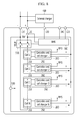
- FIG. 1 shows a block diagram of a battery pack according to an exemplary embodiment of the present invention.
- the battery pack 100 includes a plurality of cell modules 200 and a battery management system (BMS) 300.
- the battery pack 100 connects the cell modules 200 in series, parallel, or a combination of series and parallel, and the respective cell modules are connected to the battery management system 300.
- the battery pack 100 receives current from an external charger 400 to charge the battery cells, and it supplies the current to an external load (not shown) and is then discharged.
- the battery pack 100 further includes a switch 500 between the external charger 400 and the cell module 200, a cooling device 600 for cooling the battery pack 100, and a current sensor 700 for sensing the current flowing to the battery pack 100.
- the cell module 200 includes a battery cell 210, a controller 230, a cell charger 250, a temperature sensor 270, and a heating mat 280.
- the cell module 200 communicates with the battery management system 300 to transmit signals thereto and receive them therefrom.
- the cell module 200 receives power to drive the controller 230 and the cell charger 250, and in this instance, it can receive power from the external charger 400.
- the battery cell 210 is rechargeable.
- the battery cell 210 can be charged by current supplied from the external charger 400, and it can be individually charged by current appropriate for the state of the battery cell 210, supplied from the cell charger 250.
- the battery cell 210 can be charged in various ways, and for example, it can be charged by the constant current/constant voltage (CC/CV) method or a method designated by the battery management system 300.
- CC/CV constant current/constant voltage
- the controller 230 monitors the state of the battery cell 210 and periodically transmits the state information to the battery management system 300. In this instance, the controller 230 monitors voltage, current, and temperature of the battery cell 210. The controller 230 controls the cell charger 250 based on control signals transmitted by the battery management system 300. When receiving the control signal for charging the battery cell 210 from the battery management system 300, the controller 230 controls the cell charger 250 to charge the rest of the battery cell 210. In this instance, the controller 230 controls the cell charger 250 to fully charge the battery cell 210 depending on the state of the battery cell 210.
- the cell charger 250 charges the battery cell 210 by control of the controller 230.
- the cell charger 250 fully charges the battery cell 210 according to the state of the battery cell 210. In this instance, the cell charger 250 uses power supplied from the external charger 400 to charge the battery cell 210.
- the temperature sensor 270 and the heating mat 280 are used to operate the temperature of the battery cell 210 within a predetermined reference range.
- the temperature sensor 270 measures the temperature of the battery cell 210 and transmits it to the controller 230.
- the heating mat 280 is operated by the controller 230 and increases the temperature of the battery cell 210.
- the temperature sensor 270 may be a negative temperature coefficient (NTC) temperature sensor, a device having electrical resistance related to temperature.
- NTC negative temperature coefficient
- the battery management system 300 includes a cell module interface 310 communicating with the cell module 200, a manager 330, and an external interface 350.
- the cell module interface 310 communicates with the cell module 200 to receive state information of the battery cell 210 from the cell module 200, and transmits various control signals to the cell module 200.
- the manager 330 manages the cell module 200 and various connection devices, based on the information provided by the cell module interface 310.
- the manager 330 controls the switch 500 to control the current supplied by the external charger 400. For example, when one of a plurality of cell modules reaches a reference voltage which is a charging stop voltage, the manager 330 stops the current supply to a plurality of battery cells from the external charger 400. The manager 330 determines charging method of the cell module based on the state information of the cell module, the voltage and the current. And the manager 330 transmits a control signal for charging the rest individually, to the cell module.
- the manager 330 monitors the cell module 200 based on the information of the battery cell 210 transmitted from the cell module 200.
- the manager 330 transmits a control signal on charging to at least one of a plurality of cell modules.
- the manager 330 may operate the cooling device 600 to cool the battery pack 100.
- the manager 330 may transmit a control signal for operating the heating mat 280 to the corresponding cell module.
- the manager 330 knows that the battery pack 100 is overdischarged, overcharged, or out of an appropriate temperature through the current sensor 700. That is, the manager 330 controls the switch 500 to protect the battery pack 100 when the current flowing to the battery pack 100 from the external charger 400 or the current flowing to an external load (not shown) from the battery pack 100 digresses from the safety range.
- the manager 330 uses an identity number of the assembled cell modules to manage history of the respective cell modules.
- the manager 330 performs an aging process during the process for manufacturing the battery pack 100, evaluates the battery cell based on charging and discharging capacity of the battery cell, and determines bad battery cells that are below a predetermined standard.
- the manager 330 calculates a residual lifespan of the battery cell based on a change of available capacity of the battery cell in use, internal resistance, and a number of charges and discharges, and then displays a replacement indicator of a cell module of the lifespan-expired battery cell.
- the external interface 350 can communicate with an external device of the battery pack 100.
- the external interface 350 can include a TCP/IP port, a USB port, a controller area network (CAN) communication port, and an external memory connector.
- CAN controller area network
- the switch 500 is opened or closed based on control of the battery management system 300.
- the switch 500 is a power controllable element, and it can be an insulated gate bipolar transistor (IGBT) or a power field effect transistor (FET).
- IGBT insulated gate bipolar transistor
- FET power field effect transistor
- the switch 500 can be realized as a magnetic contactor (MC) type.
- the current sensor 700 can be a Hall sensor or a shunt resistor.
- FIG. 2 shows a block diagram of a cell module according to an exemplary embodiment of the present invention.
- the cell module 200 includes a battery cell 210, a controller 230, a cell charger 250, a temperature sensor 270, and a heating mat 280.
- the cell module 200 is connected to another battery cell or an external charger through a positive electrode connection terminal 290 and a negative electrode connection terminal 291.
- the cell module 200 further includes a communication connection terminal 294 for communicating with the battery management system 300, and a power connection terminal 295 to which power of the cell module 200 is connected.
- the battery cell 210 can be charged by receiving the current from the external charger 400 through the positive electrode connection terminal 290 and the negative electrode connection terminal 291, and it can also be charged individually by receiving a current that is appropriate for the state of the battery cell 210 from the cell charger 250.
- the controller 230 measures the voltage and the current charged of the battery cell 210, and monitors the temperature through the temperature sensor 270.
- the controller 230 periodically transmits the monitored state information to the battery management system 300.
- the controller 230 operates the heating mat 280 to increase the temperature of the battery cell 210 when the temperature of the battery cell 210 is less than the reference temperature.
- the controller 230 controls the cell charger 250 based on the control signal received from the battery management system 300.
- the controller 230 controls the cell charger 250 to charge the battery cell 210 to full capacity.
- the cell charger 250 charges the battery cell 210 according to control by the controller 230.
- the cell charger 250 fully charges the battery cell 210 according to the state of the battery cell 210. In this instance, the cell charger 250 charges the battery cell 210 by cell charging power.
- the cell charger 250 receives the cell charging power through the power connection terminal 295, and the cell charging power can be AC power or DC power.
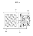
- FIG. 3 and FIG. 4 show a configuration diagram of a cell module according to an exemplary embodiment of the present invention.
- the cell module 200 includes a control board 292 on which the controller 230 and the cell charger 250 are realized, a battery cell 210, a temperature sensor 270, and a heating mat 280 provided above or below the battery cell 210, mounted in a cell tray 293.
- the cell tray 293 further includes a positive electrode connection terminal 290, a negative electrode connection terminal 291, a communication connection terminal 294, and a power connection terminal 295.
- the cell module 200 includes a control board 292 on which the controller 230 and the cell charger 250 are realized, a battery cell 210, a temperature sensor 270, and a heating mat 280 provided above or below the battery cell 210, mounted in a cell tray 293.
- FIG. 5 shows a perspective view of a battery pack according to an exemplary embodiment of the present invention.
- the battery pack 100 includes a plurality of cell modules 200 which can be connected in one of series, parallel, and a combination of series and parallel, and the stacked cell modules are respectively connected to the battery management system 300.
- the cell modules 200 can be stacked in various ways, and for example, as shown in FIG. 5 , they can be stacked by putting one cell module in one layer, or by stacking at least two cell modules in one layer.
- the battery cells are assembled into a pack to which various circuits are connected, so it is difficult to replace a bad battery cell.
- the battery pack 100 using cell modules 200 it is easy to replace a bad cell. So user can use the battery pack 100 for a long time by replaing bad cells.
- the battery pack 100 since the cell modules 200 are individually fully charged, the battery pack 100 does not need to undergo a cell balancing process for reducing the voltage of the battery pack by performing a balancing process with a battery cell with a low voltage. Therefore, the battery pack 100 is charged with the external charger 400, and it is fully charged up to the maximum charging voltage of the battery pack 100 without lowering the voltage, thereby increasing available capacity of the battery pack.
- FIG. 6 shows a schematic diagram of a power and control signal of a battery pack according to an exemplary embodiment of the present invention.
- the battery pack 100 charges and discharges the battery cells through a cell module stack 800 formed by stacking cell modules 200, and the battery management system 300.
- the battery management system 300 controls a current flow between the cell module stack 800 and the external charger 400 through switches 510 and 530.
- the switch 530 can be omitted depending on the circuit.
- the respective cell modules of the cell module stack 800 transmit voltage, current, and temperature information of the battery cells to the battery management system 300 (S520).
- the battery management system 300 transmits a control signal to the switch 510 so as to stop the current supplied to the battery cells from the external charger 400 (S530).
- the battery management system 300 can transmit a control signal to the external charger 400 before turning off the switch 510 so that the external charger 400 may reduce the supplied current (S540).
- the battery management system 300 transmits a control signal to the cell module stack 800 so as to individually charge the battery cells to full capacity based on the states of the cell modules (S550).
- the battery management system 300 can transmit the control signal so as to charge them according to the CC/CV method.
- the battery management system 300 turns on the switch 530 to supply power to the cell modules from the external charger 400 (S560).
- the cell modules can be connected in series, in parallel, or in a combination of series and parallel to receive power through the switch 530.
- FIG. 7 shows a schematic diagram of a power and control signal of a battery pack according to another exemplary embodiment of the present invention.
- the battery management system 300 monitors the current flowing to the external load 900 from the cell module stack 800 through the current sensor 700 (S620).
- the battery management system 300 transmits a control signal to the switch 510 to control the current (S630).
- the respective cell modules of the cell module stack 800 transmit the voltage, current, temperature information of the battery cells to the battery management system 300 (S640).
- the battery management system 300 analyzes the states of the cell modules based on the information transmitted by the cell module stack 800, and transmits a control signal to the cell module stack 800 (S650).
- FIG. 8 and FIG. 9 show a connection state of a battery pack according to an exemplary embodiment of the present invention.
- the battery pack 100 includes a plurality of terminals 110, 120, 130, 140, and 150 connected to an external device.
- the terminals 110 and 120 are input and output terminals of the battery pack 100, and are connected to the external charger 400 or an external load (not shown).
- the terminal 130 communicates with the external charger 400.
- the battery management system 300 can receive power from the outside through the terminal 140 or from cell module stack 800. Depending on the design, the battery management system 300 can receive power from an inner part of the battery pack 100.
- the battery management system 300 communicates with the external device and transmits and receives control signals thereto and therefrom through the terminal 150.
- the battery management system 300 communicates with various sorts of devices such as an external inverter through the terminal 150 to transmit and receive signals.
- the battery management system 300 transmits an operation state of the battery management system 300 and the states of the cell modules to the external device.
- the battery management system 300 can transmit a state of charge (SOC) and a state of health (SOH), battery-related information, to the external device connected to the terminal 150.
- SOC state of charge
- SOH state of health
- the current sensor 700 is provided on at least one line to which the terminals 110 and 120 and the cell module are connected.
- N N is a natural number
- cell modules 200 are connected, and the cell modules respectively include a battery cell 210 and a control board 292 on which the controller 230 and the cell charger 250 are realized.
- the N battery cells are coupled in series according to polarity, the negative electrode of the battery cells coupled in series are connected to the terminal 110 through the switch 510, and the positive electrode of the battery cells coupled in series are connected to the terminal 120 through the switch 510.
- the cell modules are coupled in parallel to the terminals 110 and 120 to receive power.
- the switch 530 can be provided between the cell module and the terminals (110/120).
- the cell module is connected to the battery management system 300.
- the cell charger 250 receives power to charge the battery cell 210, cell charging power of the module is AC power or DC power, DC power is supplied to the cell module through the switch 530, and the cell charger can fully charge the battery cell through AC power (not shown).
- the battery management system 300 is connected to and communicates with N cell modules 200, switches 510 and 530, a current sensor 700, and terminals 130,140, and 150.
- the battery pack 100 includes a plurality of terminals 110, 120, 130, 140, and 150 connected to an external device, a battery management system 300, and a current sensor 700.
- the N (N is a natural number) cell modules 200 are connected, and the cell modules respectively include a battery cell 210, a controller 230, and a cell charger 250.
- the N battery cells are coupled in series according to polarity, the negative electrode of the battery cells coupled in series are connected to the terminal 110 through the switch 510, and the positive electrode of the battery cells coupled in series are connected to the terminal 120 through the switch 510.
- the cell modules are coupled in series, one end of the cell modules coupled in series is connected to the terminal 110, and other end of the cell modules coupled in series is connected to the terminal 120 to receive power.
- the switch 530 can be provided between the cell module and the terminals (110/120).
- the cell module is connected to the battery management system 300.
- the battery management system 300 is connected to and communicates with N cell modules 200, switches 510 and 530, a current sensor 700, and terminals 130,140, and 150.
- FIG. 8 and FIG. 9 parallel and series connections are described, and the plurality of cell modules can be connected in a combination of series and parallel depending on the design.
- FIG. 10 shows a flowchart of a method for charging a battery pack according to an exemplary embodiment of the present invention.
- the battery management system 300 of the battery pack 100 charges a plurality of battery cells by the current supplied from the external charger 400 (S810). In this instance, the battery cells are charged simultaneously.
- the battery management system 300 turns on the switch 510 so that the current may be supplied to the battery cells from the external charger 400.
- the battery management system 300 can charge the battery cells through the CC/CV method.
- the battery management system 300 receives state information from the cell modules (S820).
- the state information includes voltage, current, and temperature information of the battery cell.
- the battery management system 300 determines whether one of a plurality of cell modules reaches a reference voltage (S830).
- the battery management system 300 controls the external charger 400 to reduce the supplied current (S840).
- the battery management system 300 can set a different amount of supplied current that is reduced depending on the maximum charging current of the cell module. Accordingly, the battery management system 300 prevents the voltage of the battery cell that is charged for the first time from being increased to be greater than the reference voltage, and thus protects the battery cell.
- the battery management system 300 turns off the switch 510 between the external charger 400 and a plurality of cell modules to stop the current supplied to the battery cells from the external charger 400 (S850). In another way, when there is a cell module reaching the reference voltage, the battery management system 300 can control the external charger 400 to reduce the supplied current or turn off the switch 510 to block the current supplied to the battery cells from the external charger 400.
- the battery management system 300 transmits a control signal to the cell modules so that the respective cell modules may individually charge the remaining capacity of the battery cell based on the state information transmitted by the cell modules (S860).
- the battery management system 300 analyzes voltage, current, and temperature information of the cell modules to determine a charging method that is appropriate for the cell module, and transmits a control signal to the corresponding cell module.
- the cell charger 250 individually charges the battery cell according to the control signal provided by the battery management system 300.
- the cell module monitors voltage, charging current, and temperature of the battery cell, and it is fully charged depending on the state of the battery cell. Therefore, the battery pack 100 does not need to undergo a cell balancing process for reducing the voltage of the battery pack by performing a balancing process with a low-voltage battery cell, and it is fully charged up to the maximum charging voltage of the battery pack 100 to thus increase the available capacity of the battery pack.
Landscapes
- Engineering & Computer Science (AREA)
- Chemical & Material Sciences (AREA)
- Chemical Kinetics & Catalysis (AREA)
- Electrochemistry (AREA)
- General Chemical & Material Sciences (AREA)
- Manufacturing & Machinery (AREA)
- Power Engineering (AREA)
- Microelectronics & Electronic Packaging (AREA)
- Secondary Cells (AREA)
- Physics & Mathematics (AREA)
- Automation & Control Theory (AREA)
- Life Sciences & Earth Sciences (AREA)
- Biophysics (AREA)
- General Physics & Mathematics (AREA)
- Charge And Discharge Circuits For Batteries Or The Like (AREA)
- Battery Mounting, Suspending (AREA)
Abstract
Description
- The present invention relates to a battery pack and a method for charging a battery pack.
- Electronic devices such as laptops or mobile phones and vehicles receive energy from batteries. Such batteries can be manufactured as a battery pack including battery cells and various circuits. Regarding the battery pack, the battery cells are charged by an external charger and the battery pack is repeatedly discharged to supply voltage and current to external loads such as electronic devices or vehicles.
- In the conventional battery packs, the battery cells are coupled in series and are charged by using an external charger. In this instance, the cells may fail to be uniformly charged or discharged and charging deviation or discharging deviation may occur. The battery pack performs a cell balancing process so as to correct the deviation, which takes much time and increases the time for charging the battery pack.
- The above information disclosed in this Background section is only for enhancement of understanding of the background of the invention and therefore it may contain information that does not form the prior art that is already known in this country to a person of ordinary skill in the art.
- The present invention has been made in an effort to provide a battery pack for monitoring and controlling cell modules by using a battery management system, quickly charging the battery pack with predetermined energy by using an external charger, and charging each battery cell by using a cell charger of the cell module to thereby fully charge them quickly without deviation between the cells, and a method for charging a battery pack.
- An exemplary embodiment of the present invention provides a battery pack including: a plurality of cell modules including a plurality of battery cells; and a battery management system for transmitting a control signal on charging to at least one of the plurality of cell modules based on state information of a battery cell transmitted by the cell modules, and controlling a current supplied to the cell modules by an external charger based on the state information, wherein the cell modules are charged to a predetermined capacity of the battery cell in connection with the external charger, and are charged to full capacity of the battery cell according to the control signal.
- The cell module further includes a controller for monitoring a state of the battery cell, transmitting monitored state information to the battery management system, and receiving the control signal, and a cell charger for charging the battery cell by control of the controller.
- The controller monitors voltage, current, and temperature of the battery cell.
- The battery pack further includes a switch located between one end of the battery cells coupled in series according to polarity and one end of the external charger, wherein the battery management system controls turn-on/off of the switch.
- When one of the plurality of cell modules reaches a reference voltage, the battery management system controls the switch based on the state information to stop a current supplied to the battery cells by the external charger.
- When the current supplied to the battery cells by the external charger is stopped, the battery management system analyzes states of the cell modules based on the state information, and transmits a control signal to the cell modules so as to be individually charged to full capacity from the external charger.
- The battery management system sets a normal operational range of the cell modules based on at least one of the voltage, the current, and the temperature, and when at least one of the cell modules fails to satisfy the normal operational range based on the state information, the battery management system controls the switch to stop the current supplied to the battery cells by the external charger.
- The battery management system manages the state information provided by the cell modules, and checks performance of the cell modules to determine a replacement.
- The state information includes temperature information, and the battery management system compares temperatures of the cell modules with a reference temperature based on the state information, and transmits a control signal for operating a heating mat to the cell module having a temperature that is less than the reference temperature, and operates a cooling device when there is a cell module with a temperature that is greater than the reference temperature.
- Another embodiment of the present invention provides a method for a battery management system of a battery pack to charge a plurality of cell modules including a plurality of battery cells, including: charging the battery cells by using current supplied by an external charger; monitoring states of the cell modules and determining whether one of the cell modules reaches a reference voltage; stopping the charging process when there is a cell module reaching the reference voltage; and analyzing state information of the cell modules and transmitting control signals to the cell modules so that the cell modules may be individually charged to full capacity of the battery cell.
- The determining is performed based on voltage information of the battery cells provided by the cell modules.
- The stopping includes reducing a current supply by controlling the external charger, and stopping the current supplied to the battery cells by the external charger by controlling a switch between the external charger and the cell modules.
- According to the embodiments of the present invention, the battery pack is manufactured by connecting cell modules including a battery cell and a cell charger so each cell module can be replaced, and it is easy to replace a bad cell of the battery pack. Further, the battery management system and the cell module monitor states of the cell modules and transmit and receive information with each other, and the cell module charges the individual battery cells by using the cell charger included in the cell module rather than by using the external charger. Therefore, there is no need to perform cell balancing for reducing inter-cell deviation occurring when externally charging or discharging, and the battery pack is fully charged within a short time.
-
-
FIG. 1 shows a block diagram of a battery pack according to an exemplary embodiment of the present invention. -
FIG. 2 shows a block diagram of a cell module according to an exemplary embodiment of the present invention. -
FIG. 3 andFIG. 4 show a configuration diagram of a cell module according to an exemplary embodiment of the present invention. -
FIG. 5 shows a perspective view of a battery pack according to an exemplary embodiment of the present invention. -
FIG. 6 shows a schematic diagram of a power and control signal of a battery pack according to an exemplary embodiment of the present invention. -
FIG. 7 shows a schematic diagram of a power and control signal of a battery pack according to another exemplary embodiment of the present invention. -
FIG. 8 andFIG. 9 show a connection state of a battery pack according to an exemplary embodiment of the present invention. -
FIG. 10 shows a flowchart of a method for charging a battery pack according to an exemplary embodiment of the present invention. - In the following detailed description, only certain exemplary embodiments have been shown and described, simply by way of illustration. As those skilled in the art would realize, the described embodiments may be modified in various different ways, all without departing from the spirit or scope of the inventive concept. Accordingly, the drawings and description are to be regarded as illustrative in nature and not restrictive. Like reference numerals designate like elements throughout the specification.
- Throughout the specification, unless explicitly described to the contrary, the word "comprise" and variations such as "comprises" or "comprising" will be understood to imply the inclusion of stated elements but not the exclusion of any other elements.
- A battery pack and a method for charging a battery pack according to exemplary embodiments will now be described with reference to accompanying drawings.
-
FIG. 1 shows a block diagram of a battery pack according to an exemplary embodiment of the present invention. - Referring to
FIG. 1 , thebattery pack 100 includes a plurality ofcell modules 200 and a battery management system (BMS) 300. Thebattery pack 100 connects thecell modules 200 in series, parallel, or a combination of series and parallel, and the respective cell modules are connected to thebattery management system 300. Thebattery pack 100 receives current from anexternal charger 400 to charge the battery cells, and it supplies the current to an external load (not shown) and is then discharged. Thebattery pack 100 further includes aswitch 500 between theexternal charger 400 and thecell module 200, acooling device 600 for cooling thebattery pack 100, and acurrent sensor 700 for sensing the current flowing to thebattery pack 100. - The
cell module 200 includes abattery cell 210, acontroller 230, acell charger 250, atemperature sensor 270, and aheating mat 280. Thecell module 200 communicates with thebattery management system 300 to transmit signals thereto and receive them therefrom. Thecell module 200 receives power to drive thecontroller 230 and thecell charger 250, and in this instance, it can receive power from theexternal charger 400. - The
battery cell 210 is rechargeable. Thebattery cell 210 can be charged by current supplied from theexternal charger 400, and it can be individually charged by current appropriate for the state of thebattery cell 210, supplied from thecell charger 250. Thebattery cell 210 can be charged in various ways, and for example, it can be charged by the constant current/constant voltage (CC/CV) method or a method designated by thebattery management system 300. - The
controller 230 monitors the state of thebattery cell 210 and periodically transmits the state information to thebattery management system 300. In this instance, thecontroller 230 monitors voltage, current, and temperature of thebattery cell 210. Thecontroller 230 controls thecell charger 250 based on control signals transmitted by thebattery management system 300. When receiving the control signal for charging thebattery cell 210 from thebattery management system 300, thecontroller 230 controls thecell charger 250 to charge the rest of thebattery cell 210. In this instance, thecontroller 230 controls thecell charger 250 to fully charge thebattery cell 210 depending on the state of thebattery cell 210. - The
cell charger 250 charges thebattery cell 210 by control of thecontroller 230. Thecell charger 250 fully charges thebattery cell 210 according to the state of thebattery cell 210. In this instance, thecell charger 250 uses power supplied from theexternal charger 400 to charge thebattery cell 210. - The
temperature sensor 270 and theheating mat 280 are used to operate the temperature of thebattery cell 210 within a predetermined reference range. Thetemperature sensor 270 measures the temperature of thebattery cell 210 and transmits it to thecontroller 230. Theheating mat 280 is operated by thecontroller 230 and increases the temperature of thebattery cell 210. In this instance, thetemperature sensor 270 may be a negative temperature coefficient (NTC) temperature sensor, a device having electrical resistance related to temperature. - The
battery management system 300 includes acell module interface 310 communicating with thecell module 200, amanager 330, and anexternal interface 350. - The
cell module interface 310 communicates with thecell module 200 to receive state information of thebattery cell 210 from thecell module 200, and transmits various control signals to thecell module 200. - The
manager 330 manages thecell module 200 and various connection devices, based on the information provided by thecell module interface 310. - The
manager 330 controls theswitch 500 to control the current supplied by theexternal charger 400. For example, when one of a plurality of cell modules reaches a reference voltage which is a charging stop voltage, themanager 330 stops the current supply to a plurality of battery cells from theexternal charger 400. Themanager 330 determines charging method of the cell module based on the state information of the cell module, the voltage and the current. And themanager 330 transmits a control signal for charging the rest individually, to the cell module. - The
manager 330 monitors thecell module 200 based on the information of thebattery cell 210 transmitted from thecell module 200. Themanager 330 transmits a control signal on charging to at least one of a plurality of cell modules. In this instance, when the temperature of thebattery cell 210 is greater than a reference temperature, themanager 330 may operate thecooling device 600 to cool thebattery pack 100. When the temperature of thebattery cell 210 is less than the reference temperature, themanager 330 may transmit a control signal for operating theheating mat 280 to the corresponding cell module. - The
manager 330 knows that thebattery pack 100 is overdischarged, overcharged, or out of an appropriate temperature through thecurrent sensor 700. That is, themanager 330 controls theswitch 500 to protect thebattery pack 100 when the current flowing to thebattery pack 100 from theexternal charger 400 or the current flowing to an external load (not shown) from thebattery pack 100 digresses from the safety range. - Also, the
manager 330 uses an identity number of the assembled cell modules to manage history of the respective cell modules. Themanager 330 performs an aging process during the process for manufacturing thebattery pack 100, evaluates the battery cell based on charging and discharging capacity of the battery cell, and determines bad battery cells that are below a predetermined standard. Themanager 330 calculates a residual lifespan of the battery cell based on a change of available capacity of the battery cell in use, internal resistance, and a number of charges and discharges, and then displays a replacement indicator of a cell module of the lifespan-expired battery cell. - The
external interface 350 can communicate with an external device of thebattery pack 100. For example, theexternal interface 350 can include a TCP/IP port, a USB port, a controller area network (CAN) communication port, and an external memory connector. - The
switch 500 is opened or closed based on control of thebattery management system 300. Theswitch 500 is a power controllable element, and it can be an insulated gate bipolar transistor (IGBT) or a power field effect transistor (FET). Theswitch 500 can be realized as a magnetic contactor (MC) type. - The
current sensor 700 can be a Hall sensor or a shunt resistor. -
FIG. 2 shows a block diagram of a cell module according to an exemplary embodiment of the present invention. - Referring to
FIG. 2 , thecell module 200 includes abattery cell 210, acontroller 230, acell charger 250, atemperature sensor 270, and aheating mat 280. Thecell module 200 is connected to another battery cell or an external charger through a positiveelectrode connection terminal 290 and a negativeelectrode connection terminal 291. Thecell module 200 further includes acommunication connection terminal 294 for communicating with thebattery management system 300, and apower connection terminal 295 to which power of thecell module 200 is connected. Thebattery cell 210 can be charged by receiving the current from theexternal charger 400 through the positiveelectrode connection terminal 290 and the negativeelectrode connection terminal 291, and it can also be charged individually by receiving a current that is appropriate for the state of thebattery cell 210 from thecell charger 250. - The
controller 230 measures the voltage and the current charged of thebattery cell 210, and monitors the temperature through thetemperature sensor 270. Thecontroller 230 periodically transmits the monitored state information to thebattery management system 300. In this instance, thecontroller 230 operates theheating mat 280 to increase the temperature of thebattery cell 210 when the temperature of thebattery cell 210 is less than the reference temperature. Thecontroller 230 controls thecell charger 250 based on the control signal received from thebattery management system 300. When receiving the control signal for charging thebattery cell 210 from thebattery management system 300, thecontroller 230 controls thecell charger 250 to charge thebattery cell 210 to full capacity. - The
cell charger 250 charges thebattery cell 210 according to control by thecontroller 230. Thecell charger 250 fully charges thebattery cell 210 according to the state of thebattery cell 210. In this instance, thecell charger 250 charges thebattery cell 210 by cell charging power. Thecell charger 250 receives the cell charging power through thepower connection terminal 295, and the cell charging power can be AC power or DC power. -
FIG. 3 andFIG. 4 show a configuration diagram of a cell module according to an exemplary embodiment of the present invention. - Referring to
FIG. 3 , thecell module 200 includes acontrol board 292 on which thecontroller 230 and thecell charger 250 are realized, abattery cell 210, atemperature sensor 270, and aheating mat 280 provided above or below thebattery cell 210, mounted in acell tray 293. Thecell tray 293 further includes a positiveelectrode connection terminal 290, a negativeelectrode connection terminal 291, acommunication connection terminal 294, and apower connection terminal 295. - Referring to
FIG. 4 , thecell module 200 includes acontrol board 292 on which thecontroller 230 and thecell charger 250 are realized, abattery cell 210, atemperature sensor 270, and aheating mat 280 provided above or below thebattery cell 210, mounted in acell tray 293. -
FIG. 5 shows a perspective view of a battery pack according to an exemplary embodiment of the present invention. - Referring to
FIG. 5 , thebattery pack 100 includes a plurality ofcell modules 200 which can be connected in one of series, parallel, and a combination of series and parallel, and the stacked cell modules are respectively connected to thebattery management system 300. Thecell modules 200 can be stacked in various ways, and for example, as shown inFIG. 5 , they can be stacked by putting one cell module in one layer, or by stacking at least two cell modules in one layer. - When the prior art battery pack is manufactured, the battery cells are assembled into a pack to which various circuits are connected, so it is difficult to replace a bad battery cell. However, regarding the
battery pack 100 usingcell modules 200, it is easy to replace a bad cell. So user can use thebattery pack 100 for a long time by replaing bad cells. Also, since thecell modules 200 are individually fully charged, thebattery pack 100 does not need to undergo a cell balancing process for reducing the voltage of the battery pack by performing a balancing process with a battery cell with a low voltage. Therefore, thebattery pack 100 is charged with theexternal charger 400, and it is fully charged up to the maximum charging voltage of thebattery pack 100 without lowering the voltage, thereby increasing available capacity of the battery pack. -
FIG. 6 shows a schematic diagram of a power and control signal of a battery pack according to an exemplary embodiment of the present invention. - Referring to
FIG. 6 , thebattery pack 100 charges and discharges the battery cells through acell module stack 800 formed by stackingcell modules 200, and thebattery management system 300. Thebattery management system 300 controls a current flow between thecell module stack 800 and theexternal charger 400 throughswitches switch 530 can be omitted depending on the circuit. - When the
external charger 400 is connected to thebattery pack 100, a current is supplied to thecell module stack 800 from the external charger 400 (S510). - The respective cell modules of the
cell module stack 800 transmit voltage, current, and temperature information of the battery cells to the battery management system 300 (S520). - When one of a plurality of cell modules reaches a reference voltage, the
battery management system 300 transmits a control signal to theswitch 510 so as to stop the current supplied to the battery cells from the external charger 400 (S530). - In another way, the
battery management system 300 can transmit a control signal to theexternal charger 400 before turning off theswitch 510 so that theexternal charger 400 may reduce the supplied current (S540). - The
battery management system 300 transmits a control signal to thecell module stack 800 so as to individually charge the battery cells to full capacity based on the states of the cell modules (S550). Thebattery management system 300 can transmit the control signal so as to charge them according to the CC/CV method. - In this instance, the
battery management system 300 turns on theswitch 530 to supply power to the cell modules from the external charger 400 (S560). The cell modules can be connected in series, in parallel, or in a combination of series and parallel to receive power through theswitch 530. -
FIG. 7 shows a schematic diagram of a power and control signal of a battery pack according to another exemplary embodiment of the present invention. - Referring to
FIG. 7 , when anexternal load 900 is connected to thebattery pack 100, the current flows to theexternal load 900 from the cell module stack 800 (S61 0). - The
battery management system 300 monitors the current flowing to theexternal load 900 from thecell module stack 800 through the current sensor 700 (S620). - When the current sensed by the
current sensor 700 digresses from the safety range, thebattery management system 300 transmits a control signal to theswitch 510 to control the current (S630). - The respective cell modules of the
cell module stack 800 transmit the voltage, current, temperature information of the battery cells to the battery management system 300 (S640). - The
battery management system 300 analyzes the states of the cell modules based on the information transmitted by thecell module stack 800, and transmits a control signal to the cell module stack 800 (S650). -
FIG. 8 andFIG. 9 show a connection state of a battery pack according to an exemplary embodiment of the present invention. - Referring to
FIG. 8 , thebattery pack 100 includes a plurality ofterminals - The
terminals battery pack 100, and are connected to theexternal charger 400 or an external load (not shown). - The terminal 130 communicates with the
external charger 400. - The
battery management system 300 can receive power from the outside through the terminal 140 or fromcell module stack 800. Depending on the design, thebattery management system 300 can receive power from an inner part of thebattery pack 100. - The
battery management system 300 communicates with the external device and transmits and receives control signals thereto and therefrom through the terminal 150. Thebattery management system 300 communicates with various sorts of devices such as an external inverter through the terminal 150 to transmit and receive signals. Also, thebattery management system 300 transmits an operation state of thebattery management system 300 and the states of the cell modules to the external device. For example, thebattery management system 300 can transmit a state of charge (SOC) and a state of health (SOH), battery-related information, to the external device connected to the terminal 150. - The
current sensor 700 is provided on at least one line to which theterminals - N (N is a natural number)
cell modules 200 are connected, and the cell modules respectively include abattery cell 210 and acontrol board 292 on which thecontroller 230 and thecell charger 250 are realized. The N battery cells are coupled in series according to polarity, the negative electrode of the battery cells coupled in series are connected to the terminal 110 through theswitch 510, and the positive electrode of the battery cells coupled in series are connected to the terminal 120 through theswitch 510. Further, the cell modules are coupled in parallel to theterminals switch 530 can be provided between the cell module and the terminals (110/120). The cell module is connected to thebattery management system 300. Thecell charger 250 receives power to charge thebattery cell 210, cell charging power of the module is AC power or DC power, DC power is supplied to the cell module through theswitch 530, and the cell charger can fully charge the battery cell through AC power (not shown). - The
battery management system 300 is connected to and communicates withN cell modules 200,switches current sensor 700, and terminals 130,140, and 150. - Referring to
FIG. 9 , thebattery pack 100 includes a plurality ofterminals battery management system 300, and acurrent sensor 700. - The N (N is a natural number)
cell modules 200 are connected, and the cell modules respectively include abattery cell 210, acontroller 230, and acell charger 250. The N battery cells are coupled in series according to polarity, the negative electrode of the battery cells coupled in series are connected to the terminal 110 through theswitch 510, and the positive electrode of the battery cells coupled in series are connected to the terminal 120 through theswitch 510. Also, the cell modules are coupled in series, one end of the cell modules coupled in series is connected to the terminal 110, and other end of the cell modules coupled in series is connected to the terminal 120 to receive power. Theswitch 530 can be provided between the cell module and the terminals (110/120). The cell module is connected to thebattery management system 300. - The
battery management system 300 is connected to and communicates withN cell modules 200,switches current sensor 700, and terminals 130,140, and 150. - In
FIG. 8 andFIG. 9 , parallel and series connections are described, and the plurality of cell modules can be connected in a combination of series and parallel depending on the design. -
FIG. 10 shows a flowchart of a method for charging a battery pack according to an exemplary embodiment of the present invention. - Referring to
FIG. 10 , thebattery management system 300 of thebattery pack 100 charges a plurality of battery cells by the current supplied from the external charger 400 (S810). In this instance, the battery cells are charged simultaneously. Thebattery management system 300 turns on theswitch 510 so that the current may be supplied to the battery cells from theexternal charger 400. Thebattery management system 300 can charge the battery cells through the CC/CV method. - The
battery management system 300 receives state information from the cell modules (S820). The state information includes voltage, current, and temperature information of the battery cell. - The
battery management system 300 determines whether one of a plurality of cell modules reaches a reference voltage (S830). - When there is a cell module reaching the reference voltage, the
battery management system 300 controls theexternal charger 400 to reduce the supplied current (S840). Thebattery management system 300 can set a different amount of supplied current that is reduced depending on the maximum charging current of the cell module. Accordingly, thebattery management system 300 prevents the voltage of the battery cell that is charged for the first time from being increased to be greater than the reference voltage, and thus protects the battery cell. - The
battery management system 300 turns off theswitch 510 between theexternal charger 400 and a plurality of cell modules to stop the current supplied to the battery cells from the external charger 400 (S850). In another way, when there is a cell module reaching the reference voltage, thebattery management system 300 can control theexternal charger 400 to reduce the supplied current or turn off theswitch 510 to block the current supplied to the battery cells from theexternal charger 400. - The
battery management system 300 transmits a control signal to the cell modules so that the respective cell modules may individually charge the remaining capacity of the battery cell based on the state information transmitted by the cell modules (S860). Thebattery management system 300 analyzes voltage, current, and temperature information of the cell modules to determine a charging method that is appropriate for the cell module, and transmits a control signal to the corresponding cell module. - The
cell charger 250 individually charges the battery cell according to the control signal provided by thebattery management system 300. In this instance, the cell module monitors voltage, charging current, and temperature of the battery cell, and it is fully charged depending on the state of the battery cell. Therefore, thebattery pack 100 does not need to undergo a cell balancing process for reducing the voltage of the battery pack by performing a balancing process with a low-voltage battery cell, and it is fully charged up to the maximum charging voltage of thebattery pack 100 to thus increase the available capacity of the battery pack. - While this invention has been described in connection with what is presently considered to be practical exemplary embodiments, it is to be understood that the invention is not limited to the disclosed embodiments, but, on the contrary, is intended to cover various modifications and equivalent arrangements included within the spirit and scope of the appended claims.
Claims (12)
- A battery pack comprising:a plurality of cell modules including a plurality of battery cells; anda battery management system for transmitting a control signal on charging to at least one of the plurality of cell modules based on state information of a battery cell transmitted by the cell modules, and controlling a current supplied to the cell modules by an external charger based on the state information, whereinthe cell modules are charged to a predetermined capacity of the battery cell in connection with the external charger, and are charged to full capacity of the battery cell individually according to the control signal.
- The battery pack of claim 1, wherein
the cell module further comprises
a controller for monitoring a state of the battery cell, transmitting monitored state information to the battery management system, and receiving the control signal, and
a cell charger for charging the battery cell by control of the controller. - The battery pack of claim 2, wherein
the controller monitors voltage, current, and temperature of the battery cell. - The battery pack of claim 1, further comprising
a switch located between one end of the battery cells coupled in series according to polarity and one end of the external charger, wherein
the battery management system controls turn-on/off of the switch. - The battery pack of claim 4, wherein
when one of the plurality of cell modules reaches a reference voltage, the battery management system controls the switch based on the state information to stop a current supplied to the battery cells by the external charger. - The battery pack of claim 5, wherein
when the current supplied to the battery cells by the external charger is stopped, the battery management system analyzes states of the cell modules based on the state information and transmits a control signal to the cell modules so as to be individually charged to full capacity. - The battery pack of claim 4, wherein
the battery management system sets a normal operational range of the cell modules based on at least one of the voltage, the current, and the temperature, and when at least one of the cell modules fails to satisfy the normal operational range based on the state information, the battery management system controls the switch to stop the current supplied to the battery cells by the external charger. - The battery pack of claim 1, wherein
the battery management system manages the state information provided by the cell modules, and checks performance of the cell modules to determine a replacement. - The battery pack of claim 1, wherein
the state information includes temperature information, and
the battery management system compares temperatures of the cell modules with a reference temperature based on the state information, and transmits a control signal for operating a heating mat to the cell module having a temperature that is less than the reference temperature, and operates a cooling device when there is a cell module with a temperature that is greater than the reference temperature. - A method for a battery management system of a battery pack to charge a plurality of cell modules including a plurality of battery cell, comprising:charging the battery cells by using current supplied by an external charger;monitoring states of the cell modules and determining whether one of the cell modules reaches a reference voltage;stopping the charging process when there is a cell module reaching the reference voltage; andanalyzing state information of the cell modules and transmitting control signals to the cell modules so that the respective cell modules may be individually charged to full capacity of the battery cell.
- The method of claim 10, wherein
the determining is performed based on voltage information of the battery cells provided by the cell modules. - The method of claim 10, wherein
the stopping comprises:reducing a current supply by controlling the external charger; andstopping the current supplied to the battery cells by the external charger by controlling a switch between the external charger and the cell modules.
Applications Claiming Priority (3)
| Application Number | Priority Date | Filing Date | Title |
|---|---|---|---|
| KR20100052510 | 2010-06-03 | ||
| KR1020110048711A KR101184752B1 (en) | 2010-06-03 | 2011-05-23 | Battery package and charging method of battery package |
| PCT/KR2011/003953 WO2011152639A2 (en) | 2010-06-03 | 2011-05-30 | Battery pack and method for charging battery pack |
Publications (2)
| Publication Number | Publication Date |
|---|---|
| EP2579382A2 true EP2579382A2 (en) | 2013-04-10 |
| EP2579382A4 EP2579382A4 (en) | 2014-02-26 |
Family
ID=45500805
Family Applications (1)
| Application Number | Title | Priority Date | Filing Date |
|---|---|---|---|
| EP11789997.1A Withdrawn EP2579382A4 (en) | 2010-06-03 | 2011-05-30 | BATTERY PACK AND METHOD FOR BATTERY PACK CHARGING |
Country Status (6)
| Country | Link |
|---|---|
| US (1) | US20130069594A1 (en) |
| EP (1) | EP2579382A4 (en) |
| JP (2) | JP5951595B2 (en) |
| KR (1) | KR101184752B1 (en) |
| CN (1) | CN102859784B (en) |
| WO (1) | WO2011152639A2 (en) |
Cited By (4)
| Publication number | Priority date | Publication date | Assignee | Title |
|---|---|---|---|---|
| EP2978044A1 (en) * | 2014-07-24 | 2016-01-27 | The Boeing Company | Battery pack including stacked battery-board assemblies |
| WO2018095726A1 (en) * | 2016-11-24 | 2018-05-31 | Robert Bosch Gmbh | System and method for storing a battery |
| EP3576213A4 (en) * | 2017-01-24 | 2020-06-24 | Samsung SDI Co., Ltd. | BATTERY PACK, METHOD FOR CONTROLLING THE CHARGE OF THE BATTERY PACK, AND VEHICLE COMPRISING THE BATTERY PACK |
| WO2021003731A1 (en) * | 2019-07-11 | 2021-01-14 | 3Dom Inc. | Battery system, battery management method |
Families Citing this family (66)
| Publication number | Priority date | Publication date | Assignee | Title |
|---|---|---|---|---|
| JP2013123344A (en) * | 2011-12-12 | 2013-06-20 | Toyota Industries Corp | Device for equalizing battery cell voltages |
| KR101289610B1 (en) * | 2011-12-27 | 2013-07-24 | 넥스콘 테크놀러지 주식회사 | Management Systembattery Of Battery pack |
| KR102040063B1 (en) * | 2012-06-05 | 2019-11-06 | 에스케이이노베이션 주식회사 | Energy storage system and method |
| US9502910B2 (en) * | 2013-03-15 | 2016-11-22 | Samsung Electro-Mechanics Co., Ltd. | Power charging apparatus and battery apparatus |
| KR101462338B1 (en) | 2013-04-15 | 2014-11-20 | 숭실대학교산학협력단 | AC-connected power conversion circuit |
| JP6196466B2 (en) * | 2013-05-10 | 2017-09-13 | Fdk株式会社 | Power supply |
| CN106463983A (en) * | 2014-03-24 | 2017-02-22 | 郑润珥 | Battery packs, cell modules, and cell module assemblies |
| CN104348219B (en) * | 2014-07-15 | 2017-02-08 | 常州格力博有限公司 | Electrical system with replaceable batteries |
| KR102318789B1 (en) * | 2014-09-02 | 2021-10-28 | 삼성전자 주식회사 | Method for managing bettery charging and electlronic device implementing the same |
| KR102316600B1 (en) * | 2014-10-14 | 2021-10-25 | 현대모비스 주식회사 | Power supply aparatus for electric vehicle and power supply method using it |
| KR101772975B1 (en) | 2015-05-18 | 2017-08-30 | 주식회사 루비 | Battery module with cell balancing function and Battery System having that battery module |
| US11258104B2 (en) * | 2015-06-30 | 2022-02-22 | Faraday & Future Inc. | Vehicle energy-storage systems |
| WO2017014444A1 (en) * | 2015-07-22 | 2017-01-26 | 주식회사 루비 | Battery pack, battery charger, and battery charger system |
| TWI610486B (en) * | 2015-10-14 | 2018-01-01 | 低碳動能開發股份有限公司 | Active balance charging device |
| KR102205315B1 (en) * | 2015-10-28 | 2021-01-20 | 주식회사 엘지화학 | Programmable battery management system |
| JP6649834B2 (en) * | 2016-03-31 | 2020-02-19 | 株式会社マキタ | Inspection device for battery pack for power tool |
| US11533953B2 (en) | 2016-06-29 | 2022-12-27 | Philip Morris Products S.A. | Battery powered aerosol-generating device comprising a temperature dependent battery pre-heating |
| JP6520848B2 (en) * | 2016-07-04 | 2019-05-29 | トヨタ自動車株式会社 | Battery charging system for electric vehicles |
| CN106129321B (en) * | 2016-08-18 | 2018-12-04 | 系统电子科技(镇江)有限公司 | The battery modules of improvement |
| KR101751236B1 (en) | 2016-12-13 | 2017-06-27 | 장원석 | Battery charging system for electric vehicle using separated multi-layer and method thereof |
| KR102053880B1 (en) * | 2017-06-27 | 2020-01-22 | 디와이 주식회사 | Electronic Vehicle controlling SoC and DOD |
| EP3422527B1 (en) * | 2017-06-27 | 2022-07-06 | EH Europe GmbH | Battery apparatus |
| CN109435777B (en) * | 2017-08-31 | 2021-02-23 | 比亚迪股份有限公司 | Battery equalization system, vehicle, battery equalization method, and storage medium |
| US20190081372A1 (en) * | 2017-09-12 | 2019-03-14 | Sf Motors, Inc. | Modular battery system to provide power to electric vehicles |
| CN107656211A (en) * | 2017-09-15 | 2018-02-02 | 武汉中航传感技术有限责任公司 | Batteries monitoring system |
| KR102030118B1 (en) * | 2017-11-03 | 2019-10-08 | 주식회사 엘지화학 | Apparatus for managing battery, battery pack including the same and vehicle including the same |
| KR102000113B1 (en) * | 2017-12-28 | 2019-07-17 | 한국에너지기술연구원 | Apparatus and system for storing battery, and method for managing battery |
| US10367358B2 (en) | 2018-01-03 | 2019-07-30 | Fu-Chieh Chen | Active equalizing charging device |
| KR101871410B1 (en) * | 2018-04-02 | 2018-06-28 | 유용선 | Modular power supply system |
| CN108448180B (en) * | 2018-04-10 | 2024-01-30 | 中国船舶重工集团公司第七0四研究所 | Ship battery management system |
| KR102606004B1 (en) * | 2018-07-26 | 2023-11-27 | 삼성전자주식회사 | Electronic device and the method for Managing Battery thereof |
| CN112514194A (en) * | 2018-08-08 | 2021-03-16 | 罗伯特·博世有限公司 | Method and device for monitoring an electrical energy store |
| KR102645676B1 (en) * | 2018-12-10 | 2024-03-11 | 삼성전자주식회사 | Electronic device and method for adjusting charge cycle or discharge cycle of battery |
| JP6955624B2 (en) * | 2018-12-21 | 2021-10-27 | オッポ広東移動通信有限公司Guangdong Oppo Mobile Telecommunications Corp., Ltd. | Multiple cell charging methods, devices and electronics |
| KR102147889B1 (en) * | 2018-12-28 | 2020-08-25 | 엔에이치네트웍스 주식회사 | Backup Power Supply ESS System For Communication Devices Applying IoT Module And Lithium Battery Pack Module |
| KR102676149B1 (en) | 2019-01-21 | 2024-06-17 | 주식회사 엘지에너지솔루션 | Battery Manager System, Electronic Control Unit, and Communication method between Battery Manager System and Electronic Control Unit |
| KR102710752B1 (en) * | 2019-01-31 | 2024-09-27 | 삼성전자주식회사 | Method to control charging of multiple batteries and electronic device applying the method |
| USD953268S1 (en) | 2019-09-05 | 2022-05-31 | Techtronic Cordless Gp | Electrical interface |
| USD929335S1 (en) | 2019-09-05 | 2021-08-31 | Techtronic Cordless Gp | Electrical interface |
| USD929339S1 (en) | 2019-09-05 | 2021-08-31 | Techtronic Cordless Gp | Electrical interface |
| USD1012855S1 (en) | 2019-09-05 | 2024-01-30 | Techtronic Cordless Gp | Battery pack |
| USD929336S1 (en) | 2019-09-05 | 2021-08-31 | Techtronic Cordless Gp | Electrical interface |
| USD929334S1 (en) | 2019-09-05 | 2021-08-31 | Techtronic Cordless Gp | Electrical interface |
| USD929338S1 (en) | 2019-09-05 | 2021-08-31 | Techtronic Cordless Gp | Electrical interface |
| USD929337S1 (en) | 2019-09-05 | 2021-08-31 | Techtronic Cordless Gp | Electrical interface |
| KR102196351B1 (en) * | 2019-11-01 | 2020-12-29 | 주식회사 티팩토리 | battery protection unit using embedded module and protection circuit mocdule |
| WO2021095895A1 (en) * | 2019-11-11 | 2021-05-20 | 엘지전자 주식회사 | Electronic device and charging control method of electronic device |
| KR102246451B1 (en) * | 2019-11-11 | 2021-04-30 | 주식회사 에스제이 테크 | Module battery system |
| JP7603699B2 (en) | 2020-01-31 | 2024-12-20 | ウィスク アエロ エルエルシー | Aircraft equipped with tilting fan assemblies |
| CN115298092A (en) | 2020-02-10 | 2022-11-04 | 威斯克航空有限责任公司 | Aircraft with propeller |
| US20210362849A1 (en) | 2020-05-19 | 2021-11-25 | Archer Aviation, Inc. | Vertical take-off and landing aircraft |
| KR102467169B1 (en) * | 2020-10-20 | 2022-11-15 | (주)와이파워원 | Apparatus and system for multiple wireless battery-charging and charging-control method |
| KR20220057368A (en) * | 2020-10-29 | 2022-05-09 | 주식회사 엘지에너지솔루션 | Apparatus and method for managing battery, battery managing system |
| KR20220100332A (en) * | 2021-01-08 | 2022-07-15 | 주식회사 엘지에너지솔루션 | Battery apparatus and method of supplying voltage |
| TWI795749B (en) * | 2021-03-24 | 2023-03-11 | 邑達電子股份有限公司 | Battery pack and serial structure of battery packs |
| EP4086980A1 (en) * | 2021-05-03 | 2022-11-09 | Napptilus Battery Labs, S.L. | Hybrid nanogel electrodes and cell stacking in distributed architectures for high power electrical energy hybrid storage systems |
| CN113471604A (en) * | 2021-06-29 | 2021-10-01 | 东风海博新能源科技有限公司 | A power battery pack |
| ES2997560T3 (en) * | 2021-08-31 | 2025-02-17 | Contemporary Amperex Technology Hong Kong Ltd | Method for managing charging in a battery swapping station, battery swapping cabinet and system |
| KR102734170B1 (en) * | 2021-10-18 | 2024-11-25 | 일호솔루션 주식회사 | Multi-output energy storage system |
| KR102482959B1 (en) * | 2022-05-27 | 2022-12-29 | 김지혜 | Fast charger for electric vehicle batteries including superconducting battery tray |
| CN115224759A (en) * | 2022-07-08 | 2022-10-21 | 太普动力新能源(常熟)股份有限公司 | Intelligent charging system |
| EP4536552A1 (en) | 2022-10-07 | 2025-04-16 | Archer Aviation, Inc. | Systems and methods for motor cooling in vtol aircraft |
| US11613350B1 (en) | 2022-10-07 | 2023-03-28 | Archer Aviation, Inc. | Systems and methods for lifter motor cooling in eVTOL aircraft |
| WO2024097148A1 (en) * | 2022-11-04 | 2024-05-10 | REON Technology, Inc. | Battery management system with controlled replacement |
| CN121219933A (en) * | 2024-03-19 | 2025-12-26 | Tvs电机股份有限公司 | Systems and methods for charging battery packs |
| CN119209827A (en) * | 2024-09-30 | 2024-12-27 | 河池市宜州区凯文立电池能源有限公司 | A lithium battery equalization system and equalization method thereof |
Family Cites Families (18)
| Publication number | Priority date | Publication date | Assignee | Title |
|---|---|---|---|---|
| JPH08317572A (en) * | 1995-05-15 | 1996-11-29 | Nippondenso Co Ltd | Battery pack charge state control device |
| CA2225585A1 (en) * | 1997-12-12 | 1999-06-12 | Hydro-Quebec | Battery control system |
| JP2000184615A (en) | 1998-12-18 | 2000-06-30 | Matsushita Electric Ind Co Ltd | Battery management device and battery pack used for backup power supply |
| JP3405526B2 (en) * | 1999-04-02 | 2003-05-12 | エヌイーシートーキン栃木株式会社 | Multiple battery pack power supply |
| FR2800212B1 (en) * | 1999-10-21 | 2007-09-14 | Cit Alcatel | CHARGING MANAGEMENT SYSTEM FOR BATTERY OF ELECTRIC BATTERIES AND IN PARTICULAR A BATTERY COMPRISING LITHIUM CELLS |
| KR100610845B1 (en) | 1999-12-30 | 2006-08-09 | 현대자동차주식회사 | How to troubleshoot battery thermostat of electric vehicle |
| JP2003157908A (en) * | 2001-09-10 | 2003-05-30 | Ntt Power & Building Facilities Inc | Lithium ion secondary battery charging apparatus and method |
| KR100459440B1 (en) | 2002-11-29 | 2004-12-03 | 엘지전자 주식회사 | Battery and charging and power supply method thereof |
| KR100686794B1 (en) | 2005-01-25 | 2007-02-23 | 삼성에스디아이 주식회사 | Battery pack monitoring device and method |
| CN2907033Y (en) * | 2006-04-05 | 2007-05-30 | 上海云骅电子科技有限公司 | Charging device with battery capacity recovery function |
| KR100946019B1 (en) * | 2006-04-24 | 2010-03-09 | 미쓰비시덴키 가부시키가이샤 | Power storage devices |
| JP2008067486A (en) * | 2006-09-07 | 2008-03-21 | Shin Kobe Electric Mach Co Ltd | Charging method |
| JP4313809B2 (en) * | 2006-09-14 | 2009-08-12 | 株式会社Nttファシリティーズ | Rechargeable battery pack system and battery pack charge control method |
| US8228040B2 (en) * | 2006-11-06 | 2012-07-24 | Nec Corporation | Electric cells for battery pack, battery control system, and battery control method |
| WO2008137764A1 (en) * | 2007-05-03 | 2008-11-13 | Sendyne Corporation | Fine-controlled battery-charging system |
| WO2008151659A2 (en) * | 2007-06-11 | 2008-12-18 | Abb Research Ltd | System and method for equalizing state of charge in a battery system |
| US7880434B2 (en) * | 2008-05-21 | 2011-02-01 | Southwest Electronic Energy Corporation | System for balancing a plurality of battery pack system modules connected in series |
| JP5453769B2 (en) * | 2008-11-06 | 2014-03-26 | トヨタ自動車株式会社 | Vehicle battery diagnosis system and vehicle battery diagnosis method |
-
2011
- 2011-05-23 KR KR1020110048711A patent/KR101184752B1/en active Active
- 2011-05-30 JP JP2013501203A patent/JP5951595B2/en active Active
- 2011-05-30 US US13/701,382 patent/US20130069594A1/en not_active Abandoned
- 2011-05-30 WO PCT/KR2011/003953 patent/WO2011152639A2/en not_active Ceased
- 2011-05-30 EP EP11789997.1A patent/EP2579382A4/en not_active Withdrawn
- 2011-05-30 CN CN201180021037.7A patent/CN102859784B/en active Active
-
2015
- 2015-05-01 JP JP2015094106A patent/JP2015181335A/en active Pending
Cited By (10)
| Publication number | Priority date | Publication date | Assignee | Title |
|---|---|---|---|---|
| EP2978044A1 (en) * | 2014-07-24 | 2016-01-27 | The Boeing Company | Battery pack including stacked battery-board assemblies |
| RU2691098C2 (en) * | 2014-07-24 | 2019-06-11 | Зе Боинг Компани | Unit of storage batteries, containing stacks of assemblies made on the basis of boards and accumulator batteries |
| US10826136B2 (en) | 2014-07-24 | 2020-11-03 | The Boeing Company | Battery pack including stacked battery-board assemblies |
| WO2018095726A1 (en) * | 2016-11-24 | 2018-05-31 | Robert Bosch Gmbh | System and method for storing a battery |
| US11362374B2 (en) | 2016-11-24 | 2022-06-14 | Robert Bosch Gmbh | System and method for storing a battery |
| EP3576213A4 (en) * | 2017-01-24 | 2020-06-24 | Samsung SDI Co., Ltd. | BATTERY PACK, METHOD FOR CONTROLLING THE CHARGE OF THE BATTERY PACK, AND VEHICLE COMPRISING THE BATTERY PACK |
| US11322946B2 (en) | 2017-01-24 | 2022-05-03 | Samsung Sdi Co., Ltd. | Battery pack, method for controlling charging of battery pack, and vehicle comprising battery pack |
| WO2021003731A1 (en) * | 2019-07-11 | 2021-01-14 | 3Dom Inc. | Battery system, battery management method |
| CN114270593A (en) * | 2019-07-11 | 2022-04-01 | 上达股份有限公司 | Battery system and battery management method |
| CN114270593B (en) * | 2019-07-11 | 2023-01-06 | 上达联盟有限公司 | Battery system, battery management method |
Also Published As
| Publication number | Publication date |
|---|---|
| CN102859784A (en) | 2013-01-02 |
| JP5951595B2 (en) | 2016-07-13 |
| WO2011152639A3 (en) | 2012-05-03 |
| EP2579382A4 (en) | 2014-02-26 |
| KR20110132977A (en) | 2011-12-09 |
| US20130069594A1 (en) | 2013-03-21 |
| KR101184752B1 (en) | 2012-09-20 |
| CN102859784B (en) | 2016-08-03 |
| JP2015181335A (en) | 2015-10-15 |
| WO2011152639A2 (en) | 2011-12-08 |
| JP2013524745A (en) | 2013-06-17 |
Similar Documents
| Publication | Publication Date | Title |
|---|---|---|
| CN102859784B (en) | Set of cells and the method being used for charging for set of cells | |
| KR101249972B1 (en) | Battery pack and active cell balancing method of battery pack | |
| US10277064B2 (en) | Power tool and control method thereof | |
| RU2526854C2 (en) | Improved system of accumulator batteries | |
| CN102326313B (en) | Charging control circuit, battery pack, and charging system | |
| US8531160B2 (en) | Rechargeable battery management | |
| US10141551B2 (en) | Battery system | |
| CN103891093B (en) | Monitoring device of battery system and power storage device having same | |
| US20090295335A1 (en) | Battery pack and charging method for the same | |
| KR20170071949A (en) | Battery Pack and Battery System Including The Same | |
| KR102177495B1 (en) | Device for parallel connected battery pack individual controls | |
| KR20150107032A (en) | Battery pack | |
| US20170117723A1 (en) | Battery fleet charging system | |
| US20140103877A1 (en) | Battery management system | |
| US12308687B2 (en) | Battery charge/discharge control device and battery management device | |
| US9172260B2 (en) | Efficient battery management system | |
| AU2017101729A4 (en) | Power tool and control method thereof | |
| CN115800422B (en) | Energy storage system and method for regulating an energy storage system | |
| RU2743789C1 (en) | Balancer of voltages of electric energy accumulators and a method of charge voltage alignment on series connected n electric energy accumulators | |
| CN211556939U (en) | Balance protection circuit for battery pack | |
| KR100574037B1 (en) | Individual battery charger | |
| CN113078720A (en) | Charging and discharging circuit and method | |
| EP4568056A1 (en) | Battery pack group and driving method thereof | |
| KR200359024Y1 (en) | Battery charger capable of individual charging | |
| KR102931488B1 (en) | Method for detecting defective battery cell and battery management system providing the same |
Legal Events
| Date | Code | Title | Description |
|---|---|---|---|
| PUAI | Public reference made under article 153(3) epc to a published international application that has entered the european phase |
Free format text: ORIGINAL CODE: 0009012 |
|
| 17P | Request for examination filed |
Effective date: 20121130 |
|
| AK | Designated contracting states |
Kind code of ref document: A2 Designated state(s): AL AT BE BG CH CY CZ DE DK EE ES FI FR GB GR HR HU IE IS IT LI LT LU LV MC MK MT NL NO PL PT RO RS SE SI SK SM TR |
|
| DAX | Request for extension of the european patent (deleted) | ||
| A4 | Supplementary search report drawn up and despatched |
Effective date: 20140127 |
|
| RIC1 | Information provided on ipc code assigned before grant |
Ipc: H01M 10/48 20060101ALI20140129BHEP Ipc: H01M 10/44 20060101AFI20140129BHEP Ipc: H01M 10/60 20140101ALI20140129BHEP Ipc: G01R 31/36 20060101ALI20140129BHEP Ipc: H02J 7/00 20060101ALI20140129BHEP |
|
| STAA | Information on the status of an ep patent application or granted ep patent |
Free format text: STATUS: THE APPLICATION IS DEEMED TO BE WITHDRAWN |
|
| 18D | Application deemed to be withdrawn |
Effective date: 20151201 |