EP2579213A2 - Apparatus, method, program and recording medium for image processing - Google Patents
Apparatus, method, program and recording medium for image processing Download PDFInfo
- Publication number
- EP2579213A2 EP2579213A2 EP12187292.3A EP12187292A EP2579213A2 EP 2579213 A2 EP2579213 A2 EP 2579213A2 EP 12187292 A EP12187292 A EP 12187292A EP 2579213 A2 EP2579213 A2 EP 2579213A2
- Authority
- EP
- European Patent Office
- Prior art keywords
- image
- output area
- image sensor
- information
- frame
- Prior art date
- Legal status (The legal status is an assumption and is not a legal conclusion. Google has not performed a legal analysis and makes no representation as to the accuracy of the status listed.)
- Granted
Links
Images







Classifications
-
- G—PHYSICS
- G06—COMPUTING OR CALCULATING; COUNTING
- G06T—IMAGE DATA PROCESSING OR GENERATION, IN GENERAL
- G06T5/00—Image enhancement or restoration
- G06T5/73—Deblurring; Sharpening
-
- G—PHYSICS
- G06—COMPUTING OR CALCULATING; COUNTING
- G06T—IMAGE DATA PROCESSING OR GENERATION, IN GENERAL
- G06T5/00—Image enhancement or restoration
- G06T5/50—Image enhancement or restoration using two or more images, e.g. averaging or subtraction
-
- G—PHYSICS
- G06—COMPUTING OR CALCULATING; COUNTING
- G06T—IMAGE DATA PROCESSING OR GENERATION, IN GENERAL
- G06T7/00—Image analysis
- G06T7/20—Analysis of motion
- G06T7/246—Analysis of motion using feature-based methods, e.g. the tracking of corners or segments
- G06T7/248—Analysis of motion using feature-based methods, e.g. the tracking of corners or segments involving reference images or patches
-
- H—ELECTRICITY
- H04—ELECTRIC COMMUNICATION TECHNIQUE
- H04N—PICTORIAL COMMUNICATION, e.g. TELEVISION
- H04N23/00—Cameras or camera modules comprising electronic image sensors; Control thereof
- H04N23/60—Control of cameras or camera modules
- H04N23/68—Control of cameras or camera modules for stable pick-up of the scene, e.g. compensating for camera body vibrations
- H04N23/681—Motion detection
- H04N23/6811—Motion detection based on the image signal
-
- H—ELECTRICITY
- H04—ELECTRIC COMMUNICATION TECHNIQUE
- H04N—PICTORIAL COMMUNICATION, e.g. TELEVISION
- H04N23/00—Cameras or camera modules comprising electronic image sensors; Control thereof
- H04N23/60—Control of cameras or camera modules
- H04N23/68—Control of cameras or camera modules for stable pick-up of the scene, e.g. compensating for camera body vibrations
- H04N23/682—Vibration or motion blur correction
- H04N23/684—Vibration or motion blur correction performed by controlling the image sensor readout, e.g. by controlling the integration time
- H04N23/6842—Vibration or motion blur correction performed by controlling the image sensor readout, e.g. by controlling the integration time by controlling the scanning position, e.g. windowing
-
- G—PHYSICS
- G06—COMPUTING OR CALCULATING; COUNTING
- G06T—IMAGE DATA PROCESSING OR GENERATION, IN GENERAL
- G06T2207/00—Indexing scheme for image analysis or image enhancement
- G06T2207/10—Image acquisition modality
- G06T2207/10004—Still image; Photographic image
- G06T2207/10012—Stereo images
-
- G—PHYSICS
- G06—COMPUTING OR CALCULATING; COUNTING
- G06T—IMAGE DATA PROCESSING OR GENERATION, IN GENERAL
- G06T2207/00—Indexing scheme for image analysis or image enhancement
- G06T2207/10—Image acquisition modality
- G06T2207/10016—Video; Image sequence
- G06T2207/10021—Stereoscopic video; Stereoscopic image sequence
-
- G—PHYSICS
- G06—COMPUTING OR CALCULATING; COUNTING
- G06T—IMAGE DATA PROCESSING OR GENERATION, IN GENERAL
- G06T2207/00—Indexing scheme for image analysis or image enhancement
- G06T2207/20—Special algorithmic details
- G06T2207/20021—Dividing image into blocks, subimages or windows
-
- G—PHYSICS
- G06—COMPUTING OR CALCULATING; COUNTING
- G06T—IMAGE DATA PROCESSING OR GENERATION, IN GENERAL
- G06T2207/00—Indexing scheme for image analysis or image enhancement
- G06T2207/20—Special algorithmic details
- G06T2207/20172—Image enhancement details
- G06T2207/20201—Motion blur correction
Definitions
- the present invention relates to an apparatus, a method, a program and a recording medium for image processing.
- Patent Document 1 an apparatus which calculates movement data between a base image and a reference image, calculates a pixel value difference between images in respective matching blocks based on the movement data, determines a superposing ratio between the base image and the reference image in every block based on the pixel value difference, and performs superposing processing to obtain a composite image, and thereby sharper and hand shake-corrected images are provided.
- Patent Document 1 Japanese Patent Laid-Open No. 2009-164857
- a technology for combining images taken by a plurality of cameras so as to provide a three-dimensional image with a depth.
- a technology is also known which provides a three-dimensional moving image by generating and displaying such a three-dimensional image in succession.
- correction processing such as hand shake correction and distortion correction.
- An image processing apparatus which performs image processing of a plurality of frame images generated by an imaging device having a plurality of image sensors each continuously generating a first frame image and a second frame image in sequence, comprising: a placement information acquisition section which acquires, for each image sensor, placement information indicating placement conditions of the image sensors with respect to the imaging device; a movement information acquisition section which acquires movement information of the imaging device between the first frame image and the second frame image; and an output area acquisition section which acquires, for each image sensor, position information of a second output area within the second frame image, the second output area corresponding to a first output area within the first frame image, wherein the output area acquisition section acquires: as a reference base, the second output area of a base image sensor among the plurality of image sensors based on the position information of the first output area determined by the placement information and based on the movement information; and the second output area of an image sensor being different from the base image sensor, among the plurality of image sensors based on the placement
- An image processing method for performing image processing of a plurality of frame images generated by an imaging device having a plurality of image sensors which continuously generate a first frame image and a second frame image in sequence, comprising: a placement information acquisition step of acquiring, for every image sensor, placement information indicating placement conditions of the image sensors with respect to the imaging device; a movement information acquisition step of acquiring movement information of the imaging device between the first frame image and the second frame image; and an output area acquisition step of acquiring, for every image sensor, position information of a second output area within the second frame image which corresponds to a first output area within the first frame image, wherein in the output area acquisition step, as a reference base, the second output area of a base image sensor among the plurality of image sensors is acquired based on position information of the first output area determined by the placement information and based on the movement information, and the second output area of an image sensor being different from the base image sensor, among the plurality of image sensors is acquired based on placement information of the base image
- An image processing program is an image processing program for operating a computer to perform image processing of a plurality of frame images generated by an imaging device having a plurality of image sensors which continuously generate a first frame image and a second frame image in sequence, the program causing the computer to function as:
- the second output area of the base image sensor is acquired based on position information of the first output area determined by the placement information and based on the movement information, and the second output area of an image sensor being different from the base image sensor, among the plurality of image sensors is acquired based on placement information of the base image sensor, placement information of the other image sensor, and the movement information.
- the second output area of the base image sensor and the second output area of the other image sensor are acquired based on the movement information which is common between these image sensors. Accordingly, correction processing can be performed with consistency among the images obtained from the plurality of image sensors.
- the apparatus may include a determination section which determines for all the image sensors whether or not the position information of the second output area is positioned within the second frame image, wherein when the position information of the second output area is not positioned within the second frame image, the output area acquisition section sets moving amount obtained by a difference between the position information of the first output area and the position information of the second output area to be smaller until the position information of the second output area is positioned within the second frame image in all the image sensors.
- a determination section which determines for all the image sensors whether or not the position information of the second output area is positioned within the second frame image, wherein when the position information of the second output area is not positioned within the second frame image, the output area acquisition section sets moving amount obtained by a difference between the position information of the first output area and the position information of the second output area to be smaller until the position information of the second output area is positioned within the second frame image in all the image sensors.
- the movement information acquisition section may acquire the movement information from the first frame image and the second frame image generated by the base image sensor. In this case, since the movement information can be obtained from images, the movement information which is common among the plurality of image sensors can be acquired without adding a new hardware configuration.
- the movement information acquisition section may acquire the movement information by a gyro sensor.
- the movement information common among the plurality of image sensors can be acquired by the gyro sensor, and thereby a processing load can be reduced.
- the movement information acquisition section may acquire as the movement information a weighted average of the movement information acquired from the first frame image and the second frame image generated by the plurality of image sensors.
- the movement information is acquired based on the plurality of image sensors, and thereby the movement information can be acquired with sufficient accuracy.
- the base image sensor may be selected from the plurality of image sensors based on image pickup conditions. In this case, by selecting, for example, an image sensor having sufficient performance as the base image sensor, the movement information can be acquired with sufficient accuracy.
- the output area acquisition section may use an area other than an output area being needed because of using the plurality of image sensors as an area for use in correction with movement.
- a margin for obtaining a three-dimensional image can also be used for correction with movement, and thereby a plurality of correction processes can be performed with one margin. Accordingly, it becomes possible to reduce decrease in the number of valid pixels after correction processing, which is caused by the necessity of securing the margin.
- An image processing apparatus of a first embodiment is an apparatus which performs hand shake correction processing being consistent among images inputted from the plurality of image sensors.
- the image processing apparatus is mounted on mobile phones, digital cameras, video cameras, or general computer systems. In one example, the apparatus is used for multiple cameras. In the present embodiment, a description is given of a configuration including two image sensors as an example of the plurality of image sensors.
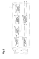
- FIG. 1 shows input frames generated by two image sensors, a first image sensor and a second image sensor, and output frames obtained by clipping a part of a pixel area of the input frames.
- first output areas the areas clipped from a first frame and a second frame and generated by the first image sensor (first output areas) are respectively referred to as a first output area A11 and a second output area A12.
- second output areas the areas clipped from a first frame and a second frame and generated by the second image sensor (second output areas) are also respectively referred to as a first output area A21 and a second output area A22.
- a specified image area which includes an object T is clipped as the first output area A11 from the first frame image generated by the first image sensor, and the first output area A21 corresponding to the first output area A11 is clipped from the first frame image generated by the second image sensor 12.
- a three-dimensional image is obtained from disparity information between the first output area A11 and the first output area A21.
- the position of the first output area A21 corresponding to the first output area A11 is uniquely determined by placement information, such as a placement position and a placement angle of the second image sensor with respect to the first image sensor.
- the position of the first output area A11 corresponding to the first output area A21 is uniquely determined by placement information, such as a placement position and a placement angle of the first image sensor with respect to the second image sensor. The placement information will be described later in detail.
- the image processing apparatus detects movement information of an imaging section 10 between the first frame image and the second frame image. Corresponding to moving amount of the imaging section, the image processing apparatus moves the position of the second output area A12 of the first image sensor and the position of the second output area A22 of the second image sensor, and acquires position information of the moved second output areas A12 and A22. In this case, if hand shake correction is independently performed on each of the image sensors, it is difficult to associate the second output area A12 with the second output area A22, which may result in failure of acquiring appropriate disparity information.
- moving amount of the output area obtained based on the movement information of one image sensor is reflected upon the output area of the other image sensor so as to implement consistent hand shake correction regardless of the placement information.
- FIG. 2 is a block diagram showing a functional configuration of an image processing apparatus 1 in the present embodiment.
- the image processing apparatus 1 is an apparatus which performs image processing of images generated by the imaging section 10 having the plurality of image sensors.
- the imaging section 10 of the present embodiment includes two image sensors.
- the imaging section 10 includes a first image sensor 11 and a second image sensor 12.
- the first image sensor 11 and the second image sensor 12 are means for generating an image of a subject.
- the imaging section 10 comprises image sensors such as C-MOSs (Complementary Metal Oxide Semiconductors) and CCDs (Charged Coupled Devices) as its principal parts.
- the first image sensor 11 and the second image sensor 12 continuously generate a first frame image and a second frame image in sequence.
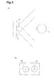
- the first image sensor 11 and the second image sensor 12 are placed at a specified interval and at a specified angle with each other as shown in FIGS. 3(a) and 3(b) .
- the imaging section 10 placed in this way generates an identical image pickup object T as shown in FIG. 3(a) .
- the imaging section 10 is composed of a base image sensor which serves as a reference base, among the plurality of image sensors and a reference image sensor which is an image sensor different from the base image sensor.
- the image generated by the base image sensor is used at the time of generating movement information for use in performing correction processing of an image.
- the first image sensor 11 is used as a base image sensor while the second image sensor 12 is used as a reference image sensor.
- the first image sensor 11 and the second image sensor 12 output generated first frame image and second frame image as image data to the image processing apparatus 1.
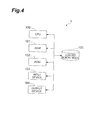
- FIG. 4 is a view showing a hardware configuration of the image processing apparatus 1.
- the image processing apparatus 1 is physically configured as a general computer system including a CPU (Central Processing Unit) 100, a main memory device such as a ROM (Read Only Memory) 101 and a RAM (Random Access Memory) 102, an input device 103 such as a keyboard, an output device 104 such as a display, and an auxiliary memory device 105 such as a hard disk.
- a CPU Central Processing Unit
- main memory device such as a ROM (Read Only Memory) 101 and a RAM (Random Access Memory) 102
- an input device 103 such as a keyboard
- an output device 104 such as a display
- an auxiliary memory device 105 such as a hard disk.
- the image processing apparatus 1 may include a communication module and the like.
- the image processing apparatus 1 includes a first input section 21, a second input section 22, a movement information acquisition section 30, a placement information acquisition section 40, a placement information storage section 41, and an output area acquisition section 50 as shown in FIG. 2 .
- the first input section 21 represents a function of acquiring image data (hereinafter also referred to as a base image) generated by the first image sensor 11 that is a base image sensor.
- the first input section 21 outputs a first frame image and a second frame image generated by the first image sensor to the movement information acquisition section 30 and to the output area acquisition section 50.
- the second input section 22 represents a function of acquiring image data (hereinafter also referred to as a reference image) generated by the second image sensor 12 that is a reference image sensor.
- the second input section 22 acquires each of a first frame image and a second frame image generated by the second image sensor 12.
- the second input section 22 outputs the first frame image and the second frame image generated by the second image sensor to the output area acquisition section 50.
- the movement information acquisition section 30 represents a function of acquiring movement information of the imaging section 10 between the first frame image and the second frame image.
- the movement information is a value calculated based on spatial displacement amount between the first frame image, used as reference, and the second frame image.
- the first frame image and the second frame image are divided into blocks of a specified size, and image signal patterns in respective blocks are searched to find the patterns which are most closely matched between the frames.
- Spatial displacement amount (motion vector) between the most closely matched image signal patterns between the frames is calculated as movement information. More specifically, as shown in FIG.
- the movement information acquisition section 30 acquires rotation amount ⁇ of the second frame image with respect to the first frame image, shift amount of an image origin dx, dy, and magnified amount s as the movement information.
- the movement information acquisition section 30 outputs the acquired movement information to the output area acquisition section 50.
- the placement information acquisition section 40 acquires placement information indicating placement conditions of the first image sensor 11 and the second image sensor 12 with respect to the imaging section 10.
- the placement information refers to parameters representing a placement position, a placement angle and the like of the image sensors with respect to the imaging section 10. These parameters are set at the time of designing the imaging section 10.
- the placement information acquisition section 40 acquires the placement information of the first image sensor 11 and the second image sensor 12 from the placement information storage section 41.
- the placement information acquisition section 40 outputs the acquired placement information of the first image sensor 11 and the second image sensor 12 to the output area acquisition section 50.
- the placement information acquisition section 40 may acquire the placement information directly from the imaging section 10.
- the output area acquisition section 50 acquires position information of the second output areas A12 and A22 within the second frame image, which correspond to first output areas A11 and A21 within the first frame image.
- the second output areas A12 and A22 corresponding to the first output areas A11 and A21 herein refer to the second output areas A12 and A22 which are the matches for the first output areas A11 and A21.
- the output area acquisition section 50 sets the positions of the second output areas A12 and A22 of the second frame image so that the second output areas A12 and A22 are not displaced from the first output areas A11 and A21 within the first frame image.
- the set positions of the second output areas A12 and A22 may be identical to the positions of the first output areas A11 and A21 or may be different from the positions of the first output areas A11 and A21.
- the output area acquisition section 50 acquires the second output area for each image sensor. Hereinafter, a description will be given of calculation processing for acquiring the position information of the second output area A12 of the first image sensor 11 and the second output area A22 of the second image sensor 12.
- FIG. 6 shows procedures in calculation processing for acquiring the position information of the second output area A12 of the first image sensor 11 and the second output area A22 of the second image sensor 12.
- the calculation processing of the output area acquisition section 50 will be described along with FIG. 6 .
- the output area acquisition section 50 converts an arbitrary coordinate (x', y') within the first frame image of the reference image into a coordinate (xn, yn) of a normal coordinate system by Formula (1).
- a normalized matrix is a matrix for converting the coordinate system of an inputted image to a normal coordinate system.
- a normalized-matrix M' -1 in Formula (1) is an inverse matrix of a denormalized matrix M' of the second image sensor 12 shown in Formula (2).
- the denormalized matrix M' is a matrix for converting the normal coordinate system to the coordinate system of the reference image.
- the denormalized matrix M' is obtained from clipping positions (x 1 ', y 1 '), (x 2 ', y 2 '), and (x 3 ', y 3 ') of the first output area A21 of the first frame image by the second image sensor 12.
- the denormalized matrix M' is determined by position information of the second image sensor 12 with respect to the imaging section 10 outputted from the placement information acquisition section 40.
- the output area acquisition section 50 converts the coordinate (xn, yn) of the normal coordinate system into a coordinate (x, y) in a coordinate system of the first image sensor I by Formula (3).
- a denormalized matrix M in Formula (3) is a matrix for converting the normal matrix into a coordinate system of the base image.
- the denormalized matrix M is shown in Formula (4).
- the denormalized matrix M is obtained from clipping positions (x 1 , y 1 ), (x 2 , y 2 ), and (x 3 , y 3 ) of the first output area A11 of the first frame image by the first image sensor 11.
- the denormalized matrix M is determined by position information of the first image sensor 11 with respect to the imaging section 10 outputted from the placement information acquisition section 40.
- the output area acquisition section 50 calculates a movement correction matrix C shown in Formula (5) based on the movement information acquired from the movement information acquisition section 30.
- the output area acquisition section 50 multiplies the coordinate (x, y) in the coordinate system of the first image sensor 11 by the movement correction matrix C to obtain a corrected coordinate (xc, yc) of the first image sensor 11.
- Moving amount and a moving direction from the coordinate (x, y) to the coordinate (xc, yc) are equivalent to moving amount and a moving direction of the second output area A12 with respect to the first output area A11.
- the output area acquisition section 50 acquires position information of the second output area A12 corresponding to the first output area A11.
- x ⁇ c ⁇ y ⁇ c ⁇ 1 M ⁇ M - 1 ⁇ CMM ⁇ - 1 x ⁇ ⁇ y ⁇ ⁇ 1
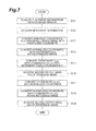
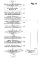
- the placement information acquisition section 40 acquires placement information of the first image sensor 11 and the second image sensor 12 from the placement information storage section 41 (S11).
- the movement information acquisition section 30 acquires movement information from a first frame image and a second frame image of the base image from the first input section 21 (S12).
- the output area acquisition section 50 converts an arbitrary coordinate (x', y') in the reference image into a normal coordinate (xn, yn) by Formula (1) (S13).
- the output area acquisition section 50 converts the normal coordinate (xn, yn) into a coordinate (x, y) within the base image by Formula (3) (S14).
- a denormalized matrix M for use in conversion to the coordinate (x, y) of the base image is a value determined by the placement information of the first image sensor 11 with respect to the imaging section 10.
- the output area acquisition section 50 converts, as shown in Formula (6), the coordinate (x, y) into a coordinate (xc, yc) with the movement correction matrix C determined by the movement information, which was acquired by the movement information acquisition section 30 (S15).
- the output area acquisition section 50 acquires position information of the second output area A12 from moving amount of the coordinate (xc, yc) with respect to the coordinate (x, y) (S16).
- the output area acquisition section 50 converts the coordinate (xc, yc) into a normal coordinate (xcn, ycn) by Formula (7) (S17).
- the output area acquisition section 50 converts the normal coordinate (xcn, ycn) into a coordinate (x'c, y'c) within the reference image by Formula (8) (S18).
- the output area acquisition section 50 acquires position information of the second output area A22 from moving amount of the coordinate (x'c, y'c) with respect to the coordinate (x', y') (S19). Once the position information of the second output area A12 is acquired, the image processing apparatus ends the image processing of FIG. 7 .
- the image processing program includes a main module, an input module, a movement information acquisition module, a placement information acquisition module, a placement information storage module, and an output area acquisition module.
- the main module is a portion which performs comprehensive control on image processing.
- the input module operates the computer so that inputted images are acquired from the first image sensor 11 and the second image sensor 12.
- Functions implemented by executing the movement information acquisition module, the placement information acquisition module, the placement information storage module, and the output area acquisition module are each similar to the functions of the movement information acquisition section 30, the placement information acquisition section 40, the placement information storage section 41, and the output area acquisition section 50.
- the image processing program is provided in the form of, for example, a storage medium such as ROMs or a semiconductor memory.
- the image processing program may also be provided via a network as data signals.
- the second output area A12 of the first image sensor 11 that is a base image sensor is acquired based on the position information of the first output area A11 determined by the placement information and based on the movement information
- the second output area A22 of the second image sensor 12 which is an image sensor different from the base image sensor, among the plurality of image sensors is acquired based on the placement information of the first image sensor 11, the placement information of the second image sensor 12, and the movement information. Since the second output area A12 of the first image sensor 11 and the second output area A22 of the second image sensor 12 are acquired based on the movement information which is common between the first image sensor 11 and the second image sensor 12, it becomes possible to perform correction processing consistent between the images obtained from the first image sensor 11 and the second image sensor 12. Moreover, since a margin for use in obtaining a three-dimensional image is used as a margin for use in hand shake correction, it becomes possible to provide an output image which was hand shake corrected without narrowing an output area.
- the image processing apparatus is different from that of the first embodiment in the following point. That is, when the position information of the second output areas A12 and A22 is not positioned within the second frame image, moving amount, which is obtained by a difference between the position information of the first output areas A11, A21 and the position information of the second output areas A12, A22, is adjusted to be small until the position information of the second output area is positioned within the second frame image in all the image sensors.
- FIG. 8 is a block diagram showing a functional configuration of an image processing apparatus 1A according to the present embodiment.
- the image processing apparatus 1A according to the present embodiment includes an output area acquisition section 50A in place of the output area acquisition section 50.
- the determination section 60 is provided in addition to the image processing apparatus 1 according to the first embodiment.
- Other structural components are the same as those of the first embodiment.
- the determination section 60 has the function to determine whether or not the second output areas A12 and A22 in the second frames of the first and second imaging devices are positioned respectively within the second frame images.
- the determination section 60 determines whether or not the coordinates of four apexes (xc1, yc1), (xc2, yc2), (xc3, yc3), and (xc4, yc4) of the second output area A12 calculated by Formula (6) are within the second frame image of the first image sensor 11.
- the determination section 60 also determines whether or not the coordinates of four apexes (x'c1, y'c1) (x'c2, y'c2), (x'c3, y'c3) and (x'c4, y'c4) of the second output area A22 calculated by Formula (9) are within the second frame image generated by the second image sensor 12. When it is determined that the coordinate of at least one of four apexes is not within the second frame image in either one of the second output area A12 or the second output area A22, the determination section 60 outputs a deviation signal, indicating that the second output areas A12 and A22 are out of the second frame image, to the output area acquisition section 50A.
- the output area acquisition section 50A Upon reception of the deviation signal from the determination section 60, the output area acquisition section 50A sets moving amount, which is obtained by a difference between the position information of the first output areas A11, A21 and the position information of the second output areas A12, A22, to be smaller until the position information of the second output areas A12, A22 is positioned within the second frame image in all the image sensors.
- moving amount which is obtained by a difference between the position information of the first output areas A11, A21 and the position information of the second output areas A12, A22, to be smaller until the position information of the second output areas A12, A22 is positioned within the second frame image in all the image sensors.
- FIG. 9(a) shows an example in which the second output area A12 is positioned out of the second frame of the first image sensor 11.
- a coordinate C (x3, y3) and a coordinate C (x4, y4) of the second output area A12 are positioned out of the second frame.
- the output area acquisition section 50A calculates a frame inside/outside ratio r.
- a frame inside/outside ratio r of the coordinate C (x3, y3) is calculated.
- a frame inside/outside ratio r of the coordinate C (x4, y4) may be calculated instead.
- the frame inside/outside ratio r is defined as a ratio between a length of a portion of the straight line inside the second frame and a length of a portion of the straight line outside the second frame.
- the output area acquisition section 50A calculates the frame inside/outside ratio r, and then updates the correction matrix C by Formula (10).
- I represents a unit matrix.
- the output area acquisition section 50A then multiplies a coordinate (x, y) in a coordinate system of the base image by the updated movement correction matrix C so as to acquire position information of the second output area A12.
- the output area acquisition section 50A also acquires position information of the second output area A22 based on the position information of the updated second output area A12 by Formulas (7) and (8).
- the determination section 60 again determines whether or not four apexes of the second output area A12 determined by the updated correction matrix C are within the second frame image of the first image sensor 11, and updates the correction matrix by Formula (10) until all the apexes are positioned within the second frame image.
- the determination section 60 also acquires the second output area A12 and the second output area A22 based on the updated correction matrix. When it is determined in the determination section 60 that the coordinates of all the apexes are within the second frame image, the second output area A12 and the second output area A22 at that point of time are outputted.
- FIG. 9(b) shows an example in which the second output area A22 is positioned out of the second frame of the second image sensor 12.
- a coordinate C' (x'3, y'3) and a coordinate C' (x'4, y'4) of the second output areas A12 are positioned out of the second frame.
- the output area acquisition section 50A calculates the frame inside/outside ratio r'.
- a frame inside/outside ratio r of the coordinate C' (x'4, y'4) is calculated.
- a frame inside/outside ratio r of the coordinate C' (x'3, y'3) may be calculated instead.
- the output area acquisition section 50A calculates the frame inside/outside ratio r', and then updates the correction matrix C by Formula (11). The output area acquisition section 50A then multiplies a coordinate (x, y) in the coordinate system of the first image sensor 11 by the updated movement correction matrix C so as to acquire the position information of the second output area A12. The output area acquisition section 50A also acquires the position information of the second output area A22 based on the position information of the updated second output area A12 by Formulas (7) and (8).
- the determination section 60 again determines whether or not four apexes of the second output area A12 determined by the updated correction matrix C are within the second frame image of the first image sensor 11, and updates the correction matrix by Formula (11) until all the apexes are positioned within the second frame image.
- the determination section 60 also acquires the second output area A12 and the second output area A22 based on the updated correction matrix. When it is determined in the determination section 60 that the coordinates of all the apexes are within the second frame image, the second output area A12 and the second output area A22 at that point of time are outputted.
- steps S21 to S26 and steps S28 to S30 shown in FIG. 10 are identical to the operation in steps S11 to S19 shown in FIG. 7 , respectively, descriptions thereof will be omitted.
- the output area acquisition section 50A determines whether or not the second output area A12 of the base image is positioned within the base image (S27). When it is determined that the second output area A12 of the base image is positioned out of the base image, the output area acquisition section 50A recalculates the correction matrix C by Formula (10) (S32), and then processing shifts to step S25. When it is determined that the second output area A12 of the base image is positioned within the base image, then processing shifts to step S28.
- the output area acquisition section 50A determines whether or not the second output area A22 of the reference image is positioned within the reference image (S31). When it is determined that the second output area A22 of the reference image is positioned out of the reference image, the output area acquisition section 50A recalculates the correction matrix C by Formula (11) (S32), and then processing shifts to step S25. When it is determined that the second output area A22 of the reference image is positioned within the reference image, then the image processing shown in FIG. 10 is ended.
- the second output area A12 of the first image sensor 11 that is a base image sensor is acquired based on the position information of the first output area A11 determined by the placement information and based on the movement information
- the second output area A22 of the second image sensor 12 which is an image sensor different from the base image sensor, among the plurality of image sensors is acquired based on the placement information of the first image sensor 11, the placement information of the second image sensor 12, and the movement information.
- the second output area A12 of the first image sensor 11 and the second output area A22 of the second image sensor 12 are acquired based on the movement information which is common among the plurality of image sensors. Accordingly, correction processing can be performed with consistency among the images obtained from the plurality of image sensors.
- the image processing apparatus 1A of the present embodiment also includes a determination section 60 which determines for all the image sensors whether or not position information of the second output areas A11 and A12 is positioned within the second frame image.
- the output area acquisition section 50A sets moving amount, which is obtained by a difference between the position information of the first output area and the position information of the second output area, to be smaller until the position information of the second output area is positioned within the second frame image in all the image sensors. As a result, it becomes possible to prevent inability of image processing due to the second output areas A11 and A12 not positioned within the second frame image.
- the image processing apparatus according to the present embodiment is different from that of the first embodiment in the point that movement information is acquired in the plurality of image sensors, and the movement information acquired in each imaging sensor is weight-averaged and is then used to obtain position information of the second output area.
- FIG. 11 is a block diagram showing a functional configuration of an image processing apparatus 1B according to the present embodiment.
- the image processing apparatus 1B according to the present embodiment includes an output area acquisition section 50B in place of the output area acquisition section 50.
- the second input section 22 outputs a reference image acquired from the second image sensor 12 to the movement information acquisition section 30.
- the movement information acquisition section 30 acquires movement information of the imaging section 10 between a first frame image and a second frame image of a base image acquired from the first input section 21 and movement information of the imaging section 10 between a first frame image and a second frame image of a reference image acquired from the second input section 22.
- the movement information acquisition section 30 of the present embodiment outputs the movement information obtained from the base image and the movement information obtained from the reference image to the output area acquisition section 50B.
- the output area acquisition section 50B acquires, for each image sensor, position information of the second output area within the second frame image, which corresponds to the first output area within the first frame image.
- position information of the second output area within the second frame image which corresponds to the first output area within the first frame image.
- a description will be given of calculation processing for acquiring position information of the second output area A12 of the first image sensor 11 and the second output area A22 of the second image sensor 12.
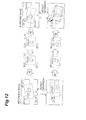
- FIG. 12 shows procedures in calculation processing for acquiring the position information of the second output area A12 of the first image sensor 11 and the second output area A22 of the second image sensor 12.
- the calculation processing in the output area acquisition section 50B will be described along with FIG. 12 .
- the output area acquisition section 50B acquires movement information based on the base image outputted from the movement information acquisition section 30, and acquires a base movement correction matrix C org through processing similar to that in Formula (5).
- an arbitrary coordinate (x, y) within the base image is multiplied by a normalized-matrix M -1 to convert the coordinate (x, y) into a coordinate (xn, yn) of the normal coordinate system.
- the output area acquisition section 50B multiplies the coordinate (xn, yn) by the denormalized matrix M' to convert the coordinate (xn, yn) into a coordinate (x', y') of the coordinate system of the reference image.
- the output area acquisition section 50B also acquires movement information based on the reference image outputted from the movement information acquisition section 30, and acquires a reference movement correction matrix C' org through processing similar to that in Formula (5).
- the output area acquisition section 50B multiplies the coordinate (x', y') by the reference movement correction matrix C' org to obtain a corrected coordinate (x'c, y'c).
- Moving amount and a moving direction from the coordinate (x', y') to the coordinate (x'c, y'c) are equivalent to moving amount and a moving direction of the second output area A22 with respect to the first output area A21.
- the output area acquisition section 50B acquires the position information of the second output area A22.
- the output area acquisition section 50B multiplies the coordinate (x'c, y'c) by a normalized matrix M' -1 to convert the coordinate (x'c, y'c) into a coordinate (x'nc, y'nc) of the normal coordinate system.
- the output area acquisition section 50B multiplies the coordinate (x'nc, y'nc) by the denormalized matrix M to convert the coordinate (x'nc, y'nc) into a coordinate (xc, yc) of the coordinate system of the base image.
- the output area acquisition section 50B calculates a weighted average between the base movement correction matrix C org obtained from the base image and the converted movement correction matrix C' conv , so as to obtain an average movement correction matrix C avr as shown in Formula (13).
- W org and W conv represent weights against the first image sensor 11 and the second image sensor 12, respectively. These weights are values set according to the reliability of the first image sensor 11 and the second image sensor 12. For example, when the first image sensor 11 is an infrared camera and the second image sensor 12 is a general visible light camera in the case of photo shooting at night time, the weight of the first image sensor 11 which is superior in photo shooting in the dark may be set heavier.
- the output area acquisition section 50B performs calculation of Formulas (1) to (4) and (6) to (9) shown in the first embodiment with use of the average movement correction matrix C avr obtained by Formula (13). As a result, position information of the second output area A12 of the base image and the second output area A22 of the reference image is acquired.
- the output area acquisition section 50B may also perform calculation of Formulas (10) and (11) shown in the second embodiment so as to prevent the second output areas A12 and A22 from being set outside the second frame image of the base image and the reference image.
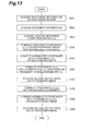
- steps S41, S42, S44, S45, S47 to S50 shown in FIG. 13 are identical to the operation in steps S11 to S14 and steps S16 to S19 shown in FIG. 7 respectively, the description thereof will be omitted.
- the output area acquisition section 50B performs acquisition processing of an average movement correction matrix C avr (S43).
- the procedures for acquisition processing of the average movement correction matrix C avr is shown in FIG. 14 .
- the output area acquisition section 50B converts an arbitrary coordinate (x, y) within the base image into a normal coordinate (S61).
- the output area acquisition section 50 converts the normal coordinate into a coordinate (x', y') within the reference image (S62).
- a denormalized matrix M' for use in conversion to the coordinate (x, y) within the base image is a value determined by placement information of the second image sensor 12.
- the output area acquisition section 50B converts the coordinate (x', y') into a coordinate (x'c, y'c) with a movement correction matrix C' conv determined by the movement information which was acquired by the movement information acquisition section 30 (S63).
- the output area acquisition section 50B converts the coordinate (x'c, y'c) into a normal coordinate (S64).
- the output area acquisition section 50B converts the normal coordinate into a coordinate (xc, yc) within the base image (S65).
- Formula (12) a converted movement correction matrix C conv is obtained by a series of processing from steps S61 to S65.
- the output area acquisition section 50B acquires the average movement correction matrix C avr by Formula (13) (S66).
- step S46 the output area acquisition section 50B converts the coordinate (x, y) into the coordinate (xc, yc) with the average movement correction matrix C avr (S46).
- the second output area A12 of the first image sensor 11 that is a base image sensor is acquired based on the position information of the first output area A11 determined by the placement information and based on the movement information
- the second output area A22 of the second image sensor 12, which is an image sensor different from the base image sensor, among the plurality of image sensors is acquired based on the placement information of the first image sensor 11, the placement information of the second image sensor 12, and the movement information.
- the second output area A12 of the first image sensor 11 and the second output area A22 of the second image sensor 12 are acquired based on the movement information which is common among the plurality of image sensors. Accordingly, correction processing can be performed with consistency among the images obtained from the plurality of image sensors.
- the image processing apparatus 1B of the present embodiment also acquires an average movement correction matrix C avr from a weighted average of the movement information obtained from the first image sensor 11 and the movement information obtained from the second image sensor 12.
- the movement information shown by the average movement correction matrix C avr is the information in consideration of the movement information acquired by the plurality of base image sensors, accurate movement information can be obtained.
- the output area acquisition section uses an area other than the output area which is needed because of using the plurality of image sensors as an area for performing hand shake correction.
- the area other than the output area may be used for an image processing operation different from the hand shake correction.
- the area other than the output area which is needed because of using the plurality of image sensors may be used as an area for use in correcting distortion generated by movement of the imaging section 10 and the object T.
- a distortion correction coefficient may be calculated in each of image sensors based on, for example, a motion vector in the base image, since the distortion correction coefficient is different in each of the image sensors.
- the movement information is acquired from the first frame image and the second frame image generated in the first image sensor 11 and the second image sensor 12.
- the movement information may be acquired by an external hardware such as a gyro sensor.
- the first image sensor 11 is used as a base image sensor and the second image sensor 12 is used as a reference image sensor.
- selection of an image sensor to be used as the base image sensor may be made based on image pickup conditions.
- a sensor selection section may be provided so as to select the first image sensor 11 as a base image sensor for photo shooting at night time or to select the second image sensor 12 as a base image sensor for photo shooting in the light. In this way, images of each of image sensors can be corrected with use of the information of an image sensor which is suitable for hand shake correction among the image sensors having different properties.
Landscapes
- Engineering & Computer Science (AREA)
- Physics & Mathematics (AREA)
- General Physics & Mathematics (AREA)
- Theoretical Computer Science (AREA)
- Multimedia (AREA)
- Signal Processing (AREA)
- Computer Vision & Pattern Recognition (AREA)
- Studio Devices (AREA)
- Image Processing (AREA)
- Testing, Inspecting, Measuring Of Stereoscopic Televisions And Televisions (AREA)
- Image Analysis (AREA)
Abstract
Description
- The present invention relates to an apparatus, a method, a program and a recording medium for image processing.
- Conventionally, an apparatus has been known which performs correction processing of moving images based on movement data between generated moving image frames. For example, disclosed below in
Patent Document 1 is an apparatus which calculates movement data between a base image and a reference image, calculates a pixel value difference between images in respective matching blocks based on the movement data, determines a superposing ratio between the base image and the reference image in every block based on the pixel value difference, and performs superposing processing to obtain a composite image, and thereby sharper and hand shake-corrected images are provided. - Patent Document 1: Japanese Patent Laid-Open No.
2009-164857 - A technology is known for combining images taken by a plurality of cameras so as to provide a three-dimensional image with a depth. A technology is also known which provides a three-dimensional moving image by generating and displaying such a three-dimensional image in succession. In such a three-dimensional moving image, it is required as in general moving images to perform correction processing such as hand shake correction and distortion correction. When the hand shake correction disclosed in
Patent Document 1 is performed on each of the images obtained from a plurality of image sensors, consistency in hand shake correction cannot be maintained among the images obtained from each of the image sensors, which may result in failure of implementing appropriate correction processing. - Accordingly, in this technical field, there is a demand for an apparatus, a method, a program and a recording medium for image processing which can perform correction processing consistent among images obtained from the plurality of image sensors.
- An image processing apparatus according to one aspect of the present invention is an image processing apparatus which performs image processing of a plurality of frame images generated by an imaging device having a plurality of image sensors each continuously generating a first frame image and a second frame image in sequence, comprising: a placement information acquisition section which acquires, for each image sensor, placement information indicating placement conditions of the image sensors with respect to the imaging device; a movement information acquisition section which acquires movement information of the imaging device between the first frame image and the second frame image; and an output area acquisition section which acquires, for each image sensor, position information of a second output area within the second frame image, the second output area corresponding to a first output area within the first frame image, wherein the output area acquisition section acquires: as a reference base, the second output area of a base image sensor among the plurality of image sensors based on the position information of the first output area determined by the placement information and based on the movement information; and the second output area of an image sensor being different from the base image sensor, among the plurality of image sensors based on the placement information of the base image sensor, the placement information of another image sensor, and the movement information.
- An image processing method according to one aspect of the present invention is an image processing method for performing image processing of a plurality of frame images generated by an imaging device having a plurality of image sensors which continuously generate a first frame image and a second frame image in sequence, comprising: a placement information acquisition step of acquiring, for every image sensor, placement information indicating placement conditions of the image sensors with respect to the imaging device; a movement information acquisition step of acquiring movement information of the imaging device between the first frame image and the second frame image; and an output area acquisition step of acquiring, for every image sensor, position information of a second output area within the second frame image which corresponds to a first output area within the first frame image, wherein in the output area acquisition step, as a reference base, the second output area of a base image sensor among the plurality of image sensors is acquired based on position information of the first output area determined by the placement information and based on the movement information, and the second output area of an image sensor being different from the base image sensor, among the plurality of image sensors is acquired based on placement information of the base image sensor, placement information of the other image sensor, and the movement information.
- An image processing program according to one aspect of the present invention is an image processing program for operating a computer to perform image processing of a plurality of frame images generated by an imaging device having a plurality of image sensors which continuously generate a first frame image and a second frame image in sequence, the program causing the computer to function as:
- a placement information acquisition section which acquires, for every image sensor, placement information indicating placement conditions of the image sensors with respect to the imaging device; a movement information acquisition section which acquires movement information of the imaging device between the first frame image and the second frame image; and an output area acquisition section which acquires, for every image sensor, position information of a second output area within the second frame image which corresponds to a first output area within the first frame image, wherein the output area acquisition section acquires: as a reference base, the second output area of a base image sensor among the plurality of image sensors based on position information of the first output area determined by the placement information and based on the movement information; and the second output area of an image sensor being different from the base image sensor, among the plurality of image sensors based on placement information of the base image sensor, placement information of the other image sensor, and the movement information.
- A computer readable storage medium having stored thereon an storage medium having stored thereon an image processing program for operating a computer to perform image processing of a plurality of frame images generated by an imaging device having a plurality of image sensors which continuously generate a first frame image and a second frame image in sequence, the program causing the computer to function as: a placement information acquisition section which acquires, for every image sensor, placement information indicating placement conditions of the image sensors with respect to the imaging device; a movement information acquisition section which acquires movement information of the imaging device between the first frame image and the second frame image; and an output area acquisition section which acquires, for every image sensor, position information of a second output area within the second frame image which corresponds to a first output area within the first frame image, wherein the output area acquisition section acquires: as a reference base, the second output area of a base image sensor among the plurality of image sensors based on position information of the first output area determined by the placement information and based on the movement information; and the second output area of an image sensor being different from the base image sensor, among the plurality of image sensors based on placement information of the base image sensor, placement information of the other image sensor, and the movement information.
- According to one aspect of such an invention, the second output area of the base image sensor is acquired based on position information of the first output area determined by the placement information and based on the movement information, and the second output area of an image sensor being different from the base image sensor, among the plurality of image sensors is acquired based on placement information of the base image sensor, placement information of the other image sensor, and the movement information. In this case, the second output area of the base image sensor and the second output area of the other image sensor are acquired based on the movement information which is common between these image sensors. Accordingly, correction processing can be performed with consistency among the images obtained from the plurality of image sensors.
- The apparatus may include a determination section which determines for all the image sensors whether or not the position information of the second output area is positioned within the second frame image, wherein when the position information of the second output area is not positioned within the second frame image, the output area acquisition section sets moving amount obtained by a difference between the position information of the first output area and the position information of the second output area to be smaller until the position information of the second output area is positioned within the second frame image in all the image sensors. As a result, it becomes possible to prevent inability of image processing due to the second output area not positioned within the second frame image.
- The movement information acquisition section may acquire the movement information from the first frame image and the second frame image generated by the base image sensor. In this case, since the movement information can be obtained from images, the movement information which is common among the plurality of image sensors can be acquired without adding a new hardware configuration.
- The movement information acquisition section may acquire the movement information by a gyro sensor. In this case, the movement information common among the plurality of image sensors can be acquired by the gyro sensor, and thereby a processing load can be reduced.
- The movement information acquisition section may acquire as the movement information a weighted average of the movement information acquired from the first frame image and the second frame image generated by the plurality of image sensors. In this case, the movement information is acquired based on the plurality of image sensors, and thereby the movement information can be acquired with sufficient accuracy.
- Moreover, the base image sensor may be selected from the plurality of image sensors based on image pickup conditions. In this case, by selecting, for example, an image sensor having sufficient performance as the base image sensor, the movement information can be acquired with sufficient accuracy.
- The output area acquisition section may use an area other than an output area being needed because of using the plurality of image sensors as an area for use in correction with movement. In this case, a margin for obtaining a three-dimensional image can also be used for correction with movement, and thereby a plurality of correction processes can be performed with one margin. Accordingly, it becomes possible to reduce decrease in the number of valid pixels after correction processing, which is caused by the necessity of securing the margin.
- According to one aspect of the present invention, it becomes possible to perform correction processing consistent among images obtained from the plurality of image sensors.
-
-
FIG. 1 is a view explaining the outline of hand shake correction by the plurality of image sensors; -
FIG. 2 is a block diagram showing a functional configuration of an image processing apparatus in a first embodiment; -
FIG. 3 is a view explaining placement information of a first image sensor and a second image sensor; -
FIG. 4 is a view showing a hardware configuration of the image processing apparatus; -
FIG. 5 is a view explaining movement information; -
FIG. 6 is a view showing procedures for calculation processing in an output area acquisition section; -
FIG. 7 is a flow chart showing acquisition processing of a second output area in the first embodiment; -
FIG. 8 is a block diagram showing a functional configuration of an image processing apparatus in a second embodiment; -
FIG. 9 is a view explaining a method for recalculating a movement correction matrix; -
FIG. 10 is a flow chart showing acquisition processing of a second output area in the second embodiment; -
FIG. 11 is a block diagram showing a functional configuration of an image processing apparatus in a third embodiment; -
FIG. 12 is a view showing procedures for acquisition processing of an average movement correction matrix; -
FIG. 13 is a flow chart showing acquisition processing of a second output area in the third embodiment; and -
FIG. 14 is a flow chart showing acquisition processing of an average movement correction matrix. - Hereinafter, embodiments of the present invention will be described with reference to the accompanying drawings. In descriptions of the drawings, the same reference numerals are given to the same or corresponding components and duplicated explanation will be omitted.
- An image processing apparatus of a first embodiment is an apparatus which performs hand shake correction processing being consistent among images inputted from the plurality of image sensors. The image processing apparatus is mounted on mobile phones, digital cameras, video cameras, or general computer systems. In one example, the apparatus is used for multiple cameras. In the present embodiment, a description is given of a configuration including two image sensors as an example of the plurality of image sensors.
- First of all, a description will be given of a method for acquiring a three-dimensional image from two image sensors for easy understanding of one aspect of the present invention.
FIG. 1 shows input frames generated by two image sensors, a first image sensor and a second image sensor, and output frames obtained by clipping a part of a pixel area of the input frames. Hereinafter, the areas clipped from a first frame and a second frame and generated by the first image sensor (first output areas) are respectively referred to as a first output area A11 and a second output area A12. The areas clipped from a first frame and a second frame and generated by the second image sensor (second output areas) are also respectively referred to as a first output area A21 and a second output area A22. In order to obtain a three-dimensional image with use of the first image sensor and the second image sensor, a specified image area which includes an object T is clipped as the first output area A11 from the first frame image generated by the first image sensor, and the first output area A21 corresponding to the first output area A11 is clipped from the first frame image generated by thesecond image sensor 12. A three-dimensional image is obtained from disparity information between the first output area A11 and the first output area A21. In this case, the position of the first output area A21 corresponding to the first output area A11 is uniquely determined by placement information, such as a placement position and a placement angle of the second image sensor with respect to the first image sensor. The position of the first output area A11 corresponding to the first output area A21 is uniquely determined by placement information, such as a placement position and a placement angle of the first image sensor with respect to the second image sensor. The placement information will be described later in detail. - The image processing apparatus according to the present embodiment detects movement information of an
imaging section 10 between the first frame image and the second frame image. Corresponding to moving amount of the imaging section, the image processing apparatus moves the position of the second output area A12 of the first image sensor and the position of the second output area A22 of the second image sensor, and acquires position information of the moved second output areas A12 and A22. In this case, if hand shake correction is independently performed on each of the image sensors, it is difficult to associate the second output area A12 with the second output area A22, which may result in failure of acquiring appropriate disparity information. Accordingly, in the image processing apparatus according to the present embodiment, moving amount of the output area obtained based on the movement information of one image sensor is reflected upon the output area of the other image sensor so as to implement consistent hand shake correction regardless of the placement information. Hereinafter, the image processing apparatus according to the present embodiment will be explained. -
FIG. 2 is a block diagram showing a functional configuration of animage processing apparatus 1 in the present embodiment. Theimage processing apparatus 1 is an apparatus which performs image processing of images generated by theimaging section 10 having the plurality of image sensors. Theimaging section 10 of the present embodiment includes two image sensors. - The
imaging section 10 includes afirst image sensor 11 and asecond image sensor 12. Thefirst image sensor 11 and thesecond image sensor 12 are means for generating an image of a subject. For example, theimaging section 10 comprises image sensors such as C-MOSs (Complementary Metal Oxide Semiconductors) and CCDs (Charged Coupled Devices) as its principal parts. Thefirst image sensor 11 and thesecond image sensor 12 continuously generate a first frame image and a second frame image in sequence. Thefirst image sensor 11 and thesecond image sensor 12 are placed at a specified interval and at a specified angle with each other as shown inFIGS. 3(a) and 3(b) . Theimaging section 10 placed in this way generates an identical image pickup object T as shown inFIG. 3(a) . - The
imaging section 10 is composed of a base image sensor which serves as a reference base, among the plurality of image sensors and a reference image sensor which is an image sensor different from the base image sensor. The image generated by the base image sensor is used at the time of generating movement information for use in performing correction processing of an image. In the present embodiment, thefirst image sensor 11 is used as a base image sensor while thesecond image sensor 12 is used as a reference image sensor. Thefirst image sensor 11 and thesecond image sensor 12 output generated first frame image and second frame image as image data to theimage processing apparatus 1. -
FIG. 4 is a view showing a hardware configuration of theimage processing apparatus 1. As shown inFIG. 4 , theimage processing apparatus 1 is physically configured as a general computer system including a CPU (Central Processing Unit) 100, a main memory device such as a ROM (Read Only Memory) 101 and a RAM (Random Access Memory) 102, aninput device 103 such as a keyboard, anoutput device 104 such as a display, and anauxiliary memory device 105 such as a hard disk. Later-described functions of theimage processing apparatus 1 are each implemented by causing the computer to read specified computer software into the hardware such as theCPU 100, theROM 101 and theRAM 102 and thereby theinput device 103 and theoutput device 104 are operated under control of theCPU 100 while causing the computer to read and write data from and onto the main memory device or theauxiliary memory device 105. Theimage processing apparatus 1 may include a communication module and the like. - Functionally, the
image processing apparatus 1 includes afirst input section 21, asecond input section 22, a movementinformation acquisition section 30, a placementinformation acquisition section 40, a placementinformation storage section 41, and an outputarea acquisition section 50 as shown inFIG. 2 . - The
first input section 21 represents a function of acquiring image data (hereinafter also referred to as a base image) generated by thefirst image sensor 11 that is a base image sensor. Thefirst input section 21 outputs a first frame image and a second frame image generated by the first image sensor to the movementinformation acquisition section 30 and to the outputarea acquisition section 50. - The
second input section 22 represents a function of acquiring image data (hereinafter also referred to as a reference image) generated by thesecond image sensor 12 that is a reference image sensor. Thesecond input section 22 acquires each of a first frame image and a second frame image generated by thesecond image sensor 12. Thesecond input section 22 outputs the first frame image and the second frame image generated by the second image sensor to the outputarea acquisition section 50. - The movement
information acquisition section 30 represents a function of acquiring movement information of theimaging section 10 between the first frame image and the second frame image. The movement information is a value calculated based on spatial displacement amount between the first frame image, used as reference, and the second frame image. In detail, the first frame image and the second frame image are divided into blocks of a specified size, and image signal patterns in respective blocks are searched to find the patterns which are most closely matched between the frames. Spatial displacement amount (motion vector) between the most closely matched image signal patterns between the frames is calculated as movement information. More specifically, as shown inFIG. 5 , the movementinformation acquisition section 30 acquires rotation amount θ of the second frame image with respect to the first frame image, shift amount of an image origin dx, dy, and magnified amount s as the movement information. The movementinformation acquisition section 30 outputs the acquired movement information to the outputarea acquisition section 50. - The placement
information acquisition section 40 acquires placement information indicating placement conditions of thefirst image sensor 11 and thesecond image sensor 12 with respect to theimaging section 10. The placement information refers to parameters representing a placement position, a placement angle and the like of the image sensors with respect to theimaging section 10. These parameters are set at the time of designing theimaging section 10. When theimaging section 10 and theimage processing apparatus 1 are connected, the placement information stored in theimaging section 10 is acquired and stored in the placementinformation storage section 41. The placementinformation acquisition section 40 acquires the placement information of thefirst image sensor 11 and thesecond image sensor 12 from the placementinformation storage section 41. The placementinformation acquisition section 40 outputs the acquired placement information of thefirst image sensor 11 and thesecond image sensor 12 to the outputarea acquisition section 50. Alternatively, the placementinformation acquisition section 40 may acquire the placement information directly from theimaging section 10. - The output
area acquisition section 50 acquires position information of the second output areas A12 and A22 within the second frame image, which correspond to first output areas A11 and A21 within the first frame image. The second output areas A12 and A22 corresponding to the first output areas A11 and A21 herein refer to the second output areas A12 and A22 which are the matches for the first output areas A11 and A21. The outputarea acquisition section 50 sets the positions of the second output areas A12 and A22 of the second frame image so that the second output areas A12 and A22 are not displaced from the first output areas A11 and A21 within the first frame image. The set positions of the second output areas A12 and A22 may be identical to the positions of the first output areas A11 and A21 or may be different from the positions of the first output areas A11 and A21. The outputarea acquisition section 50 acquires the second output area for each image sensor. Hereinafter, a description will be given of calculation processing for acquiring the position information of the second output area A12 of thefirst image sensor 11 and the second output area A22 of thesecond image sensor 12. -
FIG. 6 shows procedures in calculation processing for acquiring the position information of the second output area A12 of thefirst image sensor 11 and the second output area A22 of thesecond image sensor 12. The calculation processing of the outputarea acquisition section 50 will be described along withFIG. 6 . - First, the output
area acquisition section 50 converts an arbitrary coordinate (x', y') within the first frame image of the reference image into a coordinate (xn, yn) of a normal coordinate system by Formula (1). A normalized matrix is a matrix for converting the coordinate system of an inputted image to a normal coordinate system. A normalized-matrix M'-1 in Formula (1) is an inverse matrix of a denormalized matrix M' of thesecond image sensor 12 shown in Formula (2). The denormalized matrix M' is a matrix for converting the normal coordinate system to the coordinate system of the reference image. The denormalized matrix M' is obtained from clipping positions (x1', y1'), (x2', y2'), and (x3', y3') of the first output area A21 of the first frame image by thesecond image sensor 12. The denormalized matrix M' is determined by position information of thesecond image sensor 12 with respect to theimaging section 10 outputted from the placementinformation acquisition section 40. -

-

- Next, the output
area acquisition section 50 converts the coordinate (xn, yn) of the normal coordinate system into a coordinate (x, y) in a coordinate system of the first image sensor I by Formula (3). A denormalized matrix M in Formula (3) is a matrix for converting the normal matrix into a coordinate system of the base image. The denormalized matrix M is shown in Formula (4). The denormalized matrix M is obtained from clipping positions (x1, y1), (x2, y2), and (x3, y3) of the first output area A11 of the first frame image by thefirst image sensor 11. The denormalized matrix M is determined by position information of thefirst image sensor 11 with respect to theimaging section 10 outputted from the placementinformation acquisition section 40. -

-

- Next, the output
area acquisition section 50 calculates a movement correction matrix C shown in Formula (5) based on the movement information acquired from the movementinformation acquisition section 30. -

- Next, as shown in Formula (6), the output
area acquisition section 50 multiplies the coordinate (x, y) in the coordinate system of thefirst image sensor 11 by the movement correction matrix C to obtain a corrected coordinate (xc, yc) of thefirst image sensor 11. Moving amount and a moving direction from the coordinate (x, y) to the coordinate (xc, yc) are equivalent to moving amount and a moving direction of the second output area A12 with respect to the first output area A11. Thus, the outputarea acquisition section 50 acquires position information of the second output area A12 corresponding to the first output area A11. -

- Next, the output
area acquisition section 50 converts the corrected coordinate (xc, yc) in the coordinate system of thefirst image sensor 11 into a coordinate (xnc, ync) of the normal coordinate system by Formula (7). Then, the coordinate (xn, yn) in the normal coordinate system is converted into a corrected coordinate (x'c, y'c) in a coordinate system of thesecond image sensor 12 by Formula (8). Moving amount and a moving direction from the coordinate (x', y') to the coordinate (x'c, y'c) are equivalent to moving amount and a moving direction of the second output area A22 with respect to the first output area A21. Thus, the outputarea acquisition section 50 acquires position information of the second output area A22 corresponding to the first output area A21.
-

- The above-described calculation processing performed by the output
area acquisition section 50 can be summarized as shown below. That is, an arbitrary coordinate (x', y') within the first frame image of the reference image is converted into a corrected coordinate (x'c, y'c) according to Formula (9). When C' is equal to M'M-1CMM'-1 in Formula (9), C' becomes a movement correction matrix of thesecond image sensor 12 that is a reference image sensor. -

- Next, a description will be given of the operation of the
image processing apparatus 1 and a method for image processing according to the present embodiment with reference toFIG. 7 . - First, the placement
information acquisition section 40 acquires placement information of thefirst image sensor 11 and thesecond image sensor 12 from the placement information storage section 41 (S11). Next, the movementinformation acquisition section 30 acquires movement information from a first frame image and a second frame image of the base image from the first input section 21 (S12). Next, the outputarea acquisition section 50 converts an arbitrary coordinate (x', y') in the reference image into a normal coordinate (xn, yn) by Formula (1) (S13). Then, the outputarea acquisition section 50 converts the normal coordinate (xn, yn) into a coordinate (x, y) within the base image by Formula (3) (S14). In this case, a denormalized matrix M for use in conversion to the coordinate (x, y) of the base image is a value determined by the placement information of thefirst image sensor 11 with respect to theimaging section 10. - Next, the output
area acquisition section 50 converts, as shown in Formula (6), the coordinate (x, y) into a coordinate (xc, yc) with the movement correction matrix C determined by the movement information, which was acquired by the movement information acquisition section 30 (S15). Next, the outputarea acquisition section 50 acquires position information of the second output area A12 from moving amount of the coordinate (xc, yc) with respect to the coordinate (x, y) (S16). Next, the outputarea acquisition section 50 converts the coordinate (xc, yc) into a normal coordinate (xcn, ycn) by Formula (7) (S17). Then, the outputarea acquisition section 50 converts the normal coordinate (xcn, ycn) into a coordinate (x'c, y'c) within the reference image by Formula (8) (S18). Next, the outputarea acquisition section 50 acquires position information of the second output area A22 from moving amount of the coordinate (x'c, y'c) with respect to the coordinate (x', y') (S19). Once the position information of the second output area A12 is acquired, the image processing apparatus ends the image processing ofFIG. 7 . - Next, a description will be given of image processing program for causing a computer to function as the
image processing apparatus 1. - The image processing program includes a main module, an input module, a movement information acquisition module, a placement information acquisition module, a placement information storage module, and an output area acquisition module. The main module is a portion which performs comprehensive control on image processing. The input module operates the computer so that inputted images are acquired from the
first image sensor 11 and thesecond image sensor 12. Functions implemented by executing the movement information acquisition module, the placement information acquisition module, the placement information storage module, and the output area acquisition module are each similar to the functions of the movementinformation acquisition section 30, the placementinformation acquisition section 40, the placementinformation storage section 41, and the outputarea acquisition section 50. - The image processing program is provided in the form of, for example, a storage medium such as ROMs or a semiconductor memory. The image processing program may also be provided via a network as data signals.
- As described above, according to the present embodiment, the second output area A12 of the
first image sensor 11 that is a base image sensor is acquired based on the position information of the first output area A11 determined by the placement information and based on the movement information, and the second output area A22 of thesecond image sensor 12, which is an image sensor different from the base image sensor, among the plurality of image sensors is acquired based on the placement information of thefirst image sensor 11, the placement information of thesecond image sensor 12, and the movement information. Since the second output area A12 of thefirst image sensor 11 and the second output area A22 of thesecond image sensor 12 are acquired based on the movement information which is common between thefirst image sensor 11 and thesecond image sensor 12, it becomes possible to perform correction processing consistent between the images obtained from thefirst image sensor 11 and thesecond image sensor 12. Moreover, since a margin for use in obtaining a three-dimensional image is used as a margin for use in hand shake correction, it becomes possible to provide an output image which was hand shake corrected without narrowing an output area. - Next, a description will be given of an image processing apparatus according to a second embodiment. The image processing apparatus is different from that of the first embodiment in the following point. That is, when the position information of the second output areas A12 and A22 is not positioned within the second frame image, moving amount, which is obtained by a difference between the position information of the first output areas A11, A21 and the position information of the second output areas A12, A22, is adjusted to be small until the position information of the second output area is positioned within the second frame image in all the image sensors.
-
FIG. 8 is a block diagram showing a functional configuration of animage processing apparatus 1A according to the present embodiment. Theimage processing apparatus 1A according to the present embodiment includes an outputarea acquisition section 50A in place of the outputarea acquisition section 50. Moreover, thedetermination section 60 is provided in addition to theimage processing apparatus 1 according to the first embodiment. Other structural components are the same as those of the first embodiment. - The
determination section 60 has the function to determine whether or not the second output areas A12 and A22 in the second frames of the first and second imaging devices are positioned respectively within the second frame images. Thedetermination section 60 determines whether or not the coordinates of four apexes (xc1, yc1), (xc2, yc2), (xc3, yc3), and (xc4, yc4) of the second output area A12 calculated by Formula (6) are within the second frame image of thefirst image sensor 11. Thedetermination section 60 also determines whether or not the coordinates of four apexes (x'c1, y'c1) (x'c2, y'c2), (x'c3, y'c3) and (x'c4, y'c4) of the second output area A22 calculated by Formula (9) are within the second frame image generated by thesecond image sensor 12. When it is determined that the coordinate of at least one of four apexes is not within the second frame image in either one of the second output area A12 or the second output area A22, thedetermination section 60 outputs a deviation signal, indicating that the second output areas A12 and A22 are out of the second frame image, to the outputarea acquisition section 50A. - Upon reception of the deviation signal from the
determination section 60, the outputarea acquisition section 50A sets moving amount, which is obtained by a difference between the position information of the first output areas A11, A21 and the position information of the second output areas A12, A22, to be smaller until the position information of the second output areas A12, A22 is positioned within the second frame image in all the image sensors. A description will be hereinbelow given of recalculation for adjusting the position information of the second output areas A12 and A22 with reference toFIG. 9 . -
FIG. 9(a) shows an example in which the second output area A12 is positioned out of the second frame of thefirst image sensor 11. In this example, a coordinate C (x3, y3) and a coordinate C (x4, y4) of the second output area A12 are positioned out of the second frame. In this case, the outputarea acquisition section 50A calculates a frame inside/outside ratio r. Hereinafter, a frame inside/outside ratio r of the coordinate C (x3, y3) is calculated. However, a frame inside/outside ratio r of the coordinate C (x4, y4) may be calculated instead. - When a coordinate of the first output area is connected by a straight line to a coordinate which corresponds to the coordinate of the first output area and which positions out of the second frame, the frame inside/outside ratio r is defined as a ratio between a length of a portion of the straight line inside the second frame and a length of a portion of the straight line outside the second frame. The output
area acquisition section 50A calculates the frame inside/outside ratio r, and then updates the correction matrix C by Formula (10). In Formula (10), I represents a unit matrix. The outputarea acquisition section 50A then multiplies a coordinate (x, y) in a coordinate system of the base image by the updated movement correction matrix C so as to acquire position information of the second output area A12. The outputarea acquisition section 50A also acquires position information of the second output area A22 based on the position information of the updated second output area A12 by Formulas (7) and (8). -

- Then, the
determination section 60 again determines whether or not four apexes of the second output area A12 determined by the updated correction matrix C are within the second frame image of thefirst image sensor 11, and updates the correction matrix by Formula (10) until all the apexes are positioned within the second frame image. Thedetermination section 60 also acquires the second output area A12 and the second output area A22 based on the updated correction matrix. When it is determined in thedetermination section 60 that the coordinates of all the apexes are within the second frame image, the second output area A12 and the second output area A22 at that point of time are outputted. -
FIG. 9(b) shows an example in which the second output area A22 is positioned out of the second frame of thesecond image sensor 12. In this example, a coordinate C' (x'3, y'3) and a coordinate C' (x'4, y'4) of the second output areas A12 are positioned out of the second frame. In this case, the outputarea acquisition section 50A calculates the frame inside/outside ratio r'. Hereinafter, a frame inside/outside ratio r of the coordinate C' (x'4, y'4) is calculated. However, a frame inside/outside ratio r of the coordinate C' (x'3, y'3) may be calculated instead. - The output
area acquisition section 50A calculates the frame inside/outside ratio r', and then updates the correction matrix C by Formula (11). The outputarea acquisition section 50A then multiplies a coordinate (x, y) in the coordinate system of thefirst image sensor 11 by the updated movement correction matrix C so as to acquire the position information of the second output area A12. The outputarea acquisition section 50A also acquires the position information of the second output area A22 based on the position information of the updated second output area A12 by Formulas (7) and (8). -

- Then, the
determination section 60 again determines whether or not four apexes of the second output area A12 determined by the updated correction matrix C are within the second frame image of thefirst image sensor 11, and updates the correction matrix by Formula (11) until all the apexes are positioned within the second frame image. Thedetermination section 60 also acquires the second output area A12 and the second output area A22 based on the updated correction matrix. When it is determined in thedetermination section 60 that the coordinates of all the apexes are within the second frame image, the second output area A12 and the second output area A22 at that point of time are outputted. - Next, a description will be given of the operation of the
image processing apparatus 1A and a method for image processing according to the present embodiment with reference toFIG. 10 . - Since steps S21 to S26 and steps S28 to S30 shown in
FIG. 10 are identical to the operation in steps S11 to S19 shown inFIG. 7 , respectively, descriptions thereof will be omitted. Once the second output area A12 of the base image is acquired in S26, the outputarea acquisition section 50A determines whether or not the second output area A12 of the base image is positioned within the base image (S27). When it is determined that the second output area A12 of the base image is positioned out of the base image, the outputarea acquisition section 50A recalculates the correction matrix C by Formula (10) (S32), and then processing shifts to step S25. When it is determined that the second output area A12 of the base image is positioned within the base image, then processing shifts to step S28. - Once the second output area A22 of the reference image is acquired in step S30, the output
area acquisition section 50A determines whether or not the second output area A22 of the reference image is positioned within the reference image (S31). When it is determined that the second output area A22 of the reference image is positioned out of the reference image, the outputarea acquisition section 50A recalculates the correction matrix C by Formula (11) (S32), and then processing shifts to step S25. When it is determined that the second output area A22 of the reference image is positioned within the reference image, then the image processing shown inFIG. 10 is ended. - As described above, according to the present embodiment, the second output area A12 of the
first image sensor 11 that is a base image sensor is acquired based on the position information of the first output area A11 determined by the placement information and based on the movement information, and the second output area A22 of thesecond image sensor 12, which is an image sensor different from the base image sensor, among the plurality of image sensors is acquired based on the placement information of thefirst image sensor 11, the placement information of thesecond image sensor 12, and the movement information. In this case, the second output area A12 of thefirst image sensor 11 and the second output area A22 of thesecond image sensor 12 are acquired based on the movement information which is common among the plurality of image sensors. Accordingly, correction processing can be performed with consistency among the images obtained from the plurality of image sensors. - The
image processing apparatus 1A of the present embodiment also includes adetermination section 60 which determines for all the image sensors whether or not position information of the second output areas A11 and A12 is positioned within the second frame image. When the position information of the second output areas A12 and A22 is not positioned within the second frame image, the outputarea acquisition section 50A sets moving amount, which is obtained by a difference between the position information of the first output area and the position information of the second output area, to be smaller until the position information of the second output area is positioned within the second frame image in all the image sensors. As a result, it becomes possible to prevent inability of image processing due to the second output areas A11 and A12 not positioned within the second frame image. - Next, a description will be given of an image processing apparatus according to a third embodiment. The image processing apparatus according to the present embodiment is different from that of the first embodiment in the point that movement information is acquired in the plurality of image sensors, and the movement information acquired in each imaging sensor is weight-averaged and is then used to obtain position information of the second output area.
-
FIG. 11 is a block diagram showing a functional configuration of animage processing apparatus 1B according to the present embodiment. Theimage processing apparatus 1B according to the present embodiment includes an outputarea acquisition section 50B in place of the outputarea acquisition section 50. In theimage processing apparatus 1B according to the present embodiment, thesecond input section 22 outputs a reference image acquired from thesecond image sensor 12 to the movementinformation acquisition section 30. The movementinformation acquisition section 30 acquires movement information of theimaging section 10 between a first frame image and a second frame image of a base image acquired from thefirst input section 21 and movement information of theimaging section 10 between a first frame image and a second frame image of a reference image acquired from thesecond input section 22. The movementinformation acquisition section 30 of the present embodiment outputs the movement information obtained from the base image and the movement information obtained from the reference image to the outputarea acquisition section 50B. - The output
area acquisition section 50B acquires, for each image sensor, position information of the second output area within the second frame image, which corresponds to the first output area within the first frame image. Hereinafter, a description will be given of calculation processing for acquiring position information of the second output area A12 of thefirst image sensor 11 and the second output area A22 of thesecond image sensor 12. -
FIG. 12 shows procedures in calculation processing for acquiring the position information of the second output area A12 of thefirst image sensor 11 and the second output area A22 of thesecond image sensor 12. The calculation processing in the outputarea acquisition section 50B will be described along withFIG. 12 . - First, the output
area acquisition section 50B acquires movement information based on the base image outputted from the movementinformation acquisition section 30, and acquires a base movement correction matrix Corg through processing similar to that in Formula (5). - Next, an arbitrary coordinate (x, y) within the base image is multiplied by a normalized-matrix M-1 to convert the coordinate (x, y) into a coordinate (xn, yn) of the normal coordinate system. Next, the output
area acquisition section 50B multiplies the coordinate (xn, yn) by the denormalized matrix M' to convert the coordinate (xn, yn) into a coordinate (x', y') of the coordinate system of the reference image. - The output
area acquisition section 50B also acquires movement information based on the reference image outputted from the movementinformation acquisition section 30, and acquires a reference movement correction matrix C'org through processing similar to that in Formula (5). Next, as shown in Formula (6), the outputarea acquisition section 50B multiplies the coordinate (x', y') by the reference movement correction matrix C'org to obtain a corrected coordinate (x'c, y'c). Moving amount and a moving direction from the coordinate (x', y') to the coordinate (x'c, y'c) are equivalent to moving amount and a moving direction of the second output area A22 with respect to the first output area A21. Thus, the outputarea acquisition section 50B acquires the position information of the second output area A22. - Then, the output
area acquisition section 50B multiplies the coordinate (x'c, y'c) by a normalized matrix M'-1 to convert the coordinate (x'c, y'c) into a coordinate (x'nc, y'nc) of the normal coordinate system. Next, the outputarea acquisition section 50B multiplies the coordinate (x'nc, y'nc) by the denormalized matrix M to convert the coordinate (x'nc, y'nc) into a coordinate (xc, yc) of the coordinate system of the base image. - When the movement correction matrix for moving the first output area A11 of the base image to the second output area A12 is defined as a converted movement correction matrix C'conv, the calculation processing performed by the output
area acquisition section 50B up to this point can be expressed by Formula (12). -

- At this point, the output
area acquisition section 50B calculates a weighted average between the base movement correction matrix Corg obtained from the base image and the converted movement correction matrix C'conv, so as to obtain an average movement correction matrix Cavr as shown in Formula (13). In Formula (13), Worg and Wconv represent weights against thefirst image sensor 11 and thesecond image sensor 12, respectively. These weights are values set according to the reliability of thefirst image sensor 11 and thesecond image sensor 12. For example, when thefirst image sensor 11 is an infrared camera and thesecond image sensor 12 is a general visible light camera in the case of photo shooting at night time, the weight of thefirst image sensor 11 which is superior in photo shooting in the dark may be set heavier. -

- Then, the output
area acquisition section 50B performs calculation of Formulas (1) to (4) and (6) to (9) shown in the first embodiment with use of the average movement correction matrix Cavr obtained by Formula (13). As a result, position information of the second output area A12 of the base image and the second output area A22 of the reference image is acquired. The outputarea acquisition section 50B may also perform calculation of Formulas (10) and (11) shown in the second embodiment so as to prevent the second output areas A12 and A22 from being set outside the second frame image of the base image and the reference image. - Next, a description will be given of operation of the
image processing apparatus 1B and a method for image processing according to the present embodiment with reference toFIGS. 13 and14 . - Since steps S41, S42, S44, S45, S47 to S50 shown in
FIG. 13 are identical to the operation in steps S11 to S14 and steps S16 to S19 shown inFIG. 7 respectively, the description thereof will be omitted. Once the movement information is acquired in S26, the outputarea acquisition section 50B performs acquisition processing of an average movement correction matrix Cavr (S43). The procedures for acquisition processing of the average movement correction matrix Cavr is shown inFIG. 14 . - In the acquisition processing of the average movement correction matrix Cavr, the output
area acquisition section 50B converts an arbitrary coordinate (x, y) within the base image into a normal coordinate (S61). Next, the outputarea acquisition section 50 converts the normal coordinate into a coordinate (x', y') within the reference image (S62). In this case, a denormalized matrix M' for use in conversion to the coordinate (x, y) within the base image is a value determined by placement information of thesecond image sensor 12. - Next, the output
area acquisition section 50B converts the coordinate (x', y') into a coordinate (x'c, y'c) with a movement correction matrix C'conv determined by the movement information which was acquired by the movement information acquisition section 30 (S63). Next, the outputarea acquisition section 50B converts the coordinate (x'c, y'c) into a normal coordinate (S64). Then, the outputarea acquisition section 50B converts the normal coordinate into a coordinate (xc, yc) within the base image (S65). As shown in Formula (12), a converted movement correction matrix Cconv is obtained by a series of processing from steps S61 to S65. Next, the outputarea acquisition section 50B acquires the average movement correction matrix Cavr by Formula (13) (S66). - Then, the processing returns to the procedures of
FIG. 13 . In step S46, the outputarea acquisition section 50B converts the coordinate (x, y) into the coordinate (xc, yc) with the average movement correction matrix Cavr (S46). - As described above, also in the present embodiment, the second output area A12 of the
first image sensor 11 that is a base image sensor is acquired based on the position information of the first output area A11 determined by the placement information and based on the movement information, and the second output area A22 of thesecond image sensor 12, which is an image sensor different from the base image sensor, among the plurality of image sensors is acquired based on the placement information of thefirst image sensor 11, the placement information of thesecond image sensor 12, and the movement information. In this case, the second output area A12 of thefirst image sensor 11 and the second output area A22 of thesecond image sensor 12 are acquired based on the movement information which is common among the plurality of image sensors. Accordingly, correction processing can be performed with consistency among the images obtained from the plurality of image sensors. - The
image processing apparatus 1B of the present embodiment also acquires an average movement correction matrix Cavr from a weighted average of the movement information obtained from thefirst image sensor 11 and the movement information obtained from thesecond image sensor 12. In this case, since the movement information shown by the average movement correction matrix Cavr is the information in consideration of the movement information acquired by the plurality of base image sensors, accurate movement information can be obtained. - In the embodiments disclosed above, the output area acquisition section uses an area other than the output area which is needed because of using the plurality of image sensors as an area for performing hand shake correction. Here, the area other than the output area may be used for an image processing operation different from the hand shake correction. For example, the area other than the output area which is needed because of using the plurality of image sensors may be used as an area for use in correcting distortion generated by movement of the
imaging section 10 and the object T. When the placement positions of imaging sensors are displaced, a distortion correction coefficient may be calculated in each of image sensors based on, for example, a motion vector in the base image, since the distortion correction coefficient is different in each of the image sensors. - Although the present invention has been described in detail based on the embodiments thereof, the present invention is not limited to the embodiments disclosed. Various deformations are possible in the present invention without departing from the scope thereof.
- For example, in the above embodiments, the movement information is acquired from the first frame image and the second frame image generated in the
first image sensor 11 and thesecond image sensor 12. However, the movement information may be acquired by an external hardware such as a gyro sensor. - In the above embodiments, the
first image sensor 11 is used as a base image sensor and thesecond image sensor 12 is used as a reference image sensor. However, selection of an image sensor to be used as the base image sensor may be made based on image pickup conditions. For example, when thefirst image sensor 11 is an infrared camera and thesecond image sensor 12 is a general visible light camera, a sensor selection section may be provided so as to select thefirst image sensor 11 as a base image sensor for photo shooting at night time or to select thesecond image sensor 12 as a base image sensor for photo shooting in the light. In this way, images of each of image sensors can be corrected with use of the information of an image sensor which is suitable for hand shake correction among the image sensors having different properties.
Claims (10)
- An image processing apparatus which performs image processing of a plurality of frame images generated by an imaging device having a plurality of image sensors each continuously generating a first frame image and a second frame image in sequence, comprising:a placement information acquisition section which acquires, for each image sensor, placement information indicating placement conditions of the image sensors with respect to the imaging device;a movement information acquisition section which acquires movement information of the imaging device between the first frame image and the second frame image; andan output area acquisition section which acquires, for each image sensor, position information of a second output area within the second frame image, the second output area corresponding to a first output area within the first frame image, whereinthe output area acquisition section acquires:as a reference base, the second output area of a base image sensor among the plurality of image sensors based on the position information of the first output area determined by the placement information and based on the movement information; andthe second output area of an image sensor being different from the base image sensor, among the plurality of image sensors based on the placement information of the base image sensor, the placement information of another image sensor, and the movement information.
- The image processing apparatus according to claim 1, comprising:a determination section which determines for all the image sensors whether or not the position information of the second output area is positioned within the second frame image, whereinwhen the position information of the second output area is not positioned within the second frame image, the output area acquisition section sets moving amount obtained by a difference between the position information of the first output area and the position information of the second output area to be smaller until the position information of the second output area is positioned within the second frame image in all the image sensors.
- The image processing apparatus according to claim 1 or 2, wherein
the movement information acquisition section acquires the movement information from the first frame image and the second frame image generated in the base image sensor. - The image processing apparatus according to claim 1 or 2, wherein
the movement information acquisition section acquires the movement information by a gyro sensor. - The image processing apparatus according to claim 1 or 2, wherein
the movement information acquisition section acquires as the movement information a weighted average of the movement information acquired from the first frame image and the second frame image generated by the plurality of image sensors. - The image processing apparatus according to any one of claims 1 to 5, wherein
the base image sensor is selected out of the plurality of image sensors based on image pickup conditions. - The image processing apparatus according to any one of claims 1 to 6, wherein
the output area acquisition section uses an area other than the output area being needed because of using the plurality of image sensors, as an area for use in correction with movement. - An image processing method for performing image processing of a plurality of frame images generated by an imaging device having a plurality of image sensors which continuously generate a first frame image and a second frame image in sequence, comprising:a placement information acquisition step of acquiring, for every image sensor, placement information indicating placement conditions of the image sensors with respect to the imaging device;a movement information acquisition step of acquiring movement information of the imaging device between the first frame image and the second frame image; andan output area acquisition step of acquiring, for every image sensor, position information of a second output area within the second frame image which corresponds to a first output area within the first frame image, whereinin the output area acquisition step,as a reference base, the second output area of a base image sensor among the plurality of image sensors is acquired based on position information of the first output area determined by the placement information and based on the movement information, andthe second output area of an image sensor being different from the base image sensor, among the plurality of image sensors is acquired based on placement information of the base image sensor, placement information of the other image sensor, and the movement information.
- An image processing program for operating a computer to perform image processing of a plurality of frame images generated by an imaging device having a plurality of image sensors which continuously generate a first frame image and a second frame image in sequence, the program causing the computer to function as:a placement information acquisition section which acquires, for every image sensor, placement information indicating placement conditions of the image sensors with respect to the imaging device;a movement information acquisition section which acquires movement information of the imaging device between the first frame image and the second frame image; andan output area acquisition section which acquires, for every image sensor, position information of a second output area within the second frame image which corresponds to a first output area within the first frame image, whereinthe output area acquisition section acquires:as a reference base, the second output area of a base image sensor among the plurality of image sensors based on position information of the first output area determined by the placement information and based on the movement information; andthe second output area of an image sensor being different from the base image sensor, among the plurality of image sensors based on placement information of the base image sensor, placement information of the other image sensor, and the movement information.
- A storage medium having stored thereon an image processing program for operating a computer to perform image processing of a plurality of frame images generated by an imaging device having a plurality of image sensors which continuously generate a first frame image and a second frame image in sequence, the program causing the computer to function as:a placement information acquisition section which acquires, for every image sensor, placement information indicating placement conditions of the image sensors with respect to the imaging device;a movement information acquisition section which acquires movement information of the imaging device between the first frame image and the second frame image; andan output area acquisition section which acquires, for every image sensor, position information of a second output area within the second frame image which corresponds to a first output area within the first frame image, whereinthe output area acquisition section acquires:as a reference base, the second output area of a base image sensor among the plurality of image sensors based on position information of the first output area determined by the placement information and based on the movement information; andthe second output area of an image sensor being different from the base image sensor, among the plurality of image sensors based on placement information of the base image sensor, placement information of the other image sensor, and the movement information.
Applications Claiming Priority (1)
| Application Number | Priority Date | Filing Date | Title |
|---|---|---|---|
| JP2011220269A JP5412692B2 (en) | 2011-10-04 | 2011-10-04 | Image processing apparatus, image processing method, image processing program, and recording medium |
Publications (3)
| Publication Number | Publication Date |
|---|---|
| EP2579213A2 true EP2579213A2 (en) | 2013-04-10 |
| EP2579213A3 EP2579213A3 (en) | 2017-11-22 |
| EP2579213B1 EP2579213B1 (en) | 2019-04-10 |
Family
ID=47325808
Family Applications (1)
| Application Number | Title | Priority Date | Filing Date |
|---|---|---|---|
| EP12187292.3A Not-in-force EP2579213B1 (en) | 2011-10-04 | 2012-10-04 | Apparatus, method, program and recording medium for image processing |
Country Status (4)
| Country | Link |
|---|---|
| US (1) | US9117271B2 (en) |
| EP (1) | EP2579213B1 (en) |
| JP (1) | JP5412692B2 (en) |
| CN (1) | CN103037158B (en) |
Families Citing this family (13)
| Publication number | Priority date | Publication date | Assignee | Title |
|---|---|---|---|---|
| JP6153318B2 (en) * | 2012-11-30 | 2017-06-28 | キヤノン株式会社 | Image processing apparatus, image processing method, image processing program, and storage medium |
| EP2757527B1 (en) * | 2013-01-16 | 2018-12-12 | Honda Research Institute Europe GmbH | System and method for distorted camera image correction |
| FR3023956B1 (en) * | 2014-07-18 | 2018-01-12 | Safran Electronics & Defense Sas | METHOD AND DEVICE FOR PROCESSING HIGH FREQUENCY MOVEMENTS IN AN OPTRONIC SYSTEM |
| CN104093014A (en) * | 2014-07-21 | 2014-10-08 | 宇龙计算机通信科技(深圳)有限公司 | Image processing method and image processing device |
| DE102014115292A1 (en) * | 2014-10-21 | 2016-04-21 | Connaught Electronics Ltd. | Method for providing image files from a camera system, camera system and motor vehicle |
| EP3238447B1 (en) * | 2014-12-22 | 2021-10-27 | Cyberoptics Corporation | Updating calibration of a three-dimensional measurement system |
| US20170364197A1 (en) * | 2014-12-30 | 2017-12-21 | Shenzhen Royole Technologies Co. Ltd. | Touch operating methods, touch operation assembly, and electronic device |
| JP2017107488A (en) * | 2015-12-11 | 2017-06-15 | ルネサスエレクトロニクス株式会社 | Scanning system, scan image processing device, and scanning method |
| JP6629454B2 (en) * | 2015-12-28 | 2020-01-15 | 華為技術有限公司Huawei Technologies Co.,Ltd. | Image fusion method and device, and terminal device |
| JP6652300B2 (en) * | 2016-01-14 | 2020-02-19 | キヤノン株式会社 | Image processing apparatus, imaging apparatus, and control method |
| JP6769859B2 (en) * | 2016-12-19 | 2020-10-14 | 株式会社日立エルジーデータストレージ | Image processing device and image processing method |
| IL326284A (en) | 2018-09-24 | 2026-04-01 | Janssen Biotech Inc | Safe and effective method of treating ulcerative colitis with anti-il12/il23 antibody |
| JP7689074B2 (en) | 2019-01-15 | 2025-06-05 | ヤンセン バイオテツク,インコーポレーテツド | Anti-TNF antibodies, compositions, and methods for the treatment of juvenile idiopathic arthritis |
Citations (1)
| Publication number | Priority date | Publication date | Assignee | Title |
|---|---|---|---|---|
| JP2009164857A (en) | 2007-12-29 | 2009-07-23 | Morpho Inc | Image data processing method and image processing apparatus |
Family Cites Families (39)
| Publication number | Priority date | Publication date | Assignee | Title |
|---|---|---|---|---|
| JPH08317424A (en) * | 1995-05-19 | 1996-11-29 | Olympus Optical Co Ltd | Stereoscopic photographing device |
| JPH08336165A (en) * | 1995-06-09 | 1996-12-17 | Canon Inc | Compound eye imaging device |
| US6269175B1 (en) * | 1998-08-28 | 2001-07-31 | Sarnoff Corporation | Method and apparatus for enhancing regions of aligned images using flow estimation |
| US7605940B2 (en) * | 1999-09-17 | 2009-10-20 | Silverbrook Research Pty Ltd | Sensing device for coded data |
| US7128270B2 (en) * | 1999-09-17 | 2006-10-31 | Silverbrook Research Pty Ltd | Scanning device for coded data |
| CA2647018A1 (en) * | 1999-12-28 | 2001-07-05 | Sony Corporation | Signal processing device and method, and recording medium |
| JP2004037239A (en) * | 2002-07-03 | 2004-02-05 | Fuji Heavy Ind Ltd | Method and apparatus for determining same object, and method and apparatus for correcting displacement |
| JP4214459B2 (en) * | 2003-02-13 | 2009-01-28 | ソニー株式会社 | Signal processing apparatus and method, recording medium, and program |
| JP4144374B2 (en) * | 2003-02-25 | 2008-09-03 | ソニー株式会社 | Image processing apparatus and method, recording medium, and program |
| JP4265237B2 (en) * | 2003-02-27 | 2009-05-20 | ソニー株式会社 | Image processing apparatus and method, learning apparatus and method, recording medium, and program |
| JP4144378B2 (en) * | 2003-02-28 | 2008-09-03 | ソニー株式会社 | Image processing apparatus and method, recording medium, and program |
| JP4144377B2 (en) * | 2003-02-28 | 2008-09-03 | ソニー株式会社 | Image processing apparatus and method, recording medium, and program |
| US7746404B2 (en) * | 2003-11-10 | 2010-06-29 | Hewlett-Packard Development Company, L.P. | Digital camera with panoramic image capture |
| US8013909B2 (en) * | 2004-12-29 | 2011-09-06 | Nokia Corporation | Method and apparatus for adjusting exposure in digital imaging |
| KR20080003339A (en) * | 2005-03-14 | 2008-01-07 | 지테크 로드아일랜드 코포레이션 | Systems and Methods for Processing Forms |
| US7404645B2 (en) * | 2005-06-20 | 2008-07-29 | Digital Display Innovations, Llc | Image and light source modulation for a digital display system |
| JP2007215114A (en) * | 2006-02-13 | 2007-08-23 | Sony Corp | Captured image distortion correction method, captured image distortion correction apparatus, and imaging apparatus |
| EP1865730A3 (en) * | 2006-06-06 | 2010-01-20 | Sony Corporation | Video-signal processing method, program of video-signal processing method, recording medium having recorded thereon program of video-signal processing method, and video-signal processing apparatus |
| TWI316643B (en) * | 2006-07-14 | 2009-11-01 | Asia Optical Co Inc | Camera systems and methods with vibration compensation |
| JP2009545818A (en) * | 2006-07-31 | 2009-12-24 | オンライブ インコーポレイテッド | System and method for performing motion capture and image reconstruction |
| WO2008054217A1 (en) * | 2006-11-03 | 2008-05-08 | Tele Atlas B.V. | Method and apparatus for identification and position determination of planar objects in images |
| DE102006062061B4 (en) * | 2006-12-29 | 2010-06-10 | Fraunhofer-Gesellschaft zur Förderung der angewandten Forschung e.V. | Apparatus, method and computer program for determining a position based on a camera image from a camera |
| JP4714176B2 (en) * | 2007-03-29 | 2011-06-29 | 富士フイルム株式会社 | Stereoscopic apparatus and optical axis adjustment method |
| JP2009232276A (en) * | 2008-03-24 | 2009-10-08 | Olympus Imaging Corp | Image pickup device |
| JP4771186B2 (en) * | 2008-06-20 | 2011-09-14 | 国立大学法人静岡大学 | Movement amount extraction device and program, image correction device and program, and recording medium |
| JP5213613B2 (en) * | 2008-09-26 | 2013-06-19 | キヤノン株式会社 | Image processing apparatus, image processing method, imaging apparatus, and program |
| JP4852591B2 (en) * | 2008-11-27 | 2012-01-11 | 富士フイルム株式会社 | Stereoscopic image processing apparatus, method, recording medium, and stereoscopic imaging apparatus |
| JP2010252046A (en) * | 2009-04-15 | 2010-11-04 | Olympus Imaging Corp | Image pickup apparatus |
| US8886206B2 (en) * | 2009-05-01 | 2014-11-11 | Digimarc Corporation | Methods and systems for content processing |
| JP5380184B2 (en) * | 2009-07-09 | 2014-01-08 | 富士フイルム株式会社 | Compound eye camera and control method thereof |
| JP2011024003A (en) * | 2009-07-16 | 2011-02-03 | Fujifilm Corp | Three-dimensional moving image recording method and apparatus, and moving image file conversion method and apparatus |
| CN201540451U (en) * | 2009-09-25 | 2010-08-04 | 深圳市掌网立体时代视讯技术有限公司 | Optical anti-shake device of stereoscopic digital camera and anti-shake stereoscopic digital camera |
| US20120019614A1 (en) * | 2009-12-11 | 2012-01-26 | Tessera Technologies Ireland Limited | Variable Stereo Base for (3D) Panorama Creation on Handheld Device |
| CN102812712B (en) * | 2010-03-24 | 2015-04-08 | 富士胶片株式会社 | Image processing device and image processing method |
| JP5394296B2 (en) * | 2010-03-25 | 2014-01-22 | 富士フイルム株式会社 | Imaging apparatus and image processing method |
| US9438886B2 (en) * | 2010-04-07 | 2016-09-06 | Vision Iii Imaging, Inc. | Parallax scanning methods for stereoscopic three-dimensional imaging |
| JP2012114896A (en) * | 2010-11-04 | 2012-06-14 | Panasonic Corp | Three-dimensional imaging apparatus and three-dimensional reproduction apparatus |
| CN102006493A (en) * | 2010-11-26 | 2011-04-06 | 北京新岸线网络技术有限公司 | Parallax adjustment method and device for 3D video image |
| US8274552B2 (en) * | 2010-12-27 | 2012-09-25 | 3Dmedia Corporation | Primary and auxiliary image capture devices for image processing and related methods |
-
2011
- 2011-10-04 JP JP2011220269A patent/JP5412692B2/en not_active Expired - Fee Related
-
2012
- 2012-09-28 CN CN201210368095.3A patent/CN103037158B/en not_active Expired - Fee Related
- 2012-10-04 EP EP12187292.3A patent/EP2579213B1/en not_active Not-in-force
- 2012-10-04 US US13/644,309 patent/US9117271B2/en active Active
Patent Citations (1)
| Publication number | Priority date | Publication date | Assignee | Title |
|---|---|---|---|---|
| JP2009164857A (en) | 2007-12-29 | 2009-07-23 | Morpho Inc | Image data processing method and image processing apparatus |
Also Published As
| Publication number | Publication date |
|---|---|
| EP2579213A3 (en) | 2017-11-22 |
| JP5412692B2 (en) | 2014-02-12 |
| JP2013081091A (en) | 2013-05-02 |
| US20130083171A1 (en) | 2013-04-04 |
| CN103037158B (en) | 2016-01-20 |
| EP2579213B1 (en) | 2019-04-10 |
| CN103037158A (en) | 2013-04-10 |
| US9117271B2 (en) | 2015-08-25 |
Similar Documents
| Publication | Publication Date | Title |
|---|---|---|
| EP2579213B1 (en) | Apparatus, method, program and recording medium for image processing | |
| US11184603B2 (en) | Method for performing out-focus using depth information and camera using the same | |
| EP2403235B1 (en) | Image correction device and image correction method | |
| JP4218022B2 (en) | How to generate composite images | |
| EP2613290B1 (en) | Image processing device, image processing method, and image processing program | |
| US9600863B2 (en) | Method for combining images | |
| US8860852B2 (en) | Image capturing apparatus | |
| JP4196216B2 (en) | Image composition system, image composition method and program | |
| JP4717863B2 (en) | Calibration method and apparatus for compound eye imaging apparatus and calibration chart used therefor | |
| JP6053347B2 (en) | Imaging apparatus, control method therefor, and program | |
| US20190228555A1 (en) | Image processing apparatus that performs an alignment process on a plurality of images, a related control method, and a related storage medium that stores a control program | |
| CN104243794A (en) | Real-time image processing method and device | |
| JP6526273B2 (en) | Image processing apparatus, image processing method, and imaging apparatus | |
| US20120105658A1 (en) | Imaging device, image processing device, and image processing method | |
| US8179431B2 (en) | Compound eye photographing apparatus, control method therefor, and program | |
| EP1816854A1 (en) | Image pickup device, image pickup system and image photographing method | |
| JP2017049947A (en) | Image processing apparatus and image processing method | |
| JP6271969B2 (en) | Imaging apparatus and image correction method | |
| JP2020150405A (en) | Image processing equipment, imaging equipment, image processing methods, and programs | |
| JP2007274213A (en) | Image processing apparatus and method, and imaging apparatus | |
| JP2012235198A (en) | Imaging apparatus | |
| JP2014109832A (en) | Image processing apparatus, imaging apparatus, imaging system, image processing method, image processing program, and storage medium | |
| JP6704803B2 (en) | Imaging device and control method thereof | |
| JP6291795B2 (en) | Imaging system and imaging method | |
| US10750089B2 (en) | Method and apparatus for controlling photographing of camera |
Legal Events
| Date | Code | Title | Description |
|---|---|---|---|
| PUAI | Public reference made under article 153(3) epc to a published international application that has entered the european phase |
Free format text: ORIGINAL CODE: 0009012 |
|
| 17P | Request for examination filed |
Effective date: 20121004 |
|
| AK | Designated contracting states |
Kind code of ref document: A2 Designated state(s): AL AT BE BG CH CY CZ DE DK EE ES FI FR GB GR HR HU IE IS IT LI LT LU LV MC MK MT NL NO PL PT RO RS SE SI SK SM TR |
|
| AX | Request for extension of the european patent |
Extension state: BA ME |
|
| RAP1 | Party data changed (applicant data changed or rights of an application transferred) |
Owner name: MORPHO, INC. |
|
| PUAL | Search report despatched |
Free format text: ORIGINAL CODE: 0009013 |
|
| AK | Designated contracting states |
Kind code of ref document: A3 Designated state(s): AL AT BE BG CH CY CZ DE DK EE ES FI FR GB GR HR HU IE IS IT LI LT LU LV MC MK MT NL NO PL PT RO RS SE SI SK SM TR |
|
| AX | Request for extension of the european patent |
Extension state: BA ME |
|
| RIC1 | Information provided on ipc code assigned before grant |
Ipc: H04N 5/232 20060101ALI20171016BHEP Ipc: H04N 13/02 20060101AFI20171016BHEP Ipc: G06T 5/50 20060101ALI20171016BHEP Ipc: G06T 7/20 20170101ALI20171016BHEP Ipc: G06T 5/00 20060101ALI20171016BHEP |
|
| REG | Reference to a national code |
Ref country code: DE Ref legal event code: R079 Ref document number: 602012058769 Country of ref document: DE Free format text: PREVIOUS MAIN CLASS: G06T0007200000 Ipc: H04N0013200000 |
|
| GRAP | Despatch of communication of intention to grant a patent |
Free format text: ORIGINAL CODE: EPIDOSNIGR1 |
|
| STAA | Information on the status of an ep patent application or granted ep patent |
Free format text: STATUS: GRANT OF PATENT IS INTENDED |
|
| RIC1 | Information provided on ipc code assigned before grant |
Ipc: H04N 13/20 20130410AFI20181012BHEP Ipc: G06T 5/50 20060101ALI20181012BHEP Ipc: H04N 5/232 20060101ALI20181012BHEP Ipc: G06T 7/20 20060101ALI20181012BHEP Ipc: G06T 5/00 20060101ALI20181012BHEP |
|
| INTG | Intention to grant announced |
Effective date: 20181120 |
|
| RIC1 | Information provided on ipc code assigned before grant |
Ipc: G06T 5/50 20060101ALI20181012BHEP Ipc: G06T 7/20 20170101ALI20181012BHEP Ipc: H04N 5/232 20060101ALI20181012BHEP Ipc: G06T 5/00 20060101ALI20181012BHEP Ipc: H04N 13/20 20180101AFI20181012BHEP |
|
| RIN1 | Information on inventor provided before grant (corrected) |
Inventor name: ABE, GO Inventor name: HABUKA, KENSUKE |
|
| RIC1 | Information provided on ipc code assigned before grant |
Ipc: H04N 13/20 20180101AFI20181012BHEP Ipc: G06T 5/00 20060101ALI20181012BHEP Ipc: G06T 7/20 20170101ALI20181012BHEP Ipc: H04N 5/232 20060101ALI20181012BHEP Ipc: G06T 5/50 20060101ALI20181012BHEP |
|
| GRAS | Grant fee paid |
Free format text: ORIGINAL CODE: EPIDOSNIGR3 |
|
| GRAA | (expected) grant |
Free format text: ORIGINAL CODE: 0009210 |
|
| STAA | Information on the status of an ep patent application or granted ep patent |
Free format text: STATUS: THE PATENT HAS BEEN GRANTED |
|
| AK | Designated contracting states |
Kind code of ref document: B1 Designated state(s): AL AT BE BG CH CY CZ DE DK EE ES FI FR GB GR HR HU IE IS IT LI LT LU LV MC MK MT NL NO PL PT RO RS SE SI SK SM TR |
|
| REG | Reference to a national code |
Ref country code: GB Ref legal event code: FG4D |
|
| REG | Reference to a national code |
Ref country code: CH Ref legal event code: EP Ref country code: AT Ref legal event code: REF Ref document number: 1120311 Country of ref document: AT Kind code of ref document: T Effective date: 20190415 |
|
| REG | Reference to a national code |
Ref country code: IE Ref legal event code: FG4D |
|
| REG | Reference to a national code |
Ref country code: DE Ref legal event code: R096 Ref document number: 602012058769 Country of ref document: DE |
|
| REG | Reference to a national code |
Ref country code: NL Ref legal event code: MP Effective date: 20190410 |
|
| REG | Reference to a national code |
Ref country code: LT Ref legal event code: MG4D |
|
| REG | Reference to a national code |
Ref country code: AT Ref legal event code: MK05 Ref document number: 1120311 Country of ref document: AT Kind code of ref document: T Effective date: 20190410 |
|
| PG25 | Lapsed in a contracting state [announced via postgrant information from national office to epo] |
Ref country code: NL Free format text: LAPSE BECAUSE OF FAILURE TO SUBMIT A TRANSLATION OF THE DESCRIPTION OR TO PAY THE FEE WITHIN THE PRESCRIBED TIME-LIMIT Effective date: 20190410 |
|
| PG25 | Lapsed in a contracting state [announced via postgrant information from national office to epo] |
Ref country code: HR Free format text: LAPSE BECAUSE OF FAILURE TO SUBMIT A TRANSLATION OF THE DESCRIPTION OR TO PAY THE FEE WITHIN THE PRESCRIBED TIME-LIMIT Effective date: 20190410 Ref country code: NO Free format text: LAPSE BECAUSE OF FAILURE TO SUBMIT A TRANSLATION OF THE DESCRIPTION OR TO PAY THE FEE WITHIN THE PRESCRIBED TIME-LIMIT Effective date: 20190710 Ref country code: PT Free format text: LAPSE BECAUSE OF FAILURE TO SUBMIT A TRANSLATION OF THE DESCRIPTION OR TO PAY THE FEE WITHIN THE PRESCRIBED TIME-LIMIT Effective date: 20190910 Ref country code: ES Free format text: LAPSE BECAUSE OF FAILURE TO SUBMIT A TRANSLATION OF THE DESCRIPTION OR TO PAY THE FEE WITHIN THE PRESCRIBED TIME-LIMIT Effective date: 20190410 Ref country code: LT Free format text: LAPSE BECAUSE OF FAILURE TO SUBMIT A TRANSLATION OF THE DESCRIPTION OR TO PAY THE FEE WITHIN THE PRESCRIBED TIME-LIMIT Effective date: 20190410 Ref country code: AL Free format text: LAPSE BECAUSE OF FAILURE TO SUBMIT A TRANSLATION OF THE DESCRIPTION OR TO PAY THE FEE WITHIN THE PRESCRIBED TIME-LIMIT Effective date: 20190410 Ref country code: SE Free format text: LAPSE BECAUSE OF FAILURE TO SUBMIT A TRANSLATION OF THE DESCRIPTION OR TO PAY THE FEE WITHIN THE PRESCRIBED TIME-LIMIT Effective date: 20190410 Ref country code: FI Free format text: LAPSE BECAUSE OF FAILURE TO SUBMIT A TRANSLATION OF THE DESCRIPTION OR TO PAY THE FEE WITHIN THE PRESCRIBED TIME-LIMIT Effective date: 20190410 |
|
| PG25 | Lapsed in a contracting state [announced via postgrant information from national office to epo] |
Ref country code: BG Free format text: LAPSE BECAUSE OF FAILURE TO SUBMIT A TRANSLATION OF THE DESCRIPTION OR TO PAY THE FEE WITHIN THE PRESCRIBED TIME-LIMIT Effective date: 20190710 Ref country code: GR Free format text: LAPSE BECAUSE OF FAILURE TO SUBMIT A TRANSLATION OF THE DESCRIPTION OR TO PAY THE FEE WITHIN THE PRESCRIBED TIME-LIMIT Effective date: 20190711 Ref country code: LV Free format text: LAPSE BECAUSE OF FAILURE TO SUBMIT A TRANSLATION OF THE DESCRIPTION OR TO PAY THE FEE WITHIN THE PRESCRIBED TIME-LIMIT Effective date: 20190410 Ref country code: PL Free format text: LAPSE BECAUSE OF FAILURE TO SUBMIT A TRANSLATION OF THE DESCRIPTION OR TO PAY THE FEE WITHIN THE PRESCRIBED TIME-LIMIT Effective date: 20190410 Ref country code: RS Free format text: LAPSE BECAUSE OF FAILURE TO SUBMIT A TRANSLATION OF THE DESCRIPTION OR TO PAY THE FEE WITHIN THE PRESCRIBED TIME-LIMIT Effective date: 20190410 |
|
| PG25 | Lapsed in a contracting state [announced via postgrant information from national office to epo] |
Ref country code: AT Free format text: LAPSE BECAUSE OF FAILURE TO SUBMIT A TRANSLATION OF THE DESCRIPTION OR TO PAY THE FEE WITHIN THE PRESCRIBED TIME-LIMIT Effective date: 20190410 Ref country code: IS Free format text: LAPSE BECAUSE OF FAILURE TO SUBMIT A TRANSLATION OF THE DESCRIPTION OR TO PAY THE FEE WITHIN THE PRESCRIBED TIME-LIMIT Effective date: 20190810 |
|
| REG | Reference to a national code |
Ref country code: DE Ref legal event code: R097 Ref document number: 602012058769 Country of ref document: DE |
|
| PG25 | Lapsed in a contracting state [announced via postgrant information from national office to epo] |
Ref country code: SK Free format text: LAPSE BECAUSE OF FAILURE TO SUBMIT A TRANSLATION OF THE DESCRIPTION OR TO PAY THE FEE WITHIN THE PRESCRIBED TIME-LIMIT Effective date: 20190410 Ref country code: RO Free format text: LAPSE BECAUSE OF FAILURE TO SUBMIT A TRANSLATION OF THE DESCRIPTION OR TO PAY THE FEE WITHIN THE PRESCRIBED TIME-LIMIT Effective date: 20190410 Ref country code: CZ Free format text: LAPSE BECAUSE OF FAILURE TO SUBMIT A TRANSLATION OF THE DESCRIPTION OR TO PAY THE FEE WITHIN THE PRESCRIBED TIME-LIMIT Effective date: 20190410 Ref country code: DK Free format text: LAPSE BECAUSE OF FAILURE TO SUBMIT A TRANSLATION OF THE DESCRIPTION OR TO PAY THE FEE WITHIN THE PRESCRIBED TIME-LIMIT Effective date: 20190410 Ref country code: EE Free format text: LAPSE BECAUSE OF FAILURE TO SUBMIT A TRANSLATION OF THE DESCRIPTION OR TO PAY THE FEE WITHIN THE PRESCRIBED TIME-LIMIT Effective date: 20190410 |
|
| PLBE | No opposition filed within time limit |
Free format text: ORIGINAL CODE: 0009261 |
|
| STAA | Information on the status of an ep patent application or granted ep patent |
Free format text: STATUS: NO OPPOSITION FILED WITHIN TIME LIMIT |
|
| PG25 | Lapsed in a contracting state [announced via postgrant information from national office to epo] |
Ref country code: SM Free format text: LAPSE BECAUSE OF FAILURE TO SUBMIT A TRANSLATION OF THE DESCRIPTION OR TO PAY THE FEE WITHIN THE PRESCRIBED TIME-LIMIT Effective date: 20190410 Ref country code: IT Free format text: LAPSE BECAUSE OF FAILURE TO SUBMIT A TRANSLATION OF THE DESCRIPTION OR TO PAY THE FEE WITHIN THE PRESCRIBED TIME-LIMIT Effective date: 20190410 |
|
| 26N | No opposition filed |
Effective date: 20200113 |
|
| PG25 | Lapsed in a contracting state [announced via postgrant information from national office to epo] |
Ref country code: TR Free format text: LAPSE BECAUSE OF FAILURE TO SUBMIT A TRANSLATION OF THE DESCRIPTION OR TO PAY THE FEE WITHIN THE PRESCRIBED TIME-LIMIT Effective date: 20190410 |
|
| PG25 | Lapsed in a contracting state [announced via postgrant information from national office to epo] |
Ref country code: MC Free format text: LAPSE BECAUSE OF FAILURE TO SUBMIT A TRANSLATION OF THE DESCRIPTION OR TO PAY THE FEE WITHIN THE PRESCRIBED TIME-LIMIT Effective date: 20190410 Ref country code: SI Free format text: LAPSE BECAUSE OF FAILURE TO SUBMIT A TRANSLATION OF THE DESCRIPTION OR TO PAY THE FEE WITHIN THE PRESCRIBED TIME-LIMIT Effective date: 20190410 |
|
| REG | Reference to a national code |
Ref country code: CH Ref legal event code: PL |
|
| PG25 | Lapsed in a contracting state [announced via postgrant information from national office to epo] |
Ref country code: CH Free format text: LAPSE BECAUSE OF NON-PAYMENT OF DUE FEES Effective date: 20191031 Ref country code: LI Free format text: LAPSE BECAUSE OF NON-PAYMENT OF DUE FEES Effective date: 20191031 Ref country code: LU Free format text: LAPSE BECAUSE OF NON-PAYMENT OF DUE FEES Effective date: 20191004 |
|
| REG | Reference to a national code |
Ref country code: BE Ref legal event code: MM Effective date: 20191031 |
|
| PG25 | Lapsed in a contracting state [announced via postgrant information from national office to epo] |
Ref country code: BE Free format text: LAPSE BECAUSE OF NON-PAYMENT OF DUE FEES Effective date: 20191031 |
|
| PG25 | Lapsed in a contracting state [announced via postgrant information from national office to epo] |
Ref country code: IE Free format text: LAPSE BECAUSE OF NON-PAYMENT OF DUE FEES Effective date: 20191004 |
|
| PG25 | Lapsed in a contracting state [announced via postgrant information from national office to epo] |
Ref country code: CY Free format text: LAPSE BECAUSE OF FAILURE TO SUBMIT A TRANSLATION OF THE DESCRIPTION OR TO PAY THE FEE WITHIN THE PRESCRIBED TIME-LIMIT Effective date: 20190410 |
|
| PG25 | Lapsed in a contracting state [announced via postgrant information from national office to epo] |
Ref country code: HU Free format text: LAPSE BECAUSE OF FAILURE TO SUBMIT A TRANSLATION OF THE DESCRIPTION OR TO PAY THE FEE WITHIN THE PRESCRIBED TIME-LIMIT; INVALID AB INITIO Effective date: 20121004 Ref country code: MT Free format text: LAPSE BECAUSE OF FAILURE TO SUBMIT A TRANSLATION OF THE DESCRIPTION OR TO PAY THE FEE WITHIN THE PRESCRIBED TIME-LIMIT Effective date: 20190410 |
|
| PG25 | Lapsed in a contracting state [announced via postgrant information from national office to epo] |
Ref country code: MK Free format text: LAPSE BECAUSE OF FAILURE TO SUBMIT A TRANSLATION OF THE DESCRIPTION OR TO PAY THE FEE WITHIN THE PRESCRIBED TIME-LIMIT Effective date: 20190410 |
|
| PGFP | Annual fee paid to national office [announced via postgrant information from national office to epo] |
Ref country code: GB Payment date: 20220901 Year of fee payment: 11 |
|
| PGFP | Annual fee paid to national office [announced via postgrant information from national office to epo] |
Ref country code: FR Payment date: 20220908 Year of fee payment: 11 |
|
| PGFP | Annual fee paid to national office [announced via postgrant information from national office to epo] |
Ref country code: DE Payment date: 20220831 Year of fee payment: 11 |
|
| REG | Reference to a national code |
Ref country code: DE Ref legal event code: R119 Ref document number: 602012058769 Country of ref document: DE |
|
| GBPC | Gb: european patent ceased through non-payment of renewal fee |
Effective date: 20231004 |
|
| PG25 | Lapsed in a contracting state [announced via postgrant information from national office to epo] |
Ref country code: GB Free format text: LAPSE BECAUSE OF NON-PAYMENT OF DUE FEES Effective date: 20231004 |
|
| PG25 | Lapsed in a contracting state [announced via postgrant information from national office to epo] |
Ref country code: GB Free format text: LAPSE BECAUSE OF NON-PAYMENT OF DUE FEES Effective date: 20231004 Ref country code: FR Free format text: LAPSE BECAUSE OF NON-PAYMENT OF DUE FEES Effective date: 20231031 Ref country code: DE Free format text: LAPSE BECAUSE OF NON-PAYMENT OF DUE FEES Effective date: 20240501 |