EP2579143B1 - Tragbare elektronische Vorrichtung und Steuerungsverfahren dafür - Google Patents
Tragbare elektronische Vorrichtung und Steuerungsverfahren dafür Download PDFInfo
- Publication number
- EP2579143B1 EP2579143B1 EP12193801.3A EP12193801A EP2579143B1 EP 2579143 B1 EP2579143 B1 EP 2579143B1 EP 12193801 A EP12193801 A EP 12193801A EP 2579143 B1 EP2579143 B1 EP 2579143B1
- Authority
- EP
- European Patent Office
- Prior art keywords
- touch
- location
- screen display
- navigation indicator
- touch screen
- Prior art date
- Legal status (The legal status is an assumption and is not a legal conclusion. Google has not performed a legal analysis and makes no representation as to the accuracy of the status listed.)
- Active
Links
- 238000000034 method Methods 0.000 title claims description 50
- 230000008859 change Effects 0.000 claims description 48
- 230000004044 response Effects 0.000 claims description 21
- 230000001419 dependent effect Effects 0.000 claims description 7
- 230000003993 interaction Effects 0.000 claims description 5
- 238000004891 communication Methods 0.000 description 41
- 230000006870 function Effects 0.000 description 17
- 230000008569 process Effects 0.000 description 11
- 238000012790 confirmation Methods 0.000 description 5
- 230000001413 cellular effect Effects 0.000 description 4
- 238000003825 pressing Methods 0.000 description 4
- 239000000853 adhesive Substances 0.000 description 3
- 230000001070 adhesive effect Effects 0.000 description 3
- 230000008878 coupling Effects 0.000 description 3
- 238000010168 coupling process Methods 0.000 description 3
- 238000005859 coupling reaction Methods 0.000 description 3
- 238000013478 data encryption standard Methods 0.000 description 3
- 238000005516 engineering process Methods 0.000 description 3
- 238000009877 rendering Methods 0.000 description 3
- 238000003860 storage Methods 0.000 description 3
- 230000004888 barrier function Effects 0.000 description 2
- 230000005540 biological transmission Effects 0.000 description 2
- 230000006837 decompression Effects 0.000 description 2
- 238000010586 diagram Methods 0.000 description 2
- 238000003780 insertion Methods 0.000 description 2
- 230000037431 insertion Effects 0.000 description 2
- 238000004519 manufacturing process Methods 0.000 description 2
- 239000000463 material Substances 0.000 description 2
- 230000002085 persistent effect Effects 0.000 description 2
- 229920001690 polydopamine Polymers 0.000 description 2
- 239000000758 substrate Substances 0.000 description 2
- FYYHWMGAXLPEAU-UHFFFAOYSA-N Magnesium Chemical compound [Mg] FYYHWMGAXLPEAU-UHFFFAOYSA-N 0.000 description 1
- 230000001133 acceleration Effects 0.000 description 1
- 230000009471 action Effects 0.000 description 1
- 230000004913 activation Effects 0.000 description 1
- 239000008186 active pharmaceutical agent Substances 0.000 description 1
- 230000006399 behavior Effects 0.000 description 1
- 230000008901 benefit Effects 0.000 description 1
- 238000012937 correction Methods 0.000 description 1
- 230000003247 decreasing effect Effects 0.000 description 1
- 238000012217 deletion Methods 0.000 description 1
- 230000037430 deletion Effects 0.000 description 1
- 238000001514 detection method Methods 0.000 description 1
- 238000006073 displacement reaction Methods 0.000 description 1
- 230000005684 electric field Effects 0.000 description 1
- 239000000446 fuel Substances 0.000 description 1
- 230000006872 improvement Effects 0.000 description 1
- AMGQUBHHOARCQH-UHFFFAOYSA-N indium;oxotin Chemical compound [In].[Sn]=O AMGQUBHHOARCQH-UHFFFAOYSA-N 0.000 description 1
- 238000002347 injection Methods 0.000 description 1
- 239000007924 injection Substances 0.000 description 1
- 238000009434 installation Methods 0.000 description 1
- 229910052749 magnesium Inorganic materials 0.000 description 1
- 239000011777 magnesium Substances 0.000 description 1
- 238000010295 mobile communication Methods 0.000 description 1
- 238000012986 modification Methods 0.000 description 1
- 230000004048 modification Effects 0.000 description 1
- 230000002688 persistence Effects 0.000 description 1
- 230000009467 reduction Effects 0.000 description 1
- 238000004088 simulation Methods 0.000 description 1
- 230000005236 sound signal Effects 0.000 description 1
- 125000006850 spacer group Chemical group 0.000 description 1
- 230000001360 synchronised effect Effects 0.000 description 1
- 238000012546 transfer Methods 0.000 description 1
Images


Classifications
-
- G—PHYSICS
- G06—COMPUTING; CALCULATING OR COUNTING
- G06F—ELECTRIC DIGITAL DATA PROCESSING
- G06F3/00—Input arrangements for transferring data to be processed into a form capable of being handled by the computer; Output arrangements for transferring data from processing unit to output unit, e.g. interface arrangements
- G06F3/01—Input arrangements or combined input and output arrangements for interaction between user and computer
- G06F3/048—Interaction techniques based on graphical user interfaces [GUI]
- G06F3/0487—Interaction techniques based on graphical user interfaces [GUI] using specific features provided by the input device, e.g. functions controlled by the rotation of a mouse with dual sensing arrangements, or of the nature of the input device, e.g. tap gestures based on pressure sensed by a digitiser
- G06F3/0488—Interaction techniques based on graphical user interfaces [GUI] using specific features provided by the input device, e.g. functions controlled by the rotation of a mouse with dual sensing arrangements, or of the nature of the input device, e.g. tap gestures based on pressure sensed by a digitiser using a touch-screen or digitiser, e.g. input of commands through traced gestures
-
- G—PHYSICS
- G06—COMPUTING; CALCULATING OR COUNTING
- G06F—ELECTRIC DIGITAL DATA PROCESSING
- G06F3/00—Input arrangements for transferring data to be processed into a form capable of being handled by the computer; Output arrangements for transferring data from processing unit to output unit, e.g. interface arrangements
- G06F3/01—Input arrangements or combined input and output arrangements for interaction between user and computer
- G06F3/048—Interaction techniques based on graphical user interfaces [GUI]
- G06F3/0484—Interaction techniques based on graphical user interfaces [GUI] for the control of specific functions or operations, e.g. selecting or manipulating an object, an image or a displayed text element, setting a parameter value or selecting a range
- G06F3/04842—Selection of displayed objects or displayed text elements
-
- G—PHYSICS
- G06—COMPUTING; CALCULATING OR COUNTING
- G06F—ELECTRIC DIGITAL DATA PROCESSING
- G06F3/00—Input arrangements for transferring data to be processed into a form capable of being handled by the computer; Output arrangements for transferring data from processing unit to output unit, e.g. interface arrangements
- G06F3/01—Input arrangements or combined input and output arrangements for interaction between user and computer
- G06F3/048—Interaction techniques based on graphical user interfaces [GUI]
- G06F3/0484—Interaction techniques based on graphical user interfaces [GUI] for the control of specific functions or operations, e.g. selecting or manipulating an object, an image or a displayed text element, setting a parameter value or selecting a range
- G06F3/0485—Scrolling or panning
-
- G—PHYSICS
- G06—COMPUTING; CALCULATING OR COUNTING
- G06F—ELECTRIC DIGITAL DATA PROCESSING
- G06F3/00—Input arrangements for transferring data to be processed into a form capable of being handled by the computer; Output arrangements for transferring data from processing unit to output unit, e.g. interface arrangements
- G06F3/01—Input arrangements or combined input and output arrangements for interaction between user and computer
- G06F3/048—Interaction techniques based on graphical user interfaces [GUI]
- G06F3/0487—Interaction techniques based on graphical user interfaces [GUI] using specific features provided by the input device, e.g. functions controlled by the rotation of a mouse with dual sensing arrangements, or of the nature of the input device, e.g. tap gestures based on pressure sensed by a digitiser
- G06F3/0488—Interaction techniques based on graphical user interfaces [GUI] using specific features provided by the input device, e.g. functions controlled by the rotation of a mouse with dual sensing arrangements, or of the nature of the input device, e.g. tap gestures based on pressure sensed by a digitiser using a touch-screen or digitiser, e.g. input of commands through traced gestures
- G06F3/04886—Interaction techniques based on graphical user interfaces [GUI] using specific features provided by the input device, e.g. functions controlled by the rotation of a mouse with dual sensing arrangements, or of the nature of the input device, e.g. tap gestures based on pressure sensed by a digitiser using a touch-screen or digitiser, e.g. input of commands through traced gestures by partitioning the display area of the touch-screen or the surface of the digitising tablet into independently controllable areas, e.g. virtual keyboards or menus
Definitions
- the present disclosure relates generally to portable electronic devices including touch screen display devices and the control of such devices for user interaction.
- Portable electronic devices have gained widespread use and can provide a variety of functions including, for example, telephonic, electronic messaging and other personal information manager (PIM) application functions.
- Portable electronic devices can include several types of devices including mobile stations such as simple cellular telephones, smart telephones, wireless PDAs, and laptop computers with wireless 802.11 or Bluetooth capabilities. These devices run on a wide variety of networks from data-only networks such as Mobitex and DataTAC to complex voice and data networks such as GSM/GPRS, CDMA, EDGE, UMTS and CDMA2000 networks.
- Portable electronic devices such as PDAs or smart telephones are generally intended for handheld use and ease of portability. Smaller devices are generally desirable for portability.
- a touch screen display for input and output is particularly useful on such portable devices as such handheld devices are small and are therefore limited in space available for user input and output devices.
- the screen content on the touch screen display devices can be modified depending on the functions and operations being performed. Even still, these devices have a limited area for rendering content on the touch screen display and for rendering features or icons, for example, for user interaction. With continued demand for decreased size of portable electronic devices, touch screen displays continue to decrease in size.
- United States Patent Application Publication No. 2007/0146337 discloses that movement of a point of contact by a user of a touch-sensitive display is determined. In response to the movement, a list of items on the touch-sensitive display is scrolled through. The scroll through is accelerated in response to an accelerated movement of the point of contact. The scroll through and acceleration of the scroll through may be in accordance with a simulation of a physical device having friction.
- United States Patent Application Publication No. 2007/0120835 discloses an input device which is capable of quickly searching a part of information included in a large amount of continuous data (contents), and a scroll control apparatus using the input device. If a key input operation on one of the operation keys is performed through a key input unit while a low-speed scroll is being performed due to a slide operation performed on the key input unit, the low-speed scroll switches to a jump operation or a high-speed scroll. Thus, it becomes possible to quickly search a part of information included in a large amount of continuous data.
- French Application Publication No. FR 2 898 197 A1 discloses a method to control the movement of a navigation indicator wherein the position of the navigation indicator is changed by a distance which may be greater than the distance of movement of a touch event controlling the navigation indicator.
- a method of controlling a portable electronic device that has a touch screen display.
- the method may comprise providing a graphical user interface on a touch screen display, detecting a touch event at a first location on the touch screen display, providing a navigation indicator in the graphical user interface in response to detecting the touch event at the first location, and in response to detecting movement of the touch event from the first location to a second location while touch contact is maintained on the touch screen display, changing the position of the navigation indicator in the graphical user interface by a distance that is greater than a distance of movement of the touch event on the touch screen display, a direction of change of position of the navigation indicator is based on a direction of movement of the touch event on the touch screen display.
- a portable electronic device may comprise a touch screen display and functional components.
- the functional components may comprise a processor connected to the touch screen display, and a memory device for storage of computer-readable program code executable by the processor for providing a graphical user interface on the touch screen display, detecting a touch event at a first location on the touch screen display, providing a navigation indicator in the graphical user interface in response to detecting the touch event at the first location, and in response to detecting movement of the touch event from the first location to a second location while touch contact is maintained on the touch screen display, changing the position of the navigation indicator in the graphical user interface by a distance that is greater than a distance of movement of the touch event on the touch screen display, a direction of change of position of the navigation indicator is based on a direction of movement of the touch event on the touch screen display.
- a computer-readable medium may have computer-readable code embodied therein for execution by a processor of a portable electronic device for providing a graphical user interface on a touch screen display, detecting a touch event at a first location on the touch screen display, providing a navigation indicator in the graphical user interface in response to detecting the touch event at the first location, and in response to detecting movement of the touch event from the first location to a second location while touch contact is maintained on the touch screen display, changing the position of the navigation indicator in the graphical user interface by a distance that is greater than a distance of movement of the touch event on the touch screen display, a direction of change of position of the navigation indicator is based on a direction of movement of the touch event on the touch screen display.
- a user can scroll through a list, for example, by moving a finger in touch contact with the touch screen display.
- the action of touching the touch screen display and moving the touch location by, for example, moving the finger in contact with the touch screen display permits scrolling.
- the scrolling can be carried out in any suitable direction. This scrolling can be performed without any additional icons or menus rendered on the display.
- a greater area of the display can be used for a list such as a list of messages as further icons or menus for scrolling are not necessary.
- menu screens or pop-up windows need not be rendered, reducing the number of screens for rendering for user interaction. Additional devices such as a scroll wheel, trackball or buttons are not required for scrolling.
- a navigation indicator such as a cursor, pointer or highlighter can be moved out from under the finger touching the touch screen display for viewing by the user.
- the location of the navigation indicator may be more easily viewed by the user, resulting in increased accuracy of selection.
- selection of a feature can be carried out upon receipt of a signal from a switch such as a button or dome-type switch disposed between the touch screen display and a base of the portable electronic device.
- a switch such as a button or dome-type switch disposed between the touch screen display and a base of the portable electronic device.
- the switch provides a desirable tactile feedback in the form of a button-type click feel for to the user, aiding the user in determining when a selection has been made and further reducing the chance of erroneous input. Reduction of incorrect entries saves device use time required for correction, thereby reducing power requirements and increasing user satisfaction.
- the embodiments described herein generally relate to a portable electronic device including a touch screen display and control of the portable electronic device.
- portable electronic devices include mobile, or handheld, wireless communication devices such as pagers, cellular phones, cellular smart-phones, wireless organizers, personal digital assistants, wirelessly enabled notebook computers and the like.
- the portable electronic device may be a two-way communication device with advanced data communication capabilities including the capability to communicate with other portable electronic devices or computer systems through a network of transceiver stations.
- the portable electronic device may also have the capability to allow voice communication.
- it may be referred to as a data messaging device, a two-way pager, a cellular telephone with data messaging capabilities, a wireless Internet appliance, or a data communication device (with or without telephony capabilities).
- the portable electronic device may also be a portable device without wireless communication capabilities as a handheld electronic game device, digital photograph album, digital camera and the like.
- the portable electronic device 20 includes a number of components such as the processor 22 that controls the overall operation of the portable electronic device 20. Communication functions, including data and voice communications, are performed through a communication subsystem 24. Data received by the portable electronic device 20 can be decompressed and decrypted by a decoder 26, operating according to any suitable decompression techniques (e.g. YK decompression, and other known techniques) and encryption techniques (e.g. using an encryption technique such as Data Encryption Standard (DES), Triple DES, or Advanced Encryption Standard (AES)).
- the communication subsystem 24 receives messages from and sends messages to a wireless network 100.
- the communication subsystem 24 is configured in accordance with the Global System for Mobile Communication (GSM) and General Packet Radio Services (GPRS) standards.
- GSM Global System for Mobile Communication
- GPRS General Packet Radio Services
- the GSM/GPRS wireless network is used worldwide. New standards such as Enhanced Data GSM Environment (EDGE) and Universal Mobile Telecommunications Service (UMTS) are believed to have similarities to the network behavior described herein, and it will also be understood by persons skilled in the art that the embodiments described herein are intended to use any other suitable standards that are developed in the future.
- the wireless link connecting the communication subsystem 24 with the wireless network 100 represents one or more different Radio Frequency (RF) channels, operating according to defined protocols specified for GSM/GPRS communications. With newer network protocols, these channels are capable of supporting both circuit switched voice communications and packet switched data communications.
- RF Radio Frequency
- wireless network 100 associated with portable electronic device 20 is a GSM/GPRS wireless network in one example implementation
- other wireless networks may also be associated with the portable electronic device 20 in variant implementations.
- the different types of wireless networks that may be employed include, for example, data-centric wireless networks, voice-centric wireless networks, and dual-mode networks that can support both voice and data communications over the same physical base stations.
- Combined dual-mode networks include, but are not limited to, Code Division Multiple Access (CDMA) or CDMA1000 networks, GSM/GPRS networks (as mentioned above), and future third-generation (3G) networks like EDGE and UMTS.
- CDMA Code Division Multiple Access
- 3G Third-generation
- Some other examples of data-centric networks include WiFi 802.11, MobitexTM and DataTACTM network communication systems.
- the processor 22 also interacts with additional subsystems such as a Random Access Memory (RAM) 28, a flash memory 30, a display 32 with a touch-sensitive overlay 34 that together make up a touch screen display 38.
- RAM Random Access Memory
- flash memory a display 32 with a touch-sensitive overlay 34 that together make up a touch screen display 38.
- the processor 22 interacts with the touch-sensitive overlay via an electronic controller 36.
- the processor 22 also interacts with a switch 39, an auxiliary input/output (I/O) subsystem 40, a data port 42, a speaker 44, a microphone 46, short-range communications 48 and other device subsystems 50.
- I/O auxiliary input/output
- the display 32 and the touch-sensitive overlay 34 may be used for both communication-related functions, such as entering a text message for transmission over the network 100, and device-resident functions such as a calculator or task list.
- the portable electronic device 20 can send and receive communication signals over the wireless network 100 after network registration or activation procedures have been completed. Network access is associated with a subscriber or user of the portable electronic device 20.
- the portable electronic device 20 uses a SIM/RUIM card 52 (i.e. Subscriber Identity Module or a Removable User Identity Module) inserted into a SIM/RUIM interface 54 for communication with a network such as the network 100.
- SIM/RUIM card 52 is one type of a conventional "smart card" that can be used to identify a subscriber of the portable electronic device 20 and to personalize the portable electronic device 20, among other things.
- the portable electronic device 20 is not fully operational for communication with the wireless network 100 without the SIM/RUIM card 52.
- the SIM/RUIM card 52 includes a processor and memory for storing information. Once the SIM/RUIM card 52 is inserted into the SIM/RUIM interface 54, it is coupled to the processor 22. In order to identify the subscriber, the SIM/RUIM card 52 can include some user parameters such as an International Mobile Subscriber Identity (IMSI).
- IMSI International Mobile Subscriber Identity
- An advantage of using the SIM/RUIM card 52 is that a subscriber is not necessarily bound by any single physical portable electronic device.
- the SIM/RUIM card 52 may store additional subscriber information for a portable electronic device as well, including datebook (or calendar) information and recent call information. Alternatively, user identification information can also be programmed into the flash memory 30.
- the portable electronic device 20 is a battery-powered device and includes a battery interface 56 for receiving one or more rechargeable batteries 58.
- the battery 58 can be a smart battery with an embedded microprocessor.
- the battery interface 56 is coupled to a regulator (not shown), which assists the battery 58 in providing power V+ to the portable electronic device 20.
- a regulator not shown
- future technologies such as micro fuel cells may provide the power to the portable electronic device 20.
- the portable electronic device 20 also includes an operating system 60 and software components 62 which are described in more detail below.
- the operating system 60 and the software components 62 that are executed by the processor 22 are typically stored in a persistent store such as the flash memory 30, which may alternatively be a read-only memory (ROM) or similar storage element (not shown).
- a persistent store such as the flash memory 30, which may alternatively be a read-only memory (ROM) or similar storage element (not shown).
- ROM read-only memory
- portions of the operating system 60 and the software components 62 such as specific software applications 64, 66, 68 and 72, or parts thereof, may be temporarily loaded into a volatile store such as the RAM 28.
- Other software components can also be included, as is well known to those skilled in the art.
- the subset of software components 62 that control basic device operations, including data and voice communication applications, will normally be installed on the portable electronic device 20 during its manufacture.
- Other software applications include a message application 64 that can be any suitable software program that allows a user of the portable electronic device 20 to send and receive electronic messages.
- Messages that have been sent or received by the user are typically stored in the flash memory 30 of the portable electronic device 20 or some other suitable storage element in the portable electronic device 20.
- some of the sent and received messages may be stored remotely from the device 20 such as in a data store of an associated host system that the portable electronic device 20 communicates with.
- the software components 62 can further include a device state module 66, a Personal Information Manager (PIM) 68, and other suitable modules (not shown).
- the device state module 66 provides persistence, i.e. the device state module 66 ensures that important device data is stored in persistent memory, such as the flash memory 30, so that the data is not lost when the portable electronic device 20 is turned off or loses power.
- the PIM 68 includes functionality for organizing and managing data items of interest to the user, such as, but not limited to, e-mail, contacts, calendar events, voice mails, appointments, and task items.
- the PIM 68 has the ability to send and receive data items via the wireless network 100.
- PIM data items may be seamlessly integrated, synchronized, and updated via the wireless network 100 with the portable electronic device subscriber's corresponding data items stored and/or associated with a host computer system. This functionality creates a mirrored host computer on the portable electronic device 20 with respect to such items. This can be particularly advantageous when the host computer system is the portable electronic device subscriber's office computer system.
- the software components 62 also includes a connect module 70, and an information technology (IT) policy module 72.
- the connect module 70 implements the communication protocols that are required for the portable electronic device 20 to communicate with the wireless infrastructure and any host system, such as an enterprise system, that the portable electronic device 20 is authorized to interface with.
- the connect module 70 includes a set of APIs that can be integrated with the portable electronic device 20 to allow the portable electronic device 20 to use any number of services associated with the enterprise system.
- the connect module 70 allows the portable electronic device 20 to establish an end-to-end secure, authenticated communication pipe with the host system.
- a subset of applications for which access is provided by the connect module 70 can be used to pass IT policy commands from the host system to the portable electronic device 20. This can be done in a wireless or wired manner.
- These instructions can then be passed to the IT policy module 72 to modify the configuration of the device 20. Alternatively, in some cases, the IT policy update can also be done over a wired connection.
- software applications can also be installed on the portable electronic device 20.
- These software applications can be third party applications, which are added after the manufacture of the portable electronic device 20. Examples of third party applications include games, calculators, utilities, etc.
- the additional applications can be loaded onto the portable electronic device 20 through at least one of the wireless network 100, the auxiliary I/O subsystem 40, the data port 42, the short-range communications subsystem 48, or any other suitable device subsystem 50.
- This flexibility in application installation increases the functionality of the portable electronic device 20 and may provide enhanced on-device functions, communication-related functions, or both.
- secure communication applications may enable electronic commerce functions and other such financial transactions to be performed using the portable electronic device 20.
- the data port 42 enables a subscriber to set preferences through an external device or software application and extends the capabilities of the portable electronic device 20 by providing for information or software downloads to the portable electronic device 20 other than through a wireless communication network.
- the alternate download path may, for example, be used to load an encryption key onto the portable electronic device 20 through a direct and thus reliable and trusted connection to provide secure device communication.
- the data port 42 can be any suitable port that enables data communication between the portable electronic device 20 and another computing device.
- the data port 42 can be a serial or a parallel port.
- the data port 42 can be a USB port that includes data lines for data transfer and a supply line that can provide a charging current to charge the battery 58 of the portable electronic device 20.
- the short-range communications subsystem 48 provides for communication between the portable electronic device 20 and different systems or devices, without the use of the wireless network 100.
- the short-range communications subsystem 48 may include an infrared device and associated circuits and components for short-range communication.
- Examples of short-range communication standards include standards developed by the Infrared Data Association (IrDA), Bluetooth, and the 802.11 family of standards developed by IEEE.
- a received signal such as a text message, an e-mail message, or web page download is processed by the communication subsystem 24 and input to the processor 22.
- the processor 22 then processes the received signal for output to the display 32 or alternatively to the auxiliary I/O subsystem 40.
- a subscriber may also compose data items, such as e-mail messages, for example, using the touch-sensitive overlay 34 on the display 32 that are part of the touch screen display 38, and possibly the auxiliary I/O subsystem 40.
- the auxiliary I/O subsystem 40 may include devices such as: a mouse, track ball, infrared fingerprint detector, or a roller wheel with dynamic button pressing capability.
- a composed item may be transmitted over the wireless network 100 through the communication subsystem 24.
- the overall operation of the portable electronic device 20 is substantially similar, except that the received signals are output to the speaker 44, and signals for transmission are generated by the microphone 46.
- Alternative voice or audio I/O subsystems such as a voice message recording subsystem, can also be implemented on the portable electronic device 20.
- voice or audio signal output is accomplished primarily through the speaker 44, the display 32 can also be used to provide additional information such as the identity of a calling party, duration of a voice call, or other voice call related information.
- FIG. 2 shows a front view of an example portable electronic device 20 in portrait orientation.
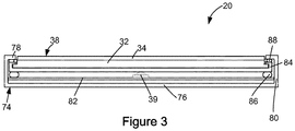
- the portable electronic device 20 includes a housing 74 that houses the internal components that are shown in Figure 1 and frames the touch screen display 38 such that the touch screen display 38 is exposed for user-interaction therewith when the portable electronic device 20 is in use.
- the housing 74 includes a back 76, a frame 78, which frames the touch screen display 38, sidewalls 80 that extend between and generally perpendicular to the back 76 and the frame 78, and a base 82 that is spaced from and generally parallel to the back 76.
- the base 82 can be any suitable base and can include, for example, a printed circuit board or flex circuit board.
- the back 76 includes a plate (not shown) that is releasably attached for insertion and removal of, for example, the battery 58 and the SIM/RUIM card 52 described above. It will be appreciated that the back 76, the sidewalls 80 and the frame 78 can be injection molded, for example.
- the frame 78 is generally rectangular with rounded corners although other shapes are possible.
- the display 32 and the overlay 34 can be supported on a support tray 84 of suitable material such as magnesium for providing mechanical support to the display 32 and overlay 34.
- the display 32 and overlay 34 are biased away from the base 82, toward the frame 78 by biasing elements 86 such as gel pads between the support tray 84 and the base 82.
- Compliant spacers 88 which can also be in the form of gel pads for example, are located between an upper portion of the support tray 84 and the frame 78.
- the touch screen display 38 is moveable within the housing 74 as the touch screen display 38 can be moved toward the base 82, thereby compressing the biasing elements 86.
- the touch screen display 38 can also be pivoted within the housing 74 with one side of the touch screen display 38 moving toward the base 82, thereby compressing the biasing elements 86 on the same side of the touch screen display 38 that moves toward the base 82.
- the switch 39 is supported on one side of the base 82 which can be printed circuit board while the opposing side provides mechanical support and electrical connection for other components (not shown) of the portable electronic device 20.
- the switch 39 can be located between the base 82 and the support tray 84.
- the switch 39 which can be a mechanical dome-type switch, for example, can be located in any suitable position such that displacement of the touch screen display 38 resulting from a user pressing the touch screen display 38 with sufficient force to overcome the bias and to overcome the actuation force for the switch 39, depresses and actuates the switch 39.
- the switch 39 is in contact with the support tray 84.
- depression of the touch screen display 38 by user application of a force thereto causes actuation of the switch 39, thereby providing the user with a positive tactile quality during user interaction with the user interface of the portable electronic device 20.
- the switch 39 is not actuated in the rest position shown in Figure 3 , absent applied force by the user. It will be appreciated that the switch 39 can be actuated by pressing anywhere on the touch screen display 38 to cause movement of the touch screen display 38 in the form of movement parallel with the base 82 or pivoting of one side of the touch screen display 38 toward the base 82.
- the switch 39 is connected to the processor 22 and can be used for further input to the processor when actuated. Although a single switch is shown any suitable number of switches can be used.
- the touch screen display 38 includes a list of messages 96 sent from the portable electronic device 20 and received at the message application 64 (shown in Figure 1 ).
- the list of messages 96 can include any suitable message types such as email messages, Short Message Service (SMS) messages, Multimedia Messaging Service (MMS) messages, Personal Identification Number (PIN messages), and any other suitable message types as well as any combination of message types.
- SMS Short Message Service
- MMS Multimedia Messaging Service
- PIN messages Personal Identification Number
- the list is in time and date order and includes a date field 98 under which all messages sent and received on the date indicated in the date field 98 are listed.
- Each message in the list of messages 96 sent and received includes a number of fields for identification.
- these fields can include, for example, a message type field 102, a timestamp field 104, a correspondent field 106, and a subject field 108. It will be appreciated that other suitable information fields are possible as further suitable fields can be included in the list of messages 96 or suitable fields can be excluded from the list of messages 96. Regardless of the fields included, the list of messages can be provided in the message application 64, for example, upon execution of the message application 64 resulting from receipt of a user-selection of, for example, the message application 64 from a menu list of selectable applications.
- the list of messages 96 is provided in one portion of the graphical user interface while a banner 110 is located above the list of messages 96 in the orientation shown in Figure 2 .
- a button bar 112 for example, is provided below the list of messages 96 for opening, closing, deleting, or navigating between messages 96.
- the touch screen display 38 can be any suitable touch screen display such as a capacitive touch screen display, resistive touch screen display or any other suitable touch screen display.
- the touch screen display is a capacitive touch screen display 38 and includes the display 32 and the touch-sensitive overlay 34, in the form of a capacitive touch-sensitive overlay 34.
- the capacitive touch-sensitive overlay 34 includes a number of layers in a stack and is fixed to the display 32 via a suitable optically clear adhesive.
- the layers can include, for example a substrate fixed to the LCD display 32 by a suitable adhesive, a ground shield layer, a barrier layer, a pair of capacitive touch sensor layers separated by a substrate or other barrier layer, and a cover layer fixed to the second capacitive touch sensor layer by a suitable adhesive.
- the capacitive touch sensor layers can be any suitable material such as patterned indium tin oxide (ITO).
- the X and Y location of a touch event are both determined with the X location determined by a signal generated as a result of capacitive coupling with one of the touch sensor layers and the Y location determined by the signal generated as a result of capacitive coupling with the other of the touch sensor layers.
- Each of the touch-sensor layers provides a signal to the controller 36 as a result of capacitive coupling with a suitable object such as a finger of a user or a conductive object held in a bare hand of a user resulting in a change in the electric field of each of the touch sensor layers.
- the signals represent the respective X and Y location of touch values. It will be appreciated that other attributes of the user's touch on the touch screen display 38 can be determined. For example, the size and the shape of the touch on the touch screen display 38 can be determined in addition to the location (X and Y values) based on the signals received at the controller 36 from the touch sensor layers.
- a user's touch on the touch screen display 38 is determined by determining the X and Y location of touch and user-selected input is determined based on the X and Y location of touch and the application executed by the processor 22.
- the application provides the list of messages 96 and each message is selectable for opening for viewing content.
- the method of controlling the portable electronic device 20 having the touch screen display 38 includes providing a graphical user interface on the touch screen display 38, detecting a touch event at a first location on the touch screen display 38, providing a navigation indicator in the graphical user interface in response to detecting the touch event at the first location, and in response to detecting movement of the touch event from the first location to a second location while touch contact is maintained on the touch screen display, changing the position of the navigation indicator in the graphical user interface by a distance that is greater than a distance of movement of the touch event on the touch screen display, a direction of change of position based on a direction of movement of the touch event.
- a graphical user interface is displayed on the display 32 and includes user-selectable features such as a list of messages, a list of contacts, a list of calendar events, thumbnail images, text or any other suitable feature or features (step 200).
- the graphical user interface can be provided in any suitable application, such as the message application, 64 or any other suitable application.
- a touch event is detected upon user touching of the touch screen display 38.
- Such a touch event can be determined upon a user touch at the touch screen display 38 for selection of, for example, a feature or features, such as a message, text, or other feature.
- the processor 22 awaits detection of a touch event and, as shown if no touch event is detected, the touch screen display 38 is continually monitored for a touch event. Signals are sent from the touch-sensitive overlay 34 to the controller 36 when a touch event, such as a finger touching the touch screen display, is detected. Thus, the touch event is detected and the X and Y location of the touch are determined (step 202).
- a navigation indicator such as a cursor or highlighting of a feature on or proximal the location of touch is rendered (step 204).
- the navigation indicator can be rendered at the point of contact of the user's finger with the touch-sensitive overlay 34 or can be rendered near the point of contact based on a predetermined offset, for example, to compensate for a difference between an actual location of touch and a target location.
- a predetermined offset for example, can be determined based on prior calibration of the actual location of touch and a target on the touch screen display 38.
- the navigation indicator is rendered at a location based on the location of touch.
- step 206 it is determined if there is a change in the location of touch (step 206) during the touch event.
- the X and Y location of touch is determined and compared to the previously determined X and Y location, and any change in the X and Y location is resolved. If there is no change in the X and Y location of the touch, or a change that is below a minimum threshold, the process proceeds to step 212 where it is determined if a confirmation of selection is received (step 206). The location of the touch is thereby monitored to determine any changes during the touch event.
- the distance of change is determined based on the difference between the previously determined X and Y location and the new X and Y location of touch.
- the direction of change is also determined based on the same X and Y values (step 208).
- the navigation indicator is then moved relative to the graphical user interface (GUI) by, for example, scrolling highlighting through a list of features or moving a cursor through text (step 210).
- the navigation indicator is moved a distance in relation to the graphical user interface that is greater than the distance of movement of the touch event on the touch screen display 38 as determined at step 208 and the direction of movement is dependent on the direction of movement of the location of touch.
- a cursor may move in the direction of the movement of the location of touch at a distance greater than the distance traveled by the user's finger during the touch event.
- highlighting may move generally in one of two directions to scroll through a list based on a component of the direction of change of location of touch.
- highlighting may move in one of four directions through icons based on components of the direction of change of the location of touch.
- step 212 it is determined if confirmation of selection is received in the form of a signal from the switch 39 resulting from depression of the touch screen display 38 with sufficient force to cause movement of the touch screen display 39 in the form of pivoting, against the bias of the touch screen display 39 and against the actuation force of the switch 39, to thereby actuate the switch 39 (step 212). Absent actuation of the switch 39 caused by depression of the touch screen display 38, the process proceeds to step 216 where it is determined if the touch event has ended. If the user lifts his or her finger from the touch screen display 39, the end of the touch contact is detected and the process ends (step 218).
- step 206 a further change in the location of touch can be detected. If the switch 39 is actuated, however, the process proceeds to step 214 where a function associated with the location of the navigation indicator at the time of release of the switch 39 and therefore at the time the signal is sent from the switch 39 to the processor 22, is performed. The function performed is therefore dependent on the location of the navigation indicator at the time the switch 39 is released and on the application and graphical user interface in which the navigation indicator is provided.
- the associated function can be, for example, selection of a feature from a list to display further details, selection of a thumbnail image for display, selection of a location within text for entry or deletion of characters or any other suitable function.
- a new touch event can be detected at step 202 after the prior touch event has ended at step 218.
- some of the steps and substeps may be excluded.
- a ratio of distance of movement of the touch event to the distance of movement of the navigation indicator within the GUI can differ.
- the distance of movement of the navigation indicator can be based on a fixed multiple of the distance of movement of the location of touch, can be user-selectable, or can be variable.
- the ratio of distance of movement of the touch event to the distance of movement of the navigation indicator within the GUI can be dependent on the speed of movement of the location of touch.
- the speed of movement of the location of touch is determined and the ratio of distance of movement of the location of touch to the distance of movement of the navigation indicator within the GUI changes with speed of movement. For example, a faster movement of the location of touch can result in a greater distance of movement of the navigation indicator within the GUI.
- the ratio of distance of movement of the location of touch to the distance of movement of the navigation indicator within the GUI can be dependent on the distance of the navigation indicator from the location of touch. For example, the ratio can decrease with increased distance of the navigation indicator from the location of touch.
- Figure 4 shows front views of the portable electronic device 20 illustrating an example of a GUI.
- the touch screen display 38 is a capacitive touch screen display 38 as described above.
- the GUI in the present example provides the list of user-selectable features in the form of messages and each message in the list of messages 96 can be selected for opening for viewing content, for example.
- a touch event is detected upon user touching of the touch screen display 38.
- signals are sent from the touch-sensitive overlay 34 to the controller 36 and the X and Y location of the touch are determined (step 202).
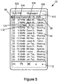
- the location of touch is determined to be at one of the messages in the list of messages 96.
- the location of touch is determined to be at the location indicated by the numeral 118 in Figure 5 .
- the navigation indicator in the form of highlighting is rendered (step 204). The highlighting is rendered at the message 120 in the list of messages 96 at which the location of touch is determined on the touch screen display 38.
- step 206 it is determined if there is a change in the location of touch.
- the location of touch has changed from the position illustrated in Figure 5 (and shown in ghost outline in Figure 6 ) to the second location of touch 122 shown in Figure 6 while touch contact is maintained with the touch screen display 38.
- the X and Y location of touch is determined and compared to the previously determined X and Y location and the change in the X and Y location is determined.
- there is a change in the Y location of the touch as indicated generally by the arrow 124.
- the location of the touch is thereby monitored to determine any changes during the touch event.
- the distance of change is determined based on the difference between the X and Y location previously determined and the new X and Y location of touch.
- the direction of change is also determined based on the same X and Y values (step 208).
- the highlighting is then moved relative the graphical user interface (GUI) by, for example, scrolling highlighting through the list of messages 96 (step 210). As shown in Figure 6 , the highlighting is moved to the message indicated by the numeral 126. The message 126 is not the message at which the location of touch moved to.
- the message 126 that the highlighting moved to is located a greater distance from the first message highlighted 120 (shown in Figure 5 ) within the GUI than the distance of the movement of the touch event on the touch screen display 38 from the first location of touch 118 ( Figure 5 ) to the second location of touch 122.
- the highlighting is moved twice the distance in the graphical user interface as the location of touch moves on the touch screen display 38.
- the navigation indicator is moved within the portion of the graphical user interface that includes the list of messages 96.
- step 212 confirmation of selection is not received at step 212 and it is determined at step 216 that the touch event has not ended. Therefore the process returns to step 206 and a further change in the location of touch can be detected.
- step 206 it is determined if there is a change in the location of touch (step 206).
- the location of touch has changed from the position illustrated in Figure 6 (and shown in ghost outline in Figure 7 ) to the further location of touch 128 shown in Figure 7 while touch contact is maintained with the touch screen display 38.
- the X and Y location of touch is determined and compared to the previously determined X and Y location from step 206 described above with reference to Figure 6 and the change in the X and Y location is determined.
- there is a change in the Y location of the touch as indicated generally by the arrow 130. The location of the touch is thereby monitored to determine any changes during the touch event.
- the distance of change is determined based on the difference between the X and Y location determined previously and the new X and Y location of touch.
- the direction of change is also determined based on the same X and Y values (step 208).
- the highlighting is then moved relative the graphical user interface (GUI) by scrolling the highlighting through the list of messages 96 (step 210). As shown in Figure 7 , the highlighting is moved to the message indicated by the numeral 132. As indicated, the highlighting moves within the GUI about twice the distance of movement of the location of touch on the touch screen display 38 in the present example.
- the highlighting moves generally in the downward direction in the GUI from the location shown in Figure 6 to the location shown in Figure 7 .
- the highlighting reaches an edge 133 of the portion of the GUI that includes the list of messages 96 rendered in Figure 6 in the present example, therefore highlighting the final message in the list.
- the list of messages scrolls upwardly while the highlighting continues to highlight the message adjacent the edge 133, thereby continuing relative movement of the highlighting within the GUI.
- the relative location within the list of messages in the GUI continues to change with continued movement of the location of touch.
- the navigation indicator is thereby moved within the portion of the graphical user interface that includes the list of messages 96.
- step 212 confirmation of selection is not received at step 212 and the user maintains touch contact with the touch screen display 38, therefore not ending the touch event (step 216).
- step 216 confirmation of selection is not received at step 212 and the user maintains touch contact with the touch screen display 38, therefore not ending the touch event (step 216).
- the process again returns to step 206 and a further change in the location of touch can be detected.
- step 206 it is determined that there is a change in the location of touch (step 206).
- the location of touch has changed from the position illustrated in Figure 7 to the further location of touch 134 shown in Figure 8 while touch contact is maintained with the touch screen display 38.
- the X and Y location of touch is determined and compared to the previously determined X and Y location from step 206 described above with reference to Figure 7 and the change in the X and Y location is determined.
- there is a change in the Y location of the touch as indicated generally by the arrow 136.
- the location of the touch is thereby monitored to determine any changes during the touch event.
- the distance of change is determined based on the difference between the X and Y location determined previously and the new X and Y location of touch.
- the direction of change is also determined based on the same X and Y values (step 208).
- the highlighting is then moved relative the graphical user interface (GUI) by scrolling the highlighting through the list of messages 96 (step 210).
- GUI graphical user interface
- the highlighting is moved to the message indicated by the numeral 138.
- the highlighting moves within the GUI about twice the distance of movement of the location of touch on the touch screen display 38. With the movement of the location of touch in the generally upward direction in the orientation shown in Figures 7 and 8 , the highlighting moves generally in the upward direction in the GUI from the location shown in Figure 7 to the location shown in Figure 8 .
- the switch 39 is actuated as a result of depression of the touch screen display 38 with sufficient force to cause movement of the touch screen display 39 in the form of pivoting, against the bias of the touch screen display and against the actuation force of the switch 39, thereby confirming selection.
- This actuation is detected (step 212) and the message highlighted at the time of release of the switch 39 is opened to display message details (step 214).
- the navigation indicator is highlighting in a list of messages.
- the present disclosure is not limited to highlighting as other navigation indicators are possible including, for example, a cursor, a pointer or any other suitable navigation indicator.
- the present disclosure is not limited to a list of messages as the graphical user interface can be any suitable graphical user interface such as other lists, icons, or text.
- Figures 9 and 10 show front views of the portable electronic device 20 illustrating a further example of a GUI.
- the GUI in the present example provides text.
- the text can be text of a message for sending from the portable electronic device 20.
- a touch event is detected upon user touching of the touch screen display 38.
- signals are sent from the touch-sensitive overlay 34 to the controller 36 and the X and Y location of the touch are determined (step 202).
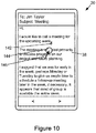
- the location of touch is determined to be at a location within the text as indicated by the numeral 140 in Figure 9 .
- the navigation indicator in the form of a pointer 142 is rendered (step 204).
- the pointer 142 is rendered in the text at the location at which the touch is determined on the touch screen display 38. It will be appreciated that the pointer 142 is initially located under the finger of the user in Figure 9 .
- step 206 it is determined if there is a change in the location of touch.
- the location of touch has changed from the position illustrated in Figure 9 to the second location of touch 144 shown in Figure 10 while touch contact is maintained with the touch screen display 38.
- the X and Y location of touch is determined and compared to the previously determined X and Y location and the change in the X and Y location is determined.
- there is a change in the Y location of the touch as indicated generally by the arrow 146.
- the location of the touch is thereby monitored to determine any changes during the touch event.
- the distance of change is determined based on the difference between the previously determined X and Y location of touch and the new X and Y location of touch.
- the direction of change is also determined based on the same X and Y values (step 208).
- the pointer 142 is then moved relative to the graphical user interface (GUI) in the text (step 210). As shown in Figure 10 , the pointer 142 is moved in the same direction as the direction of the movement of the touch.
- GUI graphical user interface
- the pointer 142 is moved within the GUI to a location that is a greater distance from the previous location of the pointer 142 (shown in Figure 9 ) than the distance on the touch screen display 38 from the first location of touch 140 ( Figure 9 ) to the second location of touch 144.
- confirmation of selection is received at step 212 as the switch 39 is actuated as described above and a function is performed.
- the function performed is to provide a cursor at the location of the pointer 144 in the text, for example, for insertion of further text (step 214).
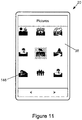
- Figure 11 shows an example of a GUI including thumbnail pictures 148.
- the method as described with reference to Figure 4 can also be used for selection of one of the thumbnail pictures 148, for example.
- the steps as described above are therefore carried out for selection of one of the thumbnail pictures 148. These steps are described herein with reference to other examples and therefore these steps need not be further described in relation to Figure 11 .
- Steps 300 to 316 are similar to steps 200 to 216 of Figure 4 and therefore these steps are not described again herein. If it is determined that the touch event has ended at step 316, however the process proceeds to step 320 where it is determined if the navigation indicator is adjacent an edge within the GUI. If the navigation indicator is not adjacent the edge of the portion of the GUI, the process ends at step 318.
- the edge can be an edge of a portion of the GUI including a list of messages, contacts, calendar events, text, thumbnail images, or any other suitable features. For example, in the GUI shown in Figure 7 , the highlighting is adjacent the edge of the portion of the GUI that includes the list of messages.
- the features can continue to scroll after the end of the touch event (step 322) if it is determined that the navigation indicator is adjacent the edge.
- the highlighting reaches an edge133 of the portion of the GUI that includes the list of messages 96
- the list of messages scrolls upwardly while the highlighting continues to highlight the message adjacent the edge 133, thereby continuing relative movement of the highlighting within the GUI as described with reference to Figure 4 .
- the scrolling can continue even when the user ends the touch event by, for example, lifting the finger from the touch screen display 38.
- the speed of scrolling at step 322 can be fixed at a suitable speed or can be dependent on other features.
- the speed of scrolling can be dependent on the speed of change in touch location prior to the end of the touch event, therefore requiring a determination of the speed of change prior to the end of the touch event.
- Scrolling can continue until the end of the list, text or thumbnails is reached or can continue for a suitable length of time or number of features.
- scrolling can continue for a predefined number of features, or for a number of features based on the speed of scrolling prior to ending the touch event. Scrolling can end when a further touch event is detected.
Claims (15)
- Verfahren zur Steuerung eines tragbaren elektronischen Geräts (20) mit einer Berührungsbildschirmanzeige (38), wobei das Verfahren umfasst:Bereitstellen einer grafischen Benutzeroberfläche auf der Berührungsbildschirmanzeige (38);Erfassen eines Berührungsereignisses an einer ersten Position auf der Berührungsbildschirmanzeige (38);Anzeigen eines Navigationsindikators auf der grafischen Benutzeroberfläche in Reaktion auf das Erfassen des Berührungsereignisses an der ersten Position; undin Reaktion auf das Erfassen einer Bewegung des Berührungsereignisses von der ersten Position in eine zweite Position, während der Berührungskontakt auf der Berührungsbildschirmanzeige (38) aufrechterhalten wird, Ändern einer Position des Navigationsindikators auf der grafischen Benutzeroberfläche durch Bewegen des Navigationsindikators bezogen auf mindestens einen Abschnitt der grafischen Benutzeroberfläche,wobei die Position des Navigationsindikators um einen Abstand geändert wird, der größer ist als ein Abstand der Bewegung des Berührungsereignisses, sodass sich der Navigationsindikator von der Berührung wegbewegt, undwobei eine Richtung der Änderung der Position des Navigationsindikators auf einer Richtung der Bewegung des Berührungsereignisses auf der Berührungsbildschirmanzeige (38) basiert und wobei das Aufbringen einer Kraft durch den Benutzer die Betätigung eines Schalters (39) verursacht, wodurch dem Benutzer eine positive taktile Qualität während der Benutzerinteraktion mit der Benutzeroberfläche des tragbaren elektronischen Geräts (20) bereitgestellt wird.
- Verfahren nach Anspruch 1, wobei sich der Navigationsindikator von der Berührung wegbewegt, bis der Navigationsindikator einen Rand des Abschnitts erreicht.
- Verfahren nach Anspruch 1, wobei das Bewegen des Navigationsindikators bezogen auf den Abschnitt der grafischen Benutzeroberfläche das Scrollen des Abschnitts der grafischen Benutzeroberfläche umfasst, wenn der Navigationsindikator einen Rand des Abschnitts erreicht.
- Verfahren nach einem der Ansprüche 1 bis 3, umfassend das Auswählen eines Merkmals an dem Navigationsindikator in Reaktion auf den Empfang einer Eingabe von einem Schalter (39), der infolge der Bewegung der Berührungsbildschirmanzeige (38) bezogen auf einen Rest des tragbaren elektronischen Geräts (20) betätigt wird.
- Verfahren nach Anspruch 4, umfassend das Durchführen einer Funktion in Reaktion auf den Empfang der Eingabe.
- Verfahren nach einem vorhergehenden Anspruch, wobei das Verhältnis festgelegt ist und der Abstand der Änderung der Position des Navigationsindikators auf der grafischen Benutzeroberfläche auf einem festen Vielfachen des Abstands der Bewegung der Berührung basiert.
- Verfahren nach einem der Ansprüche 1 bis 5, wobei das Verhältnis ein variables Verhältnis von dem Abstand der Bewegung des Berührungsereignisses zu dem Abstand der Änderung der Position des Navigationsindikators ist.
- Verfahren nach Anspruch 7, wobei das variable Verhältnis von einem Abstand des Navigationsindikators von dem Berührungsereignis abhängt.
- Verfahren nach Anspruch 7, umfassend das Bestimmen einer Geschwindigkeit der Bewegung des Berührungsereignisses von der ersten Position in eine zweite Position in Reaktion das Erfassen der Bewegung des Berührungsereignisses von der ersten Position in eine zweite Position, während der Berührungskontakt auf der Berührungsbildschirmanzeige (38) aufrechterhalten wird.
- Verfahren nach Anspruch 9, wobei das variable Verhältnis von der Bewegungsgeschwindigkeit des Berührungsereignisses abhängt.
- Verfahren nach Anspruch 9, umfassend das Fortsetzen des Bewegens des Navigationsindikators bezogen auf mindestens einen Abschnitt der grafischen Benutzeroberfläche nach Ende des Berührungsereignisses.
- Verfahren nach Anspruch 11, wobei eine Geschwindigkeit der Bewegung des Navigationsindikators bezogen auf mindestens den Abschnitt der grafischen Benutzeroberfläche von einer Geschwindigkeit der Bewegung der Berührung vor dem Ende des Berührungsereignisses abhängt.
- Verfahren nach einem vorhergehenden Anspruch, wobei der Navigationsindikator einen Cursor oder eine Markierung umfasst.
- Tragbares elektronisches Gerät (20), umfassend:eine Berührungsbildschirmanzeige (38); undeinen Prozessor (22), der mit der Berührungsbildschirmanzeige (38) gekoppelt ist, und eine Speichereinrichtung mit darin gespeichertem computerlesbarem Programmcode; der computerlesbare Code ist durch den Prozessor ausführbar, um das Verfahren nach einem der Ansprüche 1 bis 13 durchzuführen.
- Computerlesbares Medium, das computerlesbare Anweisungen darin enthält, die von einem Prozessor (22) eines tragbaren elektronischen Geräts (20) ausgeführt werden können, um die Schritte des Verfahrens nach einem der Ansprüche 1 bis 13 auszuführen.
Priority Applications (1)
| Application Number | Priority Date | Filing Date | Title |
|---|---|---|---|
| EP12193801.3A EP2579143B1 (de) | 2008-12-01 | 2008-12-01 | Tragbare elektronische Vorrichtung und Steuerungsverfahren dafür |
Applications Claiming Priority (2)
| Application Number | Priority Date | Filing Date | Title |
|---|---|---|---|
| EP08170345.6A EP2192479B1 (de) | 2008-12-01 | 2008-12-01 | Tragbare elektronische Vorrichtung und Steuerverfahren dafür |
| EP12193801.3A EP2579143B1 (de) | 2008-12-01 | 2008-12-01 | Tragbare elektronische Vorrichtung und Steuerungsverfahren dafür |
Related Parent Applications (3)
| Application Number | Title | Priority Date | Filing Date |
|---|---|---|---|
| EP08170345.6A Division-Into EP2192479B1 (de) | 2008-12-01 | 2008-12-01 | Tragbare elektronische Vorrichtung und Steuerverfahren dafür |
| EP08170345.6A Division EP2192479B1 (de) | 2008-12-01 | 2008-12-01 | Tragbare elektronische Vorrichtung und Steuerverfahren dafür |
| EP08170345.6 Division | 2008-12-01 |
Publications (2)
| Publication Number | Publication Date |
|---|---|
| EP2579143A1 EP2579143A1 (de) | 2013-04-10 |
| EP2579143B1 true EP2579143B1 (de) | 2019-09-18 |
Family
ID=40513966
Family Applications (2)
| Application Number | Title | Priority Date | Filing Date |
|---|---|---|---|
| EP08170345.6A Active EP2192479B1 (de) | 2008-12-01 | 2008-12-01 | Tragbare elektronische Vorrichtung und Steuerverfahren dafür |
| EP12193801.3A Active EP2579143B1 (de) | 2008-12-01 | 2008-12-01 | Tragbare elektronische Vorrichtung und Steuerungsverfahren dafür |
Family Applications Before (1)
| Application Number | Title | Priority Date | Filing Date |
|---|---|---|---|
| EP08170345.6A Active EP2192479B1 (de) | 2008-12-01 | 2008-12-01 | Tragbare elektronische Vorrichtung und Steuerverfahren dafür |
Country Status (2)
| Country | Link |
|---|---|
| EP (2) | EP2192479B1 (de) |
| CA (1) | CA2686769C (de) |
Families Citing this family (9)
| Publication number | Priority date | Publication date | Assignee | Title |
|---|---|---|---|---|
| EP2407892B1 (de) * | 2010-07-14 | 2020-02-19 | BlackBerry Limited | Tragbare elektronische Vorrichtung und Kontrollverfahren dafür |
| US20120249430A1 (en) * | 2011-03-31 | 2012-10-04 | Oster David Phillip | Multi-Touch Screen Recognition of Interactive Objects, and Application Thereof |
| US9367230B2 (en) * | 2011-11-08 | 2016-06-14 | Microsoft Technology Licensing, Llc | Interaction models for indirect interaction devices |
| WO2013067618A1 (en) | 2011-11-09 | 2013-05-16 | Research In Motion Limited | Touch-sensitive display method and apparatus |
| FR3003364A1 (fr) * | 2013-03-15 | 2014-09-19 | France Telecom | Procede de traitement d'un geste compose, dispositif et terminal d'utilisateur associes |
| CN103309673B (zh) * | 2013-06-24 | 2017-03-01 | 小米科技有限责任公司 | 一种基于手势的会话处理方法、装置 |
| CN103699289B (zh) * | 2013-12-13 | 2017-01-11 | 广州华多网络科技有限公司 | 滑动操作响应方法及装置 |
| CN110658976B (zh) * | 2014-12-24 | 2021-09-14 | 联想(北京)有限公司 | 一种触控轨迹显示方法及电子设备 |
| CN106873896B (zh) * | 2017-03-01 | 2019-01-29 | 维沃移动通信有限公司 | 一种滑动操作的控制方法及移动终端 |
Citations (2)
| Publication number | Priority date | Publication date | Assignee | Title |
|---|---|---|---|---|
| US20050028112A1 (en) * | 2003-07-30 | 2005-02-03 | Canon Kabushiki Kaisha | Reduced image production method and apparatus |
| FR2898197A1 (fr) * | 2006-03-02 | 2007-09-07 | Thomas Joseph Pouit | Ecran tactile a point d'interaction distinct du point de contact |
Family Cites Families (3)
| Publication number | Priority date | Publication date | Assignee | Title |
|---|---|---|---|---|
| US7728821B2 (en) * | 2004-08-06 | 2010-06-01 | Touchtable, Inc. | Touch detecting interactive display |
| JP2007148927A (ja) * | 2005-11-29 | 2007-06-14 | Alps Electric Co Ltd | 入力装置及びこれを用いたスクロール制御方法 |
| US7786975B2 (en) * | 2005-12-23 | 2010-08-31 | Apple Inc. | Continuous scrolling list with acceleration |
-
2008
- 2008-12-01 EP EP08170345.6A patent/EP2192479B1/de active Active
- 2008-12-01 EP EP12193801.3A patent/EP2579143B1/de active Active
-
2009
- 2009-12-01 CA CA2686769A patent/CA2686769C/en active Active
Patent Citations (2)
| Publication number | Priority date | Publication date | Assignee | Title |
|---|---|---|---|---|
| US20050028112A1 (en) * | 2003-07-30 | 2005-02-03 | Canon Kabushiki Kaisha | Reduced image production method and apparatus |
| FR2898197A1 (fr) * | 2006-03-02 | 2007-09-07 | Thomas Joseph Pouit | Ecran tactile a point d'interaction distinct du point de contact |
Also Published As
| Publication number | Publication date |
|---|---|
| EP2192479B1 (de) | 2018-02-28 |
| EP2579143A1 (de) | 2013-04-10 |
| CA2686769A1 (en) | 2010-06-01 |
| EP2192479A1 (de) | 2010-06-02 |
| CA2686769C (en) | 2013-05-21 |
Similar Documents
| Publication | Publication Date | Title |
|---|---|---|
| US8744530B2 (en) | Portable electronic device and method of controlling same | |
| EP2175357B1 (de) | Tragbare elektronische Vorrichtung und Steuerverfahren dafür | |
| US8619041B2 (en) | Portable electronic device and method of controlling same | |
| EP2175352A2 (de) | Tragbare elektronische Vorrichtung und Steuerverfahren dafür | |
| EP2175354A1 (de) | Tragbare elektronische Vorrichtung und Steuerverfahren dafür | |
| EP2579143B1 (de) | Tragbare elektronische Vorrichtung und Steuerungsverfahren dafür | |
| US8121652B2 (en) | Portable electronic device including touchscreen and method of controlling the portable electronic device | |
| US20100088653A1 (en) | Portable electronic device and method of controlling same | |
| US20100085314A1 (en) | Portable electronic device and method of controlling same | |
| US9043718B2 (en) | System and method for applying a text prediction algorithm to a virtual keyboard | |
| US20100085313A1 (en) | Portable electronic device and method of secondary character rendering and entry | |
| US20100110017A1 (en) | Portable electronic device and method of controlling same | |
| EP2175355A1 (de) | Tragbare elektronische Vorrichtung und Verfahren zur Wiedergabe und Eingabe sekundärer Zeichen | |
| US20100156939A1 (en) | Portable electronic device and method of controlling same | |
| CA2679142C (en) | Portable electronic device and method of controlling same | |
| EP2184669A1 (de) | Tragbare elektronische Vorrichtung und Steuerverfahren dafür | |
| EP2085865A1 (de) | Elektronische Vorrichtung und Steuerverfahren dafür | |
| CA2706055C (en) | System and method for applying a text prediction algorithm to a virtual keyboard | |
| EP2199898B1 (de) | Tragbares elektronisches Gerät, das einen Berührungsbildschirm beinhaltet, und Verfahren zur Steuerung des tragbaren elektronischen Geräts | |
| EP2199885A1 (de) | Tragbare elektronische Vorrichtung und Steuerverfahren dafür |
Legal Events
| Date | Code | Title | Description |
|---|---|---|---|
| PUAI | Public reference made under article 153(3) epc to a published international application that has entered the european phase |
Free format text: ORIGINAL CODE: 0009012 |
|
| 17P | Request for examination filed |
Effective date: 20121122 |
|
| AC | Divisional application: reference to earlier application |
Ref document number: 2192479 Country of ref document: EP Kind code of ref document: P |
|
| AK | Designated contracting states |
Kind code of ref document: A1 Designated state(s): AT BE BG CH CY CZ DE DK EE ES FI FR GB GR HR HU IE IS IT LI LT LU LV MC MT NL NO PL PT RO SE SI SK TR |
|
| AX | Request for extension of the european patent |
Extension state: AL BA MK RS |
|
| RAP1 | Party data changed (applicant data changed or rights of an application transferred) |
Owner name: BLACKBERRY LIMITED |
|
| RAP1 | Party data changed (applicant data changed or rights of an application transferred) |
Owner name: BLACKBERRY LIMITED |
|
| 17Q | First examination report despatched |
Effective date: 20151103 |
|
| STAA | Information on the status of an ep patent application or granted ep patent |
Free format text: STATUS: EXAMINATION IS IN PROGRESS |
|
| GRAP | Despatch of communication of intention to grant a patent |
Free format text: ORIGINAL CODE: EPIDOSNIGR1 |
|
| STAA | Information on the status of an ep patent application or granted ep patent |
Free format text: STATUS: GRANT OF PATENT IS INTENDED |
|
| INTG | Intention to grant announced |
Effective date: 20190418 |
|
| GRAS | Grant fee paid |
Free format text: ORIGINAL CODE: EPIDOSNIGR3 |
|
| GRAA | (expected) grant |
Free format text: ORIGINAL CODE: 0009210 |
|
| STAA | Information on the status of an ep patent application or granted ep patent |
Free format text: STATUS: THE PATENT HAS BEEN GRANTED |
|
| AC | Divisional application: reference to earlier application |
Ref document number: 2192479 Country of ref document: EP Kind code of ref document: P |
|
| AK | Designated contracting states |
Kind code of ref document: B1 Designated state(s): AT BE BG CH CY CZ DE DK EE ES FI FR GB GR HR HU IE IS IT LI LT LU LV MC MT NL NO PL PT RO SE SI SK TR |
|
| REG | Reference to a national code |
Ref country code: GB Ref legal event code: FG4D |
|
| REG | Reference to a national code |
Ref country code: CH Ref legal event code: EP |
|
| REG | Reference to a national code |
Ref country code: DE Ref legal event code: R096 Ref document number: 602008061253 Country of ref document: DE |
|
| REG | Reference to a national code |
Ref country code: AT Ref legal event code: REF Ref document number: 1182103 Country of ref document: AT Kind code of ref document: T Effective date: 20191015 |
|
| REG | Reference to a national code |
Ref country code: IE Ref legal event code: FG4D |
|
| REG | Reference to a national code |
Ref country code: NL Ref legal event code: MP Effective date: 20190918 |
|
| PG25 | Lapsed in a contracting state [announced via postgrant information from national office to epo] |
Ref country code: HR Free format text: LAPSE BECAUSE OF FAILURE TO SUBMIT A TRANSLATION OF THE DESCRIPTION OR TO PAY THE FEE WITHIN THE PRESCRIBED TIME-LIMIT Effective date: 20190918 Ref country code: SE Free format text: LAPSE BECAUSE OF FAILURE TO SUBMIT A TRANSLATION OF THE DESCRIPTION OR TO PAY THE FEE WITHIN THE PRESCRIBED TIME-LIMIT Effective date: 20190918 Ref country code: NO Free format text: LAPSE BECAUSE OF FAILURE TO SUBMIT A TRANSLATION OF THE DESCRIPTION OR TO PAY THE FEE WITHIN THE PRESCRIBED TIME-LIMIT Effective date: 20191218 Ref country code: FI Free format text: LAPSE BECAUSE OF FAILURE TO SUBMIT A TRANSLATION OF THE DESCRIPTION OR TO PAY THE FEE WITHIN THE PRESCRIBED TIME-LIMIT Effective date: 20190918 Ref country code: BG Free format text: LAPSE BECAUSE OF FAILURE TO SUBMIT A TRANSLATION OF THE DESCRIPTION OR TO PAY THE FEE WITHIN THE PRESCRIBED TIME-LIMIT Effective date: 20191218 Ref country code: LT Free format text: LAPSE BECAUSE OF FAILURE TO SUBMIT A TRANSLATION OF THE DESCRIPTION OR TO PAY THE FEE WITHIN THE PRESCRIBED TIME-LIMIT Effective date: 20190918 |
|
| REG | Reference to a national code |
Ref country code: LT Ref legal event code: MG4D |
|
| PG25 | Lapsed in a contracting state [announced via postgrant information from national office to epo] |
Ref country code: LV Free format text: LAPSE BECAUSE OF FAILURE TO SUBMIT A TRANSLATION OF THE DESCRIPTION OR TO PAY THE FEE WITHIN THE PRESCRIBED TIME-LIMIT Effective date: 20190918 Ref country code: GR Free format text: LAPSE BECAUSE OF FAILURE TO SUBMIT A TRANSLATION OF THE DESCRIPTION OR TO PAY THE FEE WITHIN THE PRESCRIBED TIME-LIMIT Effective date: 20191219 |
|
| REG | Reference to a national code |
Ref country code: AT Ref legal event code: MK05 Ref document number: 1182103 Country of ref document: AT Kind code of ref document: T Effective date: 20190918 |
|
| PG25 | Lapsed in a contracting state [announced via postgrant information from national office to epo] |
Ref country code: PT Free format text: LAPSE BECAUSE OF FAILURE TO SUBMIT A TRANSLATION OF THE DESCRIPTION OR TO PAY THE FEE WITHIN THE PRESCRIBED TIME-LIMIT Effective date: 20200120 Ref country code: NL Free format text: LAPSE BECAUSE OF FAILURE TO SUBMIT A TRANSLATION OF THE DESCRIPTION OR TO PAY THE FEE WITHIN THE PRESCRIBED TIME-LIMIT Effective date: 20190918 Ref country code: PL Free format text: LAPSE BECAUSE OF FAILURE TO SUBMIT A TRANSLATION OF THE DESCRIPTION OR TO PAY THE FEE WITHIN THE PRESCRIBED TIME-LIMIT Effective date: 20190918 Ref country code: ES Free format text: LAPSE BECAUSE OF FAILURE TO SUBMIT A TRANSLATION OF THE DESCRIPTION OR TO PAY THE FEE WITHIN THE PRESCRIBED TIME-LIMIT Effective date: 20190918 Ref country code: RO Free format text: LAPSE BECAUSE OF FAILURE TO SUBMIT A TRANSLATION OF THE DESCRIPTION OR TO PAY THE FEE WITHIN THE PRESCRIBED TIME-LIMIT Effective date: 20190918 Ref country code: IT Free format text: LAPSE BECAUSE OF FAILURE TO SUBMIT A TRANSLATION OF THE DESCRIPTION OR TO PAY THE FEE WITHIN THE PRESCRIBED TIME-LIMIT Effective date: 20190918 Ref country code: EE Free format text: LAPSE BECAUSE OF FAILURE TO SUBMIT A TRANSLATION OF THE DESCRIPTION OR TO PAY THE FEE WITHIN THE PRESCRIBED TIME-LIMIT Effective date: 20190918 Ref country code: AT Free format text: LAPSE BECAUSE OF FAILURE TO SUBMIT A TRANSLATION OF THE DESCRIPTION OR TO PAY THE FEE WITHIN THE PRESCRIBED TIME-LIMIT Effective date: 20190918 |
|
| PG25 | Lapsed in a contracting state [announced via postgrant information from national office to epo] |
Ref country code: CZ Free format text: LAPSE BECAUSE OF FAILURE TO SUBMIT A TRANSLATION OF THE DESCRIPTION OR TO PAY THE FEE WITHIN THE PRESCRIBED TIME-LIMIT Effective date: 20190918 Ref country code: IS Free format text: LAPSE BECAUSE OF FAILURE TO SUBMIT A TRANSLATION OF THE DESCRIPTION OR TO PAY THE FEE WITHIN THE PRESCRIBED TIME-LIMIT Effective date: 20200224 Ref country code: SK Free format text: LAPSE BECAUSE OF FAILURE TO SUBMIT A TRANSLATION OF THE DESCRIPTION OR TO PAY THE FEE WITHIN THE PRESCRIBED TIME-LIMIT Effective date: 20190918 |
|
| REG | Reference to a national code |
Ref country code: DE Ref legal event code: R097 Ref document number: 602008061253 Country of ref document: DE |
|
| PLBE | No opposition filed within time limit |
Free format text: ORIGINAL CODE: 0009261 |
|
| STAA | Information on the status of an ep patent application or granted ep patent |
Free format text: STATUS: NO OPPOSITION FILED WITHIN TIME LIMIT |
|
| PG2D | Information on lapse in contracting state deleted |
Ref country code: IS |
|
| PG25 | Lapsed in a contracting state [announced via postgrant information from national office to epo] |
Ref country code: DK Free format text: LAPSE BECAUSE OF FAILURE TO SUBMIT A TRANSLATION OF THE DESCRIPTION OR TO PAY THE FEE WITHIN THE PRESCRIBED TIME-LIMIT Effective date: 20190918 Ref country code: IS Free format text: LAPSE BECAUSE OF FAILURE TO SUBMIT A TRANSLATION OF THE DESCRIPTION OR TO PAY THE FEE WITHIN THE PRESCRIBED TIME-LIMIT Effective date: 20200119 |
|
| REG | Reference to a national code |
Ref country code: CH Ref legal event code: PL |
|
| 26N | No opposition filed |
Effective date: 20200619 |
|
| REG | Reference to a national code |
Ref country code: BE Ref legal event code: MM Effective date: 20191231 |
|
| PG25 | Lapsed in a contracting state [announced via postgrant information from national office to epo] |
Ref country code: SI Free format text: LAPSE BECAUSE OF FAILURE TO SUBMIT A TRANSLATION OF THE DESCRIPTION OR TO PAY THE FEE WITHIN THE PRESCRIBED TIME-LIMIT Effective date: 20190918 Ref country code: MC Free format text: LAPSE BECAUSE OF FAILURE TO SUBMIT A TRANSLATION OF THE DESCRIPTION OR TO PAY THE FEE WITHIN THE PRESCRIBED TIME-LIMIT Effective date: 20190918 |
|
| PG25 | Lapsed in a contracting state [announced via postgrant information from national office to epo] |
Ref country code: LU Free format text: LAPSE BECAUSE OF NON-PAYMENT OF DUE FEES Effective date: 20191201 Ref country code: IE Free format text: LAPSE BECAUSE OF NON-PAYMENT OF DUE FEES Effective date: 20191201 |
|
| PG25 | Lapsed in a contracting state [announced via postgrant information from national office to epo] |
Ref country code: BE Free format text: LAPSE BECAUSE OF NON-PAYMENT OF DUE FEES Effective date: 20191231 Ref country code: CH Free format text: LAPSE BECAUSE OF NON-PAYMENT OF DUE FEES Effective date: 20191231 Ref country code: LI Free format text: LAPSE BECAUSE OF NON-PAYMENT OF DUE FEES Effective date: 20191231 |
|
| PG25 | Lapsed in a contracting state [announced via postgrant information from national office to epo] |
Ref country code: CY Free format text: LAPSE BECAUSE OF FAILURE TO SUBMIT A TRANSLATION OF THE DESCRIPTION OR TO PAY THE FEE WITHIN THE PRESCRIBED TIME-LIMIT Effective date: 20190918 |
|
| PG25 | Lapsed in a contracting state [announced via postgrant information from national office to epo] |
Ref country code: MT Free format text: LAPSE BECAUSE OF FAILURE TO SUBMIT A TRANSLATION OF THE DESCRIPTION OR TO PAY THE FEE WITHIN THE PRESCRIBED TIME-LIMIT Effective date: 20190918 Ref country code: HU Free format text: LAPSE BECAUSE OF FAILURE TO SUBMIT A TRANSLATION OF THE DESCRIPTION OR TO PAY THE FEE WITHIN THE PRESCRIBED TIME-LIMIT; INVALID AB INITIO Effective date: 20081201 |
|
| PG25 | Lapsed in a contracting state [announced via postgrant information from national office to epo] |
Ref country code: TR Free format text: LAPSE BECAUSE OF FAILURE TO SUBMIT A TRANSLATION OF THE DESCRIPTION OR TO PAY THE FEE WITHIN THE PRESCRIBED TIME-LIMIT Effective date: 20190918 |
|
| PGFP | Annual fee paid to national office [announced via postgrant information from national office to epo] |
Ref country code: GB Payment date: 20231227 Year of fee payment: 16 |
|
| PGFP | Annual fee paid to national office [announced via postgrant information from national office to epo] |
Ref country code: FR Payment date: 20231227 Year of fee payment: 16 |
|
| PGFP | Annual fee paid to national office [announced via postgrant information from national office to epo] |
Ref country code: DE Payment date: 20231229 Year of fee payment: 16 |