EP2579114A2 - Verwendung eines Motorschutzsystems zur Unterstützung bei der Bestimmung von Kraftwerksmetrik - Google Patents
Verwendung eines Motorschutzsystems zur Unterstützung bei der Bestimmung von Kraftwerksmetrik Download PDFInfo
- Publication number
- EP2579114A2 EP2579114A2 EP12179955.5A EP12179955A EP2579114A2 EP 2579114 A2 EP2579114 A2 EP 2579114A2 EP 12179955 A EP12179955 A EP 12179955A EP 2579114 A2 EP2579114 A2 EP 2579114A2
- Authority
- EP
- European Patent Office
- Prior art keywords
- power plant
- motor
- processes
- sub
- driven sub
- Prior art date
- Legal status (The legal status is an assumption and is not a legal conclusion. Google has not performed a legal analysis and makes no representation as to the accuracy of the status listed.)
- Withdrawn
Links
- 238000000034 method Methods 0.000 claims abstract description 156
- 238000004458 analytical method Methods 0.000 claims description 28
- 238000005457 optimization Methods 0.000 claims description 22
- 230000006870 function Effects 0.000 claims description 17
- 238000012545 processing Methods 0.000 claims description 13
- 238000005265 energy consumption Methods 0.000 claims description 10
- 238000000638 solvent extraction Methods 0.000 claims description 8
- 238000003860 storage Methods 0.000 claims description 7
- 238000011056 performance test Methods 0.000 claims description 4
- 230000004044 response Effects 0.000 claims description 4
- 238000005192 partition Methods 0.000 abstract description 10
- 239000007789 gas Substances 0.000 description 21
- 239000000446 fuel Substances 0.000 description 15
- 238000004891 communication Methods 0.000 description 12
- 230000008569 process Effects 0.000 description 8
- 238000007726 management method Methods 0.000 description 6
- 239000007788 liquid Substances 0.000 description 4
- 238000004519 manufacturing process Methods 0.000 description 4
- VNWKTOKETHGBQD-UHFFFAOYSA-N methane Chemical compound C VNWKTOKETHGBQD-UHFFFAOYSA-N 0.000 description 4
- 238000012544 monitoring process Methods 0.000 description 4
- 238000004590 computer program Methods 0.000 description 3
- 239000010687 lubricating oil Substances 0.000 description 3
- 238000012423 maintenance Methods 0.000 description 3
- 230000001932 seasonal effect Effects 0.000 description 3
- 230000035945 sensitivity Effects 0.000 description 3
- 238000012360 testing method Methods 0.000 description 3
- 238000001816 cooling Methods 0.000 description 2
- 238000010586 diagram Methods 0.000 description 2
- 230000006872 improvement Effects 0.000 description 2
- 238000012986 modification Methods 0.000 description 2
- 230000004048 modification Effects 0.000 description 2
- 239000003345 natural gas Substances 0.000 description 2
- 230000037361 pathway Effects 0.000 description 2
- 238000010248 power generation Methods 0.000 description 2
- 239000000243 solution Substances 0.000 description 2
- XLYOFNOQVPJJNP-UHFFFAOYSA-N water Substances O XLYOFNOQVPJJNP-UHFFFAOYSA-N 0.000 description 2
- 230000033228 biological regulation Effects 0.000 description 1
- 230000005540 biological transmission Effects 0.000 description 1
- 230000015556 catabolic process Effects 0.000 description 1
- 238000006243 chemical reaction Methods 0.000 description 1
- 238000002485 combustion reaction Methods 0.000 description 1
- 239000000498 cooling water Substances 0.000 description 1
- 230000006837 decompression Effects 0.000 description 1
- 238000006731 degradation reaction Methods 0.000 description 1
- 230000005611 electricity Effects 0.000 description 1
- 238000010438 heat treatment Methods 0.000 description 1
- 230000006698 induction Effects 0.000 description 1
- 230000010365 information processing Effects 0.000 description 1
- 238000002347 injection Methods 0.000 description 1
- 239000007924 injection Substances 0.000 description 1
- 238000009434 installation Methods 0.000 description 1
- 239000000463 material Substances 0.000 description 1
- 238000005259 measurement Methods 0.000 description 1
- 230000001360 synchronised effect Effects 0.000 description 1
- 230000000007 visual effect Effects 0.000 description 1
- 238000004804 winding Methods 0.000 description 1
Images


Classifications
-
- G—PHYSICS
- G05—CONTROLLING; REGULATING
- G05B—CONTROL OR REGULATING SYSTEMS IN GENERAL; FUNCTIONAL ELEMENTS OF SUCH SYSTEMS; MONITORING OR TESTING ARRANGEMENTS FOR SUCH SYSTEMS OR ELEMENTS
- G05B23/00—Testing or monitoring of control systems or parts thereof
- G05B23/02—Electric testing or monitoring
- G05B23/0205—Electric testing or monitoring by means of a monitoring system capable of detecting and responding to faults
- G05B23/0259—Electric testing or monitoring by means of a monitoring system capable of detecting and responding to faults characterized by the response to fault detection
- G05B23/0286—Modifications to the monitored process, e.g. stopping operation or adapting control
- G05B23/0294—Optimizing process, e.g. process efficiency, product quality
-
- G—PHYSICS
- G05—CONTROLLING; REGULATING
- G05B—CONTROL OR REGULATING SYSTEMS IN GENERAL; FUNCTIONAL ELEMENTS OF SUCH SYSTEMS; MONITORING OR TESTING ARRANGEMENTS FOR SUCH SYSTEMS OR ELEMENTS
- G05B2219/00—Program-control systems
- G05B2219/30—Nc systems
- G05B2219/32—Operator till task planning
- G05B2219/32015—Optimize, process management, optimize production line
Definitions
- the present invention relates generally to motor protection systems and more particularly to using motor protection measurements generated from a motor protection system to assist in determining power plant metrics.
- Power plant optimization software packages are often used to monitor, maintain, schedule and optimize performance of a power plant. These power plant optimization software packages provide a great deal of information. However, there are gaps of information with respect to providing an understanding of the operation of a power plant that are not readily provided by these software packages. For example, typical power plant optimization software packages generally do not generate information (e.g., power profiles) that provides an understanding of the various sub-processes or auxiliary systems that operate within a power plant. As a result, plant operators have to set-up various types of equipment (e.g., potential transformers, current transformers and wattmeters) to the sub-processes if it is desired to obtain more information than what is provided by these power plant optimization software application packages. Setting up this equipment to the sub-processes can be complicated and expensive, thus making it undesirable to delve further into understanding information gaps not addressed by these power plant optimization software application packages.
- equipment e.g., potential transformers, current transformers and wattmeters
- a system comprising a power plant; a plurality of motor-driven sub-processes operating within the power plant; a plurality of motor protection systems, each coupled to one of the plurality of motor-driven sub-processes to generate a plurality of sub-process operational data therefrom; and a controller that uses the plurality of sub-process operational data generated from the plurality of motor-driven sub-processes to determine power plant metrics including net power plant output and costs each of the plurality of motor-driven sub-processes has on the overall operation of the power plant.
- a computer system comprises: at least one processing unit; memory operably associated with the at least one processing unit; and a power plant optimization application storable in memory and executable by the at least one processing unit that obtains operational data from a plurality of motor protection systems used with a plurality of motor-driven sub-processes operating within a power plant.
- the power plant optimization application is configured to perform the method comprising: determining a plurality of power plant metrics including net power plant output and costs each of the plurality of motor-driven sub-processes has on the overall operation of the power plant; partitioning the plurality of power plant metrics into one or more predetermined groupings; and generating a representation of the plurality of power plant metrics for at least one of the predetermined groupings in response to receiving a user-specified grouping selection.
- a computer-readable storage medium storing computer instructions.
- the computer instructions which when executed, enable a computer system to facilitate power plant optimization.
- the computer instructions comprise: obtaining operational data from a plurality of motor protection systems used with a plurality of motor-driven sub-processes operating within a power plant: determining a plurality of power plant metrics including net power plant output and costs each of the plurality of motor-driven sub-processes has on the overall operation of the power plant; partitioning the plurality of power plant metrics into one or more predetermined groupings; and generating a representation of the plurality of power plant metrics for at least one of the predetermined groupings in response to receiving a user-specified grouping selection.
- Various embodiments of the present invention are directed to obtaining operational information generated from motor-driven sub-processes that operate within a power plant, and using this information to determine a multitude of power plant metrics.
- motor protection systems may be used within each of the motor-driven sub-processes to obtain the operational data.
- a controller may receive the operational data from the motor protection systems and use it to determine the power plant metrics.
- the power plant metrics may include net power plant output, costs of each of the motor-driven sub-processes as applied against the overall operation of the power plant, sub-process plant output for each of the sub-processes, energy consumption of each of the sub-processes determined as a function of sub-process plant output, whether each of the sub-processes is a chargeable thermodynamic loss that can be deducted from the net power plant output, an aggregate cost of the overall operation of the power plant that is based on the costs of each of the sub-processes, and a net heat rate of the power plant determined as a function of the sub-process operational data generated from the sub-processes.
- the controller may partition the power plant metrics into one or more groupings in order to facilitate an understanding of these metrics as applied to the various aspects of power plant operation.
- the one or more groupings may include power plant standardized performance test codes, chargeable thermodynamic losses, contractual guarantees associated with the operation of the power plant, electrical assets operating within the motor-driven sub-processes that are eligible for energy credit savings programs, types of costs (e.g., fixed, variable, semi-variable) associated with the electrical assets operating within the sub-processes or loads associated with the sub-processes.
- the controller may use the operational data from the motor protection systems to perform a cost accounting analysis on the motor-driven sub-processes, a power accounting analysis of the power generated from each of the sub-processes and an energy accounting analysis of the impact of energy consumption by each of the sub-processes on the overall operation of the power plant.
- Technical advantages of the various embodiments of the present invention include improving monitoring, management, maintenance and optimization of a power plant including motor-driven sub-processes operating within the plant. Improved monitoring, management, maintenance and optimization of the power plant including its motor-driven sub-processes result in increased efficiency and productivity of the plant.
- FIG. 1 is a schematic block diagram of an example of a representation of a power plant in which a system 100 according to one embodiment of the present invention can be implemented.
- the power plant representation of FIG. 1 shows a gas turbine (GT) 105, a steam turbine (ST) 110 and a gas turbine (GT) generator 112 interspersed among various auxiliary systems (i.e., Sub-Process 1, Sub-Process 2, Sub-Process 3 and Sub-Process 4) having auxiliary machinery (electrical assets) coupled to common electrical buses.
- GT gas turbine
- ST steam turbine
- GT gas turbine
- a 115 kilovolt (kV) high yard utility power connects to a three-phase transformer (XFMR-1) that splits this voltage among a primary transformer (i.e., the top circle of XFMR-1) and two secondary transformers (i.e., the right-hand circle and left-hand circle of XFMR-1).
- XFMR-1 three-phase transformer
- secondary transformer on the right-hand side of XFMR-1 generates a 13.8 kV voltage that is provided along a voltage bus
- the secondary transformer on the left-hand side of XFMR-1 generates a 4160 V voltage that is provided along a voltage bus.
- the 13.8 kV voltage bus feeds three very large motor/compressor sets that are used in Sub-Process 1, and feeds gas turbine 105.
- one motor/compressor set that is in Sub-Process 1 is designated by an MC-001.
- the prefixes 1, 2 and 3 that precede MC-001 are used to designate that each motor/compressor set is used in one of the auxiliary systems of Sub-Process 1.
- the 13.8 kV voltage bus also feeds Sub-Process 4, which may be a self-contained process skid (e.g., a small lube oil supply skid), by a long cable via a step-down transformer (XFMR-4) with fixed taps.
- the self-contained process skid of Sub-Process 4 comprises several motor/pump sets.
- the motor/pump sets that are in Sub-Process 4 are designated by 4-MP.
- the suffixes 001A, 001B and 002 designate the motor/pump set used in Sub-Process 4.
- Sub-Process 2 as shown in FIG. 1 comprises motor/pump sets 2-MP-002, 2-MP-003 and 2-MP-004. Note that motor/pump 2-MP-004 receives 480V via a step-down transformer XFMR-2 that reduces the 4160V to the 480V.
- Sub-Process 3 is coupled to the 4160 V bus via a long 3-phase cable run.
- Sub-Process 3 is shown as comprising a multiple of motor/pump sets 3-MP-002, 3-MP-003, 3-MP-004 and 3-MP-005.
- motor/pump 3-MP-005 receives 480V via a step-down transformer XFMR-3 that reduces the 4160V to the 480V.
- FIG. 1 shows gas turbine (GT) generator 112 coupled to the grid via a generator step-down transformer GSU XFMR-1.
- the step-down transformer GSU XFMR-1 lowers the 115 kV from the grid to 18 kV as it is supplied to gas turbine (GT) generator 112.
- FIG. 1 The power plant representation illustrated in FIG. 1 is only one example of a schematic representation of a power plant and that for ease of illustrating embodiments of the present invention other components of the power plant are not illustrated herein. Moreover, those skilled in the art will recognize that typical power plants could have much more auxiliary systems or sub-processes than what is illustrated in FIG. 1 . The power plant representation of FIG. 1 is not meant to limit the scope of the various embodiments of the present invention described herein.
- a motor protection system 115 is shown coupled to each Sub-Process.
- Each motor protection system 115 protects the motors operating within the motor-driven sub-processes from failing by protecting against items that may include unbalanced loads, excessively high overcurrent faults, undervoltage conditions, overvoltage conditions, mechanical jams and load losses.
- the motors used in the motor-driven sub-processes may be industrial electric motors such as three-phase motors (e.g., induction motors and synchronous motors).
- each motor protection system 115 is capable of capturing a multitude of data from the motor-driven sub-processes. For example, each motor protection system 115 can obtain data from the motors operating within the motor-driven sub-processes such as voltage, phase voltage, frequency, current, power, VARs used to measure reactive power, etc. In addition, each motor protection system 115 can obtain data that provides a measure of other parameters of the power generation process. Also, each motor protection system 115 can generate statistical data of the motors including, for example, maximum values, minimum values, moving values of average, standard deviation, extreme ranges, etc. Furthermore, each motor protection system 115 can obtain data from the windings and bearings of the motors, as well as some of the devices (e.g., pumps, compressors) driven by these motors.
- the devices e.g., pumps, compressors
- FIG. 1 shows only one motor protection system 105 per sub-process.
- each motor in the sub-process could have its own motor protection system 105 coupled thereto protect the motor and to obtain various operational data.
- Motor protection system 115 may be any commercially available motor protection device such as a motor control center, electric meter or relay.
- a commercially available motor protection system that may be used as motor protection system 115 is a 369 Motor Management Relay sold by GE Multilin. Those skilled in the art will recognize that there are other commercially available motor protection devices that perform functions and generate information similar to the 369 Motor Management Relay.
- a controller 120 connects to each sub-process (i.e., Sub-Process 1, Sub-Process 2, Sub-Process 3, and Sub-Process 4) including the motor protection systems 115.
- controller 120 communicates to the motor-driven sub-processes and the motor protection systems 115 via a communications network 125.
- controller 120 can be used to determine a multitude of power plant metrics from the operational data. For example, controller 120 can determine the net power plant output, which is the power generated from the power plant minus the internal plant load of each of the motor-driven sub-processes that detract from the generated power.
- the sub-process plant output provides a measure of the amount of thermodynamic loss that the internal plant loads of the motor-driven sub-processes has on the power generated from the power plant.
- Controller 120 can determine the sub-process plant output metric for each of the motor-driven sub-processes (i.e., Sub-Process 1, Sub-Process 2, Sub-Process 3 and Sub-Process 4). In one embodiment, controller 120 determines the sub-process plant output as a function of energy consumption of each of the motor-driven sub-processes. Controller 120 can use the sub-process plant output for each of the motor-driven sub-processes to determine whether each sub-process is a chargeable thermodynamic loss that can be deducted from the net power plant output. Controller 120 can also use the sub-process plant output to correlate a cost that each of the motor-driven sub-processes has on the overall operation of the power plant. With all of the costs determined, controller 120 can sum up these costs in order to determine an aggregate cost of the overall operation of the power plant that is based on the costs of each of the motor-driven sub-processes.
- controller 120 can track the aggregate cost of the overall operation of the power plant to generate a contractual performance indicator that indicates whether the power plant is conforming to predetermined contractual guarantees specified for operation of the power plant. Oftentimes, sales and installations of power plants are the subject of various performance specifications memorialized in contracts between power plant manufacturers and customers that specify certain performance guarantees. In one embodiment, the performance indication determined by controller 120 can indicate whether the power plant is meeting these contractual guarantees or is not.
- the net heat rate of the power plant is the amount of heat input to an engine or thermodynamic cycle in BTU per kWh of net plant power output.
- the net plant power output can be defined as the energy provided to the grid less the amount of power consumed by the power plant illustrated in the figure to produce that energy.
- the usual and expected English system of BTU/kWh is an inverse efficiency.
- controller 120 can use the operational data generated from the motor protection systems 115 to perform other metrics that pertain to accounting analyses.
- controller 120 can use the operational data generated from the motor protection systems 115 to perform a cost accounting analysis on the motor-driven sub-processes.
- the cost accounting analysis could entail, for example, capturing the marginal cost of running a turbine on liquid fuel, and the energy consumed by the motors of the liquid fuel forwarding pumps, the fuel pump, atomizing air compressor and water injection system for NOx abatement.
- controller 120 can use the operational data generated from the motor protection systems 115 to perform a power accounting analysis of the power generated from each of the motor-driven sub-processes and an energy accounting analysis of the impact of energy consumption by each of the sub-processes on the overall operation of the power plant.
- the power accounting analysis could entail, for example, tracking power consumption from groups of motors operating to achieve a common purpose, such as a large bank of cooling fans. Many power plants just let all of their cooling fans run all of the time. In particular, by exhortation from the United States Department of Energy, there are incentives to reduce power consumption by placing controls in the fan system to turn off or turn down the speed of the fans on cool to cold days.
- controller 120 determines the above-noted power plant metrics including the various above-noted accounting analyses.
- controller 120 used in the determination of power plant metrics
- controller 120 can be used to perform additional functions.
- controller 120 can be used as a host computer that is at a remote location that performs remote monitoring and diagnostics of the motor-driven sub-processes, as well as general management of the electrical assets that form the auxiliary systems.
- controller 120 located remotely from the power plant, it is possible to configure a controller locally, or even have a controller that is specifically configured to each of the motor-driven sub-processes in the power plant.
- FIG. 2 shows a flow chart 200 illustrating the operation of generating power plant metrics from a power plant like the one depicted in FIG. 1 according to one embodiment of the present invention. As shown in FIG. 2 , flow chart 200 begins at 210 where operational data is received from the motor protection systems 115 ( FIG.
- controller 120 located about each of the motor-driven sub-processes operating within power plant 100 ( FIG. 1 ).
- controller 120 receives operational data from each of the motor protection systems 115 via communications network 125 ( FIG. 1 ), such as voltage, phase voltage, frequency, current, power, VARs, phase current, current unbalance, voltage unbalance, etc.
- controller 120 obtains information that facilitates the determination of the power plant metrics.
- allocation factors, multipliers, and cost factors are retrieved in order to determine various power plant metrics.
- the allocation factors, multipliers, and cost factors which can specified by an operator beforehand, are generally factors multiplied by the power readings that are used to convert watts into dollars.
- a natural gas compressor is sometimes used to boost the pipeline pressure up to the required value.
- the allocation of the cost of electricity consumed by the compressor motor can be dynamically allocated to the turbines running based upon their fuel consumption.
- controller 120 uses the operational data and the allocation factors, multipliers, and/or cost factors to determine the power plant metrics.
- one of the power plant metrics includes the net power plant output, which is the power generated from the power plant minus the internal plant load of each of the motor-driven sub-processes that detract from the generated power. Stated another way, the net power plant output is generated power less those "chargeable" losses in the plant that provide inputs to the air Brayton cycle for a gas turbine or the Rankine cycle for a typical steam turbine.
- Net heat rate of the power plant is another power plant metric that can be determined by controller 120.
- Q is typically defmed as the Btu/lb of fuel consumed * lbs/hour of fuel consumption
- Q is typically defined as enthalpy in Btu/lb * lbs/hour of steam flow.
- Net_Output ⁇ G Dwatts G - ⁇ L MotorPower L * Allocation L , wherein
- controller 120 can determine other power plant metrics. For instance, the sub-process plant output, which provides a measure of the amount of thermodynamic loss that the internal plant loads of each of the motor-driven sub-processes has on the power generated from the power plant can be determined.
- the sub-process plant output is a function of energy consumption of each of the motor-driven sub-processes and is typically determined by the fuel consumption of the gas turbines.
- controller 120 can use the sub-process plant output for each of the motor-driven sub-processes to determine whether each sub-process is a chargeable thermodynamic loss that can be deducted from the net power plant output.
- Controller 120 can also use the sub-process plant output to correlate a cost that each of the motor-driven sub-processes has on the overall operation of the power plant.
- the cost that a motor-driven sub-process has on the operation of the power plant is determined by its kWh energy consumption. With all of the costs determined, controller 120 can sum up these costs in order to determine an aggregate cost of the overall operation of the power plant that is based on the costs of each of the motor-driven sub-processes.
- controller 120 Another power plant metric determination that controller ( FIG. 1 ) can perform includes tracking the aggregate cost of the overall operation of the power plant with respect to an outstanding contract between a power plant manufacturer and a customer that specifies certain performance guarantees.
- controller 120 tracks the aggregate cost of the overall operation of the power plant by generating a contractual performance indicator that indicates whether the power plant is conforming to predetermined contractual guarantees. This functionality gives the ability to track part-load net output and heat rate at all times.
- controller 120 can perform other metrics for the power plant that pertain to accounting analyses.
- controller 120 can perform a cost accounting analysis on the motor-driven sub-processes operating within the power plant.
- the cost accounting analysis could entail, for variable costs, determining factors that convert power in to dollars.
- the cost accounting analysis could entail capturing the total energy consumption of devices not directly attributed to power generation, in order to help determine more accurate plant overhead costs.
- controller 120 can perform a power accounting analysis of the power generated from each of the motor-driven sub-processes and an energy accounting analysis of the impact of energy consumption by each of the sub-processes on the overall operation of the power plant.
- the power accounting analysis could entail accurately understanding each sub-process within a plant to accurately aggregate consumption, while the energy accounting analysis could entail determining results similar to the power accounting analysis.
- the ability of controller 120 to store and retrieve this information gives the user the ability to trend data as a function of plant load during a day, seasonal variations during the year, or over years to assess degradation of the equipment.
- controller 120 partitions the power plant metrics according to one or more predetermined groupings.
- the predetermined groupings may be specified by an operator or configured by controller 120 to match the particular information desired by the operator.
- one grouping of the power plant metrics can be by standardized performance test codes. For example, certain motor-driven sub-processes operating within a power plant operate according to standardize test codes such as, for example, those set by the American Society of Mechanical Engineers (ASME).
- ASME American Society of Mechanical Engineers
- the ASME uses power test codes (PTC) to test the operation of steam turbines (e.g., PTC 6), gas turbines (e.g., PTC 22), the overall plant (e.g., PTC 46), and auxiliary systems (e.g., PTC 46c).
- PTC power test codes
- Partitioning the power plant metrics by ASME PTCs is advantageous because it becomes clear to the plant operator where to make improvement in his or her equipment for efficiency and capacity improvements.
- an operator could optimize three-way valves with bypass loops used with high-pressure feedwater pumps to save pump power by proper choice of the valve and the bypass flow impedance.
- controller 120 may partition the power plant metrics according to chargeable thermodynamic losses.
- feedwater pumps for steam plant operation and liquid fuel pumps for gas turbine fuel systems are directly chargeable to the thermodynamic cycle and could be partitioned by these thermodynamic losses.
- a 2 horsepower motor running a sump pump in a control room is not a chargeable thermodynamic loss against turbine performance, and thus this might be something that is not partitioned for viewing by a plant operator.
- a plant operator would likely have an interest in the pump used by a liquid fuel pump to supply fuel to a gas turbine because the thermodynamic cycle of the turbine may be affected.
- this metric could be made readily available along with any other sub-processes that are chargeable thermodynamic losses.
- controller 120 may partition the power plant metrics according to contractual guarantees associated with operation of the power plant.
- controller 120 could generate a representation of the power plant metrics according to the various aspects of operation of a power plant that are specific to certain contractual performance guarantees.
- all of the motors in FIG. 1 could be used in a process to manufacture synthetic gas for fuel and belong to a different enterprise than the gas turbines that burn that fuel. So, for proper bookkeeping for power, energy or cost, the need to allocate becomes apparent.
- a synthetic gas facility may have a contractual guarantee to deliver an equivalent therm of natural gas at a given cost/therm.
- Embodiments of the present invention assist in the appropriate allocation of that information by economically gathering key information from motor protection system 115 (e.g., motor control centers) that has been heretofore unavailable.
- controller 120 may partition the power plant metrics according to any electrical assets operating within any of the motor-driven sub-processes that are eligible for energy credit savings programs provided by a government or state agency. For example, the U.S. Department of Energy and other agencies in other countries provide credits for equipment with an auxiliary system that attains ENERGY STAR TM savings. Therefore, controller 120 could partition metrics to provide results that focus specifically on equipment or electrical assets operating in a motor-driven sub-process that are subject to ENERGY STAR TM savings. For example, some customers want to have turndown capability on a particular water cooler unit. A unit that typically has 4 or 6 fans is too much for cool conditions. As a result, customers will typically manually control operation of the fan in cool to cold weather. By enabling remote switching of fans or converting the motors driving these fans to variable frequency drives, an annual savings can be obtained. Embodiments of the present invention could identify the motors involved and summarize watts and MWhrs consumed to show before and after savings.
- controller 120 may partition the power plant metrics according to the type of cost associated with electrical assets operating within the motor-driven sub-processes. For example, equipment used in the motor-driven sub-processes of the power plant can be classified as a fixed cost, a semi-variable cost or a variable cost. By partitioning the metrics by the type of cost (i.e., fixed, semi-variable, variable) an operator can attain a fmer understanding of how these assets affect the power and costs associated with the operation of the power plant.
- type of cost i.e., fixed, semi-variable, variable
- controller 120 may partition the power plant metrics according to the loads associated with each of the motor-driven sub-processes. Partitioning the metrics by the type of cost (i.e., fixed, semi-variable, variable) also enables an operator to attain a finer understanding of how these sub-processes affect the power and costs associated with the operation of the power plant.
- type of cost i.e., fixed, semi-variable, variable
- controller 120 can then generate a representation of the metrics at 250 for viewing.
- this includes displaying the metrics on computing unit (e.g., host computer, hand-held computing device, etc.) for viewing by an operator.
- the operator can use this information to improve the monitoring, management, maintenance and optimization of the power plant and its various auxiliary systems.
- controller 120 may display a graphical representation of the power plant metrics for at least one of the user-specified groupings at 260.
- the displaying of the graphical representation of the power plant metrics for at least one of the user-specified groupings may include trending the data embodied by the metrics over a period of time.
- a user could select to view power plant metrics for a specific grouping over a period of time.
- Controller 120 would then retrieve the metrics over this time period and use well-known trending applications to overlay this data in a format that provides a visual understanding of the metrics as it trends over time.
- the ability to overlay year over year results of the power plant metrics can be desirable in order to ascertain an understanding of the seasonal and annual trends of the data in the metrics. For example, due to the nature of gas turbine sensitivity to ambient temperature and steam turbine sensitivity to cooling water temperature, understanding seasonal and annual trends of this sensitivity will provide invaluable information on the operation of the gas turbine and steam turbine during these periods.
- each block represents a process act associated with performing these functions.
- the acts noted in the blocks may occur out of the order noted in the figure or, for example, may in fact be executed substantially concurrently or in the reverse order, depending upon the act involved. Also, one of ordinary skill in the art will recognize that additional blocks that describe the processing functions may be added.
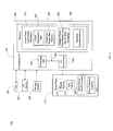
- FIG. 3 shows an example computing environment 300 in which a power plant optimization application according to one embodiment of the present invention can be implemented to perform functions including determining power plant metrics.
- computing environment 300 includes computing unit 305.
- Computing unit 305 is shown in communication with power plant 310 which is schematically represented by a steam turbine 315, a gas turbine 320, motor-driven sub-processes 325 and motor protection systems 330.
- power plant 310 which is schematically represented by a steam turbine 315, a gas turbine 320, motor-driven sub-processes 325 and motor protection systems 330.
- FIG. 3 shows that computing unit 305 is in communication with a user 335.
- User 335 may, for example, be a plant operator or another computer system.
- a plant operator may use an input/output (I/O) device 340 to interact with computing unit 305.
- I/O device 340 which may include, but is not limited to a keyboard, a display, a pointing device, etc., may couple to computing unit 305 either directly or through intervening I/O controllers.
- I/O device 340 may be any device that enables computing unit 305 to communicate with one or more other computing devices.
- Computing unit 305 includes a processing unit 345 (e.g., one or more processors), a memory component 350 (e.g., a storage hierarchy), an I/O component 355 (e.g., one or more I/O interfaces and/or devices), and a communications pathway 360 such as a bus that couples these elements.
- processing unit 345 e.g., one or more processors
- memory component 350 e.g., a storage hierarchy
- I/O component 355 e.g., one or more I/O interfaces and/or devices
- a communications pathway 360 such as a bus that couples these elements.
- computing unit 305 is in communication with user 335, I/O device 340 and a storage system 365.
- processing unit 345 may execute program code embodying power plant optimization application 370 which contains modules 375, 380, 385 and 390 that perform the functionalities described with respect to FIG. 2 .
- power plant optimization application 370 may be at least partially fixed in memory 350 and/or storage system 365.
- Computer program code for carrying out operations of embodiments of power plant optimization application 370 may be written in any combination of one or more programming languages, including but not limited to, an object oriented programming language such as Java, Smalltalk, C++ or the like and conventional procedural programming languages, such as the "C" programming language or similar programming languages.
- the program code may execute entirely on a user's computer, partly on the user's computer, as a stand-alone software package, partly on the user's computer and partly on a remote computer or entirely on the remote computer or server.
- the remote computer may be connected to the user's computer through any type of network, including a local area network (LAN) or a wide area network (WAN), or the connection may be made to an external computer (for example, through the Internet using an Internet Service Provider.
- LAN local area network
- WAN wide area network
- processing unit 345 can process data, which can result in reading and/or writing the data, such as the operational data from power plant 310 to and from memory 350, storage system 365, and/or I/O component 355 for further processing.
- Communications pathway 360 provides a communications link between each of the components in computing unit 305.
- I/O component 355 can comprise one or more human I/O devices or storage devices, which enable user 335 to interact with computing unit 305 and/or one or more communications devices.
- power plant optimization application 370 can manage a set of interfaces (e.g., graphical user interface(s), application program interface, and/or the like) that enable user 335 to interact with the application. Further, power plant optimization application 370 can manage (e.g., store, retrieve, create, manipulate, organize, present, etc.) the operational data.
- computing unit 305 can comprise one or more general purpose computing articles of manufacture capable of executing program code, such as power plant optimization application 370, installed thereon by a user 335 via a personal computer, server, handheld device, etc.
- program code may mean any collection of instructions, in any language, code or notation, that cause a computing unit having an information processing capability to perform a particular function either directly or after any combination of the following: (a) conversion to another language, code or notation; (b) reproduction in a different material form; and/or (c) decompression.
- power plant optimization application 370 can be embodied as any combination of system software and/or application software.
- power plant optimization application 370 can also be embodied as a method(s) or computer program product(s), e.g., as part of an overall control system for a power plant. Accordingly, embodiments of the present invention may take the form of an entirely hardware embodiment, an entirely software embodiment (including firmware, resident software, micro-code, etc.) or an embodiment combining software and hardware aspects that may all generally be referred to herein as a circuit, module, or system.
- the term "component” means any configuration of hardware, with or without software, which implements the functionality described in conjunction therewith using any solution
- module means program code that enables computing unit 305 to implement the functionality described in conjunction therewith using any solution.
- a module is a substantial portion of a component that implements the functionality. Regardless, it is understood that two or more components, modules, and/or systems may share some/all of their respective hardware and/or software. Further, it is understood that some of the functionality discussed herein may not be implemented or additional functionality may be included as part of computing unit 305.
- each computing device may have only a portion of power plant optimization application 370 embodied thereon (e.g., one or more modules).
- computing unit 305 and power plant optimization application 370 are only representative of various possible equivalent computing devices that may perform the process steps of the various embodiments of the present invention.
- computing unit 305 can comprise any specific purpose computing article of manufacture comprising hardware and/or computer program code for performing specific functions, any computing article of manufacture that comprises a combination of specific purpose and general purpose hardware/software, or the like.
- the program code and hardware can be created using standard programming and engineering techniques, respectively.
- computing environment 300 is only illustrative of various types of computer infrastructures for implementing the various embodiments of the present invention described herein.
- computing environment 300 may comprise two or more computing devices (e.g., a server cluster) that communicate over any type of wired and/or wireless communications link, such as a network, a shared memory, or the like, to perform the various process steps described herein.
- the communications link comprises a network
- the network may comprise any combination of one or more types of networks (e.g., the Internet, a wide area network, a local area network, a virtual private network, etc.).
Landscapes
- Engineering & Computer Science (AREA)
- Quality & Reliability (AREA)
- Physics & Mathematics (AREA)
- General Physics & Mathematics (AREA)
- Automation & Control Theory (AREA)
- Testing And Monitoring For Control Systems (AREA)
- Supply And Distribution Of Alternating Current (AREA)
- Management, Administration, Business Operations System, And Electronic Commerce (AREA)
- Control Of Electric Motors In General (AREA)
Applications Claiming Priority (1)
| Application Number | Priority Date | Filing Date | Title |
|---|---|---|---|
| US13/210,241 US20130042616A1 (en) | 2011-08-15 | 2011-08-15 | Use of motor protection system to assist in determining power plant metrics |
Publications (2)
| Publication Number | Publication Date |
|---|---|
| EP2579114A2 true EP2579114A2 (de) | 2013-04-10 |
| EP2579114A3 EP2579114A3 (de) | 2017-05-17 |
Family
ID=47071067
Family Applications (1)
| Application Number | Title | Priority Date | Filing Date |
|---|---|---|---|
| EP12179955.5A Withdrawn EP2579114A3 (de) | 2011-08-15 | 2012-08-09 | Verwendung eines Motorschutzsystems zur Unterstützung bei der Bestimmung von Kraftwerksmetrik |
Country Status (3)
| Country | Link |
|---|---|
| US (1) | US20130042616A1 (de) |
| EP (1) | EP2579114A3 (de) |
| CN (1) | CN102955084B (de) |
Families Citing this family (4)
| Publication number | Priority date | Publication date | Assignee | Title |
|---|---|---|---|---|
| US10281507B2 (en) | 2014-11-21 | 2019-05-07 | Kohler Co. | Generator sizing |
| USD811423S1 (en) | 2015-11-16 | 2018-02-27 | Kohler, Co. | Display screen with graphical user interface |
| USD810104S1 (en) | 2015-11-16 | 2018-02-13 | Kohler, Co. | Display screen with graphical user interface |
| US10802457B2 (en) * | 2017-10-23 | 2020-10-13 | Schneider Electric USA, Inc. | Centralized motor thermal memory management |
Citations (1)
| Publication number | Priority date | Publication date | Assignee | Title |
|---|---|---|---|---|
| EP2132607A1 (de) * | 2007-03-12 | 2009-12-16 | Emerson Process Management Power & Water Solutions, Inc. | Verwendung statistischer analysen bei der überwachung der leistung von kraftwerken |
Family Cites Families (14)
| Publication number | Priority date | Publication date | Assignee | Title |
|---|---|---|---|---|
| US5817958A (en) * | 1994-05-20 | 1998-10-06 | Hitachi, Ltd. | Plant monitoring and diagnosing method and system, as well as plant equipped with the system |
| US6144924A (en) * | 1996-05-20 | 2000-11-07 | Crane Nuclear, Inc. | Motor condition and performance analyzer |
| WO2003058788A1 (en) * | 2001-12-21 | 2003-07-17 | Caltek Corporation | Miniaturized motor overload protector |
| JP2006134022A (ja) * | 2004-11-05 | 2006-05-25 | Hitachi Ltd | 製品の販売価格・保守管理費用の設定評価支援装置、及び製品の販売価格・保守管理費用の設定評価支援方法 |
| US7584024B2 (en) * | 2005-02-08 | 2009-09-01 | Pegasus Technologies, Inc. | Method and apparatus for optimizing operation of a power generating plant using artificial intelligence techniques |
| WO2008011427A2 (en) * | 2006-07-17 | 2008-01-24 | Syntha Corporation | Calculating and predicting performance of power generating unit |
| CN101893877A (zh) * | 2009-05-20 | 2010-11-24 | 中国国电集团公司九江发电厂 | 一种发电厂基于能耗分析的优化运行方法及其系统 |
| CN102668295B (zh) * | 2009-10-25 | 2016-08-03 | Abb研究有限公司 | 用于改进热电厂的辅助功率系统的操作的方法和装置 |
| CA2731433C (en) * | 2010-02-09 | 2018-05-15 | Open Access Technology International, Inc. | Systems and methods for demand response and distributed energy resource management |
| US8401822B2 (en) * | 2010-04-20 | 2013-03-19 | Eaton Corporation | System, wellness circuit and method of determining wellness of a rotating electrical apparatus |
| US9063715B2 (en) * | 2010-06-10 | 2015-06-23 | Hewlett-Packard Development Company, L. P. | Management of a virtual power infrastructure |
| CN102509018B (zh) * | 2011-11-11 | 2015-03-04 | 山东电力研究院 | 电力系统设备重要性评价系统及方法 |
| CN102508925A (zh) * | 2011-11-25 | 2012-06-20 | 上海锅炉厂有限公司 | 一种电站锅炉运行性能分析系统的实现方法 |
| CN102621945B (zh) * | 2012-03-05 | 2014-03-26 | 内蒙古自治区电力科学研究院 | 基于火力发电机组最优工况的效率动态寻优运行闭环优化控制方法 |
-
2011
- 2011-08-15 US US13/210,241 patent/US20130042616A1/en not_active Abandoned
-
2012
- 2012-08-09 EP EP12179955.5A patent/EP2579114A3/de not_active Withdrawn
- 2012-08-15 CN CN201210289839.2A patent/CN102955084B/zh active Active
Patent Citations (1)
| Publication number | Priority date | Publication date | Assignee | Title |
|---|---|---|---|---|
| EP2132607A1 (de) * | 2007-03-12 | 2009-12-16 | Emerson Process Management Power & Water Solutions, Inc. | Verwendung statistischer analysen bei der überwachung der leistung von kraftwerken |
Also Published As
| Publication number | Publication date |
|---|---|
| EP2579114A3 (de) | 2017-05-17 |
| US20130042616A1 (en) | 2013-02-21 |
| CN102955084A (zh) | 2013-03-06 |
| CN102955084B (zh) | 2017-05-24 |
Similar Documents
| Publication | Publication Date | Title |
|---|---|---|
| Short et al. | Stabilization of grid frequency through dynamic demand control | |
| Khan et al. | Energy conservation in buildings: cogeneration and cogeneration coupled with thermal energy storage | |
| Zhao et al. | Optimal operation of compressor units in gas networks to provide flexibility to power systems | |
| US9335748B2 (en) | Energy management system | |
| De Bosio et al. | Thermoeconomic analysis of a Compressed Air Energy Storage (CAES) system integrated with a wind power plant in the framework of the IPEX Market | |
| Campanari et al. | Technical and tariff scenarios effect on microturbine trigenerative applications | |
| Zakeri et al. | Economy of electricity storage in the Nordic electricity market: The case for Finland | |
| Kostowski et al. | Energy and exergy recovery in a natural gas compressor station–A technical and economic analysis | |
| Mohammad Rozali et al. | A process integration approach for design of hybrid power systems with energy storage | |
| WO2004070907A2 (en) | Energy grid management method | |
| EP2579114A2 (de) | Verwendung eines Motorschutzsystems zur Unterstützung bei der Bestimmung von Kraftwerksmetrik | |
| O'Sullivan et al. | Modelling of frequency control in an island system | |
| Zunft et al. | Electricity storage with adiabatic compressed air energy storage: Results of the BMWi-project ADELE-ING | |
| Bian et al. | Frequency response in the GB power system from responsive CHPs | |
| JP2017519296A (ja) | 代替運転モードを用いた発電システムの経済的最適化 | |
| Tassenoy et al. | Assessing the influence of compressor inertia on the dynamic performance of large-scale vapor compression heat pumps for Carnot batteries | |
| Rajput et al. | Energy audit in textile industry: a study with ring frame motor | |
| Do | Performance and controls of gas turbine-driven combined cooling heating and power systems for economic dispatch | |
| Adegboye et al. | Reliability assessment of 4.2 MW single shaft typhoon gas fired turbine power generation station (2003–2008) | |
| Stathopoulos et al. | Operational strategies of wet-cycle micro gas turbines and their economic evaluation | |
| Stebbins | Are you certain you understand the economics for applying ASD systems to centrifugal loads? | |
| Almassalkhi et al. | A novel online energy management solution for energy plants | |
| Maor et al. | Cost Penalties of Near-Optimal Scheduling Control of BCHP Systems: Part I-Selection of Case Study Scenarios and Data Generation. | |
| Heideck et al. | Micro-computer control for a fuel cell test bench for residential use | |
| Coroiu | Energy efficiency evaluation method of low and medium voltage distribution systems to industrial consumers |
Legal Events
| Date | Code | Title | Description |
|---|---|---|---|
| PUAI | Public reference made under article 153(3) epc to a published international application that has entered the european phase |
Free format text: ORIGINAL CODE: 0009012 |
|
| AK | Designated contracting states |
Kind code of ref document: A2 Designated state(s): AL AT BE BG CH CY CZ DE DK EE ES FI FR GB GR HR HU IE IS IT LI LT LU LV MC MK MT NL NO PL PT RO RS SE SI SK SM TR |
|
| AX | Request for extension of the european patent |
Extension state: BA ME |
|
| PUAL | Search report despatched |
Free format text: ORIGINAL CODE: 0009013 |
|
| AK | Designated contracting states |
Kind code of ref document: A3 Designated state(s): AL AT BE BG CH CY CZ DE DK EE ES FI FR GB GR HR HU IE IS IT LI LT LU LV MC MK MT NL NO PL PT RO RS SE SI SK SM TR |
|
| AX | Request for extension of the european patent |
Extension state: BA ME |
|
| RIC1 | Information provided on ipc code assigned before grant |
Ipc: G05B 23/02 20060101AFI20170411BHEP |
|
| STAA | Information on the status of an ep patent application or granted ep patent |
Free format text: STATUS: REQUEST FOR EXAMINATION WAS MADE |
|
| 17P | Request for examination filed |
Effective date: 20171117 |
|
| RBV | Designated contracting states (corrected) |
Designated state(s): AL AT BE BG CH CY CZ DE DK EE ES FI FR GB GR HR HU IE IS IT LI LT LU LV MC MK MT NL NO PL PT RO RS SE SI SK SM TR |
|
| STAA | Information on the status of an ep patent application or granted ep patent |
Free format text: STATUS: EXAMINATION IS IN PROGRESS |
|
| 17Q | First examination report despatched |
Effective date: 20210219 |
|
| STAA | Information on the status of an ep patent application or granted ep patent |
Free format text: STATUS: THE APPLICATION IS DEEMED TO BE WITHDRAWN |
|
| 18D | Application deemed to be withdrawn |
Effective date: 20210702 |