EP2578833A2 - Exhaust gas purification apparatus of an internal combustion engine - Google Patents
Exhaust gas purification apparatus of an internal combustion engine Download PDFInfo
- Publication number
- EP2578833A2 EP2578833A2 EP20120187285 EP12187285A EP2578833A2 EP 2578833 A2 EP2578833 A2 EP 2578833A2 EP 20120187285 EP20120187285 EP 20120187285 EP 12187285 A EP12187285 A EP 12187285A EP 2578833 A2 EP2578833 A2 EP 2578833A2
- Authority
- EP
- European Patent Office
- Prior art keywords
- exhaust
- fuel ratio
- temperature
- reducing agent
- exhaust purification
- Prior art date
- Legal status (The legal status is an assumption and is not a legal conclusion. Google has not performed a legal analysis and makes no representation as to the accuracy of the status listed.)
- Granted
Links
Images


Classifications
-
- F—MECHANICAL ENGINEERING; LIGHTING; HEATING; WEAPONS; BLASTING
- F01—MACHINES OR ENGINES IN GENERAL; ENGINE PLANTS IN GENERAL; STEAM ENGINES
- F01N—GAS-FLOW SILENCERS OR EXHAUST APPARATUS FOR MACHINES OR ENGINES IN GENERAL; GAS-FLOW SILENCERS OR EXHAUST APPARATUS FOR INTERNAL-COMBUSTION ENGINES
- F01N9/00—Electrical control of exhaust gas treating apparatus
-
- F—MECHANICAL ENGINEERING; LIGHTING; HEATING; WEAPONS; BLASTING
- F01—MACHINES OR ENGINES IN GENERAL; ENGINE PLANTS IN GENERAL; STEAM ENGINES
- F01N—GAS-FLOW SILENCERS OR EXHAUST APPARATUS FOR MACHINES OR ENGINES IN GENERAL; GAS-FLOW SILENCERS OR EXHAUST APPARATUS FOR INTERNAL-COMBUSTION ENGINES
- F01N3/00—Exhaust or silencing apparatus having means for purifying, rendering innocuous, or otherwise treating exhaust
- F01N3/08—Exhaust or silencing apparatus having means for purifying, rendering innocuous, or otherwise treating exhaust for rendering innocuous
- F01N3/0807—Exhaust or silencing apparatus having means for purifying, rendering innocuous, or otherwise treating exhaust for rendering innocuous by using absorbents or adsorbents
- F01N3/0871—Exhaust or silencing apparatus having means for purifying, rendering innocuous, or otherwise treating exhaust for rendering innocuous by using absorbents or adsorbents using means for controlling, e.g. purging, the absorbents or adsorbents
- F01N3/0885—Regeneration of deteriorated absorbents or adsorbents, e.g. desulfurization of NOx traps
-
- F—MECHANICAL ENGINEERING; LIGHTING; HEATING; WEAPONS; BLASTING
- F01—MACHINES OR ENGINES IN GENERAL; ENGINE PLANTS IN GENERAL; STEAM ENGINES
- F01N—GAS-FLOW SILENCERS OR EXHAUST APPARATUS FOR MACHINES OR ENGINES IN GENERAL; GAS-FLOW SILENCERS OR EXHAUST APPARATUS FOR INTERNAL-COMBUSTION ENGINES
- F01N3/00—Exhaust or silencing apparatus having means for purifying, rendering innocuous, or otherwise treating exhaust
- F01N3/08—Exhaust or silencing apparatus having means for purifying, rendering innocuous, or otherwise treating exhaust for rendering innocuous
- F01N3/10—Exhaust or silencing apparatus having means for purifying, rendering innocuous, or otherwise treating exhaust for rendering innocuous by thermal or catalytic conversion of noxious components of exhaust
- F01N3/18—Exhaust or silencing apparatus having means for purifying, rendering innocuous, or otherwise treating exhaust for rendering innocuous by thermal or catalytic conversion of noxious components of exhaust characterised by methods of operation; Control
- F01N3/20—Exhaust or silencing apparatus having means for purifying, rendering innocuous, or otherwise treating exhaust for rendering innocuous by thermal or catalytic conversion of noxious components of exhaust characterised by methods of operation; Control specially adapted for catalytic conversion
- F01N3/2006—Periodically heating or cooling catalytic reactors, e.g. at cold starting or overheating
- F01N3/2033—Periodically heating or cooling catalytic reactors, e.g. at cold starting or overheating using a fuel burner or introducing fuel into exhaust duct
-
- F—MECHANICAL ENGINEERING; LIGHTING; HEATING; WEAPONS; BLASTING
- F01—MACHINES OR ENGINES IN GENERAL; ENGINE PLANTS IN GENERAL; STEAM ENGINES
- F01N—GAS-FLOW SILENCERS OR EXHAUST APPARATUS FOR MACHINES OR ENGINES IN GENERAL; GAS-FLOW SILENCERS OR EXHAUST APPARATUS FOR INTERNAL-COMBUSTION ENGINES
- F01N2560/00—Exhaust systems with means for detecting or measuring exhaust gas components or characteristics
- F01N2560/06—Exhaust systems with means for detecting or measuring exhaust gas components or characteristics the means being a temperature sensor
-
- F—MECHANICAL ENGINEERING; LIGHTING; HEATING; WEAPONS; BLASTING
- F01—MACHINES OR ENGINES IN GENERAL; ENGINE PLANTS IN GENERAL; STEAM ENGINES
- F01N—GAS-FLOW SILENCERS OR EXHAUST APPARATUS FOR MACHINES OR ENGINES IN GENERAL; GAS-FLOW SILENCERS OR EXHAUST APPARATUS FOR INTERNAL-COMBUSTION ENGINES
- F01N2560/00—Exhaust systems with means for detecting or measuring exhaust gas components or characteristics
- F01N2560/14—Exhaust systems with means for detecting or measuring exhaust gas components or characteristics having more than one sensor of one kind
-
- F—MECHANICAL ENGINEERING; LIGHTING; HEATING; WEAPONS; BLASTING
- F01—MACHINES OR ENGINES IN GENERAL; ENGINE PLANTS IN GENERAL; STEAM ENGINES
- F01N—GAS-FLOW SILENCERS OR EXHAUST APPARATUS FOR MACHINES OR ENGINES IN GENERAL; GAS-FLOW SILENCERS OR EXHAUST APPARATUS FOR INTERNAL-COMBUSTION ENGINES
- F01N2900/00—Details of electrical control or of the monitoring of the exhaust gas treating apparatus
- F01N2900/04—Methods of control or diagnosing
- F01N2900/0408—Methods of control or diagnosing using a feed-back loop
-
- F—MECHANICAL ENGINEERING; LIGHTING; HEATING; WEAPONS; BLASTING
- F01—MACHINES OR ENGINES IN GENERAL; ENGINE PLANTS IN GENERAL; STEAM ENGINES
- F01N—GAS-FLOW SILENCERS OR EXHAUST APPARATUS FOR MACHINES OR ENGINES IN GENERAL; GAS-FLOW SILENCERS OR EXHAUST APPARATUS FOR INTERNAL-COMBUSTION ENGINES
- F01N2900/00—Details of electrical control or of the monitoring of the exhaust gas treating apparatus
- F01N2900/06—Parameters used for exhaust control or diagnosing
- F01N2900/14—Parameters used for exhaust control or diagnosing said parameters being related to the exhaust gas
-
- F—MECHANICAL ENGINEERING; LIGHTING; HEATING; WEAPONS; BLASTING
- F01—MACHINES OR ENGINES IN GENERAL; ENGINE PLANTS IN GENERAL; STEAM ENGINES
- F01N—GAS-FLOW SILENCERS OR EXHAUST APPARATUS FOR MACHINES OR ENGINES IN GENERAL; GAS-FLOW SILENCERS OR EXHAUST APPARATUS FOR INTERNAL-COMBUSTION ENGINES
- F01N2900/00—Details of electrical control or of the monitoring of the exhaust gas treating apparatus
- F01N2900/06—Parameters used for exhaust control or diagnosing
- F01N2900/16—Parameters used for exhaust control or diagnosing said parameters being related to the exhaust apparatus, e.g. particulate filter or catalyst
- F01N2900/1602—Temperature of exhaust gas apparatus
-
- F—MECHANICAL ENGINEERING; LIGHTING; HEATING; WEAPONS; BLASTING
- F01—MACHINES OR ENGINES IN GENERAL; ENGINE PLANTS IN GENERAL; STEAM ENGINES
- F01N—GAS-FLOW SILENCERS OR EXHAUST APPARATUS FOR MACHINES OR ENGINES IN GENERAL; GAS-FLOW SILENCERS OR EXHAUST APPARATUS FOR INTERNAL-COMBUSTION ENGINES
- F01N3/00—Exhaust or silencing apparatus having means for purifying, rendering innocuous, or otherwise treating exhaust
- F01N3/02—Exhaust or silencing apparatus having means for purifying, rendering innocuous, or otherwise treating exhaust for cooling, or for removing solid constituents of, exhaust
- F01N3/021—Exhaust or silencing apparatus having means for purifying, rendering innocuous, or otherwise treating exhaust for cooling, or for removing solid constituents of, exhaust by means of filters
-
- F—MECHANICAL ENGINEERING; LIGHTING; HEATING; WEAPONS; BLASTING
- F01—MACHINES OR ENGINES IN GENERAL; ENGINE PLANTS IN GENERAL; STEAM ENGINES
- F01N—GAS-FLOW SILENCERS OR EXHAUST APPARATUS FOR MACHINES OR ENGINES IN GENERAL; GAS-FLOW SILENCERS OR EXHAUST APPARATUS FOR INTERNAL-COMBUSTION ENGINES
- F01N3/00—Exhaust or silencing apparatus having means for purifying, rendering innocuous, or otherwise treating exhaust
- F01N3/08—Exhaust or silencing apparatus having means for purifying, rendering innocuous, or otherwise treating exhaust for rendering innocuous
- F01N3/10—Exhaust or silencing apparatus having means for purifying, rendering innocuous, or otherwise treating exhaust for rendering innocuous by thermal or catalytic conversion of noxious components of exhaust
- F01N3/103—Oxidation catalysts for HC and CO only
-
- Y—GENERAL TAGGING OF NEW TECHNOLOGICAL DEVELOPMENTS; GENERAL TAGGING OF CROSS-SECTIONAL TECHNOLOGIES SPANNING OVER SEVERAL SECTIONS OF THE IPC; TECHNICAL SUBJECTS COVERED BY FORMER USPC CROSS-REFERENCE ART COLLECTIONS [XRACs] AND DIGESTS
- Y02—TECHNOLOGIES OR APPLICATIONS FOR MITIGATION OR ADAPTATION AGAINST CLIMATE CHANGE
- Y02T—CLIMATE CHANGE MITIGATION TECHNOLOGIES RELATED TO TRANSPORTATION
- Y02T10/00—Road transport of goods or passengers
- Y02T10/10—Internal combustion engine [ICE] based vehicles
- Y02T10/12—Improving ICE efficiencies
-
- Y—GENERAL TAGGING OF NEW TECHNOLOGICAL DEVELOPMENTS; GENERAL TAGGING OF CROSS-SECTIONAL TECHNOLOGIES SPANNING OVER SEVERAL SECTIONS OF THE IPC; TECHNICAL SUBJECTS COVERED BY FORMER USPC CROSS-REFERENCE ART COLLECTIONS [XRACs] AND DIGESTS
- Y02—TECHNOLOGIES OR APPLICATIONS FOR MITIGATION OR ADAPTATION AGAINST CLIMATE CHANGE
- Y02T—CLIMATE CHANGE MITIGATION TECHNOLOGIES RELATED TO TRANSPORTATION
- Y02T10/00—Road transport of goods or passengers
- Y02T10/10—Internal combustion engine [ICE] based vehicles
- Y02T10/40—Engine management systems
Definitions
- An exhaust gas discharged from an engine installed in an automobile or the like contains exhaust gas components, such as carbon monoxide (CO), hydrocarbons (HC), nitrogen oxides (NO x ), and particulate matter (PM).
- An exhaust path of the engine therefore, is provided with, for example, a three way catalyst for decomposing (for example, bringing to reduction) these substances, and a particulate filter for trapping PM.
- a seventh aspect of the present invention is the exhaust purification apparatus of an engine according to the sixth aspect, characterized in that the regeneration process execution means exercises feedforward control of the reducing agent supply means during the short lean period and, when the air-fuel ratio of the exhaust becomes richer than the predetermined air-fuel ratio and stable, exercises feedback control of the reducing agent supply means so as to bring the air-fuel ratio of the exhaust close to a target air-fuel ratio.
- An intake port 19 is formed in the cylinder head 12, and an intake pipe (intake path) 21 including an intake manifold 20 is connected to the intake port 19.
- An intake valve 22 is provided within the intake port 19, and the intake port 19 is opened and closed by the intake valve 22.
- An exhaust port 23 is formed in the cyl inder head 12 , and an exhaust pipe (exhaustpath) 25 including an exhaust manifold 24 is connected to the interior of the exhaust port 23.
- the exhaust port 23 is provided with an exhaust valve 26 and, like the intake port 19, the exhaust port 23 is opened and closed by the exhaust valve 26.
- Exhaust temperature sensors 55 are provided near the entrances of the oxidation catalyst 51, the NO x storage catalyst 52 and the DPF 53 and near an exit from the DPF 53. Furthermore, an air-fuel ratio sensor 56 for detecting the air-fuel ratio of an exhaust gas is provided near the exit of the DPF 53. In the present embodiment, as will be described later, the air-fuel ratio of the exhaust flowing out of the NO x storage catalyst 52 (hereinafter will also be referred to as "catalyst air-fuel ratio”) is detected by this air-fuel ratio sensor 56.
- the air-fuel ratio sensor 56 may be one which detects the oxygen concentration in the exhaust gas.
- the DPF 53 is, for example, a filter of a honeycomb structure formed from a ceramic material. PM trapped by the DPF 53 is oxidized (burned) by NO 2 contained in the exhaust gas, and is discharged as CO 2 . NO 2 remaining within the DPF 53 is decomposed into N 2 , and discharged.
- the A/F swing maximum value refers to a maximum value of the catalyst air-fuel ratio varying upon the intermittent injection of the fuel by the injector 54.
- the target air-fuel ratio of F/B control during the F/B period Tb3 has been set beforehand as the target value of the A/F swing maximum value.
- the injector 54 is F/B-controlled such that the A/F swing maximum value approaches the target air-fuel ratio. That is, appropriate control is effected such that the length of the lean time Tl is changed, whereby the A/F swing maximum value approaches the target air-fuel ratio.
Landscapes
- Engineering & Computer Science (AREA)
- Chemical & Material Sciences (AREA)
- Combustion & Propulsion (AREA)
- Mechanical Engineering (AREA)
- General Engineering & Computer Science (AREA)
- Chemical Kinetics & Catalysis (AREA)
- Health & Medical Sciences (AREA)
- Toxicology (AREA)
- Exhaust Gas After Treatment (AREA)
- Exhaust Gas Treatment By Means Of Catalyst (AREA)
- Processes For Solid Components From Exhaust (AREA)
Abstract
Description
- This invention relates to an exhaust purification apparatus of an engine. More specifically, the invention relates to a technology which supplies an additive to an exhaust path of an engine to regenerate an exhaust purification catalyst.
- An exhaust gas discharged from an engine installed in an automobile or the like contains exhaust gas components, such as carbon monoxide (CO), hydrocarbons (HC), nitrogen oxides (NOx), and particulate matter (PM). An exhaust path of the engine, therefore, is provided with, for example, a three way catalyst for decomposing (for example, bringing to reduction) these substances, and a particulate filter for trapping PM.
- In the case of an engine, suchas a diesel engine, whose air-fuel ratio is controlled to a lean air-fuel ratio side as compared with a stoichiometric air-fuel ratio to perform combustion in an oxidizing atmosphere, the three way catalyst cannot fully purify the nitrogen oxides (NOx) in the exhaust gas. Some exhaust paths of this type of engine, therefore, have a NOx storage catalyst, an exhaust purification catalyst, provided together with the three way catalyst. The NOx storage catalyst stores NOx contained in the exhaust when the air-fuel ratio of the exhaust is lean, but releases and reduces the stored NOx when the air-fuel ratio of the exhaust is rich. In the diesel engine or the like, the air-fuel ratio of the exhaust is normally lean, so that nitrogen oxides are stored in the NOx storage catalyst. Thus, there is need to carry out a regeneration process (NOx purge) in which a fuel (light oil) or the like, for example, is injected into the exhaust path with a predetermined timing to enrich the air-fuel ratio of the exhaust, thereby decomposing (reducing) the NOx stored in the NOx storage catalyst.
- The fuel also contains a sulfur component as a noxious component. Thus, the sulfur component reacts with oxygen to turn into sulfur oxides (SOx), which are absorbed to the NOx storage catalyst instead of NOx (S poisoning). It is necessary, therefore, to perform a regeneration process (S purge) for removing the sulfur oxides (SOx) with a predetermined timing. This regeneration process (S purge) requires that the air-fuel ratio of the exhaust be enriched as in the NOx purge, and the NOx storage catalyst be heated to a high temperature equal to or higher than a predetermined temperature.
- Various proposals have been made for the regeneration process (Spurge). An example comprises controlling a fuel injection means, which injects a fuel (reducing agent), while maintaining the NOx storage catalyst in a rich atmosphere, to repeat, alternately, periods of frequent fuel addition and periods of infrequent fuel addition, thereby heating the NOx storage catalyst to a high temperature (see, for example, Patent Document 1).
- [Patent Document 1] Japanese Patent No.
3972864 - By so repeating the periods of frequent fuel addition and the periods of infrequent fuel addition alternately during the S purge, it becomes possible to suppress the emission of HC and efficiently release SOx. If the temperature of the NOx storage catalyst falls during the S purge, however, the problem arises that the amounts of sulfur oxides released decrease accordingly. That is, the efficiency of the S purge may decline.
- When the temperature of the NOx storage catalyst falls, the amounts of emission of hydrocarbons (HC), etc. also increase. With the invention described in
Patent Document 1, when the catalyst temperature is low, discharge of hydrocarbons (HC) is suppressed by increasing the proportion of the periods of infrequent fuel addition, but in accordance with this increase, the amount of removal of sulfur oxides is also decreased (seeFig. 3 ). That is, the invention described inPatent Document 1 also poses the problem that the efficiency of S purge lowers. - The present invention has been accomplished in the light of the above-mentioned situations. It is an object of this invention to provide an exhaust purification apparatus of an engine, which can release components of an exhaust efficiently by a regeneration process.
- A first aspect of the present invention for solving the above problems is an exhaust purification apparatus of an engine, comprising: an exhaust purification catalyst provided in an exhaust path of an engine for purifying an exhaust; reducing agent supply means disposed upstream of the exhaust purification catalyst for injecting a hydrocarbon as a reducing agent into the exhaust path; temperature detection means for detecting a temperature of the exhaust purification catalyst; regeneration process execution means for performing a regeneration process which controls the reducing agent supply means to supply the reducing agent intermittently to the exhaust path so that an air-fuel ratio of the exhaust flowing out of the exhaust purification catalyst is kept rich, and renders the temperature of the exhaust purification catalyst equal to or higher than a set temperature to release exhaust components stored in the exhaust purification catalyst; and interval changing means for changing an interval between supplies of the reducing agent by the reducing agent supply means in accordance with a temperature difference between the temperature of the exhaust purification catalyst detected by the temperature detection means and the set temperature.
- A second aspect of the present invention is the exhaust purification apparatus of an engine according to the first aspect, characterized in that the interval changing means makes the interval between supplies shorter as the temperature difference becomes greater when the temperature of the exhaust purification catalyst is higher than the set temperature.
- A third aspect of the present invention is the exhaust purification apparatus of an engine according to the first or second aspect, characterized in that the interval changing means makes the interval between supplies longer as the temperature difference becomes greater when the temperature of the exhaust purification catalyst is lower than the set temperature.
- A fourth aspect of the present invention is the exhaust purification apparatus of an engine according to any one of the first to third aspects, characterized in that the regeneration process execution means implements, as the regeneration process, rich continuation periods and long lean periods alternately and repeatedly, the rich continuation periods being periods during which the reducing agent is intermittently supplied to the exhaust path so that an air-fuel ratio of the exhaust is kept rich, and the long lean periods being periods during which supply of the reducing agent to the exhaust path is stopped so that the air-fuel ratio of the exhaust becomes lean.
- A fifth aspect of the present invention is the exhaust purification apparatus of an engine according to the fourth aspect, characterized in that the regeneration process execution means performs the regeneration process in accordance with setting of a short lean period during which an interval between injections of the reducing agent by the reducing agent supply means at start of the rich continuation period of the regeneration process is shorter than a duration of injection of the reducing agent.
- A sixth aspect of the present invention is the exhaust purification apparatus of an engine according to the fifth aspect, characterized in that the regeneration process execution means terminates the short lean period when the air-fuel ratio of the exhaust becomes richer than a predetermined air-fuel ratio, which has been set beforehand, within the rich continuation period of the regeneration process.
- A seventh aspect of the present invention is the exhaust purification apparatus of an engine according to the sixth aspect, characterized in that the regeneration process execution means exercises feedforward control of the reducing agent supply means during the short lean period and, when the air-fuel ratio of the exhaust becomes richer than the predetermined air-fuel ratio and stable, exercises feedback control of the reducing agent supply means so as to bring the air-fuel ratio of the exhaust close to a target air-fuel ratio.
- An eighth aspect of the present invention is the exhaust purification apparatus of an engine according to the seventh aspect, characterized in that the target air-fuel ratio of the exhaust is set based on a maximum value of the air-fuel ratio of the exhaust which varies upon intermittent supply of the reducing agent by the reducing agent supply means.
- According to the present invention described above, a fall in the temperature of the exhaust purification catalyst is suppressed during the execution of the regeneration process. Hence, nitrogen oxides (NOx) and sulfur oxides (SOx), for example, can be discharged efficiently from the exhaust purification catalyst by the regeneration process.
-
- [
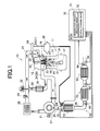
Fig. 1 ] is a schematic configurational drawing showing an engine including an exhaust purification apparatus according to an embodiment of the present invention. - [
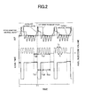
Fig. 2 ] is a graph showing changes in the catalyst air-fuel ratio and the interval between fuel injections into an exhaust pipe during S purge. - [
Fig. 3 ] is a graph showing changes in the catalyst temperature, the target air-fuel ratio, and the lean time during S purge. - [
Fig. 4 ] is a flow chart showing an example of control during S purge by the exhaust purification apparatus according to the embodiment of the present invention. - The embodiment of the present invention will now be described in detail with reference to the accompanying drawings.
- The overall configuration of an
engine 10 including an exhaust purification apparatus according to the embodiment of the present invention will be described first. Theengine 10 shown inFig. 1 is a diesel engine, in which anengine body 11 includes acylinder head 12 and acylinder block 13, and apiston 15 is accommodated within eachcylinder bore 14 of thecylinder block 13. Thepiston 15 is connected to acrankshaft 17 via a connectingrod 16. Thepiston 15, the cylinder bore 14, and thecylinder head 12 constitute acombustion chamber 18. - An
intake port 19 is formed in thecylinder head 12, and an intake pipe (intake path) 21 including anintake manifold 20 is connected to theintake port 19. Anintake valve 22 is provided within theintake port 19, and theintake port 19 is opened and closed by theintake valve 22. Anexhaust port 23 is formed in the cylinder head 12 , and an exhaust pipe (exhaustpath) 25 including anexhaust manifold 24 is connected to the interior of theexhaust port 23. Theexhaust port 23 is provided with anexhaust valve 26 and, like theintake port 19, theexhaust port 23 is opened and closed by theexhaust valve 26. - A
turbocharger 27 is provided halfway through theintake pipe 21 and theexhaust pipe 25. Anintercooler 28 is disposed in theintake pipe 21 downstream of theturbocharger 27. Athrottle valve 29 for opening and closing the intake pipe (intake path) 21 is provided in theintake pipe 21 downstream of theintercooler 28. An EGR pipe (EGR path) 30 communicating with theexhaust pipe 25 upstream of theturbocharger 27 is connected to theintake pipe 21 downstream of thethrottle valve 29. An EGRcooler 31 is provided in the EGRpipe 30, and anEGR valve 32 is provided in a junction of the EGR pipe with theintake pipe 21. - The
cylinder head 12 is provided with afuel injection valve 33 for injecting a fuel into thecombustion chamber 18 of each cylinder. Thefuel injection valve 33 is supplied with a fuel from a common-rail 34. The common-rail 34 is supplied with a fuel in a fuel tank (not shown) by asupply pump 35, and the fuel is supplied at a predetermined pressure from thesupply pump 35 to the common-rail 34 in accordance with the rotational speed of theengine body 11. In the common-rail 34, the fuel is adjusted to a predetermined fuel pressure, and a high pressure fuel controlled to the predetermined fuel pressure is supplied from the common-rail 34 to thefuel injection valve 33. - In the
exhaust pipe 25 downstream of theturbocharger 27, a diesel oxidation catalyst (will hereinafter be referred to simply as an oxidation catalyst) 51, a NOx storage catalyst 52 as an exhaust purification catalyst, and a diesel particulate filter (DPF; will hereinafter be referred to as DPF) 53, which constitute anexhaust purification apparatus 50 according to the present embodiment, are arranged in this order, starting on an upstream side. Aninjector 54, which is a reducing agent supply means for injecting a hydrocarbon (e.g., fuel), as a reducing agent, into theexhaust pipe 25 is provided near an entrance to theoxidation catalyst 51. -
Exhaust temperature sensors 55 are provided near the entrances of theoxidation catalyst 51, the NOx storage catalyst 52 and theDPF 53 and near an exit from theDPF 53. Furthermore, an air-fuel ratio sensor 56 for detecting the air-fuel ratio of an exhaust gas is provided near the exit of theDPF 53. In the present embodiment, as will be described later, the air-fuel ratio of the exhaust flowing out of the NOx storage catalyst 52 (hereinafter will also be referred to as "catalyst air-fuel ratio") is detected by this air-fuel ratio sensor 56. The air-fuel ratio sensor 56 may be one which detects the oxygen concentration in the exhaust gas. - The
oxidation catalyst 51 comprises, for example, a precious metal, such as platinum (Pt) or palladium (Pd), carried on a carrier of a honeycomb structure formed from a ceramic material. When the exhaust gas flows into theoxidation catalyst 51, nitrogen monoxide (NO) in the exhaust gas is oxidized to formnitrogen dioxide (NO2). - The NOx storage catalyst 52 comprises, for example, a precious metal, such as platinum (Pt) or palladium (Pd), carried on a carrier of a honeycomb structure formed from a ceramic material, and also has an alkali metal or an alkaline earth metal, such as barium (Ba), carried as a storage agent on the carrier. In the NOx
storage catalyst 52, NOx, which is an exhaust component, is once stored in an oxidizing atmosphere, and the NOx is released in a reducing atmosphere containing, for example, carbon monoxide (CO), hydrocarbons (HC), etc., and is thereby reduced to nitrogen (N2) or the like. Normally, in the NOx storage catalyst 52, NOx is only adsorbed, and the adsorbed NOx is not decomposed (reduced). When a predetermined amount of NOx is adsorbed to the NOx storage catalyst 52, the fuel (light oil) as a reducing agent is injected from theinjector 54. As a result, the exhaust gas mixed with the fuel is passed through theoxidation catalyst 51 and supplied to the NOx storage catalyst 52. Consequently, the interior of the NOx storage catalyst 52 is brought to a reducing atmosphere, and the stored NOx is decomposed (reduced) (NOx purge). - Moreover, the NOx storage catalyst 52 stores sulfur oxides (SOx), which are an exhaust component, as well as nitrogen oxides (NOx). As with NOx purge, the fuel (light oil) as a reducing agent is injected from the
injector 54 with a predetermined timing, and the NOx storage catalyst 52 is heated to a high temperature equal to or higher than a predetermined temperature, whereby the stored sulfur oxides (SOx) are decomposed (reduced) (S purge). - The
DPF 53 is, for example, a filter of a honeycomb structure formed from a ceramic material. PM trapped by theDPF 53 is oxidized (burned) by NO2 contained in the exhaust gas, and is discharged as CO2. NO2 remaining within theDPF 53 is decomposed into N2, and discharged. - The
engine 10 is equipped with an electronic control unit (ECU) 70, and theECU 70 is furnished with an input-output device, a storage device for storing a control program, a control map, etc., a central processing unit, and timers and counters. Based on information from each of the sensors, theECU 70 exercises integrated control over theengine 10 loaded with theexhaust purification apparatus 50. - The
ECU 70 concurrently functions as a part of theexhaust purification apparatus 50, and controls theinjector 54, as appropriate, based on information from the various sensors such as theexhaust temperature sensors 55 and the air-fuel ratio sensor 56. For example, theECU 70 has a regeneration process execution means 71, and this regeneration process execution means 71 carries out the aforementioned regeneration process for the NOx storage catalyst 52 (S purge). With the S purge, theinjector 54 is controlled to supply fuel intermittently into the exhaust pipe 2 5 with predetermined timings, thereby enriching the air-fuel ratio of the exhaust flowing out of the NOx storage catalyst 52 (catalyst air-fuel ratio). The catalyst air-fuel ratio is detected, for example, by the air-fuel ratio sensor 56 provided in the vicinity of the exit from the NOx storage catalyst 52. With the S purge, moreover, the catalyst air-fuel ratio is enriched, and the NOx storage catalyst 52 is heated to a high temperature equal to or higher than a set temperature. By so doing, the sulfur compounds (SOx), as the exhaust component stored in the NOx storage catalyst 52, can be discharged efficiently. - While the S purge is being carried out, however, the temperature of the NOx storage catalyst 52 (may hereinafter be referred to simply as "catalyst temperature") may change because of various factors. A fall in the catalyst temperature during the execution of the S purge may decrease the amount of discharge of sulfur oxides (SOx) from the NOx storage catalyst 52. That is, the regeneration efficiency of the NOx storage catalyst 52 by the S purge may become lower.
- With the present invention, therefore, the catalyst temperature during S purge is maintained at as constant a temperature as possible, whereby a decrease in the amount of discharge of sulfur oxides (SOx) from the NOx storage catalyst 52 is curtailed, and the NOx storage catalyst 52 can be efficiently regenerated.
- The regeneration process (S purge) for the exhaust purification catalyst (NOx storage catalyst) in the
exhaust purification apparatus 50 of the present invention will be described in detail below. - As shown in
Fig. 2 , rich continuation periods Ta1 and long lean periods Ta2 are implemented alternately and repeatedly during the regeneration process (S purge). During the rich continuation period Ta1, the fuel as a reducing agent is intermittently supplied to the exhaust pipe to keep rich the air-fuel ratio of the exhaust f lowing out of the NOx storage catalyst 52 (catalyst air-fuel ratio). During the long lean period Ta2, the supply of the fuel from theinjector 54 to theexhaust path 25 is stopped to lean the catalyst air-fuel ratio. - At the starting point T1 of the rich continuation period Ta1, the catalyst air-fuel ratio is lean. Thus, the regeneration process execution means 71 implements a short lean F/F period Tb1 to enrich the catalyst fuel-air ratio at an early stage. Concretely, during the short lean F/F period Tb1, the
injector 54 is subjected to F/F (feedforward) control, whereby the interval between injections of fuel by theinjector 54, (i.e., lean time) Tl, is made shorter than the time during which fuel is injected, (i.e., rich time) Tr. That is, the R/L ratio, the ratio between the rich time Tr and the lean time Tl, is rendered lower than the initial value. - By this measure, the fuel supplied from the
injector 54 to theexhaust pipe 25 per unit time is increased to achieve early enrichment of the catalyst air-fuel ratio. If the lean time Tl is eliminated to inject the fuel continuously, the catalyst air-fuel ratio can be enriched at an earlier stage. However, this poses a possibility that the catalyst air-fuel ratio will change too abruptly. Thus, even during the short lean F/F period Tb1, it is desirable that the fuel be supplied intermittently from theinjector 54 into theexhaust pipe 25. - The short lean F/F period Tb1 ends when the catalyst air-fuel ratio becomes richer than a predetermined air-fuel ratio which has been set beforehand, for example, richer than a stoichiometric air-fuel ratio. At this stage, S purge shifts to an F/F period Tb2. Even during the F/F period Tb2, the
injector 54 is F/F-controlled, and fuel is injected from theinjector 54 based on the preset initial value. In the present embodiment, the lean time Tl and the rich time Tr are set to be the same time, as the initial value. - The F/F period Tb2 ends when the catalyst air-fuel ratio becomes stable on a richer side than the predetermined air-fuel ratio, for example, the stoichiometric air-fuel ratio. At this stage, S purge shifts to an F/B (feedback) period Tb3. In the present embodiment, for example, after a predetermined time has elapsed since the shift to the F/F period Tb2, S purge shifts from the F/F period Tb2 to the F/B period Tb3. During the F/B period Tb3, the
injector 54 is F/B-controlled based on the catalyst air-fuel ratio. In the present embodiment, theinjector 54 is F/B-controlled based on a swing maximum value (A/F swing maximum value). - The A/F swing maximum value refers to a maximum value of the catalyst air-fuel ratio varying upon the intermittent injection of the fuel by the
injector 54. The target air-fuel ratio of F/B control during the F/B period Tb3 has been set beforehand as the target value of the A/F swing maximum value. During the F/B period Tb3, theinjector 54 is F/B-controlled such that the A/F swing maximum value approaches the target air-fuel ratio. That is, appropriate control is effected such that the length of the lean time Tl is changed, whereby the A/F swing maximum value approaches the target air-fuel ratio. - In the present invention, moreover, the
injector 54 is F/B-controlled based on the temperature of the NOx storage catalyst 52 (catalyst temperature) so that the temperature of the NOx storage catalyst 52 will be maintained at as constant a temperature as possible. That is, an interval changing means 72 of theECU 70 controls, as appropriate, the interval between supplies of fuel, (lean time) Tl, by theinjector 54 in response to the temperature of the NOx storage catalyst 52. In the present embodiment, the temperature of the NOx storage catalyst 52 is found based on the results of detection by theexhaust temperature sensor 55 provided near the exit of the NOx storage catalyst 52. - The interval changing means 72, concretely, changes the interval between supplies of fuel, (lean time) Tl, by the
injector 54 in accordance with a temperature difference Te3 between the temperature of the NOx storage catalyst 52, (catalyst temperature) Te1, based on the results of detection by theexhaust temperature sensor 55 and a set temperature Te2 which has been set beforehand. The set temperature Te2 is set, for example, at a value in the vicinity of the minimum temperature of the NOx storage catalyst 52 necessary for S purge. - As shown in
Fig. 3 , for example, in a state where the catalyst temperature Te1 is higher than the set temperature Te2, the interval changing means 72 shortens the lean time Tl as the temperature difference Te3 between the catalyst temperature Te1 and the set temperature Te2 increases. In a state where the catalyst temperature Te1 is lower than the set temperature Te2, on the other hand, the greater the temperature difference Te3, the longer the lean time Tl is made. In other words, the lower the catalyst temperature Te1, the longer the lean time Tl becomes. By so doing, the catalyst temperature Te1 can be raised or lowered, so that the catalyst temperature Te1 becomes easier to maintain at a constant temperature. - The present invention is a novel invention established on the new finding that when the air-fuel ratio of the NOx storage catalyst 52 (catalyst air-fuel ratio) is rich during S purge, the catalyst air-fuel ratio is shifted to the lean side, whereby the catalyst temperature Te1 rises.
- In the present embodiment, during the F/B period Tb3, the
injector 54 is controlled to bring the A/F swing maximum value close to the target air-fuel ratio, as stated above. Thus, the interval changing means 72 changes the target air-fuel ratio depending on the catalyst temperature Te1, thereby eventually changing the lean time Tl. That is, the interval changing means 72 changes the target air-fuel ratio to a leaner side as the temperature of the NOx storage catalyst 52 becomes lower. According to this change, the regeneration process execution means 71 F/B-controls the lean time Tl in such a manner that the A/F swing maximum value approaches the changed target air-fuel ratio. As a result, the lean time Tl lengthens to raise the temperature Te1 of the NOx storage catalyst 52. - An example of F/B control over the
injector 54 based on the catalyst temperature will be described further by reference to the flow chart ofFig. 4 . - As shown in
Fig. 4 , the temperature Te1 of the NOx storage catalyst 52 based on the results of detection by theexhaust temperature sensor 55 is determined in step S11. Then, in step S12, the temperature difference Te3 between the catalyst temperature Te1 and the set temperature Te2 is obtained. In step S13, the interval changing means 72 changes the target air-fuel ratio to a value suitable for the temperature difference Te3, for example, by reference to a prestored map or the like. If it is desired to raise the catalyst temperature Te1, for example, the target air-fuel ratio is changed to a lean side. After the target air-fuel ratio is changed, the regenerationprocess executionmeans 71 F/B-controls theinjector 54 based on the changed target air-fuel ratio (step S14). That is, the interval between injections of fuel, (lean time) Tl, by theinjectors 54 is changed, as appropriate, so that the A/F swing maximum value approaches the changed target air-fuel ratio. - With the present invention, as described above, the interval between injections of fuel, (lean time) Tl, by the
injectors 54 is changed in accordance with the catalyst temperature Te1. Thus, it becomes easy to maintain the temperature of the NOx storage catalyst 52 at a constant temperature, without changing the air-fuel ratio of the NOx storage catalyst 52 beyond a required range. - The present invention has been described in regard to its embodiment, but it is to be noted that the present invention is in way limited to this embodiment. In the foregoing embodiment, for example, an explanation has been offered for an example in which the interval between supplies of fuel, (lean time), by the injector is changed. However, the present invention is not limited to this example, either. In the present invention, the lean time is changed, with the result that the R/L ratio is changed, as mentioned above. Hence, it is permissible to change the lean time relatively, by changing the rich time.
- In the above-described embodiment, moreover, S purge is exemplified as a regeneration process, but the present invention is not limited to this embodiment. For example, the present invention can be applied in performing NOx purge. Furthermore, fuel is used as a reducing agent in the above embodiment, but it goes without saying that any other material than fuel may be used, as long as it is a hydrocarbon.
- In the above embodiment, additionally, the diesel engine is taken as an example for illustration, but needless to say, the present invention can be applied to other engines.
-
- 10
- Engine
- 11
- Engine body
- 12
- Cylinder head
- 13
- Cylinder block
- 14
- Cylinder bore
- 15
- Piston
- 16
- Connecting rod
- 17
- Crankshaft
- 18
- Combustion chamber
- 19
- Intake port
- 20
- Intake manifold
- 21
- Intake pipe
- 22
- Intake valve
- 23
- Exhaust port
- 24
- Exhaust manifold
- 25
- Exhaust pipe (exhaust path)
- 26
- Exhaust valve
- 27
- Turbocharger
- 28
- Intercooler
- 29
- Throttle valve
- 30
- EGR pipe
- 31
- EGR cooler
- 32
- EGR valve
- 33
- Fuel injection valve
- 34
- Common-rail
- 35
- Supply pump
- 50
- Exhaust purification apparatus
- 51
- Oxidation catalyst
- 52
- NOx storage catalyst
- 53
- DPF
- 54
- Injector
- 55
- Exhaust temperature sensor
- 56
- Air-fuel ratio sensor
- 71
- Regeneration process execution means
- 72
- Interval changing means
Claims (8)
- An exhaust purification apparatus of an engine, comprising:an exhaust purification catalyst (52) provided in an exhaust path (25) of an engine (10) for purifying an exhaust;reducing agent supply means (54) disposed upstream of the exhaust purification catalyst for injecting a hydrocarbon as a reducing agent into the exhaust path;temperature detection means (55) for detecting a temperature (Te1) of the exhaust purification catalyst;regeneration process execution means (71) for performing a regenerationprocess which controls the reducing agent supplymeans to supply the reducing agent intermittently to the exhaust path so that an air-fuel ratio of the exhaust flowing out of the exhaust purification catalyst is kept rich, and renders the temperature of the exhaust purification catalyst equal to or higher than a set temperature (Te2) to release exhaust components stored in the exhaust purification catalyst; andinterval changing means (72) for changing an interval (T1) between supplies of the reducing agent by the reducing agent supply means in accordance with a temperature difference (Te3) between the temperature of the exhaust purification catalyst detected by the temperature detection means and the set temperature.
- The exhaust purification apparatus of an engine according to claim 1, characterized in that
the interval changing means (72) makes the interval (T1) between supplies shorter as the temperature difference (Te3) becomes greater when the temperature (Te1) of the exhaust purification catalyst (52) is higher than the set temperature (Te2). - The exhaust purification apparatus of an engine according to claim 1 or 2, characterized in that
the interval changing means (72) makes the interval (T1) between supplies longer as the temperature dif ference (Te3) becomes greater when the temperature (Te1) of the exhaust purification catalyst (52) is lower than the set temperature (Te2). - The exhaust purification apparatus of an engine according to any one of claims 1 to 3, characterized in that
the regeneration process execution means (71) implements, as the regeneration process, rich continuation periods (Ta1) and long lean periods (Ta2) alternately and repeatedly, the rich continuation periods being periods during which the reducing agent is intermittently supplied to the exhaust path (25) so that the air-fuel ratio of the exhaust is kept rich, and the long leanperiods being periods during which supply of the reducing agent to the exhaust path is stopped so that the air-fuel ratio of the exhaust becomes lean. - The exhaust purification apparatus of an engine according to claim 4, characterized in that
the regeneration process execution means (71) performs the regeneration process in accordance with setting of a short lean period (Tb1) during which an interval (T1) between injections of the reducing agent by the reducing agent supply means (54) at start of the rich continuation period (Ta1) of the regeneration process is shorter than a duration (Tr) of injection of the reducing agent. - The exhaust purification apparatus of an engine according to claim 5, characterized in that
the regeneration process execution means (71) terminates the short lean period (Tb1) when the air-fuel ratio of the exhaust becomes richer than a predetermined air-fuel ratio, which has been set beforehand, within the rich continuation period (Ta1) of the regeneration process. - The exhaust purification apparatus of an engine according to claim 6, characterized in that
the regeneration process execution means (71) exercises feedforward control of the reducing agent supply means (54) during the short lean period (Tb1) and, when the air-fuel ratio of the exhaust becomes richer than the predetermined air-fuel ratio and stable, exercises feedback control of the reducing agent supply means so as to bring the air-fuel ratio of the exhaust close to a target air-fuel ratio. - The exhaust purification apparatus of an engine according to claim 7, characterized in that
the target air-fuel ratio of the exhaust is set based on a maximum value of the air-fuel ratio of the exhaust which varies upon intermittent supply of the reducing agent by the reducing agent supply means (54).
Applications Claiming Priority (1)
| Application Number | Priority Date | Filing Date | Title |
|---|---|---|---|
| JP2011221340A JP5900728B2 (en) | 2011-10-05 | 2011-10-05 | Engine exhaust purification system |
Publications (3)
| Publication Number | Publication Date |
|---|---|
| EP2578833A2 true EP2578833A2 (en) | 2013-04-10 |
| EP2578833A3 EP2578833A3 (en) | 2015-07-01 |
| EP2578833B1 EP2578833B1 (en) | 2016-08-17 |
Family
ID=47115316
Family Applications (1)
| Application Number | Title | Priority Date | Filing Date |
|---|---|---|---|
| EP12187285.7A Not-in-force EP2578833B1 (en) | 2011-10-05 | 2012-10-04 | Exhaust Gas Purification Apparatus of an Internal Combustion Engine |
Country Status (3)
| Country | Link |
|---|---|
| EP (1) | EP2578833B1 (en) |
| JP (1) | JP5900728B2 (en) |
| CN (1) | CN103032137B (en) |
Cited By (3)
| Publication number | Priority date | Publication date | Assignee | Title |
|---|---|---|---|---|
| JP2016121546A (en) * | 2014-12-24 | 2016-07-07 | いすゞ自動車株式会社 | Exhaust gas purification system for internal combustion engine and exhaust gas purification method for internal combustion engine |
| EP3276135A4 (en) * | 2015-03-25 | 2018-09-05 | Isuzu Motors Limited | Exhaust purification device and control method for same |
| US10392985B2 (en) | 2014-09-12 | 2019-08-27 | Isuzu Motors Limited | Exhaust purification system |
Families Citing this family (3)
| Publication number | Priority date | Publication date | Assignee | Title |
|---|---|---|---|---|
| JP5862868B2 (en) * | 2011-11-18 | 2016-02-16 | 三菱自動車工業株式会社 | Engine exhaust purification system |
| JP6439334B2 (en) * | 2014-09-12 | 2018-12-19 | いすゞ自動車株式会社 | Exhaust purification system |
| JP6504339B2 (en) * | 2014-12-08 | 2019-04-24 | 三菱自動車工業株式会社 | Engine exhaust purification system |
Citations (1)
| Publication number | Priority date | Publication date | Assignee | Title |
|---|---|---|---|---|
| JP3972864B2 (en) | 2003-06-04 | 2007-09-05 | トヨタ自動車株式会社 | Exhaust gas purification system for internal combustion engine |
Family Cites Families (9)
| Publication number | Priority date | Publication date | Assignee | Title |
|---|---|---|---|---|
| JP3264226B2 (en) * | 1997-08-25 | 2002-03-11 | トヨタ自動車株式会社 | Exhaust gas purification device for internal combustion engine |
| JP3613676B2 (en) * | 2000-07-24 | 2005-01-26 | トヨタ自動車株式会社 | Exhaust gas purification device for internal combustion engine |
| JP3645841B2 (en) * | 2001-08-28 | 2005-05-11 | 本田技研工業株式会社 | Exhaust gas purification device for internal combustion engine |
| JP3757856B2 (en) * | 2001-12-07 | 2006-03-22 | トヨタ自動車株式会社 | Exhaust gas purification device |
| JP3962386B2 (en) * | 2004-03-11 | 2007-08-22 | トヨタ自動車株式会社 | Exhaust gas purification device for internal combustion engine |
| DE102005014872A1 (en) * | 2004-03-31 | 2005-11-17 | Mitsubishi Fuso Truck And Bus Corp. | exhaust gas purification device |
| WO2006041545A2 (en) * | 2004-10-04 | 2006-04-20 | Southwest Research Institute | Method for the simultaneous desulfation of a lean nox trap and regeneration of a diesel particulate filter |
| JP4910932B2 (en) * | 2007-08-01 | 2012-04-04 | トヨタ自動車株式会社 | Exhaust gas purification device for internal combustion engine |
| JP4816606B2 (en) * | 2007-09-18 | 2011-11-16 | トヨタ自動車株式会社 | Exhaust gas purification system for internal combustion engine |
-
2011
- 2011-10-05 JP JP2011221340A patent/JP5900728B2/en not_active Expired - Fee Related
-
2012
- 2012-09-28 CN CN201210367927.XA patent/CN103032137B/en not_active Expired - Fee Related
- 2012-10-04 EP EP12187285.7A patent/EP2578833B1/en not_active Not-in-force
Patent Citations (1)
| Publication number | Priority date | Publication date | Assignee | Title |
|---|---|---|---|---|
| JP3972864B2 (en) | 2003-06-04 | 2007-09-05 | トヨタ自動車株式会社 | Exhaust gas purification system for internal combustion engine |
Cited By (4)
| Publication number | Priority date | Publication date | Assignee | Title |
|---|---|---|---|---|
| US10392985B2 (en) | 2014-09-12 | 2019-08-27 | Isuzu Motors Limited | Exhaust purification system |
| JP2016121546A (en) * | 2014-12-24 | 2016-07-07 | いすゞ自動車株式会社 | Exhaust gas purification system for internal combustion engine and exhaust gas purification method for internal combustion engine |
| EP3276135A4 (en) * | 2015-03-25 | 2018-09-05 | Isuzu Motors Limited | Exhaust purification device and control method for same |
| US10947884B2 (en) | 2015-03-25 | 2021-03-16 | Isuzu Motors Limited | Exhaust purification device and control method for same |
Also Published As
| Publication number | Publication date |
|---|---|
| CN103032137A (en) | 2013-04-10 |
| EP2578833A3 (en) | 2015-07-01 |
| JP2013079638A (en) | 2013-05-02 |
| EP2578833B1 (en) | 2016-08-17 |
| CN103032137B (en) | 2015-03-25 |
| JP5900728B2 (en) | 2016-04-06 |
Similar Documents
| Publication | Publication Date | Title |
|---|---|---|
| US7197867B2 (en) | Method for the simultaneous desulfation of a lean NOx trap and regeneration of a Diesel particulate filter | |
| US7073325B2 (en) | Exhaust emission control method and system | |
| US6484495B2 (en) | Device for purifying exhaust gas of diesel engines | |
| EP2578833B1 (en) | Exhaust Gas Purification Apparatus of an Internal Combustion Engine | |
| US20050223698A1 (en) | Exhaust gas cleaning device | |
| EP2594769B1 (en) | Exhaust purification apparatus of engine | |
| US7607292B2 (en) | Fuel addition apparatus | |
| US7827783B2 (en) | Exhaust gas purifying apparatus for internal combustion engine | |
| JP6665523B2 (en) | Exhaust gas purification device | |
| US9212586B2 (en) | Exhaust gas purification apparatus for internal combustion engine | |
| EP2857647B1 (en) | Exhaust gas purification apparatus for an internal combustion engine | |
| JP2004360575A (en) | Exhaust gas purification system for internal combustion engine | |
| JP2010059805A (en) | Exhaust emission control device | |
| JP7163585B2 (en) | engine controller | |
| EP1887202A1 (en) | Sulfur purge control device for an internal combustion engine | |
| JP2014095303A (en) | Control device of engine | |
| JP2002047923A (en) | Exhaust gas purification device for internal combustion engine | |
| JP2003201890A (en) | Exhaust purification device for internal combustion engine | |
| EP2280156B1 (en) | Exhaust purifying device for internal combustion engine | |
| JP6504339B2 (en) | Engine exhaust purification system | |
| JP2016109062A (en) | Exhaust emission control device of engine | |
| US10190521B2 (en) | Determination of nitrogen oxide concentration in engine exhaust gas | |
| JP6774015B2 (en) | Engine exhaust purification device | |
| JP2017044147A (en) | Poison determination device | |
| JP2020056363A (en) | Exhaust gas purification system |
Legal Events
| Date | Code | Title | Description |
|---|---|---|---|
| PUAI | Public reference made under article 153(3) epc to a published international application that has entered the european phase |
Free format text: ORIGINAL CODE: 0009012 |
|
| 17P | Request for examination filed |
Effective date: 20121031 |
|
| AK | Designated contracting states |
Kind code of ref document: A2 Designated state(s): AL AT BE BG CH CY CZ DE DK EE ES FI FR GB GR HR HU IE IS IT LI LT LU LV MC MK MT NL NO PL PT RO RS SE SI SK SM TR |
|
| AX | Request for extension of the european patent |
Extension state: BA ME |
|
| PUAL | Search report despatched |
Free format text: ORIGINAL CODE: 0009013 |
|
| AK | Designated contracting states |
Kind code of ref document: A3 Designated state(s): AL AT BE BG CH CY CZ DE DK EE ES FI FR GB GR HR HU IE IS IT LI LT LU LV MC MK MT NL NO PL PT RO RS SE SI SK SM TR |
|
| AX | Request for extension of the european patent |
Extension state: BA ME |
|
| RIC1 | Information provided on ipc code assigned before grant |
Ipc: F01N 3/10 20060101ALI20150522BHEP Ipc: F01N 3/08 20060101AFI20150522BHEP Ipc: F01N 3/021 20060101ALI20150522BHEP Ipc: F01N 3/20 20060101ALI20150522BHEP Ipc: F01N 9/00 20060101ALI20150522BHEP |
|
| RBV | Designated contracting states (corrected) |
Designated state(s): AL AT BE BG CH CY CZ DE DK EE ES FI FR GB GR HR HU IE IS IT LI LT LU LV MC MK MT NL NO PL PT RO RS SE SI SK SM TR |
|
| GRAP | Despatch of communication of intention to grant a patent |
Free format text: ORIGINAL CODE: EPIDOSNIGR1 |
|
| RIC1 | Information provided on ipc code assigned before grant |
Ipc: F01N 3/021 20060101ALI20160201BHEP Ipc: F01N 3/10 20060101ALI20160201BHEP Ipc: F01N 3/20 20060101ALI20160201BHEP Ipc: F01N 3/08 20060101AFI20160201BHEP Ipc: F01N 9/00 20060101ALI20160201BHEP |
|
| INTG | Intention to grant announced |
Effective date: 20160310 |
|
| GRAS | Grant fee paid |
Free format text: ORIGINAL CODE: EPIDOSNIGR3 |
|
| GRAA | (expected) grant |
Free format text: ORIGINAL CODE: 0009210 |
|
| AK | Designated contracting states |
Kind code of ref document: B1 Designated state(s): AL AT BE BG CH CY CZ DE DK EE ES FI FR GB GR HR HU IE IS IT LI LT LU LV MC MK MT NL NO PL PT RO RS SE SI SK SM TR |
|
| REG | Reference to a national code |
Ref country code: GB Ref legal event code: FG4D |
|
| REG | Reference to a national code |
Ref country code: CH Ref legal event code: EP |
|
| REG | Reference to a national code |
Ref country code: IE Ref legal event code: FG4D |
|
| REG | Reference to a national code |
Ref country code: AT Ref legal event code: REF Ref document number: 821324 Country of ref document: AT Kind code of ref document: T Effective date: 20160915 |
|
| REG | Reference to a national code |
Ref country code: DE Ref legal event code: R096 Ref document number: 602012021775 Country of ref document: DE |
|
| REG | Reference to a national code |
Ref country code: FR Ref legal event code: PLFP Year of fee payment: 5 |
|
| REG | Reference to a national code |
Ref country code: NL Ref legal event code: MP Effective date: 20160817 |
|
| REG | Reference to a national code |
Ref country code: LT Ref legal event code: MG4D |
|
| REG | Reference to a national code |
Ref country code: AT Ref legal event code: MK05 Ref document number: 821324 Country of ref document: AT Kind code of ref document: T Effective date: 20160817 |
|
| PG25 | Lapsed in a contracting state [announced via postgrant information from national office to epo] |
Ref country code: NO Free format text: LAPSE BECAUSE OF FAILURE TO SUBMIT A TRANSLATION OF THE DESCRIPTION OR TO PAY THE FEE WITHIN THE PRESCRIBED TIME-LIMIT Effective date: 20161117 Ref country code: NL Free format text: LAPSE BECAUSE OF FAILURE TO SUBMIT A TRANSLATION OF THE DESCRIPTION OR TO PAY THE FEE WITHIN THE PRESCRIBED TIME-LIMIT Effective date: 20160817 Ref country code: LT Free format text: LAPSE BECAUSE OF FAILURE TO SUBMIT A TRANSLATION OF THE DESCRIPTION OR TO PAY THE FEE WITHIN THE PRESCRIBED TIME-LIMIT Effective date: 20160817 Ref country code: FI Free format text: LAPSE BECAUSE OF FAILURE TO SUBMIT A TRANSLATION OF THE DESCRIPTION OR TO PAY THE FEE WITHIN THE PRESCRIBED TIME-LIMIT Effective date: 20160817 Ref country code: IT Free format text: LAPSE BECAUSE OF FAILURE TO SUBMIT A TRANSLATION OF THE DESCRIPTION OR TO PAY THE FEE WITHIN THE PRESCRIBED TIME-LIMIT Effective date: 20160817 Ref country code: HR Free format text: LAPSE BECAUSE OF FAILURE TO SUBMIT A TRANSLATION OF THE DESCRIPTION OR TO PAY THE FEE WITHIN THE PRESCRIBED TIME-LIMIT Effective date: 20160817 Ref country code: RS Free format text: LAPSE BECAUSE OF FAILURE TO SUBMIT A TRANSLATION OF THE DESCRIPTION OR TO PAY THE FEE WITHIN THE PRESCRIBED TIME-LIMIT Effective date: 20160817 |
|
| PG25 | Lapsed in a contracting state [announced via postgrant information from national office to epo] |
Ref country code: LV Free format text: LAPSE BECAUSE OF FAILURE TO SUBMIT A TRANSLATION OF THE DESCRIPTION OR TO PAY THE FEE WITHIN THE PRESCRIBED TIME-LIMIT Effective date: 20160817 Ref country code: ES Free format text: LAPSE BECAUSE OF FAILURE TO SUBMIT A TRANSLATION OF THE DESCRIPTION OR TO PAY THE FEE WITHIN THE PRESCRIBED TIME-LIMIT Effective date: 20160817 Ref country code: BE Free format text: LAPSE BECAUSE OF NON-PAYMENT OF DUE FEES Effective date: 20161031 Ref country code: PT Free format text: LAPSE BECAUSE OF FAILURE TO SUBMIT A TRANSLATION OF THE DESCRIPTION OR TO PAY THE FEE WITHIN THE PRESCRIBED TIME-LIMIT Effective date: 20161219 Ref country code: SE Free format text: LAPSE BECAUSE OF FAILURE TO SUBMIT A TRANSLATION OF THE DESCRIPTION OR TO PAY THE FEE WITHIN THE PRESCRIBED TIME-LIMIT Effective date: 20160817 Ref country code: GR Free format text: LAPSE BECAUSE OF FAILURE TO SUBMIT A TRANSLATION OF THE DESCRIPTION OR TO PAY THE FEE WITHIN THE PRESCRIBED TIME-LIMIT Effective date: 20161118 Ref country code: PL Free format text: LAPSE BECAUSE OF FAILURE TO SUBMIT A TRANSLATION OF THE DESCRIPTION OR TO PAY THE FEE WITHIN THE PRESCRIBED TIME-LIMIT Effective date: 20160817 Ref country code: AT Free format text: LAPSE BECAUSE OF FAILURE TO SUBMIT A TRANSLATION OF THE DESCRIPTION OR TO PAY THE FEE WITHIN THE PRESCRIBED TIME-LIMIT Effective date: 20160817 |
|
| PG25 | Lapsed in a contracting state [announced via postgrant information from national office to epo] |
Ref country code: RO Free format text: LAPSE BECAUSE OF FAILURE TO SUBMIT A TRANSLATION OF THE DESCRIPTION OR TO PAY THE FEE WITHIN THE PRESCRIBED TIME-LIMIT Effective date: 20160817 Ref country code: EE Free format text: LAPSE BECAUSE OF FAILURE TO SUBMIT A TRANSLATION OF THE DESCRIPTION OR TO PAY THE FEE WITHIN THE PRESCRIBED TIME-LIMIT Effective date: 20160817 |
|
| REG | Reference to a national code |
Ref country code: DE Ref legal event code: R097 Ref document number: 602012021775 Country of ref document: DE |
|
| PG25 | Lapsed in a contracting state [announced via postgrant information from national office to epo] |
Ref country code: DK Free format text: LAPSE BECAUSE OF FAILURE TO SUBMIT A TRANSLATION OF THE DESCRIPTION OR TO PAY THE FEE WITHIN THE PRESCRIBED TIME-LIMIT Effective date: 20160817 Ref country code: BE Free format text: LAPSE BECAUSE OF FAILURE TO SUBMIT A TRANSLATION OF THE DESCRIPTION OR TO PAY THE FEE WITHIN THE PRESCRIBED TIME-LIMIT Effective date: 20160817 Ref country code: SM Free format text: LAPSE BECAUSE OF FAILURE TO SUBMIT A TRANSLATION OF THE DESCRIPTION OR TO PAY THE FEE WITHIN THE PRESCRIBED TIME-LIMIT Effective date: 20160817 Ref country code: CZ Free format text: LAPSE BECAUSE OF FAILURE TO SUBMIT A TRANSLATION OF THE DESCRIPTION OR TO PAY THE FEE WITHIN THE PRESCRIBED TIME-LIMIT Effective date: 20160817 Ref country code: BG Free format text: LAPSE BECAUSE OF FAILURE TO SUBMIT A TRANSLATION OF THE DESCRIPTION OR TO PAY THE FEE WITHIN THE PRESCRIBED TIME-LIMIT Effective date: 20161117 Ref country code: SK Free format text: LAPSE BECAUSE OF FAILURE TO SUBMIT A TRANSLATION OF THE DESCRIPTION OR TO PAY THE FEE WITHIN THE PRESCRIBED TIME-LIMIT Effective date: 20160817 |
|
| REG | Reference to a national code |
Ref country code: CH Ref legal event code: PL |
|
| PLBE | No opposition filed within time limit |
Free format text: ORIGINAL CODE: 0009261 |
|
| STAA | Information on the status of an ep patent application or granted ep patent |
Free format text: STATUS: NO OPPOSITION FILED WITHIN TIME LIMIT |
|
| 26N | No opposition filed |
Effective date: 20170518 |
|
| GBPC | Gb: european patent ceased through non-payment of renewal fee |
Effective date: 20161117 |
|
| REG | Reference to a national code |
Ref country code: IE Ref legal event code: MM4A |
|
| PG25 | Lapsed in a contracting state [announced via postgrant information from national office to epo] |
Ref country code: CH Free format text: LAPSE BECAUSE OF NON-PAYMENT OF DUE FEES Effective date: 20161031 Ref country code: LI Free format text: LAPSE BECAUSE OF NON-PAYMENT OF DUE FEES Effective date: 20161031 |
|
| PG25 | Lapsed in a contracting state [announced via postgrant information from national office to epo] |
Ref country code: LU Free format text: LAPSE BECAUSE OF NON-PAYMENT OF DUE FEES Effective date: 20161004 Ref country code: SI Free format text: LAPSE BECAUSE OF FAILURE TO SUBMIT A TRANSLATION OF THE DESCRIPTION OR TO PAY THE FEE WITHIN THE PRESCRIBED TIME-LIMIT Effective date: 20160817 |
|
| REG | Reference to a national code |
Ref country code: FR Ref legal event code: PLFP Year of fee payment: 6 |
|
| PG25 | Lapsed in a contracting state [announced via postgrant information from national office to epo] |
Ref country code: IE Free format text: LAPSE BECAUSE OF NON-PAYMENT OF DUE FEES Effective date: 20161004 Ref country code: GB Free format text: LAPSE BECAUSE OF NON-PAYMENT OF DUE FEES Effective date: 20161117 |
|
| PG25 | Lapsed in a contracting state [announced via postgrant information from national office to epo] |
Ref country code: HU Free format text: LAPSE BECAUSE OF FAILURE TO SUBMIT A TRANSLATION OF THE DESCRIPTION OR TO PAY THE FEE WITHIN THE PRESCRIBED TIME-LIMIT; INVALID AB INITIO Effective date: 20121004 Ref country code: CY Free format text: LAPSE BECAUSE OF FAILURE TO SUBMIT A TRANSLATION OF THE DESCRIPTION OR TO PAY THE FEE WITHIN THE PRESCRIBED TIME-LIMIT Effective date: 20160817 |
|
| PG25 | Lapsed in a contracting state [announced via postgrant information from national office to epo] |
Ref country code: IS Free format text: LAPSE BECAUSE OF FAILURE TO SUBMIT A TRANSLATION OF THE DESCRIPTION OR TO PAY THE FEE WITHIN THE PRESCRIBED TIME-LIMIT Effective date: 20160817 Ref country code: MK Free format text: LAPSE BECAUSE OF FAILURE TO SUBMIT A TRANSLATION OF THE DESCRIPTION OR TO PAY THE FEE WITHIN THE PRESCRIBED TIME-LIMIT Effective date: 20160817 Ref country code: MT Free format text: LAPSE BECAUSE OF NON-PAYMENT OF DUE FEES Effective date: 20161031 Ref country code: TR Free format text: LAPSE BECAUSE OF FAILURE TO SUBMIT A TRANSLATION OF THE DESCRIPTION OR TO PAY THE FEE WITHIN THE PRESCRIBED TIME-LIMIT Effective date: 20160817 Ref country code: MC Free format text: LAPSE BECAUSE OF FAILURE TO SUBMIT A TRANSLATION OF THE DESCRIPTION OR TO PAY THE FEE WITHIN THE PRESCRIBED TIME-LIMIT Effective date: 20160817 |
|
| REG | Reference to a national code |
Ref country code: FR Ref legal event code: PLFP Year of fee payment: 7 |
|
| PG25 | Lapsed in a contracting state [announced via postgrant information from national office to epo] |
Ref country code: AL Free format text: LAPSE BECAUSE OF FAILURE TO SUBMIT A TRANSLATION OF THE DESCRIPTION OR TO PAY THE FEE WITHIN THE PRESCRIBED TIME-LIMIT Effective date: 20160817 |
|
| PGFP | Annual fee paid to national office [announced via postgrant information from national office to epo] |
Ref country code: FR Payment date: 20220908 Year of fee payment: 11 |
|
| PGFP | Annual fee paid to national office [announced via postgrant information from national office to epo] |
Ref country code: DE Payment date: 20220621 Year of fee payment: 11 |
|
| REG | Reference to a national code |
Ref country code: DE Ref legal event code: R119 Ref document number: 602012021775 Country of ref document: DE |
|
| PG25 | Lapsed in a contracting state [announced via postgrant information from national office to epo] |
Ref country code: FR Free format text: LAPSE BECAUSE OF NON-PAYMENT OF DUE FEES Effective date: 20231031 Ref country code: DE Free format text: LAPSE BECAUSE OF NON-PAYMENT OF DUE FEES Effective date: 20240501 |