EP2578541A1 - Electrolyzed water production device - Google Patents
Electrolyzed water production device Download PDFInfo
- Publication number
- EP2578541A1 EP2578541A1 EP11789646.4A EP11789646A EP2578541A1 EP 2578541 A1 EP2578541 A1 EP 2578541A1 EP 11789646 A EP11789646 A EP 11789646A EP 2578541 A1 EP2578541 A1 EP 2578541A1
- Authority
- EP
- European Patent Office
- Prior art keywords
- electrolytic cell
- bracket
- base frame
- water
- making apparatus
- Prior art date
- Legal status (The legal status is an assumption and is not a legal conclusion. Google has not performed a legal analysis and makes no representation as to the accuracy of the status listed.)
- Withdrawn
Links
Images








Classifications
-
- C—CHEMISTRY; METALLURGY
- C02—TREATMENT OF WATER, WASTE WATER, SEWAGE, OR SLUDGE
- C02F—TREATMENT OF WATER, WASTE WATER, SEWAGE, OR SLUDGE
- C02F1/00—Treatment of water, waste water, or sewage
- C02F1/46—Treatment of water, waste water, or sewage by electrochemical methods
- C02F1/461—Treatment of water, waste water, or sewage by electrochemical methods by electrolysis
- C02F1/467—Treatment of water, waste water, or sewage by electrochemical methods by electrolysis by electrochemical disinfection; by electrooxydation or by electroreduction
- C02F1/4672—Treatment of water, waste water, or sewage by electrochemical methods by electrolysis by electrochemical disinfection; by electrooxydation or by electroreduction by electrooxydation
- C02F1/4674—Treatment of water, waste water, or sewage by electrochemical methods by electrolysis by electrochemical disinfection; by electrooxydation or by electroreduction by electrooxydation with halogen or compound of halogens, e.g. chlorine, bromine
-
- C—CHEMISTRY; METALLURGY
- C02—TREATMENT OF WATER, WASTE WATER, SEWAGE, OR SLUDGE
- C02F—TREATMENT OF WATER, WASTE WATER, SEWAGE, OR SLUDGE
- C02F1/00—Treatment of water, waste water, or sewage
- C02F1/46—Treatment of water, waste water, or sewage by electrochemical methods
- C02F1/461—Treatment of water, waste water, or sewage by electrochemical methods by electrolysis
- C02F1/46104—Devices therefor; Their operating or servicing
-
- C—CHEMISTRY; METALLURGY
- C25—ELECTROLYTIC OR ELECTROPHORETIC PROCESSES; APPARATUS THEREFOR
- C25B—ELECTROLYTIC OR ELECTROPHORETIC PROCESSES FOR THE PRODUCTION OF COMPOUNDS OR NON-METALS; APPARATUS THEREFOR
- C25B1/00—Electrolytic production of inorganic compounds or non-metals
- C25B1/01—Products
- C25B1/24—Halogens or compounds thereof
- C25B1/26—Chlorine; Compounds thereof
-
- C—CHEMISTRY; METALLURGY
- C02—TREATMENT OF WATER, WASTE WATER, SEWAGE, OR SLUDGE
- C02F—TREATMENT OF WATER, WASTE WATER, SEWAGE, OR SLUDGE
- C02F2201/00—Apparatus for treatment of water, waste water or sewage
- C02F2201/46—Apparatus for electrochemical processes
- C02F2201/461—Electrolysis apparatus
- C02F2201/46105—Details relating to the electrolytic devices
-
- C—CHEMISTRY; METALLURGY
- C02—TREATMENT OF WATER, WASTE WATER, SEWAGE, OR SLUDGE
- C02F—TREATMENT OF WATER, WASTE WATER, SEWAGE, OR SLUDGE
- C02F2201/00—Apparatus for treatment of water, waste water or sewage
- C02F2201/46—Apparatus for electrochemical processes
- C02F2201/461—Electrolysis apparatus
- C02F2201/46105—Details relating to the electrolytic devices
- C02F2201/4611—Fluid flow
-
- C—CHEMISTRY; METALLURGY
- C02—TREATMENT OF WATER, WASTE WATER, SEWAGE, OR SLUDGE
- C02F—TREATMENT OF WATER, WASTE WATER, SEWAGE, OR SLUDGE
- C02F2303/00—Specific treatment goals
- C02F2303/14—Maintenance of water treatment installations
-
- Y—GENERAL TAGGING OF NEW TECHNOLOGICAL DEVELOPMENTS; GENERAL TAGGING OF CROSS-SECTIONAL TECHNOLOGIES SPANNING OVER SEVERAL SECTIONS OF THE IPC; TECHNICAL SUBJECTS COVERED BY FORMER USPC CROSS-REFERENCE ART COLLECTIONS [XRACs] AND DIGESTS
- Y02—TECHNOLOGIES OR APPLICATIONS FOR MITIGATION OR ADAPTATION AGAINST CLIMATE CHANGE
- Y02E—REDUCTION OF GREENHOUSE GAS [GHG] EMISSIONS, RELATED TO ENERGY GENERATION, TRANSMISSION OR DISTRIBUTION
- Y02E60/00—Enabling technologies; Technologies with a potential or indirect contribution to GHG emissions mitigation
- Y02E60/30—Hydrogen technology
- Y02E60/36—Hydrogen production from non-carbon containing sources, e.g. by water electrolysis
Definitions
- the present invention relates to an electrolysis water-making apparatus for making electrolyzed water used as sterilized water by electrolyzing a raw material solution.
- Priority is claimed on Japanese Patent Application No. 2010-124880 filed on May 31, 2010 , the contents of which are incorporated by reference herein.
- electrolyzed water obtained by performing electrolysis on a solution including chlorine ions is known to have a low available chlorine concentration and a high chlorine sterilizing effect, and to have an advantageous property of high safety for humans.
- the electrolyzed water is used to sterilize foods and instruments for processing the foods in food-related fields, or the like.
- utilization of the electrolysis water-making apparatus for making the electrolyzed water is further expected.
- the electrolysis water-making apparatus includes an electrolytic cell configured to perform electrolysis on a raw material solution such as a hydrochloric acid solution or the like, a tank of a raw material solution such as hydrochloric acid or the like, a water supply system, a pump configured to pump a hydrochloric acid solution/dilution water or the like, an installation base of an electrolytic cell or the like, a mixer, a pipe group configured to connect the elements of this equipment, an electrolysis power supply configured to supply power to the electrolytic cell, and so on.
- a raw material solution such as a hydrochloric acid solution or the like
- a tank of a raw material solution such as hydrochloric acid or the like
- a water supply system a pump configured to pump a hydrochloric acid solution/dilution water or the like
- an installation base of an electrolytic cell or the like a mixer
- a pipe group configured to connect the elements of this equipment
- an electrolysis power supply configured to supply power to the electrolytic cell, and so on
- a productive capacity of electrolysis is determined and a manufacturing capacity of electrolyzed water of the electrolysis water-making apparatus is determined by the total electrode surface area of electrode plates assembled to the electrolytic cell.
- the conventional electrolysis water-making apparatus is configured such that one kind of electrolytic cell is incorporated with one apparatus. For this reason, the manufacturing capacity of electrolyzed water is different in the respective electrolysis water-making apparatuses. Then, a user selects and uses an apparatus capable of generating a necessary amount of electrolyzed water from various kinds of electrolysis water-making apparatuses having a predetermined manufacturing capacity of electrolyzed water.
- the electrolytic cell or the like can be replaced with a new one to prepare a case in which the lifespan of an electrode plate is terminated due to use or a tube or a diaphragm of the pump is deteriorated.
- Replacement of the electrolytic cell is performed through a task of replacing the inside of the respective members by water from a chloride solution and electrolyzed products such that the chloride solution and electrolyzed products or a gas in the electrolytic cell or the like does not leak and stick to a body or clothes.
- the amount of electrolyzed water required by the user is not always constant. For this reason, one apparatus may exceed a capability of the electrolysis water-making apparatus or may cause lack of a generation capability. Then, in order to change the capacity of the electrolyzed water, the electrolysis water-making apparatus should be separately prepared to replace the entire apparatus with a new one, increasing cost or causing inconvenience in installation space. For this reason, development of an electrolysis water-making apparatus that can be replaced with respect to different electrolytic cells to correspond to a change in the demand of electrolyzed water is expected.
- replacement of the electrolytic cell is performed through a task of replacing the inside of the electrolytic cell or a piping by water.
- This water should be used in the replacement task only and then discarded after the task.
- time is consumed for the task of replacing the inside of electrolytic cell or the inside of piping by water.
- an electrolysis water-making apparatus for generating electrolyzed products by supplying a raw material solution into an electrolytic cell to perform electrolysis, and generating electrolyzed water by diluting the electrolyzed products, includes a casing configured to accommodate the electrolytic cell; and a bracket fixed to the casing in a freely detachable manner.
- the bracket includes a pair of rigid walls to which one end and the other end of the electrolytic cell are attached.
- the pair of rigid walls have a dimension therebetween that is adjustable according to a linear dimension of the electrolytic cell.
- a pressure pump configured to pump the raw material solution into the electrolytic cell is attached to the bracket.
- the electrolysis water-making apparatus further includes a dilution water feed pump configured to pump dilution water into the electrolytic cell.
- the dilution water feed pump is attachable to the bracket.
- the dilution water feed pump is attached to the bracket at a variable angle.
- the casing includes a main body casing; a first base frame fixed to a bottom plate of the main body casing; and a second base frame installed at the first base frame in a freely disjunctive manner, and fixed to the bottom plate in a freely detachable manner.
- One of the pair of rigid walls included in the bracket is fixed to the first base frame included in the casing.
- the other of the rigid walls included in the bracket is fixed to the second base frame included in the casing.
- the casing includes a main body casing; a first base frame fixed to a bottom plate of the main body casing; and a second base frame installed at the first base frame in a freely disjunctive manner, and fixed to the bottom plate in a freely detachable manner.
- a plurality of brackets having different dimensions between the rigid walls according to the linear dimension of the electrolytic cell are provided. The bracket is fixed between the first and second base frames in a state in which the electrolytic cell is fixed.
- the casing includes a main body casing; a first base frame fixed to a bottom plate of the main body casing; and a second base frame flexibly installed with respect to the first base frame, and a fixation mechanism configured to fix the first and second base frames at an original position is provided.
- the above-mentioned means has the following effects. That is, according to the electrolysis water-making apparatus in accordance with the first aspect of the present invention, the electrolytic cell is attached to the bracket detachably attached to the installation base.
- the bracket can adjust the rigid walls according to the linear dimension of the electrolytic cell. For this reason, the electrolytic cells having various different dimensions can be assembled to one electrolysis water-making apparatus, and manufacturing capacity of electrolyzed water can be changed.
- the electrolytic cell is attached to the bracket, and the bracket is detachably attached to the casing. For this reason, the attachment process of the electrolytic cell can be performed outside the casing, and the replacement process of the electrolytic cell can be easily performed.
- the electrolytic cell and the pump are integrally removed from the installation base by the bracket, and treatment of liquid in the electrolytic cell or the pump can be performed after movement to the outside of the casing. For this reason, in replacement of the electrolytic cell or the pump, a process of replacing the inside of the electrolytic cell by water can be omitted, and working efficiency of the replacement can be increased.
- waste liquid treatment in the electrolytic cell or the like can be performed outside the casing, the process can be easily and safely performed. Furthermore, since the liquid in the casing does not easily spill out, a cleaning process of the casing can be omitted.
- the structure of the electrolysis water-making apparatus can be simplified to reduce the manufacturing cost.
- the dilution water feed pump can be attached to the bracket.
- the bracket can be extracted to the outside of the casing to perform the replacement process of the dilution water feed pump, and thus the replacement process becomes easy.
- the dilution water feed pump when the dilution water feed pump is attached to the bracket, an angle between the dilution water feed pump and the bracket can be appropriately selected to perform the attachment. For this reason, for example, when workability is bad due to interference with the piping of the dilution water feed pump, the dilution water feed pump can be attached to the bracket by varying the angle of the dilution water feed pump, and the workability can be further improved.
- the second base frame fixed to the casing is installed at the first base frame in a freely disjunctive manner.
- the position of the second base frame can be freely set to match the linear dimension of the bracket, and the bracket and the electrolytic cell can be stably and securely attached in the casing.
- the electrolytic cell is fixed to the installation base of the casing by selecting the bracket having the rigid walls formed to match the dimension of the electrolytic cell. For this reason, the electrolytic cell can be simply attached to the bracket, the configuration of the bracket can be extremely simplified, and thus the manufacturing cost of the bracket can be reduced.
- the fixation mechanism configured to fix the first and second base frames at an original position. For this reason, the second base frame can be securely fixed in the casing without using a separate fixture, and settings of the base frame can be easily performed.
- a raw material solution including chlorine ions which are a raw material of electrolyzed water, is, for example, water including chlorine ions such as a sodium chloride solution, a hydrochloric acid solution, or the like.
- the electrolysis water-making apparatus perform electrolysis on the above-mentioned raw material solution, generates chlorine gas by action of electrolytic oxidation, and dissolves the generated chlorine gas in water, generating hypochlorous acid in the water.
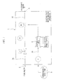
- an electrolysis water-making apparatus 1 includes a raw water line 3A through which raw water (dilution water) flowing from a raw water inlet 2 flows, an electrolyzed products line 3B configured to supply a hydrochloric acid solution, which is a raw material solution, into an electrolytic cell 4 of the electrolysis water-making apparatus 1 and extract electrolyzed products electrolytically treated in the electrolytic cell 4, and an electrolysis water supply line 3C configured to dilute the generated electrolyzed products in the electrolyzed products line 3B and supply electrolyzed water, which becomes the final sterilized water, into an output port 5.
- a raw water line 3A through which raw water (dilution water) flowing from a raw water inlet 2 flows
- an electrolyzed products line 3B configured to supply a hydrochloric acid solution, which is a raw material solution
- an electrolysis water supply line 3C configured to dilute the generated electrolyzed products in the electrolyzed products line 3B and supply electrolyzed water, which becomes the final sterilize
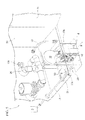
- the respective lines 3A to 3C are accommodated in a casing 20 having a substantially rectangular shape, except for a storage tank 9. For this reason, an opening/shutting door 21 installed as one sidewall of the casing 20 is opened, and the respective parts can undergo proper maintenance, periodic inspection, and so on.
- the raw water line 3A is configured by installing a strainer (not shown), an on-off valve (a solenoid valve) 7, a pressure switch 8, and a check valve (not shown) at a water supply line 6 through which raw water flowing from the raw water inlet 2 flows.
- the on-off valve (the solenoid valve) 7 opens/closes a flow of the raw water at a downstream side of a strainer.
- the pressure switch 8 controls a pressure of the raw water flowing in a piping at a downstream side of the solenoid valve 7.
- the check valve prevents a backward flow of the raw water.
- the raw water inlet 2 and the output port 5 of the electrolyzed water are attached to an intermediate section in a vertical direction of a sidewall 22 of the casing 20.
- the electrolyzed products line 3B includes the storage tank 9 configured to store a hydrochloric acid solution, a pressure pump 10 configured to extrude the hydrochloric acid solution from the storage tank 9 and pump the hydrochloric acid solution to the electrolytic cell 4, and the electrolytic cell 4 configured to electrolyze the pumped hydrochloric acid solution.
- the storage tank 9 and the pump 10 are connected to each other by a first piping 11.
- the pump 10 and the electrolytic cell 4 are connected to each other by a second piping 12.
- the electrolytic cell 4 and the electrolysis water supply line 3C are connected to each other by a third piping 13.
- a connection-point 11a of the first piping 11 and the pump 10 is disposed over the storage tank 9, and is configured such that the hydrochloric acid solution in the piping flows to the storage tank 9 when the first piping 11 is removed from the connection-point 11a.
- the pump 10 is disposed over the electrolytic cell 4, and is configured such that the hydrochloric acid solution in the pump 10 easily flows to the electrolytic cell 4.
- a connection-point 13a of the electrolysis water supply line 3C and the third piping 13 is disposed over a connection-point 13b of the electrolytic cell 4 and the third piping 13, and is configured such that the electrolyzed products in the third piping 13 are stored in the piping 13 not to easily spill out when the third piping 13 is removed from the connection-point 13a.
- All of the first to third pipings 11, 12 and 13 are configured by a flexible tube. For this reason, connection of the piping can be easily performed even when connecting positions of the respective elements are different due to a difference in manufacturing capacity of electrolyzed water of the electrolysis water-making apparatus 1.
- a connector (not shown) is connected to the electrolytic cell 4, and power is supplied from an electrolysis power supply.
- the electrolytic cell 4 is configured such that a unit cell configured to electrolyze the hydrochloric acid solution is formed in a chassis 14.
- the chassis 14 includes side plates 15A and 15B, and a body 16.
- the chassis 14 is formed of plastics such as polyvinyl chloride, polycarbonate, acrylate, and so on. While the electrolytic cell 4 will be described below in detail, treatment capability of the hydrochloric acid solution can be differentiated by increasing or decreasing the number of electrode plates, or the like, disposed in the body 16.
- the body 16 included in the chassis 14 is configured to have different linear dimensions according to the number of electrode plates, or the like.
- the side plates 15A and 15B are rectangular plates having a predetermined thickness.
- the inlet 4a configured to introduce the hydrochloric acid solution is formed under the side plate 15A.
- An outlet 4b (the connection-point 13b) configured to extract the electrolyzed products, which are electrolytically treated, is formed over the side plate 15B.
- a male screw hole (not shown) into which a bolt is threaded is formed at the side plates 15A and 15B.
- the side plates 15A and 15B are set to an appropriate size corresponding to a diameter dimension of the body 16.
- the body 16 is a member having a cylindrical shape.
- a plurality of electrode plates 17, 17 ... and a plurality of spacers 18, 18 ... configured to support the electrode plates 17, 17 ... and form the unit cell are serially installed in a direction perpendicular to a center axis of the body 16.
- the electrolytic cell 4 is configured such that the raw material solution in the electrolytic cell 4 is electrolyzed by electrical conduction to the plurality of electrode plates 17, 17....
- the side plates 15A and 15B are disposed and fixed to water-tightly cover both end apertures of the body 16.
- the pump 10 is constituted by a pump body 27 having a disc shape, and an actuator 28.
- the pump body 27 accommodates a tube and a rotor configured to rotate a roller to crush the tube, and moves the hydrochloric acid solution in the tube by rotation of the rotor.
- the actuator 28 drives the rotor.
- An inlet 27a (the connection-point 11a) configured to suction the hydrochloric acid solution and a delivery 27b configured to pump the hydrochloric acid solution into the electrolytic cell 4 are formed under the pump body 27.
- the electrolytic cell 4 and the pump 10 are integrally attached to a bracket 30 and fixed to an installation base 31 in freely detachable manner in the casing 20 via the bracket 30.
- the bracket 30 makes the replacement process easy when the treatment capability of the electrolytic cell 4 is changed or the electrolytic cell 4 having a decreased generation capability is replaced with a new one.
- the installation base 31 is a member constituting a portion of the casing 20.
- the installation base 37 is formed to approach the opening/shutting door 21 side (hereinafter referred to as "in front of a casing") of the casing 20 over a bottom plate 23, and is constituted by a first base frame 31a and a second base frame 31b, which are separable in one direction.
- the first base frame 31a is constituted by a flat plate area 45 having a substantially rectangular shape, side plates 46 and 46 hanging beneath both edges of a front side and a rear side of the casing, and lower edges 47 and 47 of the plate bent in a direction in which the lower edges approach each other from lower ends of the side plates 46 and 46.
- the lower edges 47 and 47 of the plate are fixed onto the bottom plate 23 by welding.
- the second base frame 31b is a member having substantially the same shape as the first base frame 31a.
- an outside fixed plate 25 having through holes 24 and 24 is installed at a front end 35t of the second base frame 31b.
- the second base frame 31 b is securely fixed to the bottom plate 23 in the outside fixed plate 25 with a bolt (not shown) inserted into the through hole 24.
- male screw holes 32, 32 ... in communication with the through holes 24 and 24 are formed in the bottom plate 23 of the casing 20 at a position to which the outside fixed plate 25 of the second base frame 31b is fixed, and a bolt can be threaded into the bottom plate 23.
- the male screw holes 32, 32 ... are installed in a direction of an arrow L in plural rows, and are set such that the second base frame 31b can be fixed to a position matching the dimension of the bracket 30 to which the electrolytic cell 4 having various dimensions are attached.
- a male screw hole 39 into which a bolt 50 is threaded is formed in the front of the casing of the first base frame 31a, and catching plates 36, 36 ... configured to hold a bottom wall 35 of the bracket 30 are formed.
- the catching plates 36 and 36 are formed by edges of a casing rear side of the first and second base frames 31a and 31b, and a plate-shaped member bent toward the inside of the first and second base frames 31a and 31b after standing upward in the front end 35t of the second base frame 31b shown in FIG. 4 .
- the bracket 30 is formed by bending a sheet material formed of metal, plastic, or the like. As shown in FIG. 4 , the bracket 30 includes the bottom wall 35 fixed to upper surfaces of the installation bases 31a and 31b and attachable to the electrolytic cell 4, a side wall 37 vertically standing up from the edge 35s of a side portion of the bottom wall 35, and a pump fixing portion 38 extending from a side edge in a vertical direction forming the side wall 37 in a direction perpendicular to the side wall 37.
- the bottom wall 35 of the bracket 30 is constituted by first and second sheet materials 35a and 35b separated from each other and having a substantially rectangular shape.
- Rigid walls 40 and 40 having through holes 41 and 41 formed in wall sections, which are standing up, are formed at the first and second sheet materials 35a and 35b, respectively.
- the electrolytic cell 4 is disposed between the rigid walls 40 and 40 separated from each other to have a size slightly larger than the linear dimension of the electrolytic cell 4, and bolts 51 and 51 are threaded and fixed into the male screw holes of the through holes 41 and 41 and the side plates 15A (one end of the electrolytic cell 4) and 15B (the other end of the electrolytic cell).
- the electrolytic cell 4 is disposed between the first and second sheet materials a and 35b.
- a through hole 33 in communication with the male screw hole 39 formed in the installation base 31 is formed in the first sheet material 35a of the bottom wall 35.
- the bottom wall 35 is detachably attached to the installation base 31 by inserting and securing the bolt 50 into the through hole 33 and the male screw hole 39 while an end of the bottom wall 35 is disposed under the catching plates 36, 36 ... of the installation base 31.
- the side wall 37 of the bracket 30 has the pump fixing portion 38 formed thereon.
- the side wall 37 is configured such that the pump 10 shown in FIG. 2 and attached to the pump fixing portion 38 can be disposed at a higher dimension than the storage tank 9 and the electrolytic cell 4.
- the pump fixing portion 38 is formed to extend from an upper side edge of the side wall 37 along the opening/shutting door 21 of the casing 20.
- An aperture 42 configured to mount the pump 10 is formed inside the pump fixing portion 38.
- the actuator 28 is inserted into the aperture 42 shown in FIG. 4 , and the pump body 27 and the pump fixing portion 38 are fixed by a fixture (not shown).
- the pair of hooks 42a and 42a are formed at the aperture 42.
- a pair of catching plates (not shown) snap-fitted to the hook 42a protrude from a rear side (a side in contact with the pump fixing portion 38) of the pump body 27 of the pump 10.
- the hook 42a is fitted to the catching plate of the pump 10 to reach a location of installation of the pump 10.
- the pump 10 is attached to the bracket 30, first, the actuator 28 is inserted into the aperture 42. At this time, a pair of catching plates (not shown) formed at a rear side of the pump body 27 are inserted to be fitted to the pair of hooks 42a and 42a formed at the aperture 42. As the hooks 42a and 42a are fitted to the pair of catching plates of the pump 10, an angle of the pump 10 with respect to the bracket 30 always becomes a certain angle, and the pump 10 is prevented from being pivoted with respect to the bracket 30. Then, the pump 10 is appropriately fixed by a pump body 17 and a fastener such as a bolt or a clip (not shown) installed at the pump fixing portion 38 with the pump fixing portion 38 interposed therebetween.
- a fastener such as a bolt or a clip
- the electrolysis water supply line 3C dilutes the electrolyzed products extracted from the electrolytic cell 4 by the raw water of the water supply line 6, and configures a dilution method 26 of generating electrolyzed water.
- the electrolysis water supply line 3C is formed at the most downstream end of the water supply line 6.
- the water supply line 6, the electrolytic cell 4, the pump 10, and a portion of the pump 10 side of the first piping 11, the second and third pipings 12 and 13, which connect them, are accommodated in the casing 20.
- the electrolytic cell 4 and the pump 10 are integrally and detachably attached to the bracket 30 such that they can be easily extracted from the opening/shutting door 21 of the casing 20. Further, the bracket 30 is securely fixed to the installation base 31 in the casing 20 by the bolt 50.
- the first piping 11 is removed from the connection-point 11 a of the pump 10, and the hydrochloric acid solution remaining in the first piping 11 flows to the storage tank 9.
- the third piping 13 is removed from the connection-point 13a with the dilution method 26.
- the removed third piping 13 is maintained in a state in which the aperture is directed upward such that the electrolyzed products remaining in the third piping 13 do not spill out.
- the bracket 30 is extracted in front of the casing (the direction of the arrow P).
- the electrolytic cell 4 and the pump 10 of each bracket 30 are extracted from the casing 20.
- the bracket 30 is moved to a place where waste liquid treatment can be easily performed and the hydrochloric acid solution or the like can be discarded, and the electrolyzed products in the third piping 13 are discharged.
- the second piping 12 connecting the pump 10 to the electrolytic cell 4 is removed from an inlet 27b of the pump 10, and the hydrochloric acid solution remaining in the second piping 12 is discharged.
- the bolts 51 and 51 shown in FIG. 4 are removed to remove the electrolytic cell 4 from the bracket 30. Accordingly, the first sheet material 35a and the second sheet material 35b are separated from each other.
- the side plates 15A and 15B of the electrolytic cell 4 after the replacement are fixed to the outside of the casing 20 by the bolts 51 and 51 of the rigid walls 40 and 40 of the first and second sheet materials 35a and 35b. In this way, the bottom wall 35 of the bracket 30 is connected via the electrolytic cell 4, and the electrolytic cell 4 and the pump 10 shown in FIG. 2 are integrally attached to the bracket 30.
- the second piping 12 is connected to an inlet 4a of the electrolytic cell 4 and the delivery 27b of the pump 10.
- a position thereof is changed. That is, a bolt (not shown) of the outside fixed plate 25 fixing the second base frame 31b is removed.
- the second base frame 31b is moved to a position at which the entire bottom wall 35 of the bracket 30 on which the electrolytic cell 4 having a large dimension shown in FIG.
- the first piping 11 is connected to the inlet 27a of the pump 10, and the third piping 13 is connected between the outlet 4b of the electrolytic cell 4 and the dilution method 26. Then, the opening/shutting door of the casing 20 is closed to complete replacement of the electrolytic cell 4.
- the bracket 30 to which the electrolytic cell 4 is attached and the installation base 31 of the casing 20 at which they are installed can be set to be modified according to the linear dimension of the electrolytic cell 4.
- the electrolytic cell 4 having different treatment capability can be installed at the electrolysis water-making apparatus 1. and the one electrolysis water-making apparatus 1 can appropriately change the manufacturing capacity of electrolyzed water.
- bracket 30 can be removed, and the pump 10 and the electrolytic cell 4 can be extracted from each bracket 30 to the outside of the casing 20 to perform the waste liquid treatment, and so on. Accordingly, a process of replacing the inside of the pump 10, the electrolytic cell 4, and the first to third pipings 11, 12 and 13 by water can be omitted, the replacement process of the electrolytic cell 4 and the pump 10 can be easily and efficiently performed, and water used in the replacement process can be saved.
- connection-point 11a of the pump 10 and the first piping 11 is installed over the storage tank 9. For this reason, when the first piping 11 is removed from the pump 10, the hydrochloric acid solution in the first piping 11 flows to the storage tank 9 to make it difficult to overflow in the casing 20.
- connection-point 13a of the third piping 13 and the dilution method 26 is connected to the electrolytic cell 4 at a position higher than the connection-point 13b, when the third piping 13 is removed from the connection-point 13a, the electrolyzed products in the third piping 13 do not easily overflow in the casing 20.
- the bolt 50 of the bracket 30 is removed, the first piping 11 is removed from the inlet 27a of the pump 10, the third piping 13 is removed from the connection-point 13a of the dilution method 26, and thus, the bracket 30 can be extracted from the casing 20. For this reason, a process in the casing 20 can be suppressed to a minimum level, and the replacement process can be easily performed.
- the pump 10 and the electrolytic cell 4 can be integrally and easily moved to a place where a process can be easily performed while attached to the bracket 30.
- the manufacturing cost of the electrolysis water-making apparatus 1 can be reduced to a low level.
- the linear dimension of the first and third pipings 11 and 13 may be set to be larger, and the bracket 30 may be extracted to the outside of the casing 20 in a state in which the first and third pipings 11 and 13 are connected to the pump 10 and the electrolytic cell 4.
- the first and third pipings 11 and 13 can be removed from the casing 20. For this reason, even when the liquid in the piping overflows upon removal of these pipings, contamination of the inside of the casing 20 can be avoided. In addition, when a sheet or a plate is prepared at the outside of the casing 20, a process of removing the first and third pipings I 1 and 13 can be more easily performed.
- the second sheet material 35b and the second base frame 31 b are constituted by separate members, these members may be integrally formed with each other, and the outside fixed plate 25 may be formed at the second sheet material 35b to be directly fixed to the bottom plate 23.
- a first base frame 60a of an installation base 60 is flexibly connected to a second base frame 60b. Accordingly, the second embodiment is distinguished from the electrolysis water-making apparatus 1 according to the first embodiment in that the second base frame 60b is extracted from or accommodated in the first base frame 60a.
- the first base frame 60a is constituted by a flat plate area 61 having a substantially rectangular shape and on which a first sheet material 30a of a bracket 30 is disposed, side plates 62 and 62 disposed in front of a casing and vertically hanging down from both edges of a rear side thereof, and lower edges 63 and 63 of the plate bent in a direction in which the lower edges approach each other from both ends of the side plates 62 and 62.
- the first base frame 60a is formed such that the side plates 62 and 62 and the lower edges of the plates 63 and 63 protrude in a direction in which the second base frame 60b is positioned, rather than the flat plate area 61.
- the lower edges of the plate 63 and 63 are fixed to the bottom plate 23 of the casing 20 shown in FIG. 2 by welding.
- a slot 64 is formed at a middle section in a width direction of the side plate 62 in a longitudinal direction of the side plate 62.
- a latching section 66 protruding toward the outside of the side plates 62 and 62 and constituting one side of a fixation mechanism 65 configured to relatively position the second base frame 60b with respect to the first base frame 60a is formed at a front end of the side plate 62.
- the second base frame 60b is constituted by a flat plate area 67 having a substantially rectangular shape and on which a second sheet material 30b of the bracket 30 is disposed, and side plates 68 and 68.
- the side plate 68 protrudes in a direction of the first base frame 60a rather than the flat plate area 67 and is disposed outside the side plates 62 and 62.
- cutout sections 71, 71... constituting the other side of the fixation mechanism 65 are formed at lower ends of the side plates 68 and 68 at predetermined intervals. As shown in FIGS. 8A and 8B , the cutout sections 71, 71... are locked by the latching section 66 at a position where the dimension between the rigid walls 40 and 40 is substantially the same as the dimension of various electrolytic cells 4.
- a method of replacing the electrolytic cell 4 is distinguished from the first embodiment in settings of the electrolysis water-making apparatus I and the installation base 60 according to the first embodiment. That is, in order to set the installation base 60 of the second embodiment according to a dimension between the electrolytic cell 4 and the bracket 30 to which the electrolytic cell 4 is attached, after the bracket 30 is removed from the installation base 60, the second base frame 60b is raised upward from the steel rod 70 as a starting point, and engagement between the latching section 66 and the cutout section 71 is released.
- the second base frame 60b is relatively moved with respect to the first base frame 60a, the second base frame 60b is returned to a horizontal position at a position having a predetermined width dimension, and the engaging section 66 is engaged with the cutout section 71 formed at the position.
- the bracket 30 attached to the electrolytic cell 4 in the same manner as the electrolysis water-making apparatus 1 according to the first embodiment is attached to the installation base 60 and connects the various pipings 11 and 13, and the opening/shutting door 21 of the casing 20 is closed to complete replacement of the electrolytic cell 4.
- the installation base 60 can be easily set to match the linear dimension of the electrolytic cell 4. Further, when the electrolytic cell 4 is replaced with a new one having a different dimension, a process of fixing the second base frame 60b to the bottom plate 23 of the casing 20 one by one can be omitted.
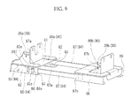
- a first base frame 80a of an installation base 80 is flexibly connected to a second base frame 80b.
- the installation base 60 in the second embodiment is similar to the third embodiment in that the second base frame 80b is extracted from and accommodated in the first base frame 80a to adjust a length thereof.
- the electrolysis water-making apparatus according to the third embodiment is different in a fixation mechanism.
- the first base frame 80a is formed by a flat plate area 81 having a substantially rectangular shape, side plates 82 and 82 disposed in front of the casing and hanging down from both ends of a rear side thereof, and lower edges 83 and 83 of the plate bent in a direction in which both edges approach each other from both ends of the side plates 82 and 82.
- the lower edges 83 and 83 of the plate are fixed onto the bottom plate 23 shown in FIG. 2 by welding.
- Latching holes 85. 85... having a substantially rectangular shape and forming one side of a fixation mechanism 84 are formed at the side plates 82 and 82 of the first base frame 80a at predetermined intervals.
- the second base frame 80b has substantially the same shape as the first base frame 80a.
- the second base frame 80b has a flat spring 87 fixed to inner surface sides of the side plates 86 and 86, extending to the entire first base frame 80a side, and forming the other side of the fixation mechanism 84, instead of having a hole of the latching hole 85 in the side plate 86.
- the flat spring 87 is configured to have a latching section 88.
- the latching section 88 has a slightly smaller width dimension than a dimension in the vertical direction of the latching hole 85, and is formed as will be described below. That is, a base end side 87b is fixed to inner surfaces of the side plates 86 and 86, extends toward the first base frame 80a, and expands from inner surfaces of the side plates 82 and 82 toward outer surfaces in a front end 87a. The expanded portion protrudes from the latching hole 85 to be latched by the latching hole 85.
- the flat springs 87 and 87 can be elastically deformed in a direction in which the fat springs 87 and 87 approach each other between the side plates 82 and 82 of the first base frame 80a from a base end 87b fixed to the side plates 86 and 86 as a starting point.
- the flat springs 87 and 87 are configured to be elastically deformed when the latching section 88 is disposed at a position abutting the inner surface of the side plate 82 and to be elastically recovered when the latching section 88 is disposed at the latching hole 85 to be engaged with the latching hole 85.
- a method of replacing the electrolytic cell 4 is distinguished from the electrolysis water-making apparatus according to the second embodiment in settings of the installation base 80.
- the bracket 30 is removed from the installation base 80.
- the second base frame 80b is extracted from the first base frame 80a or pressed toward the first base frame 80a side to bring an expanding surface 88a of the latching section 88 of the flat spring 87 in contact width an aperture edge 85a of the latching hole 85 and slides, releasing engagement between the latching section 88 and the latching hole 85.
- an expended apex 85T of the latching section 88 abuts the inner surface of the side plate 82, and the flat spring 87 is elastically deformed.
- the second base frame 80b is moved.
- the flat spring 87 is elastically recovered so that an engaging section 88 protrudes to be engaged in the latching hole 85.
- the installation base 80 can be set to match the bracket 30 to which the electrolytic cell 4 having a different dimension is attached.
- an electrolysis water-making apparatus is distinguished from the first to third embodiments in that the entire bottom wall 35 of the bracket 30 is integrally formed, a plurality of kinds of dimensions between the rigid walls 40 and 40 formed to match the dimension of the electrolytic cell 4 are provided, and the entire bottom wall 35 is replaced to correspond to the dimension of the electrolytic cell 4.
- the entire bottom wall 35 of the bracket 30 is integrally formed of a sheet material.
- the bottom wall 35 is fixed to a lower end of the side wall 37 by fixtures 90 and 90 such as a screw and so on.
- the bracket 30 is disposed between the first and second base frames 31 a and 31b, and fixed by the catching plates 36, 36... and the bolt 50.
- the bracket 30 is removed from the installation base 31. Further, as the fixtures 90 and 90 are removed, the bottom wall 35 is removed from the side wall 37. After that, the electrolytic cell 4 is attached to the bottom wall 35 having a dimension between the rigid walls 40 and 40 appropriate for the dimension of the newly attached electrolytic cell 4 and fixed to the side wall 37 so that replacement of the electrolytic cell 4 is performed. Attachment to the installation base 31 is similar to the electrolysis water-making apparatus 1 according to the first embodiment. In the embodiment, instead of the installation base 31, the installation base 60 or 80 according to the second or third embodiment may be used.
- the dimension between the rigid walls 40 and 40 is previously formed to match the dimension between the side plates 15A and 15B of the electrolytic cell 4. For this reason, since replacement efficiency of the electrolytic cell 4 can be increased and configuration of the bottom wall 35 becomes simple without necessity of dimension adjustment of the bottom wall 35, manufacturing cost of the bracket 35 can be suppressed.
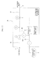
- an electrolysis water-making apparatus 1A includes a hydrochloric acid dilution line 3D in addition to the configuration of the electrolysis water-making apparatus 1 according to the first embodiment.
- the hydrochloric acid dilution line 3D has a starting end branched from the raw water line 3A, and a terminating end joined to an upstream side of the electrolytic cell 4 in the electrolyzed products line 3B. Further, the hydrochloric acid dilution line 3D includes a dilution water feed pump 100.
- the dilution water feed pump 100 extracts raw water from the raw water line 3A, and mixes the raw water with a hydrochloric acid solution before electrolysis.
- the dilution water feed pump 100 can appropriately adjust a concentration of the hydrochloric acid solution supplied into the electrolytic cell 4.
- the electrolysis water-making apparatus 1A according to the fifth embodiment includes the dilution water feed pump 100 in addition to the configuration of the electrolysis water-making apparatus 1 according to the first embodiment.
- the electrolysis water-making apparatus 1A according to the embodiment is distinguished from the electrolysis water-making apparatus 1 of the first embodiment in that a bracket 102 is configured to be capable of holding the dilution water feed pump 100 adding to the electrolytic cell 4 and a raw material solution feed pump 10.
- the dilution water feed pump 100 suctions dilution water from the water supply line 6, and delivers the dilution water into the second piping 12 connected to the inlet 4a of the electrolytic cell 4.
- the dilution water feed pump 100 has the same configuration of the pressure pump 10 configured to pump the hydrochloric acid solution. That is, the dilution water feed pump 100 includes a pump body 103 having a disc shape, and an actuator 104.
- the pump body 103 accommodates a tube and a rotor configured to rotate a roller to crush the tube, and moves the diluted water in the tube by rotation of the rotor.
- the actuator 104 drives the rotor.
- An inlet 103a configured to suction the diluted water and a delivery 103b configured to pump the diluted water toward the second piping 12 are formed under the pump body 103.
- a fourth piping 110 is connected between the inlet 103a of the pump 100 and the water supply line 6.
- a fifth piping 111 is connected between the delivery 103b and the second piping 12.
- the bracket 102 has an aperture 42 configured to hold the pump 10 at a pump fixing portion 105, and an aperture 106 configured to hold the pump 100.
- the bracket 102 includes a fastener such as a bolt, a clip, or the like (not shown) configured to hold the pumps 10 and 100.
- a pair of hooks 106a and 106a and a pair of hooks 106b and 106b are formed at the aperture 106.
- a pair of catching plates (not shown) snap-fitted to the hooks 106a or the hooks 106b protrude to a rear side (a side in contact with the pump fixing portion 105) of the pump body 103 of the pump 100.
- the hooks 106a or the hooks 106b are fitted to the catching plates of the pump 100 to reach a location at which the pump 100 is installed.
- the actuator 104 When the pump 100 is attached to the bracket 102, first, the actuator 104 is inserted into the aperture 106.
- a pair of catching plates (not shown) formed at the rear side of the pump body 103 are inserted to be fitted to the pair of hooks 106a and 106a formed at the aperture 106. Accordingly, an angle of the pump 100 with respect to the bracket 102 always has a certain angle, and the pump 100 is prevented from being pivoted with respect to the bracket 102.
- the pump fixing portion 105 is sandwiched by a fastener such as a bolt or a clip (not shown) installed at the pump body 103 and the pump fixing portion 105 to appropriately fix the pump 100.
- a fastener such as a bolt or a clip (not shown) installed at the pump body 103 and the pump fixing portion 105 to appropriately fix the pump 100.
- a pair of catching plates (not shown) are fitted to the pair of hooks 106a and 106a
- the catching plates may be fitted to the pair of hooks 106b and 106b.
- the pair of hooks 106b and 106b are formed at a position where a straight line connecting the hooks 106b and 106b is substantially perpendicular to a straight line connecting the hooks 106a and 106a. For this reason, when the catching plates of the pump 100 are fitted to the hooks 106b and 106b, the pump 100 is attached at an angle rotated 90 degrees counterclockwise (when seen from a front side of the casing or a side of the pump body 103) in comparison with the case in which the catching plates are fitted to the hooks 106a and 106a.
- a side wall 107 of the bracket 102 is a wall section vertically standing upward from an edge 35s of a side portion of the bottom wall 35.
- the side wall 107 includes a bent section 107a configured to prevent the side wall 107 from being bent due to weights of the pumps 10 and 100 when the pumps 10 and 100 are attached to the pump fixing portion 105.
- a bent section 105a is also formed at an upper end of the pump fixing portion 105. The bent section 105a prevents the pump fixing portion 105 from being bent due to the weights of the pumps 10 and 100 when the pumps 10 and 100 are attached thereto.
- the pressure pump 10 configured to pump the hydrochloric acid solution, and the dilution water feed pump 100 of the electrolysis water-making apparatus 1A, the bolt 50 of the bracket 102 is removed, and the bracket 102 can be extracted.
- the first piping 11 is removed from the connection-point 11a of the pump 10 to return the hydrochloric acid solution to the storage tank 9.
- the third piping 13 and the fourth piping 110 are removed in the connection-point 13a of the dilution method 26 and a connection-point 103a of the water supply line 6 side, respectively. Then, apertures of the third and fourth the pipings 13 and 110 are maintained upward.
- the bracket 102 to which the electrolytic cell 4 and the pumps 10 and 100 are attached is extracted to the outside of the casing 20 to discard the chloride solution and electrolyzed products in the piping. Further, the second and fifth pipings 12 and 111 are removed, and a member required to be replaced is replaced with a new one, which is then fixed to the bracket 102. Then, the second and fifth pipings 12 and 111 are connected again, and the bracket 102 is installed at/fixed to the installation base 31 in the easing 20. Next, the first, third and fourth pipings 11, 13 and 110 are connected to predetermined connection points to close the opening/shutting door 21 of the casing 20, completing replacement of the member.
- the electrolysis water-making apparatus 1A of the fifth embodiment even when the fifth piping 111 and the dilution water feed pump 100 are connected to the second piping 12 configured to deliver the hydrochloric acid solution to the electrolytic cell 4 to complicate a connecting relation of the piping, only the minimum piping connected to the storage tank 9 and the water supply line 6 is removed, and the electrolytic cell 4 and the pumps 10 and 100 are integrally and easily transported to the outside of the casing 20 by the bracket 102, enabling the replacement process.
- the electrolytic cell 4 and the pumps 10 and 100 can be integrally transported to the outside of the casing 20 by the bracket 102.
- the piping configured to connect the respective members is removed, waste liquid treatment becomes easy, and the inside of the casing 20 is cleaned by the chloride solution and electrolyzed products with no contamination, a working efficiency can be increased.
- connection-points 103a and 103b of the pump 100 are fixed to be horizontally disposed with respect to the bracket 102, layout of the piping becomes free to easily secure a working space.
- the electrolytic cells having various dimensions can be assembled to one electrolysis water-making apparatus, and the manufacturing capacity of electrolyzed water can be changed.
- the attachment process of the electrolytic cell can be performed outside the casting, and the replacement process of the electrolytic cell can be easily performed.
Landscapes
- Chemical & Material Sciences (AREA)
- Organic Chemistry (AREA)
- Engineering & Computer Science (AREA)
- Chemical Kinetics & Catalysis (AREA)
- Electrochemistry (AREA)
- Water Supply & Treatment (AREA)
- Hydrology & Water Resources (AREA)
- Environmental & Geological Engineering (AREA)
- Life Sciences & Earth Sciences (AREA)
- General Chemical & Material Sciences (AREA)
- Inorganic Chemistry (AREA)
- Materials Engineering (AREA)
- Metallurgy (AREA)
- Water Treatment By Electricity Or Magnetism (AREA)
- Electrolytic Production Of Non-Metals, Compounds, Apparatuses Therefor (AREA)
Abstract
Description
- The present invention relates to an electrolysis water-making apparatus for making electrolyzed water used as sterilized water by electrolyzing a raw material solution.
Priority is claimed on Japanese Patent Application No.2010-124880 filed on May 31, 2010 - In the related art, electrolyzed water obtained by performing electrolysis on a solution including chlorine ions is known to have a low available chlorine concentration and a high chlorine sterilizing effect, and to have an advantageous property of high safety for humans. The electrolyzed water is used to sterilize foods and instruments for processing the foods in food-related fields, or the like.
In particular, in recent times, since accurate quality/sanitary management of foods and goods for treating the foods is strongly required, utilization of the electrolysis water-making apparatus for making the electrolyzed water (sterilized water) is further expected. - The electrolysis water-making apparatus includes an electrolytic cell configured to perform electrolysis on a raw material solution such as a hydrochloric acid solution or the like, a tank of a raw material solution such as hydrochloric acid or the like, a water supply system, a pump configured to pump a hydrochloric acid solution/dilution water or the like, an installation base of an electrolytic cell or the like, a mixer, a pipe group configured to connect the elements of this equipment, an electrolysis power supply configured to supply power to the electrolytic cell, and so on. For example, the apparatuses disclosed in the following
Patent Documents - In these electrolysis water-making apparatuses, a productive capacity of electrolysis is determined and a manufacturing capacity of electrolyzed water of the electrolysis water-making apparatus is determined by the total electrode surface area of electrode plates assembled to the electrolytic cell. The conventional electrolysis water-making apparatus is configured such that one kind of electrolytic cell is incorporated with one apparatus. For this reason, the manufacturing capacity of electrolyzed water is different in the respective electrolysis water-making apparatuses. Then, a user selects and uses an apparatus capable of generating a necessary amount of electrolyzed water from various kinds of electrolysis water-making apparatuses having a predetermined manufacturing capacity of electrolyzed water.
- In addition, in the conventional electrolysis water-making apparatus, the electrolytic cell or the like can be replaced with a new one to prepare a case in which the lifespan of an electrode plate is terminated due to use or a tube or a diaphragm of the pump is deteriorated. Replacement of the electrolytic cell is performed through a task of replacing the inside of the respective members by water from a chloride solution and electrolyzed products such that the chloride solution and electrolyzed products or a gas in the electrolytic cell or the like does not leak and stick to a body or clothes.
-
- [Patent Document 1] Japanese Unexamined Patent Application, First Publication No.
H11-169856 - [Patent Document 2] Japanese Unexamined Patent Application, First Publication No.
2001-62455 - However, the amount of electrolyzed water required by the user is not always constant. For this reason, one apparatus may exceed a capability of the electrolysis water-making apparatus or may cause lack of a generation capability. Then, in order to change the capacity of the electrolyzed water, the electrolysis water-making apparatus should be separately prepared to replace the entire apparatus with a new one, increasing cost or causing inconvenience in installation space. For this reason, development of an electrolysis water-making apparatus that can be replaced with respect to different electrolytic cells to correspond to a change in the demand of electrolyzed water is expected.
- In addition, in the related art, replacement of the electrolytic cell is performed through a task of replacing the inside of the electrolytic cell or a piping by water. This water should be used in the replacement task only and then discarded after the task. In addition, time is consumed for the task of replacing the inside of electrolytic cell or the inside of piping by water. From the above, in order to enable replacement of the electrolytic cell of the electrolysis water-making apparatus according to the generation capability, the replacement task of water may be omitted so that the replacement process can be simply performed.
- According to a first aspect of the present invention, an electrolysis water-making apparatus for generating electrolyzed products by supplying a raw material solution into an electrolytic cell to perform electrolysis, and generating electrolyzed water by diluting the electrolyzed products, includes a casing configured to accommodate the electrolytic cell; and a bracket fixed to the casing in a freely detachable manner. The bracket includes a pair of rigid walls to which one end and the other end of the electrolytic cell are attached. The pair of rigid walls have a dimension therebetween that is adjustable according to a linear dimension of the electrolytic cell.
- According to a second aspect of the present invention, a pressure pump configured to pump the raw material solution into the electrolytic cell is attached to the bracket.
- According to a third aspect of the present invention, the electrolysis water-making apparatus further includes a dilution water feed pump configured to pump dilution water into the electrolytic cell. The dilution water feed pump is attachable to the bracket.
- According to a fourth aspect of the present invention, the dilution water feed pump is attached to the bracket at a variable angle.
- According to a fifth aspect of the present invention, the casing includes a main body casing; a first base frame fixed to a bottom plate of the main body casing; and a second base frame installed at the first base frame in a freely disjunctive manner, and fixed to the bottom plate in a freely detachable manner. One of the pair of rigid walls included in the bracket is fixed to the first base frame included in the casing. The other of the rigid walls included in the bracket is fixed to the second base frame included in the casing.
- According to a sixth aspect of the present invention, the casing includes a main body casing; a first base frame fixed to a bottom plate of the main body casing; and a second base frame installed at the first base frame in a freely disjunctive manner, and fixed to the bottom plate in a freely detachable manner. A plurality of brackets having different dimensions between the rigid walls according to the linear dimension of the electrolytic cell are provided. The bracket is fixed between the first and second base frames in a state in which the electrolytic cell is fixed.
- According to a seventh aspect of the present invention, the casing includes a main body casing; a first base frame fixed to a bottom plate of the main body casing; and a second base frame flexibly installed with respect to the first base frame, and a fixation mechanism configured to fix the first and second base frames at an original position is provided.
- According to the electrolysis water-making apparatus of the present invention, the above-mentioned means has the following effects.
That is, according to the electrolysis water-making apparatus in accordance with the first aspect of the present invention, the electrolytic cell is attached to the bracket detachably attached to the installation base. The bracket can adjust the rigid walls according to the linear dimension of the electrolytic cell. For this reason, the electrolytic cells having various different dimensions can be assembled to one electrolysis water-making apparatus, and manufacturing capacity of electrolyzed water can be changed. - In addition, the electrolytic cell is attached to the bracket, and the bracket is detachably attached to the casing. For this reason, the attachment process of the electrolytic cell can be performed outside the casing, and the replacement process of the electrolytic cell can be easily performed.
- According to the electrolysis water-making apparatus in accordance with the second aspect of the present invention, the electrolytic cell and the pump are integrally removed from the installation base by the bracket, and treatment of liquid in the electrolytic cell or the pump can be performed after movement to the outside of the casing. For this reason, in replacement of the electrolytic cell or the pump, a process of replacing the inside of the electrolytic cell by water can be omitted, and working efficiency of the replacement can be increased.
- In addition, since the process of replacing the inside of the electrolytic cell with water can be omitted, water can be saved.
- Further, since waste liquid treatment in the electrolytic cell or the like can be performed outside the casing, the process can be easily and safely performed. Furthermore, since the liquid in the casing does not easily spill out, a cleaning process of the casing can be omitted.
- In addition, in order to enable the replacement of the electrolytic cell, since only the bracket to which the electrolytic cell and the pump are integrally attached is used, the structure of the electrolysis water-making apparatus can be simplified to reduce the manufacturing cost.
- According to the electrolysis water-making apparatus in accordance with the third aspect of the present invention, the dilution water feed pump can be attached to the bracket. For this reason, the bracket can be extracted to the outside of the casing to perform the replacement process of the dilution water feed pump, and thus the replacement process becomes easy.
- According to the electrolysis water-making apparatus in accordance with the fourth aspect of the present invention, when the dilution water feed pump is attached to the bracket, an angle between the dilution water feed pump and the bracket can be appropriately selected to perform the attachment. For this reason, for example, when workability is bad due to interference with the piping of the dilution water feed pump, the dilution water feed pump can be attached to the bracket by varying the angle of the dilution water feed pump, and the workability can be further improved.
- According to the electrolysis water-making apparatus in accordance with the fifth aspect of the present invention, the second base frame fixed to the casing is installed at the first base frame in a freely disjunctive manner. For this reason, the position of the second base frame can be freely set to match the linear dimension of the bracket, and the bracket and the electrolytic cell can be stably and securely attached in the casing.
- According to the electrolysis water-making apparatus in accordance with the sixth aspect of the present invention, the electrolytic cell is fixed to the installation base of the casing by selecting the bracket having the rigid walls formed to match the dimension of the electrolytic cell. For this reason, the electrolytic cell can be simply attached to the bracket, the configuration of the bracket can be extremely simplified, and thus the manufacturing cost of the bracket can be reduced.
- According to the electrolysis water-making apparatus in accordance with the seventh aspect of the present invention, the fixation mechanism configured to fix the first and second base frames at an original position is provided. For this reason, the second base frame can be securely fixed in the casing without using a separate fixture, and settings of the base frame can be easily performed.
-
-
FIG. 1 is a view schematically showing a configuration of an electrolysis water-making apparatus according to a first embodiment of the present invention. -
FIG. 2 is a perspective view showing the inside of the electrolysis water-making apparatus according to the first embodiment of the present invention. -
FIG. 3 is an exploded perspective view showing a configuration of an electrolytic cell of the electrolysis water-making apparatus according to the first embodiment of the present invention. -
FIG. 4 is a perspective view showing a bracket of the electrolysis water-making apparatus according to the first embodiment of the present invention. -
FIG. 5 is a perspective view showing a state in which the bracket of the electrolysis water-making apparatus according to the first embodiment of the present invention is removed from a casing. -
FIG. 6 is a perspective view showing the bracket of the electrolysis water-making apparatus according to the first embodiment of the present invention. -
FIG. 7 is a perspective view showing portions of a bracket and an installation base of an electrolysis water-making apparatus according to a second embodiment of the present invention. -
FIG. 8A is a perspective view showing the bracket and the installation base of the electrolysis water-making apparatus according to the second embodiment of the present invention. -
FIG. 8B is a perspective view showing the bracket and the installation base of the electrolysis water-making apparatus according to the second embodiment of the present invention. -
FIG. 9 is a perspective view showing portions of a bracket and an installation base of an electrolysis water-making apparatus according to a third embodiment of the present invention. -
FIG. 10A is a perspective view showing the bracket and the installation base of the electrolysis water-making apparatus according to the third embodiment of the present invention. -
FIG. 10B is a perspective view showing the bracket and the installation base of the electrolysis water-making apparatus according to the third embodiment of the present invention. -
FIG. 11A is a perspective view showing a bracket and an installation base of an electrolysis water-making apparatus according to a fourth embodiment of the present invention. -
FIG. 11B is a perspective view showing the bracket and the installation base of the electrolysis water-making apparatus according to the fourth embodiment of the present invention. -
FIG. 12 is a view schematically showing a configuration of an electrolysis water-making apparatus according to a fifth embodiment of the present invention. -
FIG. 13 is a perspective view showing the inside of the electrolysis water-making apparatus according to the fifth embodiment of the present invention, and -
FIG. 14 is an exploded perspective view showing a bracket of the electrolysis water-making apparatus according to the fifth embodiment of the present invention. - Hereinafter, embodiments of an electrolysis water-making apparatus according to the present invention will be described with reference to the accompanying drawings.
- Here, a raw material solution including chlorine ions, which are a raw material of electrolyzed water, is, for example, water including chlorine ions such as a sodium chloride solution, a hydrochloric acid solution, or the like.
- The electrolysis water-making apparatus according to the present invention perform electrolysis on the above-mentioned raw material solution, generates chlorine gas by action of electrolytic oxidation, and dissolves the generated chlorine gas in water, generating hypochlorous acid in the water.
- As shown in
FIG. 1 , an electrolysis water-makingapparatus 1 includes araw water line 3A through which raw water (dilution water) flowing from araw water inlet 2 flows, anelectrolyzed products line 3B configured to supply a hydrochloric acid solution, which is a raw material solution, into anelectrolytic cell 4 of the electrolysis water-makingapparatus 1 and extract electrolyzed products electrolytically treated in theelectrolytic cell 4, and an electrolysiswater supply line 3C configured to dilute the generated electrolyzed products in the electrolyzedproducts line 3B and supply electrolyzed water, which becomes the final sterilized water, into anoutput port 5.
As shown inFIG. 2 , therespective lines 3A to 3C are accommodated in acasing 20 having a substantially rectangular shape, except for astorage tank 9. For this reason, an opening/shuttingdoor 21 installed as one sidewall of thecasing 20 is opened, and the respective parts can undergo proper maintenance, periodic inspection, and so on. - The
raw water line 3A is configured by installing a strainer (not shown), an on-off valve (a solenoid valve) 7, a pressure switch 8, and a check valve (not shown) at awater supply line 6 through which raw water flowing from theraw water inlet 2 flows. The on-off valve (the solenoid valve) 7 opens/closes a flow of the raw water at a downstream side of a strainer. The pressure switch 8 controls a pressure of the raw water flowing in a piping at a downstream side of the solenoid valve 7. The check valve prevents a backward flow of the raw water. - In the
water supply line 6, theraw water inlet 2 and theoutput port 5 of the electrolyzed water are attached to an intermediate section in a vertical direction of asidewall 22 of thecasing 20. - The
electrolyzed products line 3B includes thestorage tank 9 configured to store a hydrochloric acid solution, apressure pump 10 configured to extrude the hydrochloric acid solution from thestorage tank 9 and pump the hydrochloric acid solution to theelectrolytic cell 4, and theelectrolytic cell 4 configured to electrolyze the pumped hydrochloric acid solution. Thestorage tank 9 and thepump 10 are connected to each other by afirst piping 11. Thepump 10 and theelectrolytic cell 4 are connected to each other by asecond piping 12. Further, theelectrolytic cell 4 and the electrolysiswater supply line 3C are connected to each other by athird piping 13. - In this configuration, a connection-
point 11a of thefirst piping 11 and thepump 10 is disposed over thestorage tank 9, and is configured such that the hydrochloric acid solution in the piping flows to thestorage tank 9 when thefirst piping 11 is removed from the connection-point 11a. In addition, thepump 10 is disposed over theelectrolytic cell 4, and is configured such that the hydrochloric acid solution in thepump 10 easily flows to theelectrolytic cell 4. A connection-point 13a of the electrolysiswater supply line 3C and thethird piping 13 is disposed over a connection-point 13b of theelectrolytic cell 4 and thethird piping 13, and is configured such that the electrolyzed products in thethird piping 13 are stored in the piping 13 not to easily spill out when thethird piping 13 is removed from the connection-point 13a. - All of the first to
third pipings apparatus 1. In addition, a connector (not shown) is connected to theelectrolytic cell 4, and power is supplied from an electrolysis power supply. - The
electrolytic cell 4 is configured such that a unit cell configured to electrolyze the hydrochloric acid solution is formed in achassis 14. Thechassis 14 includesside plates body 16. Thechassis 14 is formed of plastics such as polyvinyl chloride, polycarbonate, acrylate, and so on. While theelectrolytic cell 4 will be described below in detail, treatment capability of the hydrochloric acid solution can be differentiated by increasing or decreasing the number of electrode plates, or the like, disposed in thebody 16. Thebody 16 included in thechassis 14 is configured to have different linear dimensions according to the number of electrode plates, or the like. - The
side plates inlet 4a configured to introduce the hydrochloric acid solution is formed under theside plate 15A. Anoutlet 4b (the connection-point 13b) configured to extract the electrolyzed products, which are electrolytically treated, is formed over theside plate 15B.
In addition, a male screw hole (not shown) into which a bolt is threaded is formed at theside plates
Theside plates body 16. - As shown in
FIG. 3 , thebody 16 is a member having a cylindrical shape. In an inner space of thebody 16, a plurality ofelectrode plates spacers electrode plates body 16. Theelectrolytic cell 4 is configured such that the raw material solution in theelectrolytic cell 4 is electrolyzed by electrical conduction to the plurality ofelectrode plates - The
side plates body 16. - In addition, as shown in
FIG. 2 , thepump 10 is constituted by apump body 27 having a disc shape, and anactuator 28. Thepump body 27 accommodates a tube and a rotor configured to rotate a roller to crush the tube, and moves the hydrochloric acid solution in the tube by rotation of the rotor. Theactuator 28 drives the rotor. Aninlet 27a (the connection-point 11a) configured to suction the hydrochloric acid solution and adelivery 27b configured to pump the hydrochloric acid solution into theelectrolytic cell 4 are formed under thepump body 27. - The
electrolytic cell 4 and thepump 10 are integrally attached to abracket 30 and fixed to aninstallation base 31 in freely detachable manner in thecasing 20 via thebracket 30. Thebracket 30 makes the replacement process easy when the treatment capability of theelectrolytic cell 4 is changed or theelectrolytic cell 4 having a decreased generation capability is replaced with a new one. - The
installation base 31 is a member constituting a portion of thecasing 20. Theinstallation base 37 is formed to approach the opening/shuttingdoor 21 side (hereinafter referred to as "in front of a casing") of thecasing 20 over abottom plate 23, and is constituted by afirst base frame 31a and asecond base frame 31b, which are separable in one direction. - The
first base frame 31a is constituted by aflat plate area 45 having a substantially rectangular shape,side plates lower edges side plates bottom plate 23 by welding.
Thesecond base frame 31b is a member having substantially the same shape as thefirst base frame 31a. As shown inFIG. 4 , an outside fixedplate 25 having throughholes front end 35t of thesecond base frame 31b. Thesecond base frame 31 b is securely fixed to thebottom plate 23 in the outside fixedplate 25 with a bolt (not shown) inserted into the throughhole 24. - As shown in
FIG. 2 , male screw holes 32, 32 ... in communication with the throughholes bottom plate 23 of thecasing 20 at a position to which the outside fixedplate 25 of thesecond base frame 31b is fixed, and a bolt can be threaded into thebottom plate 23. The male screw holes 32, 32 ... are installed in a direction of an arrow L in plural rows, and are set such that thesecond base frame 31b can be fixed to a position matching the dimension of thebracket 30 to which theelectrolytic cell 4 having various dimensions are attached. - In addition, as a unit configured to fix the
bracket 30 to theinstallation base 31, amale screw hole 39 into which abolt 50 is threaded is formed in the front of the casing of thefirst base frame 31a, and catchingplates bottom wall 35 of thebracket 30 are formed.
The catchingplates front end 35t of thesecond base frame 31b shown inFIG. 4 . - The
bracket 30 is formed by bending a sheet material formed of metal, plastic, or the like. As shown inFIG. 4 , thebracket 30 includes thebottom wall 35 fixed to upper surfaces of theinstallation bases electrolytic cell 4, aside wall 37 vertically standing up from theedge 35s of a side portion of thebottom wall 35, and apump fixing portion 38 extending from a side edge in a vertical direction forming theside wall 37 in a direction perpendicular to theside wall 37. - The
bottom wall 35 of thebracket 30 is constituted by first andsecond sheet materials Rigid walls holes second sheet materials
With respect to thebottom wall 35, theelectrolytic cell 4 is disposed between therigid walls electrolytic cell 4, andbolts holes side plates 15A (one end of the electrolytic cell 4) and 15B (the other end of the electrolytic cell). In this case, theelectrolytic cell 4 is disposed between the first and second sheet materials a and 35b. - In addition, a through
hole 33 in communication with themale screw hole 39 formed in theinstallation base 31 is formed in thefirst sheet material 35a of thebottom wall 35. Thebottom wall 35 is detachably attached to theinstallation base 31 by inserting and securing thebolt 50 into the throughhole 33 and themale screw hole 39 while an end of thebottom wall 35 is disposed under the catchingplates installation base 31. - The
side wall 37 of thebracket 30 has thepump fixing portion 38 formed thereon. Theside wall 37 is configured such that thepump 10 shown inFIG. 2 and attached to thepump fixing portion 38 can be disposed at a higher dimension than thestorage tank 9 and theelectrolytic cell 4. - The
pump fixing portion 38 is formed to extend from an upper side edge of theside wall 37 along the opening/shuttingdoor 21 of thecasing 20. Anaperture 42 configured to mount thepump 10 is formed inside thepump fixing portion 38.
As shown inFIG. 2 , in thepump 10, theactuator 28 is inserted into theaperture 42 shown inFIG. 4 , and thepump body 27 and thepump fixing portion 38 are fixed by a fixture (not shown).
As shown inFIG. 4 , the pair ofhooks aperture 42. Then, on the other hand, a pair of catching plates (not shown) snap-fitted to thehook 42a protrude from a rear side (a side in contact with the pump fixing portion 38) of thepump body 27 of thepump 10. As will be described below, thehook 42a is fitted to the catching plate of thepump 10 to reach a location of installation of thepump 10. - That is, when the
pump 10 is attached to thebracket 30, first, theactuator 28 is inserted into theaperture 42. At this time, a pair of catching plates (not shown) formed at a rear side of thepump body 27 are inserted to be fitted to the pair ofhooks aperture 42. As thehooks pump 10, an angle of thepump 10 with respect to thebracket 30 always becomes a certain angle, and thepump 10 is prevented from being pivoted with respect to thebracket 30.
Then, thepump 10 is appropriately fixed by apump body 17 and a fastener such as a bolt or a clip (not shown) installed at thepump fixing portion 38 with thepump fixing portion 38 interposed therebetween. - The electrolysis
water supply line 3C dilutes the electrolyzed products extracted from theelectrolytic cell 4 by the raw water of thewater supply line 6, and configures adilution method 26 of generating electrolyzed water. The electrolysiswater supply line 3C is formed at the most downstream end of thewater supply line 6. - As described above, the
water supply line 6, theelectrolytic cell 4, thepump 10, and a portion of thepump 10 side of thefirst piping 11, the second andthird pipings casing 20. Theelectrolytic cell 4 and thepump 10 are integrally and detachably attached to thebracket 30 such that they can be easily extracted from the opening/shuttingdoor 21 of thecasing 20. Further, thebracket 30 is securely fixed to theinstallation base 31 in thecasing 20 by thebolt 50. - Next, in the electrolysis water-making apparatus I having the above-mentioned configuration, a method of replacing the
electrolytic cell 4 having the small dimension shown inFIG. 4 with theelectrolytic cell 4 having the large dimension shown inFIG. 6 will be described.
First, a power supply of the electrolysis water-making apparatus I is turned OFF. and a flow of the hydrochloric acid solution and raw water is stopped. Then, the opening/shuttingdoor 21 of thecasing 20 is opened, and thebolt 50 fixed to theinstallation base 31 is removed. Accordingly, thebracket 30 can be extracted in front of the casing of the installation base 31 (a direction of an arrow P). - Then, as shown in
FIG. 5 , thefirst piping 11 is removed from the connection-point 11 a of thepump 10, and the hydrochloric acid solution remaining in thefirst piping 11 flows to thestorage tank 9. - Next, the
third piping 13 is removed from the connection-point 13a with thedilution method 26. The removedthird piping 13 is maintained in a state in which the aperture is directed upward such that the electrolyzed products remaining in thethird piping 13 do not spill out. - In this state, the
bracket 30 is extracted in front of the casing (the direction of the arrow P). When thebracket 30 is extracted, theelectrolytic cell 4 and thepump 10 of eachbracket 30 are extracted from thecasing 20. Then, thebracket 30 is moved to a place where waste liquid treatment can be easily performed and the hydrochloric acid solution or the like can be discarded, and the electrolyzed products in thethird piping 13 are discharged. In addition, thesecond piping 12 connecting thepump 10 to theelectrolytic cell 4 is removed from aninlet 27b of thepump 10, and the hydrochloric acid solution remaining in thesecond piping 12 is discharged. - Next, the
bolts FIG. 4 are removed to remove theelectrolytic cell 4 from thebracket 30. Accordingly, thefirst sheet material 35a and thesecond sheet material 35b are separated from each other.
Here, for example, when the electrolytic cell 4 (having a large linear dimension of thebody 16 shown inFIG. 6 ) having a larger treatment capability than theelectrolytic cell 4 before the removal is installed, theside plates electrolytic cell 4 after the replacement are fixed to the outside of thecasing 20 by thebolts rigid walls second sheet materials bottom wall 35 of thebracket 30 is connected via theelectrolytic cell 4, and theelectrolytic cell 4 and thepump 10 shown inFIG. 2 are integrally attached to thebracket 30. - Then, similar to
FIG. 2 , thesecond piping 12 is connected to aninlet 4a of theelectrolytic cell 4 and thedelivery 27b of thepump 10. Meanwhile, even in thesecond base frame 31b shown inFIG. 4 , since the linear dimension of theelectrolytic cell 4 becomes larger when theelectrolytic cell 4 having a small dimension is changed to theelectrolytic cell 4 having a large dimension, a position thereof is changed. That is, a bolt (not shown) of the outside fixedplate 25 fixing thesecond base frame 31b is removed. With respect to thefirst base frame 31a, thesecond base frame 31b is moved to a position at which theentire bottom wall 35 of thebracket 30 on which theelectrolytic cell 4 having a large dimension shown inFIG. 6 is installed can be placed on theinstallation base 31, in a direction of an arrow L. After thebase frame 31b is moved, bolts are inserted into the through hole of the outside fixedplate 25 and the male screw holes 32 and 32 and secured.
In this state, an end of thebottom wall 35 of thebracket 30 is slidably disposed between an upper surface of theinstallation base 31 and the catchingplates bolt 50 is threaded into the throughhole 33 and themale screw hole 39 of theinstallation base 31 shown inFIG. 4 and securely fixed. - After installation of the
bracket 30, thefirst piping 11 is connected to theinlet 27a of thepump 10, and thethird piping 13 is connected between theoutlet 4b of theelectrolytic cell 4 and thedilution method 26. Then, the opening/shutting door of thecasing 20 is closed to complete replacement of theelectrolytic cell 4. - As described above, according to the electrolysis water-making
apparatus 1 of the embodiment, thebracket 30 to which theelectrolytic cell 4 is attached and theinstallation base 31 of thecasing 20 at which they are installed can be set to be modified according to the linear dimension of theelectrolytic cell 4. For this reason, theelectrolytic cell 4 having different treatment capability can be installed at the electrolysis water-makingapparatus 1. and the one electrolysis water-makingapparatus 1 can appropriately change the manufacturing capacity of electrolyzed water. - In addition, the
bracket 30 can be removed, and thepump 10 and theelectrolytic cell 4 can be extracted from eachbracket 30 to the outside of thecasing 20 to perform the waste liquid treatment, and so on. Accordingly, a process of replacing the inside of thepump 10, theelectrolytic cell 4, and the first tothird pipings electrolytic cell 4 and thepump 10 can be easily and efficiently performed, and water used in the replacement process can be saved. - Furthermore, the connection-
point 11a of thepump 10 and thefirst piping 11 is installed over thestorage tank 9. For this reason, when thefirst piping 11 is removed from thepump 10, the hydrochloric acid solution in thefirst piping 11 flows to thestorage tank 9 to make it difficult to overflow in thecasing 20. In addition, since the connection-point 13a of thethird piping 13 and thedilution method 26 is connected to theelectrolytic cell 4 at a position higher than the connection-point 13b, when thethird piping 13 is removed from the connection-point 13a, the electrolyzed products in thethird piping 13 do not easily overflow in thecasing 20. Accordingly, a task of cleaning the inside of thecasing 20 can be omitted, and the working efficiency of replacement of theelectrolytic cell 4 and thepump 10 can be increased.
In addition, since a structure for preventing overflow of the liquid in theelectrolytic cell 4 or thepump 10 is simple, the manufacturing cost of the electrolysis water-makingapparatus 1 can be decreased. - Furthermore, the
bolt 50 of thebracket 30 is removed, thefirst piping 11 is removed from theinlet 27a of thepump 10, thethird piping 13 is removed from the connection-point 13a of thedilution method 26, and thus, thebracket 30 can be extracted from thecasing 20. For this reason, a process in thecasing 20 can be suppressed to a minimum level, and the replacement process can be easily performed. In addition, thepump 10 and theelectrolytic cell 4 can be integrally and easily moved to a place where a process can be easily performed while attached to thebracket 30. - In addition, since the configuration of the
bracket 30 and the structure of theinstallation base 31 to which thebracket 30 is attached are simple, the manufacturing cost of the electrolysis water-makingapparatus 1 can be reduced to a low level. - In the embodiment, upon replacement of the
pump 10 and theelectrolytic cell 4, while thebracket 30 is extracted to the outside of thecasing 20 after the first andthird pipings points third pipings bracket 30 may be extracted to the outside of thecasing 20 in a state in which the first andthird pipings pump 10 and theelectrolytic cell 4. - As the above-mentioned configuration is provided, the first and
third pipings casing 20. For this reason, even when the liquid in the piping overflows upon removal of these pipings, contamination of the inside of thecasing 20 can be avoided. In addition, when a sheet or a plate is prepared at the outside of thecasing 20, a process of removing the first and third pipings I 1 and 13 can be more easily performed. - In addition, in the embodiment, while the
second sheet material 35b and thesecond base frame 31 b are constituted by separate members, these members may be integrally formed with each other, and the outside fixedplate 25 may be formed at thesecond sheet material 35b to be directly fixed to thebottom plate 23.
As the above-mentioned configuration is provided, the number of parts of the electrolysis water-makingapparatus 1 can be suppressed, and a working process of theelectrolytic cell 4 upon the replacement can be reduced. - Next, a second embodiment of the present invention will be described. In the embodiment, like elements in the first embodiment are designated by like reference numerals, and a description thereof will not be repeated here.
- As shown in
FIG. 7 , in an electrolysis water-making apparatus according to the second embodiment, afirst base frame 60a of aninstallation base 60 is flexibly connected to asecond base frame 60b. Accordingly, the second embodiment is distinguished from the electrolysis water-makingapparatus 1 according to the first embodiment in that thesecond base frame 60b is extracted from or accommodated in thefirst base frame 60a. - The
first base frame 60a is constituted by aflat plate area 61 having a substantially rectangular shape and on which afirst sheet material 30a of abracket 30 is disposed,side plates lower edges side plates first base frame 60a is formed such that theside plates plates second base frame 60b is positioned, rather than theflat plate area 61. In thefirst base frame 60a, the lower edges of theplate bottom plate 23 of thecasing 20 shown inFIG. 2 by welding. - In addition, a
slot 64 is formed at a middle section in a width direction of theside plate 62 in a longitudinal direction of theside plate 62. Further, a latchingsection 66 protruding toward the outside of theside plates fixation mechanism 65 configured to relatively position thesecond base frame 60b with respect to thefirst base frame 60a is formed at a front end of theside plate 62. - The
second base frame 60b is constituted by aflat plate area 67 having a substantially rectangular shape and on which asecond sheet material 30b of thebracket 30 is disposed, andside plates second base frame 60b, theside plate 68 protrudes in a direction of thefirst base frame 60a rather than theflat plate area 67 and is disposed outside theside plates - A
steel rod 70 having a circular cross-section and rotatably held by a retainer in a state inserted into theentire slots first base frame 60a and passing throughholes side plates side plates second base frame 60b can be extracted and accommodated in an extending direction of theslot 64, and the asteel rod 70 can be rotated about an axis thereof. - Further,
cutout sections fixation mechanism 65 are formed at lower ends of theside plates FIGS. 8A and8B , thecutout sections section 66 at a position where the dimension between therigid walls electrolytic cells 4. - In the electrolysis water-making apparatus of the second embodiment, a method of replacing the
electrolytic cell 4 is distinguished from the first embodiment in settings of the electrolysis water-making apparatus I and theinstallation base 60 according to the first embodiment.
That is, in order to set theinstallation base 60 of the second embodiment according to a dimension between theelectrolytic cell 4 and thebracket 30 to which theelectrolytic cell 4 is attached, after thebracket 30 is removed from theinstallation base 60, thesecond base frame 60b is raised upward from thesteel rod 70 as a starting point, and engagement between the latchingsection 66 and thecutout section 71 is released. After that, thesecond base frame 60b is relatively moved with respect to thefirst base frame 60a, thesecond base frame 60b is returned to a horizontal position at a position having a predetermined width dimension, and the engagingsection 66 is engaged with thecutout section 71 formed at the position.
Moreover, thebracket 30 attached to theelectrolytic cell 4 in the same manner as the electrolysis water-makingapparatus 1 according to the first embodiment is attached to theinstallation base 60 and connects thevarious pipings door 21 of thecasing 20 is closed to complete replacement of theelectrolytic cell 4. - According to the electrolysis water-making apparatus I of the embodiment, in addition to the same effect that can be obtained by the electrolysis water-making
apparatus 1 of the first embodiment, theinstallation base 60 can be easily set to match the linear dimension of theelectrolytic cell 4. Further, when theelectrolytic cell 4 is replaced with a new one having a different dimension, a process of fixing thesecond base frame 60b to thebottom plate 23 of thecasing 20 one by one can be omitted. - Next, a third embodiment of the present invention will be described. In the embodiment, like elements from the first and second embodiments are designated by like reference numerals, and a description thereof will not be repeated here.
- As shown in
FIG. 9 , in an electrolysis water-making apparatus according to the third embodiment, afirst base frame 80a of aninstallation base 80 is flexibly connected to asecond base frame 80b. Accordingly, theinstallation base 60 in the second embodiment is similar to the third embodiment in that thesecond base frame 80b is extracted from and accommodated in thefirst base frame 80a to adjust a length thereof. However, the electrolysis water-making apparatus according to the third embodiment is different in a fixation mechanism. - The
first base frame 80a is formed by aflat plate area 81 having a substantially rectangular shape,side plates lower edges side plates bottom plate 23 shown inFIG. 2 by welding.
Latching holes 85. 85... having a substantially rectangular shape and forming one side of afixation mechanism 84 are formed at theside plates first base frame 80a at predetermined intervals. - The
second base frame 80b has substantially the same shape as thefirst base frame 80a. Thesecond base frame 80b has aflat spring 87 fixed to inner surface sides of theside plates first base frame 80a side, and forming the other side of thefixation mechanism 84, instead of having a hole of the latchinghole 85 in theside plate 86. - The
flat spring 87 is configured to have alatching section 88. The latchingsection 88 has a slightly smaller width dimension than a dimension in the vertical direction of the latchinghole 85, and is formed as will be described below. That is, abase end side 87b is fixed to inner surfaces of theside plates first base frame 80a, and expands from inner surfaces of theside plates front end 87a. The expanded portion protrudes from the latchinghole 85 to be latched by the latchinghole 85. In addition, theflat springs side plates first base frame 80a from abase end 87b fixed to theside plates section 88 is disposed at a position abutting the inner surface of theside plate 82 and to be elastically recovered when the latchingsection 88 is disposed at the latchinghole 85 to be engaged with the latchinghole 85. - In the electrolysis water-making apparatus of the third embodiment, a method of replacing the
electrolytic cell 4 is distinguished from the electrolysis water-making apparatus according to the second embodiment in settings of theinstallation base 80.
In order to set theinstallation base 80 of the third embodiment to match a dimension between theelectrolytic cell 4 and thebracket 30 to which theelectrolytic cell 4 is attached, thebracket 30 is removed from theinstallation base 80. After that, thesecond base frame 80b is extracted from thefirst base frame 80a or pressed toward thefirst base frame 80a side to bring an expanding surface 88a of the latchingsection 88 of theflat spring 87 in contact width anaperture edge 85a of the latchinghole 85 and slides, releasing engagement between the latchingsection 88 and the latchinghole 85. - Here, an expended apex 85T of the latching
section 88 abuts the inner surface of theside plate 82, and theflat spring 87 is elastically deformed. In this state, thesecond base frame 80b is moved. When the latchingsection 88 is disposed at the neighboring latchinghole 85, theflat spring 87 is elastically recovered so that an engagingsection 88 protrudes to be engaged in the latchinghole 85. For this reason, as the engagement of thefixation mechanism 84 is repeated to move thesecond base frame 80b to a desired position, for example, as shown inFIGS. 10A and10B , theinstallation base 80 can be set to match thebracket 30 to which theelectrolytic cell 4 having a different dimension is attached. - As described above, in the embodiment, since engagement and disengagement of the
fixation mechanism 84 can be repeated by only pressing or extracting thesecond base frame 80b in a desired direction and theinstallation base 80 can be installed, the dimension of theinstallation base 80 can be easily adjusted.
In addition, even in the embodiment, the same effects that can be obtained by the electrolysis water-making apparatus I of the first embodiment can be obtained. - Next, a fourth embodiment of the present invention will be described. In the embodiment, like elements in the first to third embodiments are designated by like reference numerals, and a detailed description thereof will not be repeated here.
- As shown in
FIGS. 11A and11B , an electrolysis water-making apparatus according to the fourth embodiment is distinguished from the first to third embodiments in that theentire bottom wall 35 of thebracket 30 is integrally formed, a plurality of kinds of dimensions between therigid walls electrolytic cell 4 are provided, and theentire bottom wall 35 is replaced to correspond to the dimension of theelectrolytic cell 4.
Theentire bottom wall 35 of thebracket 30 is integrally formed of a sheet material. Thebottom wall 35 is fixed to a lower end of theside wall 37 byfixtures
Thebracket 30 is disposed between the first and second base frames 31 a and 31b, and fixed by the catchingplates bolt 50. - In the embodiment, when the
electrolytic cell 4 is replaced with theelectrolytic cell 4 having a different dimension, thebracket 30 is removed from theinstallation base 31. Further, as thefixtures bottom wall 35 is removed from theside wall 37. After that, theelectrolytic cell 4 is attached to thebottom wall 35 having a dimension between therigid walls electrolytic cell 4 and fixed to theside wall 37 so that replacement of theelectrolytic cell 4 is performed.
Attachment to theinstallation base 31 is similar to the electrolysis water-makingapparatus 1 according to the first embodiment. In the embodiment, instead of theinstallation base 31, theinstallation base - In the embodiment, the dimension between the
rigid walls side plates electrolytic cell 4. For this reason, since replacement efficiency of theelectrolytic cell 4 can be increased and configuration of thebottom wall 35 becomes simple without necessity of dimension adjustment of thebottom wall 35, manufacturing cost of thebracket 35 can be suppressed. - Next, a fifth embodiment of the present invention will be described. In the embodiment, like elements from the first embodiment are designated by like reference numerals, and a detailed description thereof will not be repeated here.
As shown inFIG. 12 , an electrolysis water-makingapparatus 1A according to the fifth embodiment includes a hydrochloricacid dilution line 3D in addition to the configuration of the electrolysis water-makingapparatus 1 according to the first embodiment. The hydrochloricacid dilution line 3D has a starting end branched from theraw water line 3A, and a terminating end joined to an upstream side of theelectrolytic cell 4 in the electrolyzedproducts line 3B. Further, the hydrochloricacid dilution line 3D includes a dilutionwater feed pump 100. - The dilution
water feed pump 100 extracts raw water from theraw water line 3A, and mixes the raw water with a hydrochloric acid solution before electrolysis. The dilutionwater feed pump 100 can appropriately adjust a concentration of the hydrochloric acid solution supplied into theelectrolytic cell 4. - As shown in
FIGS. 13 and14 , the electrolysis water-makingapparatus 1A according to the fifth embodiment includes the dilutionwater feed pump 100 in addition to the configuration of the electrolysis water-makingapparatus 1 according to the first embodiment. The electrolysis water-makingapparatus 1A according to the embodiment is distinguished from the electrolysis water-makingapparatus 1 of the first embodiment in that abracket 102 is configured to be capable of holding the dilutionwater feed pump 100 adding to theelectrolytic cell 4 and a raw materialsolution feed pump 10. - The dilution
water feed pump 100 suctions dilution water from thewater supply line 6, and delivers the dilution water into thesecond piping 12 connected to theinlet 4a of theelectrolytic cell 4. The dilutionwater feed pump 100 has the same configuration of thepressure pump 10 configured to pump the hydrochloric acid solution. That is, the dilutionwater feed pump 100 includes apump body 103 having a disc shape, and anactuator 104. Thepump body 103 accommodates a tube and a rotor configured to rotate a roller to crush the tube, and moves the diluted water in the tube by rotation of the rotor. Theactuator 104 drives the rotor. Aninlet 103a configured to suction the diluted water and adelivery 103b configured to pump the diluted water toward thesecond piping 12 are formed under thepump body 103. - A
fourth piping 110 is connected between theinlet 103a of thepump 100 and thewater supply line 6. Afifth piping 111 is connected between thedelivery 103b and thesecond piping 12. - As shown in
FIG. 14 , thebracket 102 has anaperture 42 configured to hold thepump 10 at apump fixing portion 105, and anaperture 106 configured to hold thepump 100. In addition, thebracket 102 includes a fastener such as a bolt, a clip, or the like (not shown) configured to hold thepumps - A pair of
hooks hooks aperture 106. Then, on the other hand, a pair of catching plates (not shown) snap-fitted to thehooks 106a or thehooks 106b protrude to a rear side (a side in contact with the pump fixing portion 105) of thepump body 103 of thepump 100. Thehooks 106a or thehooks 106b are fitted to the catching plates of thepump 100 to reach a location at which thepump 100 is installed. - When the
pump 100 is attached to thebracket 102, first, theactuator 104 is inserted into theaperture 106. Here, a pair of catching plates (not shown) formed at the rear side of thepump body 103 are inserted to be fitted to the pair ofhooks aperture 106. Accordingly, an angle of thepump 100 with respect to thebracket 102 always has a certain angle, and thepump 100 is prevented from being pivoted with respect to thebracket 102. - Then, the
pump fixing portion 105 is sandwiched by a fastener such as a bolt or a clip (not shown) installed at thepump body 103 and thepump fixing portion 105 to appropriately fix thepump 100.
In addition, in the above-mentioned example, while a pair of catching plates (not shown) are fitted to the pair ofhooks hooks - The pair of
hooks hooks hooks pump 100 are fitted to thehooks pump 100 is attached at an angle rotated 90 degrees counterclockwise (when seen from a front side of the casing or a side of the pump body 103) in comparison with the case in which the catching plates are fitted to thehooks - In this state, the
inlet 103a and thedelivery 103b shown inFIG. 13 are directed in a direction of an arrow X shown inFIG. 14 . For this reason, since there is no interference with theelectrolytic cell 4 when a process of connecting or removing thefourth piping 110 and thefifth piping 111 is performed, workability can be further improved. - In addition, a
side wall 107 of thebracket 102 is a wall section vertically standing upward from anedge 35s of a side portion of thebottom wall 35. Theside wall 107 includes abent section 107a configured to prevent theside wall 107 from being bent due to weights of thepumps pumps pump fixing portion 105.
In addition, abent section 105a is also formed at an upper end of thepump fixing portion 105. Thebent section 105a prevents thepump fixing portion 105 from being bent due to the weights of thepumps pumps - As shown in
FIG. 13 , in order to replace theelectrolytic cell 4, thepressure pump 10 configured to pump the hydrochloric acid solution, and the dilutionwater feed pump 100 of the electrolysis water-makingapparatus 1A, thebolt 50 of thebracket 102 is removed, and thebracket 102 can be extracted. - The
first piping 11 is removed from the connection-point 11a of thepump 10 to return the hydrochloric acid solution to thestorage tank 9. Thethird piping 13 and thefourth piping 110 are removed in the connection-point 13a of thedilution method 26 and a connection-point 103a of thewater supply line 6 side, respectively. Then, apertures of the third and fourth thepipings - In this state, the
bracket 102 to which theelectrolytic cell 4 and thepumps casing 20 to discard the chloride solution and electrolyzed products in the piping. Further, the second andfifth pipings bracket 102.
Then, the second andfifth pipings bracket 102 is installed at/fixed to theinstallation base 31 in the easing 20. Next, the first, third andfourth pipings door 21 of thecasing 20, completing replacement of the member. - As described above, according to the electrolysis water-making
apparatus 1A of the fifth embodiment, even when thefifth piping 111 and the dilutionwater feed pump 100 are connected to thesecond piping 12 configured to deliver the hydrochloric acid solution to theelectrolytic cell 4 to complicate a connecting relation of the piping, only the minimum piping connected to thestorage tank 9 and thewater supply line 6 is removed, and theelectrolytic cell 4 and thepumps casing 20 by thebracket 102, enabling the replacement process. - Then, the
electrolytic cell 4 and thepumps casing 20 by thebracket 102. For this reason, since the piping configured to connect the respective members is removed, waste liquid treatment becomes easy, and the inside of thecasing 20 is cleaned by the chloride solution and electrolyzed products with no contamination, a working efficiency can be increased. - In addition, similar to the effects obtained by the electrolysis water-making apparatus I according to the first embodiment, since the configuration of the
bracket 102 is simple, manufacturing cost of the electrolysis water-makingapparatus 1A can be suppressed.
Further, since the connection-points pump 100 are fixed to be horizontally disposed with respect to thebracket 102, layout of the piping becomes free to easily secure a working space. - According to the electrolysis water-making apparatus of the present invention, the electrolytic cells having various dimensions can be assembled to one electrolysis water-making apparatus, and the manufacturing capacity of electrolyzed water can be changed. In addition, the attachment process of the electrolytic cell can be performed outside the casting, and the replacement process of the electrolytic cell can be easily performed.
-
- 1, 1A
- electrolysis water-making apparatus
- 4
- electrolytic cell
- 9
- storage tank
- 10
- pump
- I
- first piping
- 11a
- connection-point
- 13
- third piping
- 13a
- connection-point
- 20
- casing
- 23
- bottom plate
- 26
- dilution method
- 30
- bracket
- 31a
- first base frame
- 31b
- second base frame
- 40
- rigid walls
- 60a
- first base frame
- 60b
- second base frame
- 65
- fixation mechanism
- 80a
- first base frame
- 80b
- second base frame
- 84
- fixation mechanism
- 100
- dilution water feed pump
- 102
- bracket
- 106
- aperture
- 106a
- hook
- 106b
- hook
- 110
- fourth piping
- 111
- fifth piping
Claims (7)
- An electrolysis water-making apparatus for generating electrolyzed products by supplying a raw material solution into an electrolytic cell to perform electrolysis, and generating electrolyzed water by diluting the electrolyzed products, the electrolysis water-making apparatus comprising:a casing configured to accommodate the electrolytic cell; anda bracket fixed to the casing in a freely detachable manner,wherein the bracket comprises a pair of rigid walls to which one end and the other end of the electrolytic cell are attached, andthe pair of rigid walls have a dimension therebetween that is adjustable according to a linear dimension of the electrolytic cell.
- The electrolysis water-making apparatus according to claim 1, wherein a pressure pump configured to pump the raw material solution into the electrolytic cell is attached to the bracket.
- The electrolysis water-making apparatus according to claim 1 or 2, further comprising a dilution water feed pump configured to pump dilution water into the electrolytic cell,
wherein the dilution water feed pump is attachable to the bracket. - The electrolysis water-making apparatus according to claim 3, wherein the dilution water feed pump is attached to the bracket at a variable angle.
- The electrolysis water-making apparatus according to any one of claims 1 to 4, wherein the casing comprises:a main body casing;a first base frame fixed to a bottom plate of the main body casing; anda second base frame installed at the first base frame in a freely disjunctive manner, and fixed to the bottom plate in a freely detachable manner,one of the pair of rigid walls is fixed to the first base frame, andthe other of the rigid walls is fixed to the second base frame.
- The electrolysis water-making apparatus according to any one of claims I to 4, wherein the casing comprises:a main body casing;a first base frame fixed to a bottom plate of the main body casing;a second base frame installed at the first base frame in a freely disjunctive manner, and fixed to the bottom plate in a freely detachable manner; anda plurality of brackets having different dimensions between the rigid walls according to the linear dimension of the electrolytic cell, andthe bracket is fixed between the first and second base frames in a state in which the electrolytic cell is fixed.
- The electrolysis water-making apparatus according to any one of claims 1 to 4, wherein the casing comprises:a main body casing;a first base frame fixed to a bottom plate of the main body casing;a second base frame flexibly installed with respect to the first base frame; anda fixation mechanism configured to fix the first and second base frames at an original position.
Applications Claiming Priority (2)
| Application Number | Priority Date | Filing Date | Title |
|---|---|---|---|
| JP2010124880A JP5156793B2 (en) | 2010-05-31 | 2010-05-31 | Electrolyzed water production equipment |
| PCT/JP2011/061746 WO2011152237A1 (en) | 2010-05-31 | 2011-05-23 | Electrolyzed water production device |
Publications (2)
| Publication Number | Publication Date |
|---|---|
| EP2578541A1 true EP2578541A1 (en) | 2013-04-10 |
| EP2578541A4 EP2578541A4 (en) | 2016-10-19 |
Family
ID=45066615
Family Applications (1)
| Application Number | Title | Priority Date | Filing Date |
|---|---|---|---|
| EP11789646.4A Withdrawn EP2578541A4 (en) | 2010-05-31 | 2011-05-23 | DEVICE FOR PRODUCING ELECTROLYSED WATER |
Country Status (7)
| Country | Link |
|---|---|
| US (2) | US9440867B2 (en) |
| EP (1) | EP2578541A4 (en) |
| JP (1) | JP5156793B2 (en) |
| KR (1) | KR101451211B1 (en) |
| CN (1) | CN102917983B (en) |
| TW (1) | TWI463037B (en) |
| WO (1) | WO2011152237A1 (en) |
Cited By (1)
| Publication number | Priority date | Publication date | Assignee | Title |
|---|---|---|---|---|
| CN108633270A (en) * | 2017-01-18 | 2018-10-09 | 日本多宁股份有限公司 | Electrolyzed water generator |
Families Citing this family (8)
| Publication number | Priority date | Publication date | Assignee | Title |
|---|---|---|---|---|
| TWI485291B (en) * | 2012-09-28 | 2015-05-21 | Morinaga Milk Industry Co Ltd | Electrolysis water-making apparatus, electrolysis water-making method, and electrolytic cell |
| JP5836243B2 (en) * | 2012-09-28 | 2015-12-24 | 森永乳業株式会社 | Electrolyzed water production equipment |
| JP5845293B2 (en) * | 2014-01-22 | 2016-01-20 | 株式会社日本トリム | Electrolyzed water generator |
| JP6225274B2 (en) | 2014-03-12 | 2017-11-01 | ゴジョ・インダストリーズ・インコーポレイテッド | Container assembly for wipes |
| JP6870992B2 (en) * | 2017-01-18 | 2021-05-12 | 株式会社日本トリム | Electrolyzed water generator |
| JP6480965B2 (en) * | 2017-01-18 | 2019-03-13 | 株式会社日本トリム | Electrolyzed water generator |
| JP6853048B2 (en) * | 2017-01-18 | 2021-03-31 | 株式会社日本トリム | Electrolyzed water generator and dialysate preparation water production equipment |
| KR102268312B1 (en) * | 2018-12-13 | 2021-06-23 | 한양대학교 산학협력단 | Apparatus to manufacture hypochlorous acid using renewable energy |
Family Cites Families (22)
| Publication number | Priority date | Publication date | Assignee | Title |
|---|---|---|---|---|
| JP3094735B2 (en) * | 1992-12-08 | 2000-10-03 | トーホーテック株式会社 | Electrolytic ionic water generator |
| US5340458A (en) * | 1992-12-08 | 1994-08-23 | Toho Technical Service Co., Ltd. | Electrolytic ion water generator |
| JP3468835B2 (en) | 1994-05-09 | 2003-11-17 | ホシザキ電機株式会社 | Electrolyzed water generator |
| JPH11169856A (en) | 1996-06-04 | 1999-06-29 | Mizu Kk | Electrolytic water producing device |
| JP3761267B2 (en) * | 1996-12-18 | 2006-03-29 | 松下エコシステムズ株式会社 | Electrolyzed water generator |
| JPH11235378A (en) * | 1998-02-19 | 1999-08-31 | Morinaga Milk Ind Co Ltd | Electrolytic water hand washer |
| TW477833B (en) | 1998-02-27 | 2002-03-01 | Amano Corp | Apparatus for producing electrolytic water |
| JP3494570B2 (en) * | 1998-03-09 | 2004-02-09 | ホシザキ電機株式会社 | Electrolyzed water generator |
| SG91247A1 (en) | 1998-06-16 | 2002-09-17 | Hoshizaki Electric Co Ltd | Electrolyed water production apparatus |
| JP3571258B2 (en) | 1999-08-31 | 2004-09-29 | アマノ株式会社 | Electrolyzed water generator |
| US6656334B2 (en) * | 2001-07-23 | 2003-12-02 | Skydon Corp. | Modified electrolysis cell and a housing for the same |
| KR100388085B1 (en) * | 2002-04-16 | 2003-06-27 | Hanwha Chemical Corp | Forming method of gasket used in electrolytic analyzer, gasket and electrolytic analyzer |
| JP3711501B2 (en) * | 2002-12-27 | 2005-11-02 | 飛島建設株式会社 | Water reforming unit using electrolysis |
| JP2005035670A (en) * | 2003-07-02 | 2005-02-10 | Hoshizaki Electric Co Ltd | Structure for mounting functional instrument on housing |
| US7326325B2 (en) * | 2003-09-19 | 2008-02-05 | Siemens Water Technologies Holding Corp. | Apparatus and method for connecting water treatment devices |
| JP4277317B2 (en) * | 2004-09-29 | 2009-06-10 | Toto株式会社 | Electrolyzed water generator |
| JP5227710B2 (en) * | 2008-09-19 | 2013-07-03 | 三洋電機株式会社 | Electrolyzed water generator and sterilization system |
| JP5173683B2 (en) * | 2008-09-03 | 2013-04-03 | 森永乳業株式会社 | Bipolar electrolytic cell and spacer used therefor |
| US20100147701A1 (en) * | 2008-12-17 | 2010-06-17 | Tennant Company | Method and apparatus for applying electrical charge through a liquid to enhance sanitizing properties |
| CN101514040A (en) | 2009-04-03 | 2009-08-26 | 中南大学 | 3D electrode reactor and application to non-degradable organic wastewater treatment |
| CN102666400B (en) * | 2009-12-25 | 2014-05-14 | 森永乳业株式会社 | Electrolysis water-making apparatus |
| JP5156792B2 (en) * | 2010-05-31 | 2013-03-06 | 森永乳業株式会社 | Electrolyzed water production equipment |
-
2010
- 2010-05-31 JP JP2010124880A patent/JP5156793B2/en active Active
-
2011
- 2011-05-23 WO PCT/JP2011/061746 patent/WO2011152237A1/en not_active Ceased
- 2011-05-23 KR KR1020127033193A patent/KR101451211B1/en active Active
- 2011-05-23 US US13/700,636 patent/US9440867B2/en not_active Expired - Fee Related
- 2011-05-23 CN CN201180026772.7A patent/CN102917983B/en active Active
- 2011-05-23 EP EP11789646.4A patent/EP2578541A4/en not_active Withdrawn
- 2011-05-24 TW TW100118108A patent/TWI463037B/en not_active IP Right Cessation
-
2016
- 2016-06-20 US US15/186,728 patent/US9643863B2/en not_active Expired - Fee Related
Cited By (1)
| Publication number | Priority date | Publication date | Assignee | Title |
|---|---|---|---|---|
| CN108633270A (en) * | 2017-01-18 | 2018-10-09 | 日本多宁股份有限公司 | Electrolyzed water generator |
Also Published As
| Publication number | Publication date |
|---|---|
| JP2011251212A (en) | 2011-12-15 |
| TWI463037B (en) | 2014-12-01 |
| CN102917983A (en) | 2013-02-06 |
| US20130146449A1 (en) | 2013-06-13 |
| US20160311706A1 (en) | 2016-10-27 |
| CN102917983B (en) | 2014-10-01 |
| JP5156793B2 (en) | 2013-03-06 |
| TW201207157A (en) | 2012-02-16 |
| US9440867B2 (en) | 2016-09-13 |
| KR101451211B1 (en) | 2014-10-15 |
| KR20130030770A (en) | 2013-03-27 |
| WO2011152237A1 (en) | 2011-12-08 |
| EP2578541A4 (en) | 2016-10-19 |
| US9643863B2 (en) | 2017-05-09 |
Similar Documents
| Publication | Publication Date | Title |
|---|---|---|
| US9643863B2 (en) | Electrolysis water-making apparatus | |
| EP3918971A1 (en) | Electrolytic liquid generating device, liquid modifying device provided with electrolytic liquid generating device, and electric apparatus using electrolytic liquid generated by means of electrolytic liquid generating device | |
| EP2578540B1 (en) | Electrolyzed water production apparatus | |
| TWI431165B (en) | Electrolysis water-making apparatus | |
| CN102439200A (en) | Disposable outer box for electrolytic cells | |
| EP2872676B9 (en) | Electrolytic cell configured for rapid service, removal and replacement | |
| HK1180669A (en) | Electrolyzed water production device | |
| HK1180670A (en) | Electrolyzed water production apparatus | |
| KR20120000172U (en) | Hypochlorite water generator for medical device disinfection | |
| US20180273403A1 (en) | Pump having electrolysis function | |
| JP4613837B2 (en) | Water treatment equipment | |
| JP2006075723A (en) | Strong acid water generator |
Legal Events
| Date | Code | Title | Description |
|---|---|---|---|
| PUAI | Public reference made under article 153(3) epc to a published international application that has entered the european phase |
Free format text: ORIGINAL CODE: 0009012 |
|
| 17P | Request for examination filed |
Effective date: 20121204 |
|
| AK | Designated contracting states |
Kind code of ref document: A1 Designated state(s): AL AT BE BG CH CY CZ DE DK EE ES FI FR GB GR HR HU IE IS IT LI LT LU LV MC MK MT NL NO PL PT RO RS SE SI SK SM TR |
|
| DAX | Request for extension of the european patent (deleted) | ||
| REG | Reference to a national code |
Ref country code: HK Ref legal event code: DE Ref document number: 1180669 Country of ref document: HK |
|
| RA4 | Supplementary search report drawn up and despatched (corrected) |
Effective date: 20160916 |
|
| RIC1 | Information provided on ipc code assigned before grant |
Ipc: C02F 1/46 20060101AFI20160912BHEP Ipc: C02F 1/461 20060101ALN20160912BHEP Ipc: C02F 1/467 20060101ALI20160912BHEP |
|
| 17Q | First examination report despatched |
Effective date: 20190812 |
|
| STAA | Information on the status of an ep patent application or granted ep patent |
Free format text: STATUS: THE APPLICATION HAS BEEN WITHDRAWN |
|
| 18W | Application withdrawn |
Effective date: 20190924 |
|
| REG | Reference to a national code |
Ref country code: HK Ref legal event code: WD Ref document number: 1180669 Country of ref document: HK |