EP2578517B1 - Transport fixture of a collection container of a disposal system - Google Patents
Transport fixture of a collection container of a disposal system Download PDFInfo
- Publication number
- EP2578517B1 EP2578517B1 EP20120175573 EP12175573A EP2578517B1 EP 2578517 B1 EP2578517 B1 EP 2578517B1 EP 20120175573 EP20120175573 EP 20120175573 EP 12175573 A EP12175573 A EP 12175573A EP 2578517 B1 EP2578517 B1 EP 2578517B1
- Authority
- EP
- European Patent Office
- Prior art keywords
- collection container
- container
- collection
- container according
- pin
- Prior art date
- Legal status (The legal status is an assumption and is not a legal conclusion. Google has not performed a legal analysis and makes no representation as to the accuracy of the status listed.)
- Not-in-force
Links
Images


Classifications
-
- B—PERFORMING OPERATIONS; TRANSPORTING
- B65—CONVEYING; PACKING; STORING; HANDLING THIN OR FILAMENTARY MATERIAL
- B65F—GATHERING OR REMOVAL OF DOMESTIC OR LIKE REFUSE
- B65F1/00—Refuse receptacles; Accessories therefor
- B65F1/10—Refuse receptacles; Accessories therefor with refuse filling means, e.g. air-locks
-
- B—PERFORMING OPERATIONS; TRANSPORTING
- B65—CONVEYING; PACKING; STORING; HANDLING THIN OR FILAMENTARY MATERIAL
- B65F—GATHERING OR REMOVAL OF DOMESTIC OR LIKE REFUSE
- B65F1/00—Refuse receptacles; Accessories therefor
- B65F1/12—Refuse receptacles; Accessories therefor with devices facilitating emptying
-
- B—PERFORMING OPERATIONS; TRANSPORTING
- B65—CONVEYING; PACKING; STORING; HANDLING THIN OR FILAMENTARY MATERIAL
- B65F—GATHERING OR REMOVAL OF DOMESTIC OR LIKE REFUSE
- B65F1/00—Refuse receptacles; Accessories therefor
- B65F1/14—Other constructional features; Accessories
- B65F1/1484—Other constructional features; Accessories relating to the adaptation of receptacles to carry identification means
-
- B—PERFORMING OPERATIONS; TRANSPORTING
- B65—CONVEYING; PACKING; STORING; HANDLING THIN OR FILAMENTARY MATERIAL
- B65F—GATHERING OR REMOVAL OF DOMESTIC OR LIKE REFUSE
- B65F2210/00—Equipment of refuse receptacles
- B65F2210/148—Locking means
-
- B—PERFORMING OPERATIONS; TRANSPORTING
- B65—CONVEYING; PACKING; STORING; HANDLING THIN OR FILAMENTARY MATERIAL
- B65F—GATHERING OR REMOVAL OF DOMESTIC OR LIKE REFUSE
- B65F2240/00—Types of refuse collected
- B65F2240/156—Paper
- B65F2240/1562—Paper confidential
-
- Y—GENERAL TAGGING OF NEW TECHNOLOGICAL DEVELOPMENTS; GENERAL TAGGING OF CROSS-SECTIONAL TECHNOLOGIES SPANNING OVER SEVERAL SECTIONS OF THE IPC; TECHNICAL SUBJECTS COVERED BY FORMER USPC CROSS-REFERENCE ART COLLECTIONS [XRACs] AND DIGESTS
- Y02—TECHNOLOGIES OR APPLICATIONS FOR MITIGATION OR ADAPTATION AGAINST CLIMATE CHANGE
- Y02W—CLIMATE CHANGE MITIGATION TECHNOLOGIES RELATED TO WASTEWATER TREATMENT OR WASTE MANAGEMENT
- Y02W30/00—Technologies for solid waste management
- Y02W30/50—Reuse, recycling or recovery technologies
- Y02W30/64—Paper recycling
Definitions
- the present invention describes a collecting container of a document disposal system, comprising a collecting chamber with a bottom plate inclined in the direction of discharge, a pivotable ejection flap for emptying files from the collecting chamber and an electromagnetically operable locking mechanism with a pin, which is operatively connected to a holding device arranged on the ejection flap.
- Each collecting container is equipped for this purpose with an identification device, a so-called TAG, for example in the form of an RFID tag, which can be uniquely associated with a specific collecting container. Thus, it can be recorded which sump was emptied when and where in which disposal container. Due to the clear assignment of the collection container to customers, a precise logging can take place, which can be sent for example by GPRS to a central database wirelessly.
- TAG identification device
- RFID tag for example in the form of an RFID tag
- a control unit which cooperates with the electromagnetic locking mechanism and after identification of the TAG, which is attached to the collecting container, and established authorization is able to open the ejection flap.
- the electromagnetic shutter mechanism is electronically coded and can only be opened by the control unit knowing the coding. This control unit can be attached to the disposal container or transported and operated by an authorized person.
- the electromagnetic locking mechanism is designed as a pin lock and can be controlled under reproducible conditions are opened only by authorized persons, the ejector flap is pivotally openable. By contacting electrical contacts on the container shell, the electromagnetic locking mechanism can be actuated from outside by means of the control unit.
- the inserted files are stacked parallel to the inclined bottom plate of the collecting space aligned, which in FIG. 6 is indicated. Due to the design of the inclined base plate, the files collected in the collecting space automatically slide out of the collecting container after the ejection flap has been opened due to gravity. A tilting of the collecting container is therefore not necessary when emptying.
- the collecting container can be collected depending on the type of paper up to 80 kilograms of files before the sump must be emptied.
- the force acting on the ejector flap and thus indirectly on the pin lock forces can cause the ejection flap unintentionally opens during transport of the collecting container without triggering the electromagnetic shutter mechanism. Then confidential files can slip out of the collection container and the complete control of the files is no longer guaranteed.
- the pressure on the ejection flap and the electromagnetic shutter mechanism can be reduced, for example, by making the inclined bottom plate less steep.
- the disadvantage is that the Removal of the collected files is difficult because the files no longer slip out of the collection space by gravity.
- the present invention has set itself the task of a collection container, which in a controlled disposal system can be used to further develop such that accidental opening of the electromagnetic shutter mechanism and thus the ejector flap during transport of the loaded with files collection container is prevented.
- a collecting container according to claim 1 is proposed with a transport lock, comprising simple technical means when using only a few components.
- the transport lock ensures that it is possible to dispense with expensive conversions of the locking mechanism, the use of a stronger electromagnet and the operation of the locking mechanism or the electromagnet with higher power.
- a user or the device which triggers the electromagnetic locking mechanism after authorization additionally operate the transport lock mechanically from outside the collecting container and simply release the ejection flap selectively. This achieves a second locking level, which additionally prevents easy access to confidential documents.
- a collection container 1 which can be used for the use of a document disposal system as disclosed in the introduction to the description.
- the document disposal system represents a closed system, which prevents access to the files by unauthorized persons after throwing the files to be disposed of into the collection container 1.
- the contents of the collection container 1 is emptied into a disposal container and then shredded the collected contents of the disposal container, the access to the files to be disposed of is prevented at any time.
- the collecting container 1 comprises a container casing 10 consisting of a container bottom wall 100 and other container walls which enclose a collecting space 11 in which files can be collected.
- the collecting container 1 has a filling side for files with a throw-12.
- the throw-in 12 is configured with a throw-in hinge 120 and thereby designed to be pivotable. A chicane within the collecting space 11 in the region of the throw-in 12 prevents unauthorized files from being removed from the collecting container without permission through the throw-in 12.
- the collecting container 1 has a discharge side facing the bottom.
- an ejector flap 111 is arranged, which is mounted on a discharge flap hinge 112 pivotally about a pivot axis.
- collected files can be removed from the collecting space 11.
- the collecting space 11 is equipped with an inclined bottom plate 110.
- this inclined bottom plate 110 which is configured like a ramp, inserted files are stored in an oblique orientation.
- a handrail 3 is arranged on the underside of wheels 2 and on the filling side.
- the collection container 1 can be moved from a collection position to the disposal container, the disposal container takes over the collected files of the collection container 1.
- Each collecting container 1 is equipped with an identification device, a data carrier or so-called TAG 102, for example in the form of an RFID tag, which can be uniquely associated with a specific collecting container 1.
- TAG 102 for example in the form of an RFID tag, which can be uniquely associated with a specific collecting container 1.
- a secured electromagnetically actuated locking mechanism 13 is disposed below the inclined bottom plate 110.
- the electromagnetic shutter mechanism 13 is provided with a holding device 113 (as in FIG FIG. 1b shown) of the ejector flap 111 operatively connected and arranged in the region of the ejection side.
- the electromagnetically operable shutter mechanism 13 includes an electromagnet 130, a pin 131, and an internal control unit 132. This electromagnetic shutter mechanism 13 is fixed to the inner surface of the tank bottom wall 100.
- the electromagnetic shutter mechanism 13 is arranged for example on a mounting plate 135, which in turn on the Container bottom wall 100 is attached.
- the solenoid 130 is fixed to the mounting plate 135 with a magnet holder 1301.
- the container casing 10 Arranged on the container casing 10 are electrical contacts, not shown, which lead to the internal control unit 132.
- An external opening electronics can be connected to the internal control unit 132 via the arranged outside the container shell electrical contacts.
- the solenoid 130 By the internal control unit 132, the solenoid 130 via electric leads 134 can be driven.
- the discharge current of a charged capacitor 133 is used here to operate the electromagnet 130.
- the electromagnet 130 is operatively connected to the pin 131 such that the pin 131 is movable approximately parallel to the container bottom wall 100 in the direction of the pin longitudinal axis L in the direction of a through hole 1130 of the holding device 113.
- the pin 131 is at least partially feasible through the through hole 1130 of the holding device 113.
- the pin 131 projects completely through the through hole 1130.
- the ejection flap 111 is fastened releasably secured by the shutter mechanism 13 in the area of the container bottom wall 100.
- the electromagnetic shutter mechanism 13 To open the ejection flap 111, the electromagnetic shutter mechanism 13 must be brought to the unlocking position.
- the external control unit must be connected via the electrical contacts to the internal control unit 132.
- the internal control unit 132 is provided with an electronic coding which only opens the electromagnetic shutter mechanism when the external control unit knows the correct electronic decoding for opening the respective storage container 1.
- the ejection flap 111 can be closed again, the pin 131, which is again in the locking position, sliding into the through hole 1130 of the eyelet-shaped holding device 113.
- the ejection flap 111 of the collecting container 1 is closed again and the electromagnetic locking mechanism is again in the locking position.
- journal 131 fits well into the through hole 1130 of the holding device 113 can slide when locking, the pin 131 is designed in several parts and partially flexible.
- FIG. 2 the electromagnetic locking mechanism 13 is shown with a multi-part transport lock 14 arranged in the region of the pin 131.
- the transport lock 14 is in a plane perpendicular to the pin longitudinal axis L of a holding position, as in FIG. 2 shown in a release position can be brought. This possibility of movement is indicated by the dashed arrow.
- the transport lock 14 comprises a retaining profile 140 fastened fixedly indirectly or directly on the container bottom wall 100.
- a transport holder 141 is movably mounted in this holding profile 140.
- the linear mobility of the retaining profile 140 takes place against a spring 142.
- the spring 142 is designed as a compression spring 142 and forces the transport bracket 141 due to the spring force in the holding position.
- the transport bracket 141 has a web 1410.
- the transport holder 141 is mounted such that the web 1410 protrudes in the holding position of the transport lock 14, from the container shell 10, in particular from the container bottom wall 100.
- the transport bracket 141 is designed forked and prevents in the holding position with inserted holding device 113, a movement of the holding device 113 in the direction of the journal longitudinal axis L.
- the holding device 113 is held partially enclosed by the transport bracket 141, the pin 131 and the entire electromagnetic locking mechanism 13 can be operated without restriction is.
- FIG. 3 It can be seen that a part of the holding device 113 is inserted into the forked transport holder 141.
- the holder device 113 can not slide in the direction away from the electromagnet 130 in this embodiment, thus an accidental threading out of the pin 131 is excluded from the through hole 1130 in the holding position of the transport lock 14.
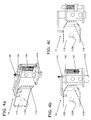
- FIG. 4a shows an indicated holding device 113 with a bent portion 1131.
- the bent section 1131 ensures that this also prevents the unwanted unfolding of the ejection flap 111.
- the web 143 is attached to the transport bracket 141 or may be formed in this. Between a projection of the transport bracket 141 and the retaining profile 140 is the spring 142nd stored clamped. In the holding position of the transport lock 14, as in FIG. 4b shown, the spring 142 pushes the transport bracket 141 via the holding device 113, whereby it is clamped.
- the web 1410 is formed so as to protrude through the container bottom wall 100 so that when pressed in a direction perpendicular to the pin longitudinal axis L, the transport bracket 141 is pressed against the spring 142 in the arrow direction and the transport bracket 141 and the transport lock 14 can be brought into the free position.
- the transport bracket 141 releases the holding device 113.
- the web 1410 in addition to the actuation of the electromagnetic shutter mechanism 13, the web 1410 must be moved from outside the container casing 10 of the collecting container 1 linearly into the container casing 10. If the decoding of the external control unit is correct, by manual movement of the transport bracket 141 perpendicular to the pin longitudinal axis L, the holding device 113 and thus the ejection flap 111 can be released for opening.
- the transport bracket 141 may also be configured electromagnetically unlockable.
- the transport lock 14 is thus arranged and actuated independently of the electromagnetic locking mechanism 13.
- the retainer 113 may be useful to provide the retainer 113 with the bent portion 1130, but this is not necessarily mandatory.
- the design of a forked transport bracket 141 is not necessarily mandatory. As an unwanted unthreading of the pin 131 from the through hole 1130 in opposite direction from the electromagnet 130 should be prevented, a projection on the transport bracket 141 on the side facing away from the electromagnet 130 side of the transport bracket 141 would be sufficient.
- the transport lock 14 completely absorbs the pressure forces when the collecting space 11 is closed and the ejector flap 111 is closed onto the ejection flap 111.
- the electromagnetic shutter mechanism 13 is thus not burdened and spared. If the ejector flap 111 is to be opened, then a user must actuate the transport lock 14. Unintentional opening of the ejection flap 111 can thus be prevented.
Description
Die vorliegende Erfindung beschreibt einen Sammelbehälter eines Aktenentsorgungssystems, umfassend einen Sammelraum mit einer in Entleerungsrichtung geneigt verlaufenden Bodenplatte, eine verschwenkbare Auswurfklappe zur Entleerung von Akten aus dem Sammelraum und einen elektromagnetisch betätigbaren Verschlussmechanismus mit einem Zapfen, welcher mit einer an der Auswurfklappe angeordneten Haltevorrichtung wirkverbindbar ist.The present invention describes a collecting container of a document disposal system, comprising a collecting chamber with a bottom plate inclined in the direction of discharge, a pivotable ejection flap for emptying files from the collecting chamber and an electromagnetically operable locking mechanism with a pin, which is operatively connected to a holding device arranged on the ejection flap.
Entsorgungssysteme, welche das Sammeln, Transportieren und spätere Entsorgen von vertraulichen Akten ermöglichen sind schon seit längerem bekannt. In verschiedenen sensibilisierten Betrieben werden die Akten und anderen Datenträger zentral gesammelt und "kontrolliert" vernichtet, geshreddert und recycliert oder verbrannt. Für dieses Sammeln werden meist besonders gekennzeichnete Behälter verwendet.Disposal systems that enable the collection, transport and later disposal of confidential files have long been known. In various sensitized companies, the files and other data carriers are collected centrally and "controlled" destroyed, shredded and recycled or burned. For this collection mostly labeled containers are used.
In der
Die Bewegungen des Sammelbehälters, sowie die Öffnungs- und Entleerungsvorgänge können mit technischen Mitteln mitverfolgt und archiviert werden. Jeder Sammelbehälter ist dazu mit einer Identifizierungsvorrichtung, einem sogenannten TAG, beispielsweise in Form eines RFID TAGs ausgestattet, welcher eindeutig mit einem bestimmten Sammelbehälter in Verbindung gebracht werden kann. Somit kann protokolliert werden, welcher Sammelbehälter wann und wo in welchen Entsorgungscontainer entleert wurde. Aufgrund der eindeutigen Zuweisung der Sammelbehälter zu Kunden, kann eine präzise Protokollierung stattfinden, welche beispielsweise per GPRS an eine zentrale Datenbank drahtlos gesendet werden kann.The movements of the collection container, as well as the opening and emptying processes can be tracked and archived by technical means. Each collecting container is equipped for this purpose with an identification device, a so-called TAG, for example in the form of an RFID tag, which can be uniquely associated with a specific collecting container. Thus, it can be recorded which sump was emptied when and where in which disposal container. Due to the clear assignment of the collection container to customers, a precise logging can take place, which can be sent for example by GPRS to a central database wirelessly.
Es ist eine Steuereinheit vorgesehen, welche mit dem elektromagnetischen Verschlussmechanismus zusammenwirkt und nach Identifizierung des TAGs, der am Sammelbehälter befestigt ist, und festgestellter Autorisierung die Auswurfklappe zu öffnen vermag. Der elektromagnetische Verschlussmechanismus ist elektronisch codiert und kann nur durch die, die Kodierung kennende Steuereinheit geöffnet werden. Diese Steuereinheit kann am Entsorgungscontainer angebracht oder von einer befugten Person transportiert und betätigt werden.A control unit is provided, which cooperates with the electromagnetic locking mechanism and after identification of the TAG, which is attached to the collecting container, and established authorization is able to open the ejection flap. The electromagnetic shutter mechanism is electronically coded and can only be opened by the control unit knowing the coding. This control unit can be attached to the disposal container or transported and operated by an authorized person.
Der elektromagnetische Verschlussmechanismus ist als Zapfenverschluss ausgebildet und kann kontrolliert unter reproduzierbaren Bedingungen nur durch berechtigte Personen geöffnet werden, wobei die Auswurfklappe verschwenkbar öffenbar ist. Durch Kontaktierung von Elektrokontakten an der Behälterhülle kann der elektromagnetische Verschlussmechanismus von aussen mittels der Steuereinheit betätigt werden.The electromagnetic locking mechanism is designed as a pin lock and can be controlled under reproducible conditions are opened only by authorized persons, the ejector flap is pivotally openable. By contacting electrical contacts on the container shell, the electromagnetic locking mechanism can be actuated from outside by means of the control unit.
Aufgrund der speziellen Gestaltung des Sammelraumes mit einer geneigten Bodenplatte werden die eingeworfenen Akten parallel zur geneigten Bodenplatte des Sammelraumes ausgerichtet gestapelt, was in
Bei der bekannten Lösung gemäss der
Um diese ungewollte Öffnung zu verhindern, kann der Druck auf die Auswurfklappe und den elektromagnetischen Verschlussmechanismus verringert werden, indem beispielsweise die geneigte Bodenplatte weniger steil ausgestaltet wird. Nachteilig ist dann aber dass die Entnahme der gesammelten Akten erschwert ist, da die Akten nicht mehr durch die Schwerkraft aus dem Sammelraum herausrutschen.To prevent this unwanted opening, the pressure on the ejection flap and the electromagnetic shutter mechanism can be reduced, for example, by making the inclined bottom plate less steep. But the disadvantage is that the Removal of the collected files is difficult because the files no longer slip out of the collection space by gravity.
Eine weitere Möglichkeit besteht in der Gestaltung einer Auswurfklappe mit geringerer Angriffsfläche für die Druckkräfte der schräg aufliegenden Akten. Aber auch dabei wird das Herausrutschen der Akten erschwert, indem die Akten teilweise an den Seitenwänden der Behälterhülle verhaken. Dieser Ansatz führt damit nur zu minderwertigen Entleerungsergebnissen.Another possibility is the design of an ejector flap with a lower attack surface for the pressure forces of the obliquely resting files. But even then, the slipping out of the files is made more difficult by the files partially catching on the side walls of the container shell. This approach only leads to inferior emptying results.
Um das ungewollte Öffnen des Zapfenverschlusses und damit des Sammelbehälters zu vermeiden wurde bereits versucht den Zapfen des Zapfenverschlusses mechanisch zu verstärken. Da dieser Zapfen mit einem Elektromagneten elektromagnetisch zusammenwirkt, musste daraufhin auch ein leistungsfähigerer Elektromagnet benutzt werden, der den verstärkten und damit schwereren Zapfen betätigen kann, damit der Verschluss auch wunschgemäss geöffnet werden kann. Zur Betätigung des leistungsfähigeren Elektromagneten muss entsprechend auch eine höhere Leistung eingebracht werden, damit der Elektromagnet den Zapfenverschluss betätigen kann. Damit musste auch die Leistungsabgabe der Steuerungseinheit verändert werden, damit der elektromagnetische Verschlussmechanismus die Auswurfklappe freigeben kann. Dieser Ansatz ist extrem aufwändig und damit nachteilig und führte dazu, dass sich der Zapfenverschluss nicht mehr ungewollt öffnet, aber auch nicht mehr reproduzierbar öffnen lässt, sobald die Magnetkraft nicht exakt den Sollwert erreicht.In order to avoid the unwanted opening of the pin closure and thus the collecting container has already been tried to strengthen the pin of the pin lock mechanically. Since this pin interacts electromagnetically with an electromagnet, then a more powerful electromagnet had to be used, which can operate the reinforced and thus heavier pin, so that the shutter can also be opened as desired. To operate the more powerful electromagnet must also be correspondingly a higher power to be introduced so that the solenoid can actuate the pin lock. Thus, the power output of the control unit had to be changed so that the electromagnetic shutter mechanism can release the ejector. This approach is extremely complex and therefore disadvantageous and meant that the pin lock no longer opens unintentionally, but also can not be opened reproducibly as soon as the magnetic force does not reach exactly the target value.
Die vorliegende Erfindung hat sich zur Aufgabe gestellt einen Sammelbehälter, welcher in einem kontrollierten Entsorgungssystem einsetzbar ist, derart weiterzuentwickeln, dass ein ungewolltes Öffnen des elektromagnetischen Verschlussmechanismus und damit der Auswurfklappe beim Transport des mit Akten beladenen Sammelbehälters verhindert wird.The present invention has set itself the task of a collection container, which in a controlled disposal system can be used to further develop such that accidental opening of the electromagnetic shutter mechanism and thus the ejector flap during transport of the loaded with files collection container is prevented.
Zur Lösung der Aufgabe wird ein Sammelbehälter gemäss Patentanspruch 1 mit einer Transportsicherung vorgeschlagen, umfassend einfache technische Mitteln bei Verwendung von nur wenigen Bauteilen.To solve the problem, a collecting container according to claim 1 is proposed with a transport lock, comprising simple technical means when using only a few components.
Durch die Transportsicherung wird erreicht, dass auf kostenintensive Umbauten des Verschlussmechanismus, die Verwendung eines stärkeren Elektromagneten sowie der Betrieb des Verschlussmechanismus bzw. des Elektromagneten mit höherer Leistung verzichtet werden kann.The transport lock ensures that it is possible to dispense with expensive conversions of the locking mechanism, the use of a stronger electromagnet and the operation of the locking mechanism or the electromagnet with higher power.
Dabei muss ein Benutzer bzw. die Vorrichtung, welche den elektromagnetischen Verschlussmechanismus nach einer Autorisierung auslöst, zusätzlich die Transportsicherung mechanisch von ausserhalb des Sammelbehälters bedienen und die Auswurfklappe einfach gezielt freigeben. Damit ist eine zweite Verriegelungsstufe erreicht, welche den einfachen Zugang zu vertraulichen Dokumenten zusätzlich verhindert.In this case, a user or the device which triggers the electromagnetic locking mechanism after authorization, additionally operate the transport lock mechanically from outside the collecting container and simply release the ejection flap selectively. This achieves a second locking level, which additionally prevents easy access to confidential documents.
Ein bevorzugtes Ausführungsbeispiel des Erfindungsgegenstandes wird nachstehend im Zusammenhang mit den anliegenden Zeichnungen beschrieben.
- Figur 1a
- zeigt eine Schnittansicht eines Sammelbehälters während
- Figur 1b
- eine perspektivische Detailansicht des elektromagnetischen Verschlussmechanismus in Verriegelungsposition mit weggelassener Transportsicherung mit Blick in Richtung der Auswurfklappe zeigt.
Figur 2- zeigt eine perspektivische Ansicht auf den elektromagnetischen Verschlussmechanismus in Verriegelungsposition, wobei der Zapfen mit der Haltevorrichtung der Auswurfklappe zusammenwirkt.
Figur 3- zeigt eine Aufsicht auf die Transportsicherung, wobei der elektromagnetische Verschlussmechanismus in Verriegelungsposition ist.
- Figur 4a
- zeigt eine perspektivische Ansicht der Transportsicherung in Halteposition mit angedeuteter Haltevorrichtung, während
- Figur 4b
- eine Seitenansicht der Transportsicherung gemäss
Figur 4a in Halteposition und - Figur 4c
- eine Seitenansicht der Transportsicherung gemäss
Figur 4a in Freistellposition zeigt. - Figur 5
- zeigt eine Seitenansicht des elektromagnetischen Verschlussmechanismus in Verriegelungsposition und der Transportsicherung in Halteposition, wobei die Bewegungsmöglichkeit der Transportsicherung mit einem Pfeil angedeutet ist.
- Figur 6
- zeigt den bekannten Stand der Technik eines Sammelbehälters mit geschlossener und geöffneter Auswurfklappe in einer Schnittansicht.
- FIG. 1a
- shows a sectional view of a collecting container during
- FIG. 1b
- a detailed perspective view of the electromagnetic locking mechanism in the locked position with omitted Transport lock with view towards the ejection flap shows.
- FIG. 2
- shows a perspective view of the electromagnetic locking mechanism in the locking position, wherein the pin cooperates with the holding device of the ejection flap.
- FIG. 3
- shows a plan view of the transport lock, wherein the electromagnetic locking mechanism is in the locked position.
- FIG. 4a
- shows a perspective view of the transport lock in holding position with indicated holding device, while
- FIG. 4b
- a side view of the transport lock according
FIG. 4a in stop position and - Figure 4c
- a side view of the transport lock according
FIG. 4a in free position shows. - FIG. 5
- shows a side view of the electromagnetic locking mechanism in the locked position and the transport lock in holding position, the possibility of movement of the transport lock is indicated by an arrow.
- FIG. 6
- shows the known prior art of a collecting container with closed and opened discharge flap in a sectional view.
Im Folgenden wird ein Sammelbehälter 1 beschrieben, welcher zur Verwendung eines Aktenentsorgungssystems wie in der Beschreibungseinleitung offenbart, einsetzbar ist. Das Aktenentsorgungssystem stellt ein geschlossenes System dar, welches nach Einwurf zu entsorgender Akten in den Sammelbehälter 1 den Zugang zu den Akten durch Unbefugte verhindert. Der Inhalt des Sammelbehälters 1 wird in einen Entsorgungscontainer entleert und der gesammelte Inhalt des Entsorgungscontainers anschliessend geschreddert, wobei der Zugang zu den zu entsorgenden Akten zu jeder Zeit unterbunden ist.In the following, a collection container 1 will be described which can be used for the use of a document disposal system as disclosed in the introduction to the description. The document disposal system represents a closed system, which prevents access to the files by unauthorized persons after throwing the files to be disposed of into the collection container 1. The contents of the collection container 1 is emptied into a disposal container and then shredded the collected contents of the disposal container, the access to the files to be disposed of is prevented at any time.
Der Sammelbehälter 1 umfasst eine Behälterhülle 10 bestehend aus einer Behälterbodenwand 100 und anderen Behälterwänden, die einen Sammelraum 11 umschliessen, in welchem Akten gesammelt werden können. Der Sammelbehälter 1 weist eine Einfüllseite für Akten mit einem Einwurf 12 auf. Der Einwurf 12 ist mit einem Einwurfscharnier 120 ausgestaltet und dadurch schwenkbar gestaltet. Eine Schikane innerhalb des Sammelraumes 11 im Bereich des Einwurfes 12 verhindert, dass Unbefugte eingeworfene Akten durch den Einwurf 12 dem Sammelbehälter unerlaubt entnehmen können.The collecting container 1 comprises a
Der Sammelbehälter 1 weist eine dem Boden zugewandte Auswurfseite auf. An einer Behälterwand ist eine Auswurfklappe 111 angeordnet, welche an einem Auswurfklappenscharnier 112 schwenkbar um eine Schwenkachse gelagert ist. Im aufgeschwenkten Zustand der Auswurfklappe 111 können gesammelte Akten aus dem Sammelraum 11 abgeführt werden. Um die Entnahme von Akten aus dem Sammelraum 11 zu erleichtern ist der Sammelraum 11 mit einer geneigten Bodenplatte 110 ausgestattet. Auf dieser geneigten Bodenplatte 110, die rampenartig ausgestaltet ist, werden eingeführte Akten in einer schrägen Ausrichtung gelagert. Bei geöffneter Auswurfklappe und vertikaler Ausrichtung des Sammelbehälters 1 rutschen die Akten ohne weiteres aus dem Sammelraum heraus.The collecting container 1 has a discharge side facing the bottom. On a container wall, an
Um den Sammelbehälter 1 einfach transportieren zu können sind an der Unterseite Räder 2 und an der Einfüllseite ein Handlauf 3 angeordnet. Damit kann der Sammelbehälter 1 von einer Sammelposition zu dem Entsorgungscontainer bewegt werden, wobei der Entsorgungscontainer die gesammelten Akten des Sammelbehälters 1 übernimmt.In order to be able to easily transport the collecting container 1, a
Jeder Sammelbehälter 1 ist mit einer Identifizierungsvorrichtung, einem Datenträger oder sogenannten TAG 102, beispielsweise in Form eines RFID TAGs ausgestattet, welcher eindeutig mit einem bestimmten Sammelbehälter 1 in Verbindung gebracht werden kann. Durch den Datenträger 102 können alle Bewegungen und Öffnungsvorgänge protokolliert und gespeichert und später ausgelesen werden.Each collecting container 1 is equipped with an identification device, a data carrier or so-called
Damit nach erfolgtem Einwurf nur noch befugte Personen Zugang zu den zu entsorgenden Akten haben, ist ein gesicherter elektromagnetisch betätigbarer Verschlussmechanismus 13 unterhalb der geneigten Bodenplatte 110 angeordnet. Der elektromagnetische Verschlussmechanismus 13 ist mit einer Haltevorrichtung 113 (wie in
Der elektromagnetisch betätigbare Verschlussmechanismus 13 umfasst einen Elektromagneten 130, einen Zapfen 131 und eine interne Steuereinheit 132. Dieser elektromagnetische Verschlussmechanismus 13 ist an der Innenfläche der Behälterbodenwand 100 befestigt. Hier ist der elektromagnetische Verschlussmechanismus 13 beispielsweise auf einem Montageblech 135 angeordnet, welches wiederum auf der Behälterbodenwand 100 befestigt ist. Der Elektromagnet 130 ist mit einem Magnethalter 1301 auf dem Montageblech 135 befestigt.The electromagnetically
An der Behälterhülle 10 sind nicht gezeigte Elektrokontakte angeordnet, welche zur internen Steuereinheit 132 führen. Eine externe Öffnungselektronik kann über die ausserhalb der Behälterhülle angeordneten Elektrokontakte an die interne Steuereinheit 132 angeschlossen werden. Durch die interne Steuereinheit 132 ist der Elektromagnet 130 über elektrische Zuleitungen 134 antreibbar. Der Entladestrom eines aufgeladenen Kondensators 133 wird hier zum Betrieb des Elektromagneten 130 verwendet.Arranged on the
Der Elektromagnet 130 ist mit dem Zapfen 131 derart wirkverbunden, dass der Zapfen 131 etwa parallel zur Behälterbodenwand 100 in Richtung der Zapfenlängsachse L in Richtung eines Durchgangsloches 1130 der Haltevorrichtung 113 bewegbar ist. Der Zapfen 131 ist dabei mindestens teilweise durch das Durchgangsloch 1130 der Haltevorrichtung 113 durchführbar. Im geschlossenen Zustand der Auswurfklappe 111 ragt der Zapfen 131 durch das Durchgangsloch 1130 vollständig hindurch. In dieser Verriegelungsposition des elektromagnetischen Verschlussmechanismus 13 ist die Auswurfklappe 111 durch den Verschlussmechanismus 13 im Bereich der Behälterbodenwand 100 lösbar gesichert befestigt ist.The
Zum Öffnen der Auswurfklappe 111 muss der elektromagnetische Verschlussmechanismus 13 in die Entriegelungsposition gebracht werden. Dazu muss die externe Steuereinheit über die Elektrokontakte an die interne Steuereinheit 132 angeschlossen werden. Die interne Steuereinheit 132 ist mit einer elektronischen Kodierung versehen, welche den elektromagnetischen Verschlussmechanismus nur öffnet, wenn die externe Steuereinheit die korrekte elektronische Dekodierung zur Öffnung des jeweiligen Sammelbehälters 1 kennt. Sobald die Dekodierung stattgefunden hat, wird der Kondensator 133 aufgeladen. Durch die Entladung des Kondensators 133 über die elektrischen Zuleitungen 134 wird der Elektromagnet 130 betätigt, welcher den Zapfen 131 in Richtung der Zapfenlängsachse L aus dem Durchgangsloch 1130 der Haltevorrichtung 113 herauszieht, wodurch die Auswurfklappe 111 freigegeben wird. Die Entleerung findet dann aufgrund der Schwerkraft automatisch statt. Nach der Entleerung kann die Auswurfklappe 111 wieder zugedrückt werden, wobei der, wieder in der Verriegelungsposition befindliche Zapfen 131 in das Durchgangsloch 1130 der ösenförmig ausgestalteten Haltevorrichtung 113 gleitet. Somit ist die Auswurfklappe 111 des Sammelbehälters 1 wieder verschlossen und der elektromagnetische Verschlussmechanismus wieder in der Verriegelungsposition.To open the
Da bei befülltem Sammelbehälter 1 durch die Lagerung der Akten auf der geneigten Bodenplatte 110 ein hoher Druck auf die grossflächig ausgeführte Auswurfklappe 111 wirkt, wirken entsprechend grosse Kräfte auf den Zapfen 131 des elektromagnetischen Verschlussmechanismus 13. Damit der Zapfen 131 gut in das Durchgangsloch 1130 der Haltevorrichtung 113 beim Verriegeln gleiten kann, ist der Zapfen 131 mehrteilig und teilweise flexibel ausgestaltet.Since a high pressure on the large-
In
Die Transportsicherung 14 umfasst ein fest indirekt oder direkt auf der Behälterbodenwand 100 befestigtes Halteprofil 140. In diesem Halteprofil 140 ist eine Transporthalterung 141 bewegbar angeordnet gelagert. Die lineare Bewegbarkeit des Halteprofils 140 erfolgt gegen eine Feder 142. Die Feder 142 ist als Druckfeder 142 ausgeführt und zwingt die Transporthalterung 141 aufgrund der Federkraft in die Halteposition. Die Transporthalterung 141 weist einen Steg 1410 auf. Die Transporthalterung 141 ist derart gelagert, dass der Steg 1410 bei Stellung der Transportsicherung 14 in Halteposition, aus der Behälterhülle 10, insbesondere aus der Behälterbodenwand 100 herausragt.The
Die Transporthalterung 141 ist gegabelt ausgestaltet und verhindert in der Halteposition bei eingeführter Haltevorrichtung 113 eine Bewegung der Haltevorrichtung 113 in Richtung der Zapfenlängsachse L. Die Haltevorrichtung 113 ist von der Transporthalterung 141 teilweise umschlossen gehalten, wobei der Zapfen 131 und der gesamte elektromagnetische Verschlussmechanismus 13 uneingeschränkt betreibbar ist.The
In
Die perspektivische Ansicht
Der Steg 143 ist an der Transporthalterung 141 befestigt oder kann in diese angeformt sein. Zwischen einem Vorsprung der Transporthalterung 141 und dem Halteprofil 140 ist die Feder 142 einspannbar gelagert. In der Halteposition der Transportsicherung 14, wie in
Der Steg 1410 ist so durch die Behälterbodenwand 100 hindurchragend ausgebildet, dass beim Drücken in eine Richtung senkrecht zur Zapfenlängsachse L die Transporthalterung 141 gegen die Feder 142 in Pfeilrichtung gedrückt wird und die Transporthalterung 141 bzw. die Transportsicherung 14 in Freistellposition bringbar ist. Die Transporthalterung 141 gibt dabei die Haltevorrichtung 113 frei.The
Um also die Auswurfklappe 111 zu öffnen, muss neben der Betätigung des elektromagnetischen Verschlussmechanismus 13 der Steg 1410 von ausserhalb der Behälterhülle 10 des Sammelbehälters 1 linear in die Behälterhülle 10 hineinbewegt werden. Wenn die Dekodierung der externen Steuereinheit korrekt ist, kann durch manuelle Bewegung der Transporthalterung 141 senkrecht zur Zapfenlängsachse L die Haltevorrichtung 113 und damit die Auswurfklappe 111 zur Öffnung freigegeben werden. Neben einer rein mechanischen Entriegelung der Transportsicherung 14 kann die Transporthalterung 141 auch elektromagnetisch entriegelbar ausgestaltet sein.Thus, in order to open the
Die Transportsicherung 14 ist damit unabhängig vom elektromagnetischen Verschlussmechanismus 13 angeordnet und betätigbar.The
Wie oben erläutert kann es nützlich sein, die Haltevorrichtung 113 mit dem gebogenen Abschnitt 1130 auszustatten, dies ist aber nicht unbedingt zwingend. Auch die Ausgestaltung einer gegabelten Transporthalterung 141 ist nicht unbedingt zwingend. Da ein ungewünschtes Ausfädeln des Zapfens 131 aus dem Durchgangsloch 1130 in vom Elektromagneten 130 entgegen gesetzte Richtung verhindert werden soll, würde ein Vorsprung an der Transporthalterung 141 auf der dem Elektromagneten 130 abgewandten Seite der Transporthalterung 141 ausreichen.As explained above, it may be useful to provide the
Die Transportsicherung 14 nimmt die Druckkräfte bei befülltem Sammelraum 11 und geschlossener Auswurfklappe 111 auf die Auswurfklappe 111 vollständig auf. Der elektromagnetische Verschlussmechanismus 13 wird damit nicht belastet und geschont. Wenn die Auswurfklappe 111 geöffnet werden soll, dann muss ein Benutzer die Transportsicherung 14 betätigen. Ein ungewolltes Öffnen der Auswurfklappe 111 kann damit verhindert werden.The
- 11
- SammelbehälterClippings
- 22
- Radwheel
- 33
- Handlaufhandrail
- 1010
-
Behälterhülle
100 Behälterbodenwand
102 Datenträger (TAG)container shell
100 container bottom wall
102 data carriers (TAG) - 1111
-
Sammelraum
110 geneigte Bodenplatte
111 Auswurfklappe
112 Auswurfklappenscharnier
113 Haltevorrichtung (Klappenöse)
1130 Durchgangsloch
1131 gebogener Abschnittplenum
110 inclined floor plate
111 ejector flap
112 ejector flap hinge
113 holding device (flap eyelet)
1130 through hole
1131 curved section - 1212
-
Einwurf
120 Einwurfscharnierobjection
120 insertion hinge - 1313
-
elektromagnetischer Verschlussmechanismus (Zapfenverschluss)
130 Elektromagnet
1301 Magnethalter
131 Zapfen
132 interne Steuereinheit mit Kodierung
133 Kondensator
134 elektrische Zuleitung
135 Montageblech
L Zapfenlängsachseelectromagnetic locking mechanism (pin lock)
130 electromagnet
1301 magnet holder
131 pegs
132 internal control unit with coding
133 capacitor
134 electrical supply line
135 mounting plate
L journal longitudinal axis - 1414
-
Transportsicherung
140 Halteprofil
141 Transporthalterung (gegabelt)
1410 Steg
142 Feder (Druckfeder)transport safety
140 holding profile
141 Transport bracket (forked)
1410 footbridge
142 spring (compression spring)
Claims (9)
- Collection container (1) of a document disposal system, comprising a collection chamber (11) having a base plate (110) extending in an inclined manner in an emptying direction, a pivotable ejection flap (111) for emptying documents from the collection chamber (11) and
an electromagnetically actuatable closure mechanism (13) with a pin (131) which is able to be operatively connected to a retaining device (113) arranged on the ejection flap (111),
characterised in that
a transport securing device (14) is able to be operatively connected to the retaining device (113) of the ejection flap (111), the transport securing device (14) entirely absorbing the compressive forces on the ejection flap (111), when the collection chamber (11) is full and the ejection flap (111) is closed, and thereby relieving the electromagnetically actuatable closure mechanism (13) of said forces
and the transport securing device (14) protrudes at least partially from the container cover (10) and thus is able to be mechanically unlocked from outside, in addition to the electromagnetic unlocking of the pin (131) from the retaining device (113), whereby the ejection flap (111) is only then able to be released. - Collection container according to Claim 1, the transport securing device (14) comprising a retaining profile (140) fastened to the container base wall (100) and a clamping structure (141) which is able to be moved in the retaining profile (140) against a spring (142).
- Collection container according to Claim 1, the clamping structure (141) protruding at least partially from the container cover (10).
- Collection container according to Claim 2, the spring (142) being a compression spring (142).
- Collection container according to Claim 2, the clamping structure (141) being movably arranged in a direction perpendicular to the longitudinal axis of the pin (L).
- Collection container according to Claim 2, the clamping structure (141) comprising a projection (143), which protrudes at least partially through the container base wall (100) and permits a displacement of the clamping structure (141) from outside the collection chamber (11).
- Collection container according to one of the preceding claims, the retaining device (113) of the ejection flap (111) comprising a through-hole (1130) and a curved portion (1131).
- Collection container according to one of the preceding claims, the electromagnetic closure mechanism (13) and the retaining profile (140) being unreleasably fastened to the container base wall (100) inside the collection container (1).
- Collection container according to one of the preceding claims, the clamping structure (141) of the transport securing device (14) being able to be unlocked purely mechanically or electromagnetically.
Applications Claiming Priority (1)
| Application Number | Priority Date | Filing Date | Title |
|---|---|---|---|
| CH01635/11A CH705597A1 (en) | 2011-10-06 | 2011-10-06 | Collecting a document disposal system with a transport lock. |
Publications (2)
| Publication Number | Publication Date |
|---|---|
| EP2578517A1 EP2578517A1 (en) | 2013-04-10 |
| EP2578517B1 true EP2578517B1 (en) | 2014-03-12 |
Family
ID=46420023
Family Applications (1)
| Application Number | Title | Priority Date | Filing Date |
|---|---|---|---|
| EP20120175573 Not-in-force EP2578517B1 (en) | 2011-10-06 | 2012-07-09 | Transport fixture of a collection container of a disposal system |
Country Status (2)
| Country | Link |
|---|---|
| EP (1) | EP2578517B1 (en) |
| CH (1) | CH705597A1 (en) |
Families Citing this family (2)
| Publication number | Priority date | Publication date | Assignee | Title |
|---|---|---|---|---|
| GB2515832B (en) * | 2013-07-05 | 2015-12-30 | Bag It Up Ltd | Receptacle |
| EP2937298A1 (en) | 2014-04-24 | 2015-10-28 | Tesmapri SpA | Apparatus to manage containers |
Family Cites Families (3)
| Publication number | Priority date | Publication date | Assignee | Title |
|---|---|---|---|---|
| US3141609A (en) * | 1962-09-17 | 1964-07-21 | Rodan Ind Inc | Disposal container |
| ATE384675T1 (en) * | 2002-02-21 | 2008-02-15 | Hubtech Ag | COLLECT, TRANSPORT AND SECURE DISPOSAL OF DOCUMENTS AND DATA CARRIERS |
| DE102008028068B4 (en) * | 2008-06-12 | 2015-06-18 | Gantner Electronic Gmbh | Electromechanical locking device |
-
2011
- 2011-10-06 CH CH01635/11A patent/CH705597A1/en not_active Application Discontinuation
-
2012
- 2012-07-09 EP EP20120175573 patent/EP2578517B1/en not_active Not-in-force
Also Published As
| Publication number | Publication date |
|---|---|
| CH705597A1 (en) | 2013-04-15 |
| EP2578517A1 (en) | 2013-04-10 |
Similar Documents
| Publication | Publication Date | Title |
|---|---|---|
| EP0974719B1 (en) | Lock, in particular for a locking system | |
| DE4428427C2 (en) | Locking device for a waste container | |
| DE112009000326T5 (en) | lock mechanism | |
| EP2574573B1 (en) | Electromagnetic closure mechanism of a collection container of a disposal system | |
| EP2385505A1 (en) | Device for holding bank notes, security system with such a device and method | |
| EP2578517B1 (en) | Transport fixture of a collection container of a disposal system | |
| DE102011086423A1 (en) | Locking system for a drawer block or for a carrier system | |
| DE102008057034B4 (en) | Device for opening a door | |
| DE102009037459A1 (en) | Container for holding notes of value and method for closing a container comprising a housing part and a lid for holding notes of value | |
| EP2862485A1 (en) | Device for delivering and/or collecting goods | |
| DE102013224369A1 (en) | Package box with optimized locking | |
| DE102011000294A1 (en) | Method for controlling the transport of safebags | |
| EP1789646A1 (en) | Security chest security system and security complex | |
| WO2003070606A1 (en) | Collection, transport, and secure disposal of documents and data carriers | |
| DE102008064636B4 (en) | Storage machine with child safety lock | |
| EP2293256A2 (en) | Access device, in particular for a mobile or stationary waste removal device | |
| DE102017117826A1 (en) | MATERIAL VEHICLE AND METHOD FOR COMMUNICATING WORKING MATERIAL TO A MACHINE | |
| DE102011014960A1 (en) | Safety system for a collection system and collection system | |
| DE102017208050A1 (en) | System and method for delivering and / or picking up packages | |
| EP3093072B1 (en) | Method for securing documents stored in lockable cartridges of document shredders against unauthorized access and device for carrying out the method | |
| EP0929877A1 (en) | Banknote container for cash dispenser | |
| EP0977928B1 (en) | Electrically controlled lock for a safe | |
| DE19950328C2 (en) | Method and device for powerless unlocking of a locking device | |
| DE10028803A1 (en) | System of lockable individual containers and a collecting container for emptying such lockable individual containers | |
| EP1035491A2 (en) | Chip card reader |
Legal Events
| Date | Code | Title | Description |
|---|---|---|---|
| PUAI | Public reference made under article 153(3) epc to a published international application that has entered the european phase |
Free format text: ORIGINAL CODE: 0009012 |
|
| AK | Designated contracting states |
Kind code of ref document: A1 Designated state(s): AL AT BE BG CH CY CZ DE DK EE ES FI FR GB GR HR HU IE IS IT LI LT LU LV MC MK MT NL NO PL PT RO RS SE SI SK SM TR |
|
| AX | Request for extension of the european patent |
Extension state: BA ME |
|
| GRAP | Despatch of communication of intention to grant a patent |
Free format text: ORIGINAL CODE: EPIDOSNIGR1 |
|
| 17P | Request for examination filed |
Effective date: 20130830 |
|
| RBV | Designated contracting states (corrected) |
Designated state(s): AL AT BE BG CH CY CZ DE DK EE ES FI FR GB GR HR HU IE IS IT LI LT LU LV MC MK MT NL NO PL PT RO RS SE SI SK SM TR |
|
| RIC1 | Information provided on ipc code assigned before grant |
Ipc: B65F 1/14 20060101ALI20130924BHEP Ipc: B65F 1/12 20060101ALI20130924BHEP Ipc: B65F 1/10 20060101AFI20130924BHEP |
|
| INTG | Intention to grant announced |
Effective date: 20131011 |
|
| RAP1 | Party data changed (applicant data changed or rights of an application transferred) |
Owner name: HUBTECH AG |
|
| RIN1 | Information on inventor provided before grant (corrected) |
Inventor name: HUBER, HANS JOERG |
|
| GRAS | Grant fee paid |
Free format text: ORIGINAL CODE: EPIDOSNIGR3 |
|
| GRAA | (expected) grant |
Free format text: ORIGINAL CODE: 0009210 |
|
| AK | Designated contracting states |
Kind code of ref document: B1 Designated state(s): AL AT BE BG CH CY CZ DE DK EE ES FI FR GB GR HR HU IE IS IT LI LT LU LV MC MK MT NL NO PL PT RO RS SE SI SK SM TR |
|
| REG | Reference to a national code |
Ref country code: GB Ref legal event code: FG4D Free format text: NOT ENGLISH |
|
| REG | Reference to a national code |
Ref country code: CH Ref legal event code: EP |
|
| REG | Reference to a national code |
Ref country code: AT Ref legal event code: REF Ref document number: 656134 Country of ref document: AT Kind code of ref document: T Effective date: 20140315 |
|
| REG | Reference to a national code |
Ref country code: IE Ref legal event code: FG4D Free format text: LANGUAGE OF EP DOCUMENT: GERMAN |
|
| REG | Reference to a national code |
Ref country code: DE Ref legal event code: R096 Ref document number: 502012000417 Country of ref document: DE Effective date: 20140424 |
|
| REG | Reference to a national code |
Ref country code: CH Ref legal event code: NV Representative=s name: SCHNEIDER FELDMANN AG PATENT- UND MARKENANWAEL, CH |
|
| REG | Reference to a national code |
Ref country code: NL Ref legal event code: VDEP Effective date: 20140312 |
|
| PG25 | Lapsed in a contracting state [announced via postgrant information from national office to epo] |
Ref country code: LT Free format text: LAPSE BECAUSE OF FAILURE TO SUBMIT A TRANSLATION OF THE DESCRIPTION OR TO PAY THE FEE WITHIN THE PRESCRIBED TIME-LIMIT Effective date: 20140312 Ref country code: NO Free format text: LAPSE BECAUSE OF FAILURE TO SUBMIT A TRANSLATION OF THE DESCRIPTION OR TO PAY THE FEE WITHIN THE PRESCRIBED TIME-LIMIT Effective date: 20140612 |
|
| REG | Reference to a national code |
Ref country code: LT Ref legal event code: MG4D |
|
| PG25 | Lapsed in a contracting state [announced via postgrant information from national office to epo] |
Ref country code: CY Free format text: LAPSE BECAUSE OF FAILURE TO SUBMIT A TRANSLATION OF THE DESCRIPTION OR TO PAY THE FEE WITHIN THE PRESCRIBED TIME-LIMIT Effective date: 20140312 Ref country code: SE Free format text: LAPSE BECAUSE OF FAILURE TO SUBMIT A TRANSLATION OF THE DESCRIPTION OR TO PAY THE FEE WITHIN THE PRESCRIBED TIME-LIMIT Effective date: 20140312 Ref country code: FI Free format text: LAPSE BECAUSE OF FAILURE TO SUBMIT A TRANSLATION OF THE DESCRIPTION OR TO PAY THE FEE WITHIN THE PRESCRIBED TIME-LIMIT Effective date: 20140312 |
|
| PG25 | Lapsed in a contracting state [announced via postgrant information from national office to epo] |
Ref country code: RS Free format text: LAPSE BECAUSE OF FAILURE TO SUBMIT A TRANSLATION OF THE DESCRIPTION OR TO PAY THE FEE WITHIN THE PRESCRIBED TIME-LIMIT Effective date: 20140312 Ref country code: LV Free format text: LAPSE BECAUSE OF FAILURE TO SUBMIT A TRANSLATION OF THE DESCRIPTION OR TO PAY THE FEE WITHIN THE PRESCRIBED TIME-LIMIT Effective date: 20140312 Ref country code: HR Free format text: LAPSE BECAUSE OF FAILURE TO SUBMIT A TRANSLATION OF THE DESCRIPTION OR TO PAY THE FEE WITHIN THE PRESCRIBED TIME-LIMIT Effective date: 20140312 |
|
| PG25 | Lapsed in a contracting state [announced via postgrant information from national office to epo] |
Ref country code: CZ Free format text: LAPSE BECAUSE OF FAILURE TO SUBMIT A TRANSLATION OF THE DESCRIPTION OR TO PAY THE FEE WITHIN THE PRESCRIBED TIME-LIMIT Effective date: 20140312 Ref country code: NL Free format text: LAPSE BECAUSE OF FAILURE TO SUBMIT A TRANSLATION OF THE DESCRIPTION OR TO PAY THE FEE WITHIN THE PRESCRIBED TIME-LIMIT Effective date: 20140312 Ref country code: RO Free format text: LAPSE BECAUSE OF FAILURE TO SUBMIT A TRANSLATION OF THE DESCRIPTION OR TO PAY THE FEE WITHIN THE PRESCRIBED TIME-LIMIT Effective date: 20140312 Ref country code: EE Free format text: LAPSE BECAUSE OF FAILURE TO SUBMIT A TRANSLATION OF THE DESCRIPTION OR TO PAY THE FEE WITHIN THE PRESCRIBED TIME-LIMIT Effective date: 20140312 Ref country code: IS Free format text: LAPSE BECAUSE OF FAILURE TO SUBMIT A TRANSLATION OF THE DESCRIPTION OR TO PAY THE FEE WITHIN THE PRESCRIBED TIME-LIMIT Effective date: 20140712 Ref country code: BG Free format text: LAPSE BECAUSE OF FAILURE TO SUBMIT A TRANSLATION OF THE DESCRIPTION OR TO PAY THE FEE WITHIN THE PRESCRIBED TIME-LIMIT Effective date: 20140612 |
|
| PG25 | Lapsed in a contracting state [announced via postgrant information from national office to epo] |
Ref country code: ES Free format text: LAPSE BECAUSE OF FAILURE TO SUBMIT A TRANSLATION OF THE DESCRIPTION OR TO PAY THE FEE WITHIN THE PRESCRIBED TIME-LIMIT Effective date: 20140312 Ref country code: PL Free format text: LAPSE BECAUSE OF FAILURE TO SUBMIT A TRANSLATION OF THE DESCRIPTION OR TO PAY THE FEE WITHIN THE PRESCRIBED TIME-LIMIT Effective date: 20140312 Ref country code: SK Free format text: LAPSE BECAUSE OF FAILURE TO SUBMIT A TRANSLATION OF THE DESCRIPTION OR TO PAY THE FEE WITHIN THE PRESCRIBED TIME-LIMIT Effective date: 20140312 |
|
| REG | Reference to a national code |
Ref country code: DE Ref legal event code: R097 Ref document number: 502012000417 Country of ref document: DE |
|
| PG25 | Lapsed in a contracting state [announced via postgrant information from national office to epo] |
Ref country code: PT Free format text: LAPSE BECAUSE OF FAILURE TO SUBMIT A TRANSLATION OF THE DESCRIPTION OR TO PAY THE FEE WITHIN THE PRESCRIBED TIME-LIMIT Effective date: 20140714 |
|
| PLBE | No opposition filed within time limit |
Free format text: ORIGINAL CODE: 0009261 |
|
| STAA | Information on the status of an ep patent application or granted ep patent |
Free format text: STATUS: NO OPPOSITION FILED WITHIN TIME LIMIT |
|
| PG25 | Lapsed in a contracting state [announced via postgrant information from national office to epo] |
Ref country code: DK Free format text: LAPSE BECAUSE OF FAILURE TO SUBMIT A TRANSLATION OF THE DESCRIPTION OR TO PAY THE FEE WITHIN THE PRESCRIBED TIME-LIMIT Effective date: 20140312 |
|
| 26N | No opposition filed |
Effective date: 20141215 |
|
| PG25 | Lapsed in a contracting state [announced via postgrant information from national office to epo] |
Ref country code: RS Free format text: LAPSE BECAUSE OF FAILURE TO SUBMIT A TRANSLATION OF THE DESCRIPTION OR TO PAY THE FEE WITHIN THE PRESCRIBED TIME-LIMIT Effective date: 20140903 Ref country code: LU Free format text: LAPSE BECAUSE OF FAILURE TO SUBMIT A TRANSLATION OF THE DESCRIPTION OR TO PAY THE FEE WITHIN THE PRESCRIBED TIME-LIMIT Effective date: 20140709 |
|
| REG | Reference to a national code |
Ref country code: DE Ref legal event code: R097 Ref document number: 502012000417 Country of ref document: DE Effective date: 20141215 |
|
| PG25 | Lapsed in a contracting state [announced via postgrant information from national office to epo] |
Ref country code: IT Free format text: LAPSE BECAUSE OF FAILURE TO SUBMIT A TRANSLATION OF THE DESCRIPTION OR TO PAY THE FEE WITHIN THE PRESCRIBED TIME-LIMIT Effective date: 20140312 |
|
| REG | Reference to a national code |
Ref country code: IE Ref legal event code: MM4A |
|
| REG | Reference to a national code |
Ref country code: FR Ref legal event code: ST Effective date: 20150331 |
|
| PG25 | Lapsed in a contracting state [announced via postgrant information from national office to epo] |
Ref country code: FR Free format text: LAPSE BECAUSE OF NON-PAYMENT OF DUE FEES Effective date: 20140731 |
|
| PG25 | Lapsed in a contracting state [announced via postgrant information from national office to epo] |
Ref country code: SI Free format text: LAPSE BECAUSE OF FAILURE TO SUBMIT A TRANSLATION OF THE DESCRIPTION OR TO PAY THE FEE WITHIN THE PRESCRIBED TIME-LIMIT Effective date: 20140312 |
|
| PG25 | Lapsed in a contracting state [announced via postgrant information from national office to epo] |
Ref country code: IE Free format text: LAPSE BECAUSE OF NON-PAYMENT OF DUE FEES Effective date: 20140709 |
|
| PG25 | Lapsed in a contracting state [announced via postgrant information from national office to epo] |
Ref country code: MC Free format text: LAPSE BECAUSE OF FAILURE TO SUBMIT A TRANSLATION OF THE DESCRIPTION OR TO PAY THE FEE WITHIN THE PRESCRIBED TIME-LIMIT Effective date: 20140312 Ref country code: SM Free format text: LAPSE BECAUSE OF FAILURE TO SUBMIT A TRANSLATION OF THE DESCRIPTION OR TO PAY THE FEE WITHIN THE PRESCRIBED TIME-LIMIT Effective date: 20140312 |
|
| PG25 | Lapsed in a contracting state [announced via postgrant information from national office to epo] |
Ref country code: GR Free format text: LAPSE BECAUSE OF FAILURE TO SUBMIT A TRANSLATION OF THE DESCRIPTION OR TO PAY THE FEE WITHIN THE PRESCRIBED TIME-LIMIT Effective date: 20140613 Ref country code: MT Free format text: LAPSE BECAUSE OF FAILURE TO SUBMIT A TRANSLATION OF THE DESCRIPTION OR TO PAY THE FEE WITHIN THE PRESCRIBED TIME-LIMIT Effective date: 20140312 |
|
| PG25 | Lapsed in a contracting state [announced via postgrant information from national office to epo] |
Ref country code: BE Free format text: LAPSE BECAUSE OF FAILURE TO SUBMIT A TRANSLATION OF THE DESCRIPTION OR TO PAY THE FEE WITHIN THE PRESCRIBED TIME-LIMIT Effective date: 20140731 Ref country code: HU Free format text: LAPSE BECAUSE OF FAILURE TO SUBMIT A TRANSLATION OF THE DESCRIPTION OR TO PAY THE FEE WITHIN THE PRESCRIBED TIME-LIMIT; INVALID AB INITIO Effective date: 20120709 Ref country code: TR Free format text: LAPSE BECAUSE OF FAILURE TO SUBMIT A TRANSLATION OF THE DESCRIPTION OR TO PAY THE FEE WITHIN THE PRESCRIBED TIME-LIMIT Effective date: 20140312 |
|
| GBPC | Gb: european patent ceased through non-payment of renewal fee |
Effective date: 20160709 |
|
| PG25 | Lapsed in a contracting state [announced via postgrant information from national office to epo] |
Ref country code: GB Free format text: LAPSE BECAUSE OF NON-PAYMENT OF DUE FEES Effective date: 20160709 |
|
| PGFP | Annual fee paid to national office [announced via postgrant information from national office to epo] |
Ref country code: DE Payment date: 20170705 Year of fee payment: 6 |
|
| PGFP | Annual fee paid to national office [announced via postgrant information from national office to epo] |
Ref country code: CH Payment date: 20171030 Year of fee payment: 6 |
|
| PG25 | Lapsed in a contracting state [announced via postgrant information from national office to epo] |
Ref country code: MK Free format text: LAPSE BECAUSE OF FAILURE TO SUBMIT A TRANSLATION OF THE DESCRIPTION OR TO PAY THE FEE WITHIN THE PRESCRIBED TIME-LIMIT Effective date: 20140312 |
|
| REG | Reference to a national code |
Ref country code: AT Ref legal event code: MM01 Ref document number: 656134 Country of ref document: AT Kind code of ref document: T Effective date: 20170709 |
|
| PG25 | Lapsed in a contracting state [announced via postgrant information from national office to epo] |
Ref country code: AL Free format text: LAPSE BECAUSE OF FAILURE TO SUBMIT A TRANSLATION OF THE DESCRIPTION OR TO PAY THE FEE WITHIN THE PRESCRIBED TIME-LIMIT Effective date: 20140312 |
|
| PG25 | Lapsed in a contracting state [announced via postgrant information from national office to epo] |
Ref country code: AT Free format text: LAPSE BECAUSE OF NON-PAYMENT OF DUE FEES Effective date: 20170709 |
|
| REG | Reference to a national code |
Ref country code: DE Ref legal event code: R119 Ref document number: 502012000417 Country of ref document: DE |
|
| REG | Reference to a national code |
Ref country code: CH Ref legal event code: PL |
|
| PG25 | Lapsed in a contracting state [announced via postgrant information from national office to epo] |
Ref country code: DE Free format text: LAPSE BECAUSE OF NON-PAYMENT OF DUE FEES Effective date: 20190201 Ref country code: LI Free format text: LAPSE BECAUSE OF NON-PAYMENT OF DUE FEES Effective date: 20180731 Ref country code: CH Free format text: LAPSE BECAUSE OF NON-PAYMENT OF DUE FEES Effective date: 20180731 |