EP2578486A1 - Bicycle crank assembly - Google Patents
Bicycle crank assembly Download PDFInfo
- Publication number
- EP2578486A1 EP2578486A1 EP12178460.7A EP12178460A EP2578486A1 EP 2578486 A1 EP2578486 A1 EP 2578486A1 EP 12178460 A EP12178460 A EP 12178460A EP 2578486 A1 EP2578486 A1 EP 2578486A1
- Authority
- EP
- European Patent Office
- Prior art keywords
- sprocket
- fixing
- crank arm
- mounting
- sprockets
- Prior art date
- Legal status (The legal status is an assumption and is not a legal conclusion. Google has not performed a legal analysis and makes no representation as to the accuracy of the status listed.)
- Granted
Links
Images






Classifications
-
- B—PERFORMING OPERATIONS; TRANSPORTING
- B62—LAND VEHICLES FOR TRAVELLING OTHERWISE THAN ON RAILS
- B62M—RIDER PROPULSION OF WHEELED VEHICLES OR SLEDGES; POWERED PROPULSION OF SLEDGES OR SINGLE-TRACK CYCLES; TRANSMISSIONS SPECIALLY ADAPTED FOR SUCH VEHICLES
- B62M9/00—Transmissions characterised by use of an endless chain, belt, or the like
- B62M9/04—Transmissions characterised by use of an endless chain, belt, or the like of changeable ratio
- B62M9/06—Transmissions characterised by use of an endless chain, belt, or the like of changeable ratio using a single chain, belt, or the like
- B62M9/10—Transmissions characterised by use of an endless chain, belt, or the like of changeable ratio using a single chain, belt, or the like involving different-sized wheels, e.g. rear sprocket chain wheels selectively engaged by the chain, belt, or the like
- B62M9/105—Transmissions characterised by use of an endless chain, belt, or the like of changeable ratio using a single chain, belt, or the like involving different-sized wheels, e.g. rear sprocket chain wheels selectively engaged by the chain, belt, or the like involving front sprocket chain-wheels engaged by the chain, belt or the like
-
- B—PERFORMING OPERATIONS; TRANSPORTING
- B62—LAND VEHICLES FOR TRAVELLING OTHERWISE THAN ON RAILS
- B62M—RIDER PROPULSION OF WHEELED VEHICLES OR SLEDGES; POWERED PROPULSION OF SLEDGES OR SINGLE-TRACK CYCLES; TRANSMISSIONS SPECIALLY ADAPTED FOR SUCH VEHICLES
- B62M3/00—Construction of cranks operated by hand or foot
-
- Y—GENERAL TAGGING OF NEW TECHNOLOGICAL DEVELOPMENTS; GENERAL TAGGING OF CROSS-SECTIONAL TECHNOLOGIES SPANNING OVER SEVERAL SECTIONS OF THE IPC; TECHNICAL SUBJECTS COVERED BY FORMER USPC CROSS-REFERENCE ART COLLECTIONS [XRACs] AND DIGESTS
- Y10—TECHNICAL SUBJECTS COVERED BY FORMER USPC
- Y10T—TECHNICAL SUBJECTS COVERED BY FORMER US CLASSIFICATION
- Y10T74/00—Machine element or mechanism
- Y10T74/21—Elements
- Y10T74/2164—Cranks and pedals
- Y10T74/2165—Cranks and pedals with attached gear
Definitions
- a bicycle crank assembly in this disclosure that comprises a first sprocket, a second sprocket, a crank arm, a sprocket fixing structure and an alignment tube.
- the first sprocket includes a plurality of first teeth and at least one first mounting portion having a first mounting opening.
- the second sprocket includes a plurality of second teeth and at least one second mounting portion having a second mounting opening.
- the crank arm includes at least one sprocket attachment portion having a third mounting opening.
- the sprocket fixing structure secures the first and second sprockets to the crank arm via the first, second and third mounting openings.
- the alignment tube extends through at least two of the first, second and third mounting openings.
- each of the first fixing bolts 572 also includes an abutment part 572b that contacts the first sprocket 514, while each of the second fixing bolts 574 includes an abutment part 574b that contacts the second sprocket 16.
- the abutment part 574b of the fixing bolt 574 is preferably disposed in the recessed portion 48 of the second sprocket 16 in the assembled state.
Landscapes
- Engineering & Computer Science (AREA)
- Chemical & Material Sciences (AREA)
- Combustion & Propulsion (AREA)
- Transportation (AREA)
- Mechanical Engineering (AREA)
- Gears, Cams (AREA)
- Devices For Conveying Motion By Means Of Endless Flexible Members (AREA)
Abstract
Description
- This application claims priority to
US Patent Application No. 13/253,113 filed on 5 October 2011 US Patent Application No. 13/253,113 - This invention generally relates to a bicycle crank assembly. More specifically, the present invention relates to a bicycle crank assembly having an attachment structure for attaching a pair of sprockets to a crank arm.
- Generally speaking, a conventional bicycle has a diamond-shaped bicycle frame with a pair of wheels rotatably mounted to the frame and a drive train coupled to the frame for driving the rear wheel. The drive train typically has a bicycle crank assembly mounted to the cylindrical or tubular hanger part of the bicycle frame. The bicycle crank assembly drives a chain that rotates a sprocket mounted to the rear wheel. The bicycle crank assembly usually includes a crank axle that is mounted in a freely rotatable-manner to a hanger tube of the bicycle frame. A crank arm is fastened to each end of the crank axle. The right crank arm typically has one or more sprockets attached thereto for driving the chain. As used herein, the terms "right" and "left" are often used to describe bicycle components on the assumption that the bicycle is viewed from the rear. The sprockets are sometimes attached the right crank arm by a plurality of fixing bolts and a plurality of fixing nuts as shown in
U.S. Patent No. 7,258,041 (assigned to Shimano Inc.). In this conventional bicycle crank assembly, the sprockets are, in an assembled state, directly disposed on a fixing bolt or a fixing nut which is detachable from the sprockets and the right crank arm. The center axes of the fixing bolts can easily become inclined with respect to the center axes of the fixing nuts during attachment of the sprockets to the crank arm, as a result it can be difficult and/or time consuming to accurately position sprockets on the crank arm. - One aspect presented in this disclosure is to provide a bicycle crank assembly that improves positioning accuracy between two sprockets mounted to a crank arm during assembly.
- In view of the state of the known technology, a bicycle crank assembly is presented in this disclosure that comprises a first sprocket, a second sprocket, a crank arm, a sprocket fixing structure and an alignment tube. The first sprocket includes a plurality of first teeth and at least one first mounting portion having a first mounting opening. The second sprocket includes a plurality of second teeth and at least one second mounting portion having a second mounting opening. The crank arm includes at least one sprocket attachment portion having a third mounting opening. The sprocket fixing structure secures the first and second sprockets to the crank arm via the first, second and third mounting openings. The alignment tube extends through at least two of the first, second and third mounting openings.
- These and other objects, features, aspects and advantages of the bicycle crank assembly presented in this disclosure will become apparent to those skilled in the art from the following detailed description, which, taken in conjunction with the annexed drawings, discloses several embodiments.
- Referring now to the attached drawings which form a part of this original disclosure:
-
Figure 1 is an assembled perspective view of a bicycle crank assembly in accordance with a first embodiment; -
Figure 2 is an outside elevational view of the bicycle crank assembly illustrated inFigure 1 ; -
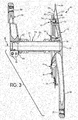
Figure 3 is a transverse cross sectional view of the bicycle crank assembly illustrated inFigures 1 and2 ; -
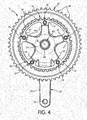
Figure 4 is an inside elevational view of the bicycle crank assembly illustrated inFigures 1 to 3 , but with the left crank arm removed; -
Figure 5 is an exploded perspective view of the bicycle crank assembly illustrated inFigures 1 to 4 ; -
Figure 6 is an enlarged transverse cross sectional view of one of the sprocket attachment portions of the bicycle crank axle assembly illustrated inFigures 1 to 5 ; -
Figure 7 is an enlarged transverse cross sectional view of a sprocket attachment portion of a bicycle crank axle assembly in accordance with a second embodiment; -
Figure 8 is an enlarged transverse cross sectional view of a sprocket attachment portion of a bicycle crank axle assembly in accordance with a third embodiment; -
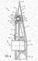
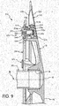
Figure 9 is an enlarged transverse cross sectional view of a sprocket attachment portion of a bicycle crank axle assembly in accordance with a fourth embodiment; -
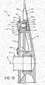
Figure 10 is an enlarged transverse cross sectional view of a sprocket attachment portion of a bicycle crank axle assembly in accordance with a fifth embodiment; and -
Figure 11 is an enlarged transverse cross sectional view of a sprocket attachment portion of a bicycle crank axle assembly in accordance with a sixth embodiment. - Selected embodiments will now be explained with reference to the drawings. It will be apparent to those skilled in the art from this disclosure that the following descriptions of the embodiments are provided for illustration only and not for the purpose of limiting the invention as defined by the appended claims and their equivalents.
- Referring to
Figures 1 to 6 , a bicyclecrank axle assembly 10 is illustrated in accordance with a first embodiment. The bicyclecrank axle assembly 10 includes aright crank arm 12 having afirst sprocket 14 and asecond sprocket 16. The first andsecond sprockets right crank arm 12 in a releasable and reinstallable manner as explained below. The bicyclecrank axle assembly 10 further includes acrank axle 20 and aleft crank arm 22. Theright crank arm 12 is fixed to a first (right) end of thecrank axle 20 in a conventional manner (e.g., crimping, locking ring, adhesive, etc.). Theleft crank arm 22 is fixed to a second (left) end of thecrank axle 20 in a releasable and reinstallable manner (e.g., clamping or other suitable arrangement). - As seen in
Figure 3 , the bicyclecrank axle assembly 10 is rotatably supported by abottom bracket 24 in ahanger tube 26 for rotation about a center rotational axis A of thebottom bracket 24. Thebottom bracket 24 is a conventional structure. Thus, thebottom bracket 24 will not be discussed or illustrated in detail herein. Rather, the following description will primarily focus on the attachment of the first andsecond sprockets right crank arm 12. - First, the first and
second sprockets second sprocket 16 is a solid metal chain ring, while thefirst sprocket 14 is a composite chain ring having an inner shell orcover 30, an outer shell orcover 32 and afiller part 34. The inner andouter shells outer shells outer shells filler part 34 that is preferably made of a plastic resin material or any other suitable filler material. Thefiller part 34 can be considered a resin part when at least partial made of a resin material. Thefiller part 34 can include reinforcing fibers as needed and/or desired. - The
first sprocket 14 includes a plurality offirst teeth 36 and a plurality offirst mounting portions 38 with each having a first mounting opening 40. Thefirst teeth 36 are integrally formed with theinner shell 30 as a one-piece, unitary member. Thefirst mounting portions 38 are mainly formed by theinner shell 30 and portions of thefiller part 34 that surround thefirst mounting openings 40. In the first illustrated embodiment, thefirst sprocket 14 has five of thefirst mounting portions 38 with identical configurations, except that the shape of the exterior side of one of thefirst mounting portions 38 is contoured differently from the remaining four of thefirst mounting portions 38 such that theouter shell 32 flushly mates with theright crank arm 12. The structures of theinner shell 30 forming thefirst mounting portions 38 are identical. However, it will be apparent to those skilled in the art from this disclosure that each of thefirst mounting portions 38 can be substantially different from each other, and that thefirst sprocket 14 can have fewer or more of thefirst mounting portions 38, as needed and/or desired. - Similarly, as best seen in
Figures 5 and6 , thesecond sprocket 16 includes a plurality ofsecond teeth 42 and a plurality of second mountingportions 44 with each of the second mountingportions 44 having a second mountingopening 46. Thesecond sprocket 16 has a recessed portion 48 (Figure 6 ) around the second mountingopening 46. Thesecond sprocket 16 is a one-piece, unitary member that is preferably formed of a suitable metallic material such as a stainless steel, an aluminum alloy, a magnesium alloy, a titanium alloy, etc. In the first illustrated embodiment, thesecond sprocket 16 has five of the second mountingportions 44 with identical configurations. However, it will be apparent to those skilled in the art from this disclosure that the second mountingportions 44 do not need to be identical, and that thesecond sprocket 16 can have fewer or more of the second mountingportions 44, as needed and/or desired. - Now, as seen in
Figures 3 to 5 , theright crank arm 12 will be discussed in more detail. Theright crank arm 12 includes a gear crankportion 50, a crankaxle attachment portion 52 and a plurality ofsprocket attachment portions 54. Theright crank arm 12 is illustrated as being formed with a two-piece construction from a light metal such as an aluminum alloy, a magnesium alloy, a titanium alloy, or other suitable light metal. In particular, a metallic cover member is fixedly attached (i.e., bonded) to a metallic body member that is a one-piece, unitary part. As a result, the gear crankportion 50 has an interior space to reduce the weight of theright crank arm 12. This interior space can be empty or filled with a resin material as needed and/or desired. However, theright crank arm 12 is not limited to this construction. Theright crank arm 12 can be formed of a single piece or of several pieces of various materials. - As seen in
Figures 3 and5 , the gear crankportion 50 has tip or free end portion with apedal attachment hole 56 that is threaded for threadedly attaching a pedal (not shown). The crankaxle attachment portion 52 has a crankaxle attachment hole 58 that has a plurality of splines for engaging thecrank axle 20 to prevent rotation therebetween as seen inFigure 3 . Alternatively, theright crank arm 12 may be designed to be removably fastened to thecrank axle 20 as needed and/or desired. In the first illustrated embodiment, each of thesprocket attachment portions 54 has a third mountingopening 60 as best seen inFigure 5 . The crankaxle attachment portion 52 and thesprocket attachment portions 54 form a substantially starfish-shaped member that functions as a spider arm for the gear crankportion 50. - In order to secure the first and
second sprockets right crank arm 12, the bicycle crankassembly 10 further includes a plurality ofsprocket fixing structures 70. Thesprocket fixing structure 70 secures the first andsecond sprockets crank arm 12 via the first, second and third mountingopenings sprocket fixing structures 70 includes a fixingnut 72 having aninternal thread 72a and a fixingbolt 74 having an external thread 74a. The external thread 74a of the fixingbolt 74 is threaded into theinternal thread 72a of the fixingnut 72 to secure the first andsecond sprockets right crank arm 12. The fixingnut 72 includes anabutment part 72b that contacts one of the first andsecond sprockets bolt 74 includes anabutment part 74b that contacts the other of the first andsecond sprockets abutment part 74b of the fixingbolt 74 is preferably disposed in the recessedportion 48 of thesecond sprocket 16 in the assembled state. - In the first illustrated embodiment, each of the fixing
nuts 72 are embedded in the filler (resin)part 34 of thefirst sprocket 14 so that the fixingnuts 72 align with the first mountingopenings 40. The fixingnuts 72 are preferably formed of a suitable metallic material such as a chrome molybdenum steel, an aluminum alloy, a magnesium alloy, a titanium alloy, etc. In order to accurately position the first andsecond sprockets right crank arm 12, the bicycle crankassembly 10 further includes a plurality ofalignment tubes 76. In the first illustrated embodiment, thealignment tubes 76 are integrally formed with the fixingnuts 72 and extend axially from theabutment part 72b. Thus, thealignment tubes 76 extend through corresponding ones of the first, second and third mountingopenings right crank arm 12 and the first andsecond sprockets alignment tubes 76. Because thealignment tubes 76 are integrally formed with the fixingnuts 72, which are non-detachably, i.e. firmly, fixed to thefirst sprocket 14, it is possible to achieve accurate positioning of the first andsecond sprockets right crank arm 12 even if the center axes of the fixingbolts 74 become inclined with respect to the center axes of the fixingnuts 72 during attachment of the first andsecond sprockets right crank arm 12. Thealignment tubes 76 are cylindrical with an outer diameter that is dimensioned to substantially match the inner diameters of the mountingopenings alignment tubes 76 are not limited to a cylindrical tube. Thealignment tubes 76 can have other shapes that snugly engage the mountingopenings alignment tubes 76 are dimensioned relative to the mountingopenings second sprockets right crank arm 12 and the center rotational axis A. - While in the first illustrated embodiment, each of the
sprocket fixing structures 70 are identical with thealignment tubes 76 integrally formed with the fixingnuts 72, it will be apparent to those skilled in the art from this disclosure that each of thesprocket fixing structures 70 can have a different construction, if needed and/or desired. For example, only one of thesprocket fixing structures 70 can be configured with thealignment tube 76 integrally formed with the fixingnut 72 as seen inFigure 6 , while the remainingsprocket fixing structures 70 can be configured with conventional sprocket fixing structures. Alternatively, for example, some of thesprocket fixing structures 70 can have the configuration as seen inFigure 6 , while other sprocket fixing structures can be either conventional or constructed according to one of the later embodiments. - In the first illustrated embodiment, the
crank axle 20 is a hollow pipe-shaped member that is highly rigid. For example, thecrank axle 20 is made of a metallic material as chrome molybdenum steel. Preferably, thecrank axle 20 defines a longitudinal axis that substantially coincides with the rotational center axis A of thebottom bracket 24. As shown inFigure 3 , the crankarms crank axle 20 and extend in opposite directions. Theleft crank arm 22 is removably fastened to a first or left end portion of thecrank axle 20, while theright crank arm 12 is preferably fixed to a second or right end portion of thecrank axle 20 so that theright crank arm 12 is integrally coupled to thecrank axle 20 through a splined-connection. In particular, as shown inFigure 3 , a first or left end portion of thecrank axle 20 includes a female or internal thread 20a and a plurality of external splines or serrations 20b. - As seen in
Figures 1 to 3 , the left crankarm 22 has a tip or free end portion with apedal attachment hole 80 that is threaded for threadedly attaching a pedal (not shown). As seen inFigure 3 , the left crankarm 22 has a connectinghole 82 with aradial slit 84. The connectinghole 82 of theleft crank arm 22 is mounted on thecrank axle 20. Theleft crank arm 22 is strongly fixed on thecrank axle 20 by tightening up two mountingbolts 86 that are located on the bottom of thecrank axle 20 as seen inFigure 3 . Thus, the width of theslit 84 is narrowed by tightening the mountingbolts 86 that extend across theslit 84 to strongly fix the left crankarm 22 on thecrank axle 20. These two mountingbolts 86 are, for example, hexagon socket head bolts, and their heads are preferably inserted from different directions with respect to theslit 84. - Referring now to
Figure 7 , a sprocket attachment portion of a bicycle crankaxle assembly 110 will now be explained in accordance with a second embodiment. In view of the similarity between the first and second embodiments, the parts of the second embodiment that are identical to the parts of the first embodiment will be given the same reference numerals as the parts of the first embodiment. Moreover, the descriptions of the parts of the second embodiment that are identical to the parts of the first embodiment may be omitted for the sake of brevity. - Here, the
crank axle assembly 110 is provided with a plurality of sprocket fixing structures 170 (only one shown) for securing the first andsecond sprockets right crank arm 12. Each of the fixingstructures 170 includes a fixingnut 172 and a fixingbolt 174. However, aseparate alignment tube 176 is provided for receiving each of thesprocket fixing structures 170. Thus, basically, the only difference between the first and second embodiments is that thealignment tubes 176 are not integrally formed with the fixingnut 172 in thecrank axle assembly 110 of the second embodiment. In other words, each of thealignment tubes 176 is a bushing that extends through the first, second and third mountingopenings - Similar to the first embodiment, the fixing
nut 172 is embedded in the filler (resin)part 34 of thefirst sprocket 14. Also similar to the first embodiment, the fixingbolt 174 has anexternal thread 174a that threadedly engages aninternal thread 172a of the fixingnut 172 to secure the first andsecond sprockets right crank arm 12. The fixingnut 172 also includes anabutment part 172b that contacts thefirst sprocket 14, while the fixingbolt 174 includes anabutment part 174b that contacts thesecond sprocket 16. Theabutment part 174b of the fixingbolt 174 is preferably disposed in the recessedportion 48 of thesecond sprocket 16 in the assembled state. - In the second embodiment, preferably, each of the alignment tubes or bushings 176 (only one shown) includes a tubular portion 176a and a
flange portion 176b. The tubular portion 176a extends through the first, second and third mountingopenings flange portion 176b extends in a radial direction from the tubular portion 176a. Theflange portion 176b is pinched between thesecond sprocket 14 and theabutment part 174b of the fixingbolt 174. In the second embodiment, thealignment tubes 176 are bushings that are separate members from the fixingnuts 172 and the fixingbolt 174. Therefore, even if the center axes of the fixingbolts 174 become inclined with respect to the center axes of the fixingnuts 172 during attachment of the first andsecond sprockets right crank arm 12, such inclination of the fixingbolts 174 less affects positioning of the first andsecond sprockets right crank arm 12. - Referring now to
Figure 8 , a sprocket attachment portion of a bicycle crankaxle assembly 210 will now be explained in accordance a third embodiment. In view of the similarity between the first and third embodiments, the parts of the third embodiment that are identical to the parts of the first embodiment will be given the same reference numerals as the parts of the first embodiment. Moreover, the descriptions of the parts of the third embodiment that are identical to the parts of the first embodiment may be omitted for the sake of brevity. - Here in this third embodiment, the
crank axle assembly 210 is provided with a modifiedfirst sprocket 214 and a plurality of sprocket fixing structures 270 (only one shown) for securing the first andsecond sprockets right crank arm 12. Each of the fixingstructures 270 includes a fixingnut 272 and a fixingbolt 274. However, in this third embodiment, analignment tube 276 is integrally formed with thefirst sprocket 214 at each of the first mountingopenings 240 for receiving each of thesprocket fixing structures 270. Thefirst sprocket 214 is identical to thefirst sprocket 14, discussed above, except that the alignment tubes 276 (only one shown) have been integrally formed with aninner shell 230 of thefirst sprocket 214 at each of the first mountingopenings 240 as a one-piece, unitary member, and that the wall thickness of theinner shell 230 of thefirst sprocket 214 has been increased at each of the first mountingopenings 240. In other words, each of thealignment tubes 276 only extends through the second and third mountingopenings - Similar to the first embodiment, the fixing
nut 272 is embedded in a filler (resin)part 234 of thefirst sprocket 214. Also similar to the first embodiment, the fixingbolt 274 has anexternal thread 274a that threadedly engages aninternal thread 272a of the fixingnut 272 to secure the first andsecond sprockets right crank arm 12. The fixingnut 272 also includes anabutment part 272b that contacts thefirst sprocket 214, while the fixingbolt 274 includes anabutment part 274b that contacts thesecond sprocket 16. Theabutment part 274b of the fixingbolt 274 is preferably disposed in the recessedportion 48 of thesecond sprocket 16 in the assembled state. Because thealignment tubes 276 are integrally formed with thefirst sprocket 214, it is possible to achieve accurate positioning of the first andsecond sprockets right crank arm 12 even if the center axes of the fixingbolts 274 become inclined with respect to the center axes of the fixingnuts 272 during attachment of the first andsecond sprockets right crank arm 12. - Referring now to
Figure 9 , a sprocket attachment portion of a bicycle crankaxle assembly 310 will now be explained in accordance with a fourth embodiment. In view of the similarity between the first and fourth embodiments, the parts of the fourth embodiment that are identical to the parts of the first embodiment will be given the same reference numerals as the parts of the first embodiment. Moreover, the descriptions of the parts of the fourth embodiment that are identical to the parts of the first embodiment may be omitted for the sake of brevity. - Here in this fourth embodiment, the
crank axle assembly 310 is provided with a modifiedfirst sprocket 314, a modified second sprocket 316 and a plurality of sprocket fixing structures 370 (only one shown) for securing the first andsecond sprockets 314 and 316 to theright crank arm 12. Each of the fixingstructures 370 includes a fixingnut 372 and a fixingbolt 374. However, in this fourth embodiment, analignment tube 376 is integrally formed with the second sprocket 316 at each of the second mountingopenings 346 for receiving each of thesprocket fixing structures 370. Thefirst sprocket 314 is identical to thefirst sprocket 14, discussed above, except that the wall thickness of aninner shell 330 of thefirst sprocket 314 has been increased at each of the first mountingopenings 340. The second sprocket 316 is identical to thesecond sprocket 16, discussed above, except that thealignment tubes 376 have been integrally formed with the second sprocket 316 as a one-piece, unitary member. In other words, each of thealignment tubes 376 only extends through the first and third mountingopenings - Similar to the first embodiment, the fixing
nut 372 is embedded in a filler (resin)part 334 of thefirst sprocket 314. Also similar to the first embodiment, the fixingbolt 374 has anexternal thread 374a that threadedly engages aninternal thread 372a of the fixingnut 372 to secure the first andsecond sprockets 314 and 316 to theright crank arm 12. The fixingnut 372 also includes anabutment part 372b that contacts thefirst sprocket 314, while the fixingbolt 374 includes anabutment part 374b that contacts the second sprocket 316. Theabutment part 374b of the fixingbolt 374 is preferably disposed in a recessedportion 348 of thesprocket mounting portion 344 of the second sprocket 316 in the assembled state. Because thealignment tubes 376 are integrally formed with the second sprocket 316, it is possible to achieve accurate positioning of the first andsecond sprockets 314 and 316 and theright crank arm 12 even if the center axes of the fixingbolts 374 become inclined with respect to the center axes of the fixingnuts 372 during attachment of the first andsecond sprockets 314 and 316 to theright crank arm 12. - Referring now to
Figure 10 , a sprocket attachment portion of a bicycle crankaxle assembly 410 will now be explained in accordance a fifth embodiment. In view of the similarity between the first and fifth embodiments, the parts of the fifth embodiment that are identical to the parts of the first embodiment will be given the same reference numerals as the parts of the first embodiment. Moreover, the descriptions of the parts of the fifth embodiment that are identical to the parts of the first embodiment may be omitted for the sake of brevity. - Here in this fifth embodiment, the
crank axle assembly 410 is provided with a modified right crankarm 412, a modifiedfirst sprocket 414, and a plurality of sprocket fixing structures 470 (only one shown) for securing the first andsecond sprockets right crank arm 412. Each of the fixingstructures 470 includes a fixingnut 472 and a fixingbolt 474. However, in this fifth embodiment, analignment tube 476 is integrally formed with thecrank arm 412 on eachsprocket attachment portion 454 at each of the third mountingopenings 460 for receiving each of thesprocket fixing structures 470. Thefirst sprocket 414 is identical to thefirst sprocket 14, discussed above, except that the wall thickness of aninner shell 430 of thefirst sprocket 414 has been increased at each of the first mountingopenings 440. Theright crank arm 412 is identical to theright crank arm 12, discussed above, except that the alignment tubes 476 (only one shown) are integrally formed with thecrank arm 412 at each of the third mountingopenings 460. Thealignment tubes 476 extend in opposite axial directions with respect to the center axes of the third mountingopenings 460 from the sprocket attachment portions 454 (only one shown). In other words, each of thealignment tubes 476 only extends through the first and second mountingopenings - Similar to the first embodiment, the fixing
nut 472 is embedded in a filler (resin)part 434 of thefirst sprocket 414. Also similar to the first embodiment, the fixingbolt 474 has anexternal thread 474a that threadedly engages aninternal thread 472a of the fixingnut 472 to secure the first andsecond sprockets right crank arm 412. The fixingnut 472 also includes anabutment part 472b that contacts thefirst sprocket 414, while the fixingbolt 474 includes anabutment part 474b that contacts thesecond sprocket 16. Theabutment part 474b of the fixingbolt 474 is preferably disposed in the recessedportion 48 of thesecond sprocket 16 in the assembled state. Because thealignment tubes 476 are integrally formed with thecrank arm 412, it is possible to achieve accurate positioning of the first andsecond sprockets crank arm 412 even if the center axes of the fixingbolts 474 become inclined with respect to the center axes of the fixingnuts 472 during attachment of the first andsecond sprockets right crank arm 412. - Referring now to
Figure 11 , a sprocket attachment portion of a bicycle crankaxle assembly 510 will now be explained in accordance with a sixth embodiment. In view of the similarity between the first and sixth embodiments, the parts of the sixth embodiment that are identical to the parts of the first embodiment will be given the same reference numerals as the parts of the first embodiment. Moreover, the descriptions of the parts of the sixth embodiment that are identical to the parts of the first embodiment may be omitted for the sake of brevity. - Here in this sixth embodiment, the
crank axle assembly 510 is provided with a modified right crankarm 512, a modifiedfirst sprocket 514, and a plurality of sprocket fixing structures 570 (only one shown) for securing the first andsecond sprockets right crank arm 512. In this sixth embodiment, each of the fixingstructures 570 includes afirst fixing bolt 572 with anexternal thread 572a and asecond fixing bolt 574 with anexternal thread 574a. Thus, the fixing nut of the prior embodiments has been replaced with thefirst fixing bolt 572 in this sixth embodiment. Also, in this sixth embodiment, analignment tube 576 is integrally formed with thecrank arm 512 on each sprocket attachment portion 554 at each of the third mountingopenings 560 for receiving each of thesprocket fixing structures 570. Each of the alignment tubes 576 (only one shown) of thecrank arm 512 has aninternal thread 576a formed along the third mountingopenings 560 so that theexternal threads bolts internal thread 576a of thealignment tubes 576 of thecrank arm 512. - The
first sprocket 514 is identical to thefirst sprocket 14, discussed above, except that the wall thickness of aninner shell 530 of thefirst sprocket 514 has been increased at each of the first mountingopenings 540 and anouter shell 532 of thefirst sprocket 514 has been provided with anopening 532a at each of thesprocket fixing structures 570 for accessing the in the first fixingbolts 572. Theright crank arm 512 is identical to theright crank arm 12, discussed above, except that the alignment tubes 576 (only one shown) are integrally formed with thecrank arm 512 at each of the third mountingopenings 560 and the alignment tubes 576 (only one shown) are each provided with theinternal thread 576a. Thealignment tubes 576 extend in opposite axial directions with respect to the center axes of the third mountingopenings 560 from the sprocket attachment portions 554 (only one shown) of thecrank arm 512. In other words, each of thealignment tubes 576 only extends through the first and second mountingopenings - In this sixth embodiment, each of the first fixing
bolts 572 also includes anabutment part 572b that contacts thefirst sprocket 514, while each of the second fixingbolts 574 includes anabutment part 574b that contacts thesecond sprocket 16. Theabutment part 574b of the fixingbolt 574 is preferably disposed in the recessedportion 48 of thesecond sprocket 16 in the assembled state. Because thealignment tubes 576 are integrally formed with thecrank arm 512, it is possible to achieve accurate positioning of the first andsecond sprockets crank arm 512 even if the center axes of the first and second fixingbolts internal threads 576a during attachment of the first andsecond sprockets crank arm 512. - In understanding the scope of the present invention, the term "comprising" and its derivatives, as used herein, are intended to be open ended terms that specify the presence of the stated features, elements, components, groups, integers, and/or steps, but do not exclude the presence of other unstated features, elements, components, groups, integers and/or steps. The foregoing also applies to words having similar meanings such as the terms, "including", "having" and their derivatives. Also, the terms "part," "section," "portion," "member" or "element" when used in the singular can have the dual meaning of a single part or a plurality of parts. As used herein to describe the above embodiment(s), the following directional terms "forward", "rearward", "above", "downward", "vertical", "horizontal", "below" and "transverse" as well as any other similar directional terms refer to those directions of a bicycle equipped with the bicycle crank assembly. Accordingly, these terms, as utilized to describe the bicycle crank assembly should be interpreted relative to a bicycle equipped with the bicycle crank assembly as used in the normal riding position on a flat horizontal surface. Finally, terms of degree such as "substantially", "about" and "approximately" as used herein mean a reasonable amount of deviation of the modified term such that the end result is not significantly changed.
- While only selected embodiments have been chosen to illustrate the present invention, it will be apparent to those skilled in the art from this disclosure that various changes and modifications can be made herein without departing from the scope of the invention as defined in the appended claims. For example, the size, shape, location or orientation of the various components can be changed as needed and/or desired. Components that are shown directly connected or contacting each other can have intermediate structures disposed between them. The functions of one element can be performed by two, and vice versa. The structures and functions of one embodiment can be adopted in another embodiment. It is not necessary for all advantages to be present in a particular embodiment at the same time. Every feature which is unique from the prior art, alone or in combination with other features, also should be considered a separate description of further inventions by the applicant, including the structural and/or functional concepts embodied by such feature(s). Thus, the foregoing descriptions of the embodiments according to the present invention are provided for illustration only, and not for the purpose of limiting the invention as defined by the appended claims and their equivalents.
Claims (12)
- A bicycle crank assembly comprising:a first sprocket including a plurality of first teeth and at least one first mounting portion having a first mounting opening;a second sprocket including a plurality of second teeth and at least one second mounting portion having a second mounting opening;a crank arm including at least one sprocket attachment portion having a third mounting opening;a sprocket fixing structure securing the first and second sprockets to the crank arm via the first, second and third mounting openings; andan alignment tube extending through at least two of the first, second and third mounting openings.
- The bicycle crank assembly according to claim 1, wherein
the alignment tube is non-detachably fixed to or integrally formed with one of the first sprocket, the second sprocket and the crank arm. - The bicycle crank assembly according to claim 1 or 2, wherein
the alignment tube is integrally formed with the first sprocket and extends through the second and third mounting openings. - The bicycle crank assembly according to claim 1 or 2, wherein
the alignment tube is integrally formed with the second sprocket and extends through the first and third mounting openings. - The bicycle crank assembly according to claim 1 or 2, wherein
the alignment tube is integrally formed with the crank arm and extends through the first and second mounting openings. - The bicycle crank assembly according to claim 1 or 2, wherein
the alignment tube is a bushing that is a separate member from the sprocket fixing structure, and
the bushing extends through the first, second and third mounting openings. - The bicycle crank assembly according to any one of claims 1 to 6, wherein
the sprocket fixing structure includes a fixing nut having an internal thread and a fixing bolt having an external thread, the external thread of the fixing bolt being threaded into the internal thread of the fixing nut, in particular the fixing nut being embedded in a resin part of the first sprocket. - The bicycle crank assembly according to claim 7, wherein
the alignment tube being integrally formed with the fixing nut and extends through the first, second and third mounting openings. - The bicycle crank assembly according to claim 7 or 8 when dependent on claim 6, wherein
the bushing includes a tubular portion that extends through the first, second and third mounting openings and a flange portion that extends in a radial direction from the tubular portion, the flange portion being pinched between one of the first and second sprockets and one of the fixing bolt and the fixing nut. - The bicycle crank assembly according to any one of claims 7 to 9, wherein
the fixing nut includes an abutment part that contacts one of the first and second sprockets and the fixing bolt includes an abutment part that contacts the other of the first and second sprockets. - The bicycle crank assembly according to claim 10, wherein
at least one of the first and second sprockets has a recessed portion around at least one of the first and second mounting openings so that the abutment part of one of the fixing bolt and the fixing nut is disposed in the recessed portion upon assembled state. - The bicycle crank assembly according to any one of claims 1 to 11, wherein
the sprocket fixing structure includes a first fixing bolt having an external thread and a second fixing bolt having an external thread, and
the alignment tube has an internal thread so that the external threads of the first and second fixing bolts are threaded into the internal thread of the alignment tube.
Applications Claiming Priority (1)
| Application Number | Priority Date | Filing Date | Title |
|---|---|---|---|
| US13/253,113 US9771128B2 (en) | 2011-10-05 | 2011-10-05 | Bicycle crank assembly |
Publications (2)
| Publication Number | Publication Date |
|---|---|
| EP2578486A1 true EP2578486A1 (en) | 2013-04-10 |
| EP2578486B1 EP2578486B1 (en) | 2019-09-11 |
Family
ID=46614335
Family Applications (1)
| Application Number | Title | Priority Date | Filing Date |
|---|---|---|---|
| EP12178460.7A Active EP2578486B1 (en) | 2011-10-05 | 2012-07-30 | Bicycle crank assembly |
Country Status (4)
| Country | Link |
|---|---|
| US (1) | US9771128B2 (en) |
| EP (1) | EP2578486B1 (en) |
| CN (1) | CN103029797B (en) |
| TW (1) | TWI495596B (en) |
Cited By (1)
| Publication number | Priority date | Publication date | Assignee | Title |
|---|---|---|---|---|
| EP3401203A1 (en) * | 2017-04-28 | 2018-11-14 | Fox Factory, Inc. | A chainring assembly |
Families Citing this family (13)
| Publication number | Priority date | Publication date | Assignee | Title |
|---|---|---|---|---|
| ITMI20120088U1 (en) * | 2012-03-08 | 2013-09-09 | Campagnolo Srl | ASSEMBLY OF RIGHT PEDESTAL FOR BICYCLE |
| CN104443241B (en) * | 2013-09-18 | 2019-02-05 | 介隆兴齿轮股份有限公司 | Crank structure of chainless transmission bicycle |
| US11041558B2 (en) * | 2014-03-14 | 2021-06-22 | ZPE Licensing Inc. | Super charger components |
| US9919763B2 (en) * | 2014-06-16 | 2018-03-20 | Shimano Inc. | Bicycle sprocket |
| DE202014103464U1 (en) * | 2014-07-28 | 2015-10-29 | Brose Fahrzeugteile Gmbh & Co. Kommanditgesellschaft, Coburg | Drive device for an electric bike |
| US10377445B2 (en) * | 2016-09-20 | 2019-08-13 | Shimano Inc. | Bicycle front sprocket assembly |
| US10794663B2 (en) | 2017-05-11 | 2020-10-06 | ZPE Licensing Inc. | Laser induced friction surface on firearm |
| US11148753B2 (en) * | 2017-12-20 | 2021-10-19 | Sram, Llc | Sprocket assembly |
| US11292555B2 (en) * | 2018-08-01 | 2022-04-05 | Shimano Inc. | Bicycle sprocket |
| US11814135B2 (en) * | 2022-04-14 | 2023-11-14 | Shimano Inc. | Crank assembly for human powered vehicle |
| US20230330475A1 (en) * | 2022-04-18 | 2023-10-19 | Xiamen Evere Sports Goods Co., Ltd. | Crank for fitness equipment with self-locking mechanism |
| US12209619B2 (en) | 2022-04-20 | 2025-01-28 | ZPE Licensing Inc. | Electromagnetic clutch |
| US12384009B2 (en) | 2022-11-15 | 2025-08-12 | ZPE Licensing Inc. | Socket with laser induced friction surfaces |
Citations (6)
| Publication number | Priority date | Publication date | Assignee | Title |
|---|---|---|---|---|
| JPS596186A (en) * | 1982-07-02 | 1984-01-13 | 株式会社シマノ | Chain gear of gear crank device for bicycle |
| EP0417696A1 (en) * | 1989-09-12 | 1991-03-20 | Shimano Inc. | Multi-gear cluster for bicycle |
| EP0513681A1 (en) * | 1991-05-13 | 1992-11-19 | Shimano Inc. | Front gear apparatus for a bicycle having a chain restoring device |
| EP1609714A2 (en) * | 2004-06-22 | 2005-12-28 | Shimano Inc. | Bicycle sprocket |
| US7258041B2 (en) | 2003-02-18 | 2007-08-21 | Shimano Inc. | Bicycle crank assembly |
| TW201024170A (en) * | 2008-12-23 | 2010-07-01 | Sakae Engineering Inc | Bicycle tooth disc |
Family Cites Families (20)
| Publication number | Priority date | Publication date | Assignee | Title |
|---|---|---|---|---|
| NL9300321A (en) * | 1993-02-22 | 1994-09-16 | Yamaha Motor Europ | Mechanism for driving a vehicle comprising a frame. |
| JPH0667289U (en) * | 1993-03-09 | 1994-09-22 | 株式会社シマノ | Bicycle front gear unit and bicycle crank used in this front gear unit |
| US5766106A (en) * | 1995-09-08 | 1998-06-16 | Edwards; Craig H. | Crankset assembly |
| US5791203A (en) * | 1996-07-18 | 1998-08-11 | Chen; Chia-Lung | Bicycle crankset |
| US5904072A (en) * | 1996-12-20 | 1999-05-18 | Shimano Inc. | Bicycle crank arm |
| JP3248675B2 (en) * | 1996-12-27 | 2002-01-21 | 株式会社シマノ | Manufacturing method of bicycle crank |
| DE19717463A1 (en) * | 1997-04-25 | 1998-10-29 | Sram De Gmbh | Crank arm for pedal drive of bicycle |
| AU2002330033A1 (en) * | 2001-09-17 | 2003-04-01 | Compositech, Inc. | High performance bicycle crank |
| US7503239B2 (en) * | 2003-01-30 | 2009-03-17 | Shimano Inc. | Bicycle crank arm assembly |
| JP2006151159A (en) * | 2004-11-29 | 2006-06-15 | Shimano Inc | Fixing structure of crank for bicycle |
| US7240586B2 (en) * | 2005-03-14 | 2007-07-10 | Wu Donald P H | Auxiliary power unit starting apparatus for an electric bicycle |
| US7686721B2 (en) * | 2005-05-11 | 2010-03-30 | Shimano Inc. | Bicycle chainring |
| US7824287B2 (en) * | 2005-12-02 | 2010-11-02 | Shimano Inc. | Bicycle sprocket |
| US20080161145A1 (en) | 2006-12-28 | 2008-07-03 | Shimano Inc. | Bicycle chain wheel with fastener cover |
| US7650818B2 (en) * | 2007-03-30 | 2010-01-26 | Shimano Inc. | Bicycle shaft component |
| ITMI20070669A1 (en) * | 2007-04-02 | 2008-10-03 | Campagnolo Srl | INSTRUMENTED BICYCLE COMPONENT AND DETECTION UNIT TO INSTRUMENT THIS COMPONENT |
| US20080245180A1 (en) * | 2007-04-09 | 2008-10-09 | Yuan-Hsin Huang | Assembly structure of treading crank and spindle tube of the bike |
| US7975561B1 (en) * | 2008-02-29 | 2011-07-12 | Saris Cycling Group, Inc. | Chain ring power sensor for a bicycle |
| JP2010058589A (en) * | 2008-09-02 | 2010-03-18 | Sugino Engineering:Kk | Bicycle gear crank |
| US8616085B2 (en) * | 2010-08-18 | 2013-12-31 | Shimano Inc. | Bicycle crank assembly |
-
2011
- 2011-10-05 US US13/253,113 patent/US9771128B2/en active Active
-
2012
- 2012-04-26 TW TW101115008A patent/TWI495596B/en active
- 2012-06-11 CN CN201210190007.5A patent/CN103029797B/en active Active
- 2012-07-30 EP EP12178460.7A patent/EP2578486B1/en active Active
Patent Citations (6)
| Publication number | Priority date | Publication date | Assignee | Title |
|---|---|---|---|---|
| JPS596186A (en) * | 1982-07-02 | 1984-01-13 | 株式会社シマノ | Chain gear of gear crank device for bicycle |
| EP0417696A1 (en) * | 1989-09-12 | 1991-03-20 | Shimano Inc. | Multi-gear cluster for bicycle |
| EP0513681A1 (en) * | 1991-05-13 | 1992-11-19 | Shimano Inc. | Front gear apparatus for a bicycle having a chain restoring device |
| US7258041B2 (en) | 2003-02-18 | 2007-08-21 | Shimano Inc. | Bicycle crank assembly |
| EP1609714A2 (en) * | 2004-06-22 | 2005-12-28 | Shimano Inc. | Bicycle sprocket |
| TW201024170A (en) * | 2008-12-23 | 2010-07-01 | Sakae Engineering Inc | Bicycle tooth disc |
Cited By (1)
| Publication number | Priority date | Publication date | Assignee | Title |
|---|---|---|---|---|
| EP3401203A1 (en) * | 2017-04-28 | 2018-11-14 | Fox Factory, Inc. | A chainring assembly |
Also Published As
| Publication number | Publication date |
|---|---|
| US9771128B2 (en) | 2017-09-26 |
| US20130087012A1 (en) | 2013-04-11 |
| TW201315648A (en) | 2013-04-16 |
| TWI495596B (en) | 2015-08-11 |
| CN103029797A (en) | 2013-04-10 |
| EP2578486B1 (en) | 2019-09-11 |
| CN103029797B (en) | 2015-12-02 |
Similar Documents
| Publication | Publication Date | Title |
|---|---|---|
| EP2578486B1 (en) | Bicycle crank assembly | |
| US11713801B2 (en) | Bicycle sprocket | |
| EP1845015B1 (en) | Bicycle crank | |
| US11097807B2 (en) | Bicycle hub assembly | |
| US8677859B2 (en) | Bicycle crank axle assembly | |
| CN102372065B (en) | Bicycle crank assembly | |
| US10968998B2 (en) | Bicycle rear sprocket adapter | |
| US8438947B2 (en) | Bicycle crank arm | |
| CN107792286B (en) | Bicycle crank arm | |
| US7464994B2 (en) | Bicycle rim reinforced with a continuously extending resin material | |
| EP1958760A2 (en) | Composite bicycle frame with bottom bracket assembly, fork and seat attachment | |
| EP1726457B1 (en) | Bicycle hub | |
| EP2487047A1 (en) | Bicycle rim | |
| EP0764575B1 (en) | Bicycle crank set | |
| US10315724B2 (en) | Composite bicycle component | |
| US20050282672A1 (en) | Bicycle sprocket | |
| US7331639B2 (en) | Bicycle rim | |
| US10442496B2 (en) | Bicycle sprocket assembly | |
| CN112722145B (en) | Bicycle hub assembly | |
| US7374251B2 (en) | Connection of Spokes to hub and rim in bicycle wheel |
Legal Events
| Date | Code | Title | Description |
|---|---|---|---|
| PUAI | Public reference made under article 153(3) epc to a published international application that has entered the european phase |
Free format text: ORIGINAL CODE: 0009012 |
|
| AK | Designated contracting states |
Kind code of ref document: A1 Designated state(s): AL AT BE BG CH CY CZ DE DK EE ES FI FR GB GR HR HU IE IS IT LI LT LU LV MC MK MT NL NO PL PT RO RS SE SI SK SM TR |
|
| AX | Request for extension of the european patent |
Extension state: BA ME |
|
| 17P | Request for examination filed |
Effective date: 20131010 |
|
| RBV | Designated contracting states (corrected) |
Designated state(s): AL AT BE BG CH CY CZ DE DK EE ES FI FR GB GR HR HU IE IS IT LI LT LU LV MC MK MT NL NO PL PT RO RS SE SI SK SM TR |
|
| 17Q | First examination report despatched |
Effective date: 20140703 |
|
| STAA | Information on the status of an ep patent application or granted ep patent |
Free format text: STATUS: EXAMINATION IS IN PROGRESS |
|
| GRAP | Despatch of communication of intention to grant a patent |
Free format text: ORIGINAL CODE: EPIDOSNIGR1 |
|
| STAA | Information on the status of an ep patent application or granted ep patent |
Free format text: STATUS: GRANT OF PATENT IS INTENDED |
|
| INTG | Intention to grant announced |
Effective date: 20190225 |
|
| GRAS | Grant fee paid |
Free format text: ORIGINAL CODE: EPIDOSNIGR3 |
|
| GRAA | (expected) grant |
Free format text: ORIGINAL CODE: 0009210 |
|
| STAA | Information on the status of an ep patent application or granted ep patent |
Free format text: STATUS: THE PATENT HAS BEEN GRANTED |
|
| AK | Designated contracting states |
Kind code of ref document: B1 Designated state(s): AL AT BE BG CH CY CZ DE DK EE ES FI FR GB GR HR HU IE IS IT LI LT LU LV MC MK MT NL NO PL PT RO RS SE SI SK SM TR |
|
| REG | Reference to a national code |
Ref country code: GB Ref legal event code: FG4D |
|
| REG | Reference to a national code |
Ref country code: CH Ref legal event code: EP |
|
| REG | Reference to a national code |
Ref country code: AT Ref legal event code: REF Ref document number: 1178111 Country of ref document: AT Kind code of ref document: T Effective date: 20190915 |
|
| REG | Reference to a national code |
Ref country code: DE Ref legal event code: R096 Ref document number: 602012063827 Country of ref document: DE Ref country code: IE Ref legal event code: FG4D |
|
| REG | Reference to a national code |
Ref country code: NL Ref legal event code: MP Effective date: 20190911 |
|
| REG | Reference to a national code |
Ref country code: LT Ref legal event code: MG4D |
|
| PG25 | Lapsed in a contracting state [announced via postgrant information from national office to epo] |
Ref country code: FI Free format text: LAPSE BECAUSE OF FAILURE TO SUBMIT A TRANSLATION OF THE DESCRIPTION OR TO PAY THE FEE WITHIN THE PRESCRIBED TIME-LIMIT Effective date: 20190911 Ref country code: NO Free format text: LAPSE BECAUSE OF FAILURE TO SUBMIT A TRANSLATION OF THE DESCRIPTION OR TO PAY THE FEE WITHIN THE PRESCRIBED TIME-LIMIT Effective date: 20191211 Ref country code: BG Free format text: LAPSE BECAUSE OF FAILURE TO SUBMIT A TRANSLATION OF THE DESCRIPTION OR TO PAY THE FEE WITHIN THE PRESCRIBED TIME-LIMIT Effective date: 20191211 Ref country code: SE Free format text: LAPSE BECAUSE OF FAILURE TO SUBMIT A TRANSLATION OF THE DESCRIPTION OR TO PAY THE FEE WITHIN THE PRESCRIBED TIME-LIMIT Effective date: 20190911 Ref country code: HR Free format text: LAPSE BECAUSE OF FAILURE TO SUBMIT A TRANSLATION OF THE DESCRIPTION OR TO PAY THE FEE WITHIN THE PRESCRIBED TIME-LIMIT Effective date: 20190911 Ref country code: LT Free format text: LAPSE BECAUSE OF FAILURE TO SUBMIT A TRANSLATION OF THE DESCRIPTION OR TO PAY THE FEE WITHIN THE PRESCRIBED TIME-LIMIT Effective date: 20190911 |
|
| PG25 | Lapsed in a contracting state [announced via postgrant information from national office to epo] |
Ref country code: RS Free format text: LAPSE BECAUSE OF FAILURE TO SUBMIT A TRANSLATION OF THE DESCRIPTION OR TO PAY THE FEE WITHIN THE PRESCRIBED TIME-LIMIT Effective date: 20190911 Ref country code: LV Free format text: LAPSE BECAUSE OF FAILURE TO SUBMIT A TRANSLATION OF THE DESCRIPTION OR TO PAY THE FEE WITHIN THE PRESCRIBED TIME-LIMIT Effective date: 20190911 Ref country code: AL Free format text: LAPSE BECAUSE OF FAILURE TO SUBMIT A TRANSLATION OF THE DESCRIPTION OR TO PAY THE FEE WITHIN THE PRESCRIBED TIME-LIMIT Effective date: 20190911 Ref country code: ES Free format text: LAPSE BECAUSE OF FAILURE TO SUBMIT A TRANSLATION OF THE DESCRIPTION OR TO PAY THE FEE WITHIN THE PRESCRIBED TIME-LIMIT Effective date: 20190911 Ref country code: GR Free format text: LAPSE BECAUSE OF FAILURE TO SUBMIT A TRANSLATION OF THE DESCRIPTION OR TO PAY THE FEE WITHIN THE PRESCRIBED TIME-LIMIT Effective date: 20191212 |
|
| REG | Reference to a national code |
Ref country code: AT Ref legal event code: MK05 Ref document number: 1178111 Country of ref document: AT Kind code of ref document: T Effective date: 20190911 |
|
| PG25 | Lapsed in a contracting state [announced via postgrant information from national office to epo] |
Ref country code: EE Free format text: LAPSE BECAUSE OF FAILURE TO SUBMIT A TRANSLATION OF THE DESCRIPTION OR TO PAY THE FEE WITHIN THE PRESCRIBED TIME-LIMIT Effective date: 20190911 Ref country code: PL Free format text: LAPSE BECAUSE OF FAILURE TO SUBMIT A TRANSLATION OF THE DESCRIPTION OR TO PAY THE FEE WITHIN THE PRESCRIBED TIME-LIMIT Effective date: 20190911 Ref country code: PT Free format text: LAPSE BECAUSE OF FAILURE TO SUBMIT A TRANSLATION OF THE DESCRIPTION OR TO PAY THE FEE WITHIN THE PRESCRIBED TIME-LIMIT Effective date: 20200113 Ref country code: RO Free format text: LAPSE BECAUSE OF FAILURE TO SUBMIT A TRANSLATION OF THE DESCRIPTION OR TO PAY THE FEE WITHIN THE PRESCRIBED TIME-LIMIT Effective date: 20190911 Ref country code: IT Free format text: LAPSE BECAUSE OF FAILURE TO SUBMIT A TRANSLATION OF THE DESCRIPTION OR TO PAY THE FEE WITHIN THE PRESCRIBED TIME-LIMIT Effective date: 20190911 Ref country code: AT Free format text: LAPSE BECAUSE OF FAILURE TO SUBMIT A TRANSLATION OF THE DESCRIPTION OR TO PAY THE FEE WITHIN THE PRESCRIBED TIME-LIMIT Effective date: 20190911 Ref country code: NL Free format text: LAPSE BECAUSE OF FAILURE TO SUBMIT A TRANSLATION OF THE DESCRIPTION OR TO PAY THE FEE WITHIN THE PRESCRIBED TIME-LIMIT Effective date: 20190911 |
|
| PG25 | Lapsed in a contracting state [announced via postgrant information from national office to epo] |
Ref country code: SK Free format text: LAPSE BECAUSE OF FAILURE TO SUBMIT A TRANSLATION OF THE DESCRIPTION OR TO PAY THE FEE WITHIN THE PRESCRIBED TIME-LIMIT Effective date: 20190911 Ref country code: SM Free format text: LAPSE BECAUSE OF FAILURE TO SUBMIT A TRANSLATION OF THE DESCRIPTION OR TO PAY THE FEE WITHIN THE PRESCRIBED TIME-LIMIT Effective date: 20190911 Ref country code: CZ Free format text: LAPSE BECAUSE OF FAILURE TO SUBMIT A TRANSLATION OF THE DESCRIPTION OR TO PAY THE FEE WITHIN THE PRESCRIBED TIME-LIMIT Effective date: 20190911 Ref country code: IS Free format text: LAPSE BECAUSE OF FAILURE TO SUBMIT A TRANSLATION OF THE DESCRIPTION OR TO PAY THE FEE WITHIN THE PRESCRIBED TIME-LIMIT Effective date: 20200224 |
|
| REG | Reference to a national code |
Ref country code: DE Ref legal event code: R097 Ref document number: 602012063827 Country of ref document: DE |
|
| PLBE | No opposition filed within time limit |
Free format text: ORIGINAL CODE: 0009261 |
|
| STAA | Information on the status of an ep patent application or granted ep patent |
Free format text: STATUS: NO OPPOSITION FILED WITHIN TIME LIMIT |
|
| PG2D | Information on lapse in contracting state deleted |
Ref country code: IS |
|
| PG25 | Lapsed in a contracting state [announced via postgrant information from national office to epo] |
Ref country code: DK Free format text: LAPSE BECAUSE OF FAILURE TO SUBMIT A TRANSLATION OF THE DESCRIPTION OR TO PAY THE FEE WITHIN THE PRESCRIBED TIME-LIMIT Effective date: 20190911 Ref country code: IS Free format text: LAPSE BECAUSE OF FAILURE TO SUBMIT A TRANSLATION OF THE DESCRIPTION OR TO PAY THE FEE WITHIN THE PRESCRIBED TIME-LIMIT Effective date: 20200112 |
|
| 26N | No opposition filed |
Effective date: 20200615 |
|
| PG25 | Lapsed in a contracting state [announced via postgrant information from national office to epo] |
Ref country code: SI Free format text: LAPSE BECAUSE OF FAILURE TO SUBMIT A TRANSLATION OF THE DESCRIPTION OR TO PAY THE FEE WITHIN THE PRESCRIBED TIME-LIMIT Effective date: 20190911 |
|
| REG | Reference to a national code |
Ref country code: DE Ref legal event code: R082 Ref document number: 602012063827 Country of ref document: DE Representative=s name: SONNENBERG HARRISON PARTNERSCHAFT MBB, DE Ref country code: DE Ref legal event code: R082 Ref document number: 602012063827 Country of ref document: DE Representative=s name: SONNENBERG HARRISON PARTNERSCHAFT MBB PATENT- , DE |
|
| PG25 | Lapsed in a contracting state [announced via postgrant information from national office to epo] |
Ref country code: MC Free format text: LAPSE BECAUSE OF FAILURE TO SUBMIT A TRANSLATION OF THE DESCRIPTION OR TO PAY THE FEE WITHIN THE PRESCRIBED TIME-LIMIT Effective date: 20190911 |
|
| REG | Reference to a national code |
Ref country code: CH Ref legal event code: PL |
|
| GBPC | Gb: european patent ceased through non-payment of renewal fee |
Effective date: 20200730 |
|
| REG | Reference to a national code |
Ref country code: BE Ref legal event code: MM Effective date: 20200731 |
|
| PG25 | Lapsed in a contracting state [announced via postgrant information from national office to epo] |
Ref country code: GB Free format text: LAPSE BECAUSE OF NON-PAYMENT OF DUE FEES Effective date: 20200730 Ref country code: FR Free format text: LAPSE BECAUSE OF NON-PAYMENT OF DUE FEES Effective date: 20200731 Ref country code: LU Free format text: LAPSE BECAUSE OF NON-PAYMENT OF DUE FEES Effective date: 20200730 Ref country code: CH Free format text: LAPSE BECAUSE OF NON-PAYMENT OF DUE FEES Effective date: 20200731 Ref country code: LI Free format text: LAPSE BECAUSE OF NON-PAYMENT OF DUE FEES Effective date: 20200731 |
|
| PG25 | Lapsed in a contracting state [announced via postgrant information from national office to epo] |
Ref country code: BE Free format text: LAPSE BECAUSE OF NON-PAYMENT OF DUE FEES Effective date: 20200731 |
|
| PG25 | Lapsed in a contracting state [announced via postgrant information from national office to epo] |
Ref country code: IE Free format text: LAPSE BECAUSE OF NON-PAYMENT OF DUE FEES Effective date: 20200730 |
|
| PG25 | Lapsed in a contracting state [announced via postgrant information from national office to epo] |
Ref country code: TR Free format text: LAPSE BECAUSE OF FAILURE TO SUBMIT A TRANSLATION OF THE DESCRIPTION OR TO PAY THE FEE WITHIN THE PRESCRIBED TIME-LIMIT Effective date: 20190911 Ref country code: MT Free format text: LAPSE BECAUSE OF FAILURE TO SUBMIT A TRANSLATION OF THE DESCRIPTION OR TO PAY THE FEE WITHIN THE PRESCRIBED TIME-LIMIT Effective date: 20190911 Ref country code: CY Free format text: LAPSE BECAUSE OF FAILURE TO SUBMIT A TRANSLATION OF THE DESCRIPTION OR TO PAY THE FEE WITHIN THE PRESCRIBED TIME-LIMIT Effective date: 20190911 |
|
| PG25 | Lapsed in a contracting state [announced via postgrant information from national office to epo] |
Ref country code: MK Free format text: LAPSE BECAUSE OF FAILURE TO SUBMIT A TRANSLATION OF THE DESCRIPTION OR TO PAY THE FEE WITHIN THE PRESCRIBED TIME-LIMIT Effective date: 20190911 |
|
| P01 | Opt-out of the competence of the unified patent court (upc) registered |
Effective date: 20230424 |
|
| PGFP | Annual fee paid to national office [announced via postgrant information from national office to epo] |
Ref country code: DE Payment date: 20250722 Year of fee payment: 14 |