EP0417696A1 - Multi-gear cluster for bicycle - Google Patents
Multi-gear cluster for bicycle Download PDFInfo
- Publication number
- EP0417696A1 EP0417696A1 EP90117397A EP90117397A EP0417696A1 EP 0417696 A1 EP0417696 A1 EP 0417696A1 EP 90117397 A EP90117397 A EP 90117397A EP 90117397 A EP90117397 A EP 90117397A EP 0417696 A1 EP0417696 A1 EP 0417696A1
- Authority
- EP
- European Patent Office
- Prior art keywords
- gear
- tooth
- disengagement
- chain
- teeth
- Prior art date
- Legal status (The legal status is an assumption and is not a legal conclusion. Google has not performed a legal analysis and makes no representation as to the accuracy of the status listed.)
- Granted
Links
Images


Classifications
-
- B—PERFORMING OPERATIONS; TRANSPORTING
- B62—LAND VEHICLES FOR TRAVELLING OTHERWISE THAN ON RAILS
- B62M—RIDER PROPULSION OF WHEELED VEHICLES OR SLEDGES; POWERED PROPULSION OF SLEDGES OR SINGLE-TRACK CYCLES; TRANSMISSIONS SPECIALLY ADAPTED FOR SUCH VEHICLES
- B62M9/00—Transmissions characterised by use of an endless chain, belt, or the like
- B62M9/04—Transmissions characterised by use of an endless chain, belt, or the like of changeable ratio
- B62M9/06—Transmissions characterised by use of an endless chain, belt, or the like of changeable ratio using a single chain, belt, or the like
- B62M9/10—Transmissions characterised by use of an endless chain, belt, or the like of changeable ratio using a single chain, belt, or the like involving different-sized wheels, e.g. rear sprocket chain wheels selectively engaged by the chain, belt, or the like
- B62M9/105—Transmissions characterised by use of an endless chain, belt, or the like of changeable ratio using a single chain, belt, or the like involving different-sized wheels, e.g. rear sprocket chain wheels selectively engaged by the chain, belt, or the like involving front sprocket chain-wheels engaged by the chain, belt or the like
Definitions
- the present invention relates to a multi-gear cluster for a bicycle, and more particularly to a multi-gear cluster having more than two gears of different diameters.
- Fig. 11 which shows a conventional multi-gear cluster
- the prior art has provided various arrangements for facilitating a shifting movement of a chain 3 from a large gear 13 to an adjacent small gear 14 by e.g. cutting away top edges of some teeth 15, 16 of the large gear 13 or biasing these edges towards the small gear 14 (see the Japanese published patent gazette No. 56-3230).
- the primary object of the present invention is to provide an improved multi-gear bluster for a bicycle which always permits a smooth and reliable chain shifting operation from the large gear to the small gear, the invention's cluter being superior also for being simple in construction and economical to manufacture.
- a multi-gear cluster for a bicycle having at least two gears of different diameters the larger gear includes at a peripheral part thereof a disengagement-facilitating portion for facilitating a disengaging motion of the drive chain from the teeth of the larger gear and also a subsequent shifting motion of the chain toward the smaller gear adjacent the larger gear; and, the teeth of the smaller gear are provided with a phase arrangement relative to the disengagement-facilitating portion such that the chain comes into engagement with the teeth of the smaller gear where a portion of the chain is displaced by the disengagement-facilitating portion toward the smaller gear from a center of thickness of the larger gear.
- said disengagement-facilitating portion comprises a first tooth having a reduced height and a top ridge thereof displaced toward the smaller gear or a chamferred lateral face; and, the larger gear includes a second tooth rearwardly of the first tooth relative to a rotational direction of the gear cluster; the second tooth coming into abutment against an inner face of a link element of the displaced chain portion, the link element being opposed to the other link element adjacent the smaller gear; and the teeth phase arrangement of the smaller gear relative to the disengagement-facilitating portion being predetermined with reference to the second tooth.
- the chain when a rider effects a change speed operation, the chain starts its lateral shifting motion at the engagement-facilitating portion. Then, since the teeth of the smaller gear are provided with the phase arrangement relative to the disengagement-facilitating portion such that the chain comes into engagement with the teeth of the smaller gear where the portion of the chain is displaced by the disengagement-facilitating portion toward the smaller gear from a center of thickness of the larger gear, the displaced chain portion quickly and reliably comes into engagement with the smaller gear teeth.
- the disengagement-facilitating portion comprises a first tooth having a reduced height and a top ridge thereof displaced toward the smaller gear or a chamferred lateral face
- this disengagement-facilitating portion can be formed easily and inexpensively.
- the larger gear includes a second tooth rearwardly of the first tooth relative to a rotational direction of the gear cluster and this second tooth comes into engagement with an inner face of a link element of the displaced chain portion, the link element being opposed to the other link element adjacent the smaller gear, this second tooth acts as a fixed pivot for the chain portion disengaged from the large gear teeth.
- the teeth phase arrangement of the smaller gear relative to the disengagement-facilitating portion is predetermined with reference to the second tooth, the displaced chain portion can reliably come into engagement with the smaller gear teeth regardless of possible irregularities in the operational amount of the derailleur.
- the invention has fully achieved the intended object of providing an improved multi-gear cluster for a bicycle which always permits a smooth and reliable chain shifting operation from the larger gear to the smaller gear, the cluter being superior also for being simple in construction and economical to manufacture.
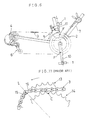
- Fig. 6 shows a bicycle drive system including a multi-gear cluster of the invention, which is constructed as a front gear or sprocket assembly 2.
- a bicycle rider applies his leg force to a pedal 1 thus to the multi-gear cluster 2, this force is transmitted through a drive chain 3 to a rear gear or sprocket cluster 4 and then to a rear wheel of the bicycle.
- a speed change operation is possible by shifting the chain 3 among the gears of the front and/or rear gear clusters 2 and 4, by means of a front derailleur 5 and a rear derailleur 6, respectively.
- the drive chain 3 as shown particularly in Figs. 2 through 4, comprises an endless chain loop consisting of pluralities of opposed pairs of roller links 3a each pair forming a relatively small clearance with the gear teeth and opposed pairs of pin links 3b each pair forming a relatively large clearance with the gear teeth, with the roller link pairs 3a and pin link pairs 3b being connected alterantely to one another to form the endless chain loop.
- the pin link pairs 3b provide the large clearance for facilitating a lateral, i.e. width-wise movement of the chain 3 needed for the chain shifting operation.
- Figs. 2 and 3 show only one lateral side of the chain 3.
- a hanger 8 of a bicycle frame close to the pedals rotatably supports a crank shaft 9 on which right and left crank arms 10, 11 are fixedly secured with 180 degree displacement therebetween for supporting the pedals 1, 1.
- an arm 10b extending radially from a boss 10a of the right crank arm 10 fixedly carries thereon a large gear 12, a middle gear 13 and a small gear 14 with predetermined axial distances therebetween, thus together constructing the multi-gear cluster 2.
- the leg input force from the pedals 1 to the multi-gear cluster 2 is minimum where the crank arms 10 and 11 are positioned substantially vertical as illustrated in Figs. 5 and 6.
- disengagement-facilitating areas F at two gear peripheral portions in these phases where the longitudinal axis of the crank arms 10 and 11 is located and the leg input force is minimum. That is to say, at the top and bottom dead points where the crank arms 10 and 11 are oriented substantially vertical, the leg input force is minimum thus the minimum tension acts on the chain 3.
- the disengagement-facilitating are F includes the above-mentioned disengagement-facilitating portion D for facilitating disengagement of the chain 3 from the teeth of the middle gear 13 and also displacement of the disengaged chain portion toward the small gear 14, a stopper portion S for coming into abutment against an inner face of a link 3b1 of a pin link pair 3b, the link 3b1 being opposed to the other link facing the small gear 14 (i.e. the link 3b1 faces the large gear 12) and a disengagement-assisting portion A for assisting the disengaging action of the chain 3 by the disengagement-facilitating portion D.
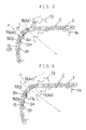
- the disengagement-facilitating area F includes first through third teeth 15, 16 and 17 having gradually increased tooth heights rearwardly relative to the rotational direction of the middle gear 13 (this side will be referred to as “the rear side” while the other side will be referred to as “the forward side”, hereinafter).
- the first tooth 15 has the relatively reduced tooth height so that this tooth 15 acts as the aforementioned disengagement-facilitating portion D for permiting or facilitating a 'riding' motion of the roller link pair 3a when the first tooth 15 comes into positional correspondance with the roller link pair 3a.
- the second tooth 16 has a slightly greater tooth height than the first tooth 15 so that this second tooth 16 acts as the stopper portion S for coming into abutment against the inner face of the link 3b1 of the pin link pair 3b facing the large gear when the second tooth 16 comes into positional correspondance with the pin link pair 3b.
- the third tooth 17 has a futher increased tooth height relative to the second tooth 16 so that this third tooth 17 allows the second tooth 16 to act as the disengagement-facilitating portion and also the third tooth 17 per se acts as the stopper portion S when the second tooth 16 comes into positional correspondence with the roller link pair 3a.
- the disengagement-assisting portion A serves to restrict disadvantageous interference between the middle gear 13 and the portion of the chain 3 displaced by the disengagement-facilitating portion D toward the small gear 14 relative to a central plane X of the teeth train. More specifically, as shown in Figs. 2 through 4, this disengagement-assisting portion A consists of a first disengagement-assisting part A1 comprising a chamferred lateral face 17a of the third tooth 17 facing the small gear 14 and of second and third disengagment-assisting parts A2 and A3 comprising fourth and fifth teeth 18 and 19 rearwardly of and having reduced tooth heights relative to the third tooth 17. That is, as illustrated in Figs.
- the teeth phase arrangement of the small gear 14 relative to the disengagement-facilitating portion D is predetermined with reference to the second tooth 16 positioned rearwardly of the first tooth 15 acting as the disengagement-facilitating portion D so that the chain 3 comes into engagement with the teeth of the small gear 14 at an area C where the above-described displaced chain portion is shifted toward the small gear 14.
- the second tooth 16 acts as a fixed pivot and the rear portion of the chain 3 relative to the preceeding chain portion corresponding to the second tooth 16 becomes free from engagement and moves close to the small gear 14. Then, since the second tooth 16 keeps acting as the fixed pivot for the above-described, disengaged and displaced chain portion until this chain portion comes into engagement with the teeth of the small gear 14, this engagement takes place accurately and reliably while the middle gear 13 effects a 180 degree rotation after the start of the change speed operation.
Abstract
Description
- The present invention relates to a multi-gear cluster for a bicycle, and more particularly to a multi-gear cluster having more than two gears of different diameters.
- Referring to Fig. 11 which shows a conventional multi-gear cluster, the prior art has provided various arrangements for facilitating a shifting movement of a
chain 3 from alarge gear 13 to an adjacentsmall gear 14 by e.g. cutting away top edges of someteeth large gear 13 or biasing these edges towards the small gear 14 (see the Japanese published patent gazette No. 56-3230). - Such conventional arrangements, however, have paid no consideration to the rotational phase relationship between the
teeth chain 3 displaced (by means of a derailleur) towards thesmall gear 14 from a center of thickness of thelarge gear 13 fails to engage the teeth of thesmall gear 14. 16 and just rides over the top edges of the teeth at a shifting position C. Then, a perfect engagement between thechain 3 and thesmall gear 14 occurs only after thelarge gear 13 rotates for a few times. This not only impairs a smooth chain shifting operation but also, in a worse case, causes a complete derailmement of the chain into the gap between the adjacent gear pair, thus completely disabling the entire bicycle drive system. - Taking the above-state of the art into consideration, the primary object of the present invention is to provide an improved multi-gear bluster for a bicycle which always permits a smooth and reliable chain shifting operation from the large gear to the small gear, the invention's cluter being superior also for being simple in construction and economical to manufacture.
-
- For accomplishing the above-noted object, a multi-gear cluster for a bicycle having at least two gears of different diameters, according to the first characterizing feature of the present invention, the larger gear includes at a peripheral part thereof a disengagement-facilitating portion for facilitating a disengaging motion of the drive chain from the teeth of the larger gear and also a subsequent shifting motion of the chain toward the smaller gear adjacent the larger gear; and, the teeth of the smaller gear are provided with a phase arrangement relative to the disengagement-facilitating portion such that the chain comes into engagement with the teeth of the smaller gear where a portion of the chain is displaced by the disengagement-facilitating portion toward the smaller gear from a center of thickness of the larger gear.
- Preferrably, according to the second characterizing feature of the invention, said disengagement-facilitating portion comprises a first tooth having a reduced height and a top ridge thereof displaced toward the smaller gear or a chamferred lateral face; and, the larger gear includes a second tooth rearwardly of the first tooth relative to a rotational direction of the gear cluster; the second tooth coming into abutment against an inner face of a link element of the displaced chain portion, the link element being opposed to the other link element adjacent the smaller gear; and the teeth phase arrangement of the smaller gear relative to the disengagement-facilitating portion being predetermined with reference to the second tooth. Functions and effects of the above-described features of the invention will be detailed next.
- According to the first characterizing feature of the invention, when a rider effects a change speed operation, the chain starts its lateral shifting motion at the engagement-facilitating portion. Then, since the teeth of the smaller gear are provided with the phase arrangement relative to the disengagement-facilitating portion such that the chain comes into engagement with the teeth of the smaller gear where the portion of the chain is displaced by the disengagement-facilitating portion toward the smaller gear from a center of thickness of the larger gear, the displaced chain portion quickly and reliably comes into engagement with the smaller gear teeth.
- Further, according to the second characterizing feature of the invention, since the disengagement-facilitating portion comprises a first tooth having a reduced height and a top ridge thereof displaced toward the smaller gear or a chamferred lateral face, this disengagement-facilitating portion can be formed easily and inexpensively. Also, since the larger gear includes a second tooth rearwardly of the first tooth relative to a rotational direction of the gear cluster and this second tooth comes into engagement with an inner face of a link element of the displaced chain portion, the link element being opposed to the other link element adjacent the smaller gear, this second tooth acts as a fixed pivot for the chain portion disengaged from the large gear teeth. Moreover, since the teeth phase arrangement of the smaller gear relative to the disengagement-facilitating portion is predetermined with reference to the second tooth, the displaced chain portion can reliably come into engagement with the smaller gear teeth regardless of possible irregularities in the operational amount of the derailleur.
- As described above, the displaced chain portion immediately and reliably comes into engagement with the smaller gear teeth. Therefore, the chain shifting operation for a change speed can be completed approximately within 180 degree rotation of the gear cluster. Thus, the invention has fully achieved the intended object of providing an improved multi-gear cluster for a bicycle which always permits a smooth and reliable chain shifting operation from the larger gear to the smaller gear, the cluter being superior also for being simple in construction and economical to manufacture.
- Further and other objects, features and effects of the invention will become more apparent from the following more detailed description of the embodiments of the invention with reference to the accompanying drawings.
- Accompanying drawings illustrate preferred embodiments of the present invention; in which,
- Fig. 1 is a side view illustrating a change speed condition of a multi-gear cluster for a bicycle,
- Figs. 2 and 3 are enlarged views showing major portions of the bicycle multi-gear cluster of Fig. 1,
- Fig. 4 is a plane view corresponding to Fig. 2,
- Fig. 5 is a section view showing the vicinity of the multi-gear cluster,
- Fig. 6 is a side view showing an entire bicycle drive system including the gear cluster, and
- Figs. 7 through 10 respectively illustrate further embodiments of the bicycle multi-gear cluster of the invention.
- Preferred embodiments of the invention will now be described in particular, with reference to Figs. 1 through 6.
- Fig. 6 shows a bicycle drive system including a multi-gear cluster of the invention, which is constructed as a front gear or
sprocket assembly 2. In this system, as a bicycle rider applies his leg force to apedal 1 thus to themulti-gear cluster 2, this force is transmitted through adrive chain 3 to a rear gear orsprocket cluster 4 and then to a rear wheel of the bicycle. A speed change operation is possible by shifting thechain 3 among the gears of the front and/orrear gear clusters front derailleur 5 and a rear derailleur 6, respectively. - The
drive chain 3, as shown particularly in Figs. 2 through 4, comprises an endless chain loop consisting of pluralities of opposed pairs ofroller links 3a each pair forming a relatively small clearance with the gear teeth and opposed pairs ofpin links 3b each pair forming a relatively large clearance with the gear teeth, with theroller link pairs 3a andpin link pairs 3b being connected alterantely to one another to form the endless chain loop. Thepin link pairs 3b provide the large clearance for facilitating a lateral, i.e. width-wise movement of thechain 3 needed for the chain shifting operation. Indidentally, Figs. 2 and 3 show only one lateral side of thechain 3. - Referring now to Fig. 5, a hanger 8 of a bicycle frame close to the pedals, rotatably supports a
crank shaft 9 on which right andleft crank arms pedals boss 10a of theright crank arm 10 fixedly carries thereon alarge gear 12, amiddle gear 13 and asmall gear 14 with predetermined axial distances therebetween, thus together constructing themulti-gear cluster 2. - In this particular embodiment, only the
middle gear 13 as generically representing the "larger", gear and the small gear as representing the "small" gear will be described. As is well-known from the biomechanical study, the leg input force from thepedals 1 to themulti-gear cluster 2 is minimum where thecrank arms crank arms crank arms chain 3. Therefore, the reduced tension makes it easier for thechain 3 to effect a lateral motion which is one requirement for a change speed operation. This helps disengagement-facilitating portions (to be detailed later) to fully achieve their function. It is also conceivable to provide the disengagement-facilitating area F at more than two gear peripheral portions depending on the convenience. The disengagement-facilitating are F includes the above-mentioned disengagement-facilitating portion D for facilitating disengagement of thechain 3 from the teeth of themiddle gear 13 and also displacement of the disengaged chain portion toward thesmall gear 14, a stopper portion S for coming into abutment against an inner face of a link 3b1 of apin link pair 3b, the link 3b1 being opposed to the other link facing the small gear 14 (i.e. the link 3b1 faces the large gear 12) and a disengagement-assisting portion A for assisting the disengaging action of thechain 3 by the disengagement-facilitating portion D. - More particularly, the disengagement-facilitating area F, as shown in Figs. 1 through 4, includes first through
third teeth first tooth 15 has the relatively reduced tooth height so that thistooth 15 acts as the aforementioned disengagement-facilitating portion D for permiting or facilitating a 'riding' motion of theroller link pair 3a when thefirst tooth 15 comes into positional correspondance with theroller link pair 3a. Thesecond tooth 16 has a slightly greater tooth height than thefirst tooth 15 so that thissecond tooth 16 acts as the stopper portion S for coming into abutment against the inner face of the link 3b1 of thepin link pair 3b facing the large gear when thesecond tooth 16 comes into positional correspondance with thepin link pair 3b. Further, as best shown in Fig. 3, thethird tooth 17 has a futher increased tooth height relative to thesecond tooth 16 so that thisthird tooth 17 allows thesecond tooth 16 to act as the disengagement-facilitating portion and also thethird tooth 17 per se acts as the stopper portion S when thesecond tooth 16 comes into positional correspondence with theroller link pair 3a. - The disengagement-assisting portion A serves to restrict disadvantageous interference between the
middle gear 13 and the portion of thechain 3 displaced by the disengagement-facilitating portion D toward thesmall gear 14 relative to a central plane X of the teeth train. More specifically, as shown in Figs. 2 through 4, this disengagement-assisting portion A consists of a first disengagement-assisting part A1 comprising a chamferredlateral face 17a of thethird tooth 17 facing thesmall gear 14 and of second and third disengagment-assisting parts A2 and A3 comprising fourth andfifth teeth third tooth 17. That is, as illustrated in Figs. 2 and 4, when thefirst tooth 15 comes into positional correspondence with theroller link pair 3a, the link 3a1 (facing the middle gear 13) of theroller link pair 3a runs beside the first disengagement-assisting portion A1 at thethird tooth 17 facing thesmall gear 14, so that the second disengagement-assisting part A2 prevents thepin link pair 3b succeeding to thelink pair 3a from engaging with thefourth tooth 18. On the other hand, as illustrated in Fig. 3, when theroller link pair 3b comes into positional correspondance with thesecond tooth 16, the second and third disengagement-assisting parts A2 and A3 serve to prevent theroller link pair 3a andpin link pair 3b from engaging the fourth andfifth teeth fourth tooth 18 be close to the phase where the longitudinal center line L of theright crank arm 10 is located. - If a change speed operation is effected when the
first tooth 15 corresponds to theroller link pair 3a, as shown in Figs. 2 and 4, the portion of thechain 3 rearward relative to that chain portion corresponding to thesecond tooth 16 does not engage with the teeth of themiddle gear 13 and is displaced toward thesmall gear 14 from the gear-thickness-wise center plane X of themiddle gear 13. In the course of this, as illustrated in Fig. 2, thesecond tooth 16 acts as a pivot for the disengaged and displaced chain portion. That is, in the present invention, the teeth phase arrangement of thesmall gear 14 relative to the disengagement-facilitating portion D is predetermined with reference to thesecond tooth 16 positioned rearwardly of thefirst tooth 15 acting as the disengagement-facilitating portion D so that thechain 3 comes into engagement with the teeth of thesmall gear 14 at an area C where the above-described displaced chain portion is shifted toward thesmall gear 14. - Further, with the invention's multi-gear cluster described above, two pairs respectively of the disengagement-facilitating portions D, stopper portions S and disengagement-assisting portions A are provided in each disengagement-facilitating area F with one pitch displacement therebetween. Therefore, as will de detailed later, a change speed operation can be reliably effected whether the
roller link pair 3a or thepin link pair 3b happens to correspond to thefirst tooth 15. - First, if the
chain 3 is pressed toward hesmall gear 14 by thefront derailleur 5 when theroller link pair 3a corresponds to thefirst tooth 15, as illustrated in Figs. 1, 2 and 4, thesecond tooth 16 acts as a fixed pivot and the rear portion of thechain 3 relative to the preceeding chain portion corresponding to thesecond tooth 16 becomes free from engagement and moves close to thesmall gear 14. Then, since thesecond tooth 16 keeps acting as the fixed pivot for the above-described, disengaged and displaced chain portion until this chain portion comes into engagement with the teeth of thesmall gear 14, this engagement takes place accurately and reliably while themiddle gear 13 effects a 180 degree rotation after the start of the change speed operation. - On other hand, if the above-described change speed operation is started when the
roller link pair 3a corresponds to thesecond tooth 16, i.e. when thepin link pair 3b corresponds to the first tooth, as illustrated in Fig. 3, the change speed operation is effected with thethird tooth 17 acting as the fixed pivot for the chain portion. In this case too, since the phase difference between thesecond tooth 16 and thethird tooth 17 is only one pitch amount, the engagement between the small gear teeth and the displaced chain portion takes place reliably as well. -
- Some other embodiments of the invention will be specifically described next.
- I. As shown in Figs. 7 and 8, it is conceivable to form the
second tooth 16 such that thistooth 16 has, on one side facing thelarge gear 12, aflat portion 16a of a tooth height substantially same as thefirst tooth 15 and has, on the other side facing thesmall gear 14, a projectingportion 16b as a fixed pivot for the displaced chain portion. With this arrangement, it becomes possible to minimize difference between the amount of displacement of thechain 3 toward themiddle gear 13 when theroller link pair 3a rides over the top of thefirst tooth 15 and that when theroller link pair 3a rides over theflat portion 16a; hence, it becomes possible to minimize pitch irrgularity between the small gear teeth and the displaced chain portion in these cases. Further, since thisflat portion 16a is positioned lower than the top of the second tooth of the foregoing embodiment, the riding motion of theroller link pair 3a and the subsequent disengagement of thechain 3 can be further facilitated. - II. Further, alterantely, as shown in Fig. 9, the first and
second teeth portions large gear 12. Or, as shown in Fig. 10, the first andsecond teeth tops small gear 14; that is, the tops 15d, 16d can be displaced in the opposite direction relative to tops 18d, 19d of the fourth andfifth teeth - III. As shown in Fig. 9, the fourth and
fifth teeth large gear 12. Or, as shown in Fig. 10, these fourth and fifth teeth can havechamferred portions small gear 14. Specific constructions of these teeth could be modified in any other way by those skilled in the art. - IV. In case the
first tooth 15 always corresponds to theroller link pair 3a or theroller link pair 3a and thepin link pair 3b have substantially the same width, it suffices for one disengagment-facilitating area F to have only one set of the disengagement-facilitating portion D, stopper portion S and the disengagement-assisting portion A. That is, it is also possible to form the disengagement-facilitating portion D by reducing the tooth height of only one tooth of themiddle gear 13. - V. If the
chain 3 can be displaced toward thesmall gear 14 by a sufficient amount by means of the disengagement-facilitating portion D alone, the disengagement-assisting portion A can be eliminated. - VI. In case the disengement-facilitating portion D is formed by cutting of teeth of the
middle gear 13 by a considerable amount and the portion D can no longer come into full engagement with thechain 3, a tooth positioned forwardly of this disengagement-facilitating portion D acts as the stopper portion S. That is to say, the specific position of the stopper portion S can be determined according to the particular construction of the disengagement-facilitating portion D. - VII. Aside from the middle and
small gears middle gears multi-gear cluster 4. - VIII. In the foregoing embodiments, the phase of the teeth of the small gear relative to the disengagement-facilitating portion is determined with reference to the
second tooth 16. Instead, the teeth phase can be determined with reference to thethird tooth 17. - IX. The disengagement-facilitating portions D, stopper portions S, disengagement-assisting portions D can be formed alternately by e.g. using jigs provided separately from the
middle gear 13, as well as by the tooth-cutting treatment of thisgear 13. - The invention may be embodied in other specific forms without departing from the spirit or essential characteristics thereof. The present embodiments are therefore to be considered in all respects as illustrative and not restrictive, the scope of the invention being indicated by the appended claims rather than by the foregoing description and all changes which come within the meaning and range of equivalency of the claims are therefore intended to be embraced therein.
Claims (8)
characterized in that
the larger gear includes at a peripheral part thereof a disengagement-facilitating portion (D) for facilitating a disengaging motion of a drive chain (3) from the teeth of the larger gear (13) and also a subsequent shifting motion of the chain (3) toward the smaller gear (14) adjacent the larger gear (13); the teeth of the smaller gear (14) being provided with a phase arrangement relative to said disengagement-facilitating portion (D) such that said chain (3) comes into engagement with the teeth of said smaller gear (14) at a position (C) where a portion of the chain (3) is displaced by the disengagement-facilitating portion (D) toward the smaller gear (14) front a center of thickness (X) of the larger gear (13).
characterized in that
said disengagement-facilitating portion (D) comprises a first tooth (15) of the larger gear (13) having a reduced height and a top ridge thereof displaced toward said smaller gear (14) or a chamferred lateral face; and, said larger gear (13) includes a second tooth (16) rearwardly of said first tooth (15) relative to a rotational direction of said gear cluster; said second tooth (16) coming into abutment against an inner face of a link element of said displaced chain portion, the link element being opposed to the other link element adjacent said smaller gear (14); and said teeth phase arrangement of the smaller gear (14) relative to said disengagement-facilitating portion (D) being predetermined with reference to said second tooth (16).
characterized in that
said second tooth (16) has a reduced height and a top ridge thereof displaced toward said smaller gear (14) or a chamferred lateral face, said second tooth (16) being provided separately from said first tooth (15) and constructed as said disengagement-facilitating portion (D) selectively operable with said first tooth (15); said cluster further comprising:
a third tooth (17) provided rearwardly of said second tooth (16) relative to the rotational direction of said larger gear (13), said third tooth (17) allowing said second tooth (16) to act as said disengagement-facilitating portion (D) while said third tooth (17) comes into abutment against an inner face of one link element of the displaced chain portion opposite to the other link element facing said smaller gear (14);
said teeth phase arrangement of the smaller gear (14) relative to said disengagement-facilitating portion (D) being predetermined with reference to said third tooth (17).
characterized in that
said first through third teeth (15), (16), (17) have gradually increased heights rearwardly relative to said rotational direction.
characterized by
a disengagement-assisting portion (A) for restricting interference between said larger gear (13) and said portion of the chain (3) displaced by said disengagement-facilitating portion (D) toward said smaller gear (14) relative to a central plane (X) of the teeth train.
characterized in that
said disengagement-assisting portion (A) includes a chamferred lateral face (17a) of said third tooth (17) facing said smaller gear (14) and fourth and fifth teeth (18), (19) provided rearwardly of and having reduced tooth heights relative to said third tooth (17).
characterized in that
said disengagement-facilitating portion (D) is provided at each of top and bottom dead points of crank arms of the bicycle.
characterized in that
said cluster comprises a front sprocket assembly having large, middle and small gears (12), (13), (14), said disengagement-facilitating portion (D) being provided to said middle gear (13) and said small gear (14), respectively.
Applications Claiming Priority (2)
| Application Number | Priority Date | Filing Date | Title |
|---|---|---|---|
| JP1236032A JP2939274B2 (en) | 1989-09-12 | 1989-09-12 | Multi-stage sprocket wheel for bicycle |
| JP236032/89 | 1989-09-12 |
Publications (2)
| Publication Number | Publication Date |
|---|---|
| EP0417696A1 true EP0417696A1 (en) | 1991-03-20 |
| EP0417696B1 EP0417696B1 (en) | 1995-01-25 |
Family
ID=16994751
Family Applications (1)
| Application Number | Title | Priority Date | Filing Date |
|---|---|---|---|
| EP90117397A Expired - Lifetime EP0417696B1 (en) | 1989-09-12 | 1990-09-10 | Multi-gear cluster for bicycle |
Country Status (4)
| Country | Link |
|---|---|
| US (1) | US5085620A (en) |
| EP (1) | EP0417696B1 (en) |
| JP (1) | JP2939274B2 (en) |
| DE (1) | DE69016320T2 (en) |
Cited By (8)
| Publication number | Priority date | Publication date | Assignee | Title |
|---|---|---|---|---|
| EP0505809A1 (en) * | 1991-03-29 | 1992-09-30 | Sakae Co., Ltd. | Multiple sprocket assembly for bicycle |
| EP0510361A1 (en) * | 1991-04-23 | 1992-10-28 | Mory Suntour Inc. | Multiple sprocket assembly for bicycle |
| DE4330989A1 (en) * | 1993-09-13 | 1995-03-16 | Fichtel & Sachs Ag | Derailleur gears, especially for bicycles |
| US5738603A (en) * | 1994-12-16 | 1998-04-14 | Fichtel & Sachs Ag | Derailleur |
| EP0945335A1 (en) * | 1998-03-26 | 1999-09-29 | Attilio Bartolozzi | Apparatus for changing gear ratio in bicycles |
| DE10256746A1 (en) * | 2002-12-05 | 2004-06-24 | Hans Helmig Gmbh | Circuit sprockets |
| EP2578486A1 (en) * | 2011-10-05 | 2013-04-10 | Shimano Inc. | Bicycle crank assembly |
| CN104760655A (en) * | 2014-01-07 | 2015-07-08 | 株式会社岛野 | Bicycle crank assembly |
Families Citing this family (22)
| Publication number | Priority date | Publication date | Assignee | Title |
|---|---|---|---|---|
| US5192249A (en) * | 1990-02-28 | 1993-03-09 | Shimano, Inc. | Multi-stage sprocket assembly for bicycle |
| JPH0667289U (en) * | 1993-03-09 | 1994-09-22 | 株式会社シマノ | Bicycle front gear unit and bicycle crank used in this front gear unit |
| US5350339A (en) * | 1993-03-10 | 1994-09-27 | Carmichael George H | Derailleur pulley for use with bicycle derailleur systems |
| US5577749A (en) * | 1994-07-11 | 1996-11-26 | Ross; Thomas | Twin gear drive assembly for a bicycle |
| US5782713A (en) * | 1995-12-06 | 1998-07-21 | Yang; Shu-Chiung C. | Bicycle gear crank arresting device |
| US6139456A (en) * | 1999-01-13 | 2000-10-31 | Lii; Jia-Miin | Bicycle sprocket |
| US6293884B1 (en) * | 1999-09-08 | 2001-09-25 | Chattin Cluster Gears, Inc. | Cluster sprockets for bicycle transmissions and other prime movers |
| US6340338B1 (en) * | 2000-09-13 | 2002-01-22 | Shimano Inc. | Bicycle sprocket |
| US6923741B2 (en) † | 2002-08-30 | 2005-08-02 | Shimano Inc. | Top sprocket for a rear sprocket assembly and rear sprocket assembly for a bicycle |
| DE10260565B4 (en) * | 2002-12-21 | 2016-09-15 | Sram Deutschland Gmbh | The sprocket assembly |
| US20040259674A1 (en) * | 2003-06-23 | 2004-12-23 | Pfister Dennis M. | Sprocket having variable height teeth |
| US8226511B2 (en) | 2005-01-08 | 2012-07-24 | Shimano, Inc. | Bicycle sprocket tooth with a shift assist radius greater than a reference tooth radius |
| US7334500B2 (en) * | 2005-05-17 | 2008-02-26 | Leon Tseng | Pedal crank having solid coupling |
| US20090111787A1 (en) * | 2007-10-31 | 2009-04-30 | Florencia Lim | Polymer blends for drug delivery stent matrix with improved thermal stability |
| JP5473662B2 (en) * | 2010-02-16 | 2014-04-16 | 株式会社椿本チエイン | Sprocket and transmission |
| DE102010039251B4 (en) * | 2010-08-12 | 2014-11-27 | Hirschvogel Umformtechnik Gmbh | Blank of a machine component, which includes teeth, as well as manufacturing method of such a machine component |
| US8978514B2 (en) * | 2012-07-10 | 2015-03-17 | Shimano Inc. | Bicycle front sprocket |
| DE102015219522A1 (en) * | 2014-10-14 | 2016-04-14 | Sram Deutschland Gmbh | Multiple sprocket assembly for a rear hub |
| US9631714B2 (en) | 2015-03-24 | 2017-04-25 | Shimano Inc. | Bicycle sprocket and bicycle crank assembly |
| US9885409B1 (en) | 2016-09-12 | 2018-02-06 | Shimano Inc. | Bicycle sprocket and bicycle rear sprocket assembly |
| US10933947B2 (en) * | 2017-09-15 | 2021-03-02 | Shimano Inc. | Bicycle sprocket |
| CN110077518B (en) * | 2019-04-15 | 2024-04-12 | 湖南速奥科技有限公司 | Dental tray, dental tray assembly and bicycle |
Citations (4)
| Publication number | Priority date | Publication date | Assignee | Title |
|---|---|---|---|---|
| EP0002903A1 (en) * | 1977-12-16 | 1979-07-11 | Shimano Industrial Company Limited | A multi-stage gear crank for a cycle |
| DE3037857A1 (en) * | 1979-10-11 | 1981-04-30 | Shimano Industrial Co., Ltd., Sakai, Osaka | SPROCKET SET FOR A BICYCLE GEAR |
| EP0034445A2 (en) * | 1980-02-13 | 1981-08-26 | Shimano Industrial Company Limited | Cycle gear crank |
| FR2638702A1 (en) * | 1988-11-07 | 1990-05-11 | Shimano Industrial Co | JUXTAPOSES SPROCKET ASSEMBLY FOR BICYCLE |
Family Cites Families (4)
| Publication number | Priority date | Publication date | Assignee | Title |
|---|---|---|---|---|
| JPS551989Y2 (en) * | 1976-12-28 | 1980-01-19 | ||
| FR2414044A1 (en) * | 1978-01-10 | 1979-08-03 | Pharmindustrie | NEW DERIVATIVES OF AZA-1 BICYCLO (2,2,2) OCTANE, USABLE AS MEDICINAL PRODUCTS |
| US4773893A (en) * | 1987-04-20 | 1988-09-27 | Te-Sheng Chang | Sprocket tooth speed varying sprocket assembly |
| FR2610279B3 (en) * | 1988-03-23 | 1989-02-10 | Hsu Yi Hsung | TEETH STRUCTURE FOR BICYCLE PINION |
-
1989
- 1989-09-12 JP JP1236032A patent/JP2939274B2/en not_active Expired - Fee Related
-
1990
- 1990-09-10 DE DE69016320T patent/DE69016320T2/en not_active Expired - Lifetime
- 1990-09-10 EP EP90117397A patent/EP0417696B1/en not_active Expired - Lifetime
- 1990-09-10 US US07/579,962 patent/US5085620A/en not_active Expired - Lifetime
Patent Citations (4)
| Publication number | Priority date | Publication date | Assignee | Title |
|---|---|---|---|---|
| EP0002903A1 (en) * | 1977-12-16 | 1979-07-11 | Shimano Industrial Company Limited | A multi-stage gear crank for a cycle |
| DE3037857A1 (en) * | 1979-10-11 | 1981-04-30 | Shimano Industrial Co., Ltd., Sakai, Osaka | SPROCKET SET FOR A BICYCLE GEAR |
| EP0034445A2 (en) * | 1980-02-13 | 1981-08-26 | Shimano Industrial Company Limited | Cycle gear crank |
| FR2638702A1 (en) * | 1988-11-07 | 1990-05-11 | Shimano Industrial Co | JUXTAPOSES SPROCKET ASSEMBLY FOR BICYCLE |
Cited By (13)
| Publication number | Priority date | Publication date | Assignee | Title |
|---|---|---|---|---|
| EP0505809A1 (en) * | 1991-03-29 | 1992-09-30 | Sakae Co., Ltd. | Multiple sprocket assembly for bicycle |
| US5188569A (en) * | 1991-03-29 | 1993-02-23 | Maeda Industries, Ltd. | Multiple sprocket assembly for bicycle |
| EP0510361A1 (en) * | 1991-04-23 | 1992-10-28 | Mory Suntour Inc. | Multiple sprocket assembly for bicycle |
| US5192250A (en) * | 1991-04-23 | 1993-03-09 | Maeda Industries, Ltd. | Multiple sprocket assembly for bicycle |
| DE4330989A1 (en) * | 1993-09-13 | 1995-03-16 | Fichtel & Sachs Ag | Derailleur gears, especially for bicycles |
| US5503598A (en) * | 1993-09-13 | 1996-04-02 | Fichtel & Sachs Ag | Derailleur arrangement, in particular for bicycles |
| US5738603A (en) * | 1994-12-16 | 1998-04-14 | Fichtel & Sachs Ag | Derailleur |
| EP0945335A1 (en) * | 1998-03-26 | 1999-09-29 | Attilio Bartolozzi | Apparatus for changing gear ratio in bicycles |
| AU738752B2 (en) * | 1998-03-26 | 2001-09-27 | Andrea Bartolozzi | Improved apparatus for changing gear ratio in bicycles, especially in race bicycles |
| DE10256746A1 (en) * | 2002-12-05 | 2004-06-24 | Hans Helmig Gmbh | Circuit sprockets |
| EP2578486A1 (en) * | 2011-10-05 | 2013-04-10 | Shimano Inc. | Bicycle crank assembly |
| US9771128B2 (en) | 2011-10-05 | 2017-09-26 | Shimano Inc. | Bicycle crank assembly |
| CN104760655A (en) * | 2014-01-07 | 2015-07-08 | 株式会社岛野 | Bicycle crank assembly |
Also Published As
| Publication number | Publication date |
|---|---|
| EP0417696B1 (en) | 1995-01-25 |
| JP2939274B2 (en) | 1999-08-25 |
| US5085620A (en) | 1992-02-04 |
| DE69016320D1 (en) | 1995-03-09 |
| JPH0399993A (en) | 1991-04-25 |
| DE69016320T2 (en) | 1995-05-18 |
Similar Documents
| Publication | Publication Date | Title |
|---|---|---|
| EP0417696B1 (en) | Multi-gear cluster for bicycle | |
| US5192249A (en) | Multi-stage sprocket assembly for bicycle | |
| US5123878A (en) | Multistage sprocket assembly | |
| US5192248A (en) | Multi-stage sprocket assembly for bicycle | |
| US5162022A (en) | Multiple sprocket assembly for bicycle | |
| US4592738A (en) | Chain gear for a bicycle | |
| EP0510361B1 (en) | Multiple sprocket assembly for bicycle | |
| US3815439A (en) | Multi-speed transmission front gear system | |
| US4889521A (en) | Multistage sprocket assembly for a bicycle | |
| EP0538780B1 (en) | Chain shift aiding structure for a bicycle sprocket assembly | |
| US4259880A (en) | Multi-stage gear crank for a bicycle | |
| US5133695A (en) | Bicycle multiple chainwheel | |
| US5078653A (en) | Multistep sprocket wheel device for a bicycle | |
| EP0386685B1 (en) | Bicycle multiple chainwheel | |
| US5188569A (en) | Multiple sprocket assembly for bicycle | |
| EP0130972A1 (en) | Automatic variable speed transmission | |
| JP3140026B2 (en) | Multi-stage sprocket device for bicycle | |
| US4955849A (en) | Front derailleur for use in bicycle | |
| JPH0239915Y2 (en) | ||
| EP0508328B2 (en) | Gear crank apparatus for a bicycle for supporting a plurality of chainwheels | |
| EP1386836A2 (en) | Bicycle derailleur with a chain guide | |
| US6948730B2 (en) | Bicycle with speed change gear | |
| JP2848834B2 (en) | Multi-stage gear crank for bicycle | |
| JPS6220398Y2 (en) | ||
| JP2688837B2 (en) | Multi-stage gear device |
Legal Events
| Date | Code | Title | Description |
|---|---|---|---|
| PUAI | Public reference made under article 153(3) epc to a published international application that has entered the european phase |
Free format text: ORIGINAL CODE: 0009012 |
|
| 17P | Request for examination filed |
Effective date: 19910102 |
|
| AK | Designated contracting states |
Kind code of ref document: A1 Designated state(s): AT BE CH DE DK ES FR GB GR IT LI LU NL SE |
|
| RBV | Designated contracting states (corrected) |
Designated state(s): DE FR GB IT |
|
| 17Q | First examination report despatched |
Effective date: 19930226 |
|
| RAP1 | Party data changed (applicant data changed or rights of an application transferred) |
Owner name: SHIMANO INC. |
|
| GRAA | (expected) grant |
Free format text: ORIGINAL CODE: 0009210 |
|
| ITF | It: translation for a ep patent filed |
Owner name: INTERPATENT ST.TECN. BREV. |
|
| AK | Designated contracting states |
Kind code of ref document: B1 Designated state(s): DE FR GB IT |
|
| REF | Corresponds to: |
Ref document number: 69016320 Country of ref document: DE Date of ref document: 19950309 |
|
| ET | Fr: translation filed | ||
| PLBE | No opposition filed within time limit |
Free format text: ORIGINAL CODE: 0009261 |
|
| STAA | Information on the status of an ep patent application or granted ep patent |
Free format text: STATUS: NO OPPOSITION FILED WITHIN TIME LIMIT |
|
| 26N | No opposition filed | ||
| REG | Reference to a national code |
Ref country code: GB Ref legal event code: IF02 |
|
| PGFP | Annual fee paid to national office [announced via postgrant information from national office to epo] |
Ref country code: GB Payment date: 20050907 Year of fee payment: 16 |
|
| GBPC | Gb: european patent ceased through non-payment of renewal fee |
Effective date: 20060910 |
|
| PG25 | Lapsed in a contracting state [announced via postgrant information from national office to epo] |
Ref country code: GB Free format text: LAPSE BECAUSE OF NON-PAYMENT OF DUE FEES Effective date: 20060910 |
|
| PGFP | Annual fee paid to national office [announced via postgrant information from national office to epo] |
Ref country code: DE Payment date: 20090903 Year of fee payment: 20 |
|
| PGFP | Annual fee paid to national office [announced via postgrant information from national office to epo] |
Ref country code: IT Payment date: 20090915 Year of fee payment: 20 Ref country code: FR Payment date: 20091012 Year of fee payment: 20 |
|
| PG25 | Lapsed in a contracting state [announced via postgrant information from national office to epo] |
Ref country code: DE Free format text: LAPSE BECAUSE OF EXPIRATION OF PROTECTION Effective date: 20100910 |