EP2578481A2 - Scooter - Google Patents
Scooter Download PDFInfo
- Publication number
- EP2578481A2 EP2578481A2 EP12185163.8A EP12185163A EP2578481A2 EP 2578481 A2 EP2578481 A2 EP 2578481A2 EP 12185163 A EP12185163 A EP 12185163A EP 2578481 A2 EP2578481 A2 EP 2578481A2
- Authority
- EP
- European Patent Office
- Prior art keywords
- scooter
- ball
- opposite
- ring
- footboard
- Prior art date
- Legal status (The legal status is an assumption and is not a legal conclusion. Google has not performed a legal analysis and makes no representation as to the accuracy of the status listed.)
- Withdrawn
Links
Images


Classifications
-
- B—PERFORMING OPERATIONS; TRANSPORTING
- B62—LAND VEHICLES FOR TRAVELLING OTHERWISE THAN ON RAILS
- B62K—CYCLES; CYCLE FRAMES; CYCLE STEERING DEVICES; RIDER-OPERATED TERMINAL CONTROLS SPECIALLY ADAPTED FOR CYCLES; CYCLE AXLE SUSPENSIONS; CYCLE SIDECARS, FORECARS, OR THE LIKE
- B62K15/00—Collapsible or foldable cycles
- B62K15/006—Collapsible or foldable cycles the frame being foldable
-
- B—PERFORMING OPERATIONS; TRANSPORTING
- B60—VEHICLES IN GENERAL
- B60B—VEHICLE WHEELS; CASTORS; AXLES FOR WHEELS OR CASTORS; INCREASING WHEEL ADHESION
- B60B19/00—Wheels not otherwise provided for or having characteristics specified in one of the subgroups of this group
-
- B—PERFORMING OPERATIONS; TRANSPORTING
- B60—VEHICLES IN GENERAL
- B60B—VEHICLE WHEELS; CASTORS; AXLES FOR WHEELS OR CASTORS; INCREASING WHEEL ADHESION
- B60B33/00—Castors in general ; Anti-clogging castors
- B60B33/0028—Construction of wheels; methods of assembling on axle
-
- B—PERFORMING OPERATIONS; TRANSPORTING
- B62—LAND VEHICLES FOR TRAVELLING OTHERWISE THAN ON RAILS
- B62K—CYCLES; CYCLE FRAMES; CYCLE STEERING DEVICES; RIDER-OPERATED TERMINAL CONTROLS SPECIALLY ADAPTED FOR CYCLES; CYCLE AXLE SUSPENSIONS; CYCLE SIDECARS, FORECARS, OR THE LIKE
- B62K3/00—Bicycles
- B62K3/002—Bicycles without a seat, i.e. the rider operating the vehicle in a standing position, e.g. non-motorized scooters; non-motorized scooters with skis or runners
Definitions
- the present application relates to a scooter, and particularly to a scooter having ball bearing wheels.
- a scooter including a footboard on which a rider can stand, a steering column having an upper end connected to a handlebar and a lower end connected to a front fork; a head-tube frame assembly having a head tube in which the lower end of the steering column is rotatably received and a frame assembly coupled to a front end of the footboard, a front wheel rotatably mounted to the front fork, and a rear wheel rotatably mounted to a rear fork provided at a rear end of the footboard wherein each of the front and rear wheels is in the form of a ball bearing wheel.
- Each ball bearing wheel may include an outer ring having an annular raceway formed on an inner surface thereof and an inner ring having an annular raceway formed on an outer surface thereof.
- the annular raceways are facing each other and defining an annular space.
- a plurality of bearing balls can be rotatably disposed around the annular space, and a ball-separating ring formed with a plurality of circumferentially spaced apart ball-retaining pockets for retaining therein the plurality of bearing balls respectively.
- the front fork may include two downwardly extending prongs, and the lower ends of the two prongs may be connected to two opposite sides of a lowermost portion of the inner ring respectively.
- the front fork can have two downwardly extending prongs, and the lower ends of the two prongs can be connected to two opposite sides of a radially inwardly extended portion formed on a lowermost portion of the inner ring respectively.
- the front fork may include two semi-circular-shaped prongs extending along two opposite sides of the outer and inner rings of the ball bearing wheel.
- the annular raceway of the outer ring and the annular raceway of the inner ring each may have an R-shaped cross section.
- Each ball-retaining pocket may be generally ⁇ -shaped.
- the outer ring may include an outer ground-engaging ring portion and an inner ball-engaging ring portion formed on an inner surface of the outer ground-engaging ring portion.
- the outer ground-engaging ring portion and the inner ball-engaging ring portion can be molded in one single piece.
- the outer ground-engaging ring portion may be made of polyurethane.
- the inner ball-engaging ring portion may be made of acrylonitride butadiene styrene.
- the inner ring may be made of acrylonitride butadiene styrene.
- the head-tube frame assembly may include two parallel arms having upper ends fixed to the head tube and lower ends pivotally coupled to a pivot pin provided on an upper surface of the footboard at the front end thereof.
- a tubular casing can be adapted to receive the two arms therethrough and two opposite projections can be formed on two opposite outer walls of the tubular casing respectively.
- a spring may have an upper end connected to the upper ends of the arms and a lower end connected to a lower end of the tubular casing.
- Two vertical walls can be formed on an upper surface of the footboard at the front end thereof. The two vertical walls may have two upper curved edges formed thereon with two opposite front slots and two opposite rear slots respectively.
- the two arms can be moved from an unfolded and locked position where the two opposite projections are inserted and biased by the spring into the two opposite front slots respectively, whereby pulling the tubular casing against the biasing force of the spring releases the two opposite projections from the two opposite front slots and allows the two arms to pivot about the pivot pin from the unfolded position, towards the footboard and to a folded and locked position where the two projections are inserted and biased by the spring into the two opposite rear slots respectively.
- a scooter including a footboard on which a rider can stand, a steering column having an upper end connected to a handlebar and a lower end connected to a front fork, a head-tube frame assembly having a head tube in which the lower end of the steering column is rotatably received and a frame assembly coupled to a front end of the footboard, a front ball bearing wheel rotatably mounted to the front fork, a rear ball bearing wheel rotatably mounted to a rear fork provided at a rear end of the footboard, two parallel arms having upper ends fixed to the head tube and lower ends pivotally coupled to a pivot pin provided on an upper surface of the footboard at the front end thereof, a tubular casing adapted to receive the two arms therethrough, two opposite projections being formed on two opposite outer walls of the tubular casing respectively, a spring having an upper end connected to the upper ends of the arms and a lower end connected to a lower end of the tubular casing, and two vertical walls formed on an upper surface of
- the two vertical walls may have two upper curved edges formed thereon with two opposite front slots and two opposite rear slots respectively, whereby the two arms can be moved from an unfolded and locked position where the two opposite projections are inserted and biased by the spring into the two opposite front slots respectively, and whereby pulling the tubular casing against the biasing force of the spring releases the two opposite projections from the two opposite front slots and allows the two arms to pivot about the pivot pin from the unfolded position, towards the footboard and to a folded and locked position where the two projections are inserted and biased by the spring into the two opposite rear slots respectively.
- Each of the front and rear ball bearing rings may include an outer ring having an annular raceway formed on an inner surface thereof, and an inner ring having an annular raceway formed on an outer surface thereof.
- the annular raceways can be facing each other and defining an annular space.
- a plurality of bearing balls can be rotatably disposed around the annular space, and a ball-separating ring can be formed with a plurality of circumferentially spaced apart ball-retaining pockets for retaining therein the plurality of bearing balls respectively.
- the front fork may include two downwardly extending prongs, and the lower ends of the two prongs can be connected to two opposite sides of a lowermost portion of the inner ring respectively.
- the front fork may include two semi-circular-shaped prongs extending along two opposite sides of the outer and inner rings of the ball bearing wheel.
- the annular raceway of the outer ring and the annular raceway of the inner ring each may have an R-shaped cross section.
- Each ball-retaining pocket may be generally ⁇ -shaped.
- the outer ring may include an outer ground-engaging ring portion and an inner ball-engaging ring portion formed on an inner surface of the outer ground-engaging ring portion.
- scooter disclosed in the present application is not limited to the precise embodiments described below and that various changes and modifications thereof may be effected by one skilled in the art without departing from the spirit or scope of the appended claims.
- elements and/or features of different illustrative embodiments may be combined with each other and/or substituted for each other within the scope of this disclosure and appended claims.
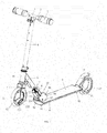
- FIG. 1 is a perspective view of a scooter according to an embodiment of the present application.
- the scooter may include a platform or footboard 9 on which a rider can stand.
- the footboard 9 has a front end 91 and a rear end 92.
- the scooter may include a steering column 4 having an upper end and a lower end.
- the upper end of the steering column 4 may be connected to a T-tube 1 having a horizontal tube portion and a downwardly depending portion.
- a horizontal handlebar 2 can be fixedly received in the horizontal tube portion of the T-tube 1.
- Two handles 3 can be fixedly coupled to the two opposite ends of the handlebar 2.
- the lower end of the steering column 4 can be connected to a front fork 5.
- a head-tube frame assembly 6, 8, 16 may include a head tube 16 in which the lower end of the steering column 4 can be rotatably received and a frame assembly 6, 8 coupled to the front end 91 of the footboard 9.
- a front ball bearing wheel 12 can be rotatably mounted to the front fork 5.
- the front fork 5 may have two downwardly extending prongs 51.
- the two prongs 51 of the front fork 5 may be generally semi-circular in shape, and extending along two opposite sides of the front ball bearing wheel 12.
- the two prongs 51 of the front fork 5 can serve as wheel covers for protecting the ball bearing wheel 12 and preventing a rider from accidentally touching the ball bearing wheel 12 during a ride.
- the two semi-circular prongs 51 can allow a central opening of the ball bearing wheel 12 to remain open without any obstruction.
- a rear ball bearing wheel 12' can be rotatably mounted to a rear fork 11 provided at the rear end 92 of the footboard 9.
- a cover or fender 10 may be provided at the rear end 92 of the footboard 9.
- the fender 10 may serve as a cover for the rear ball bearing wheel 12' as well as a braking device of the scooter.
- the fender 10 can be adapted to make contact with the rear ball bearing wheel 12' when the fender 10 is stepped down by a foot of the rider. When the fender 10 is stepped down and touches the rear ball bearing wheel 12', the friction between the fender 10 and the rear ball bearing wheel 12' causes the scooter to slow down and stop.
- the scooter has two wheels, it is understood that the scooter may have two or more wheels.
- the detailed structures of the front and rear ball bearing wheels 12, 12' will be described below.
- FIGS. 2a, 2b and 2c show different views of the front and rear ball bearing wheels 12, 12' of the scooter according to an embodiment of the present application.
- the structures of the front and rear ball bearing wheels 12, 12' can be substantially the same.
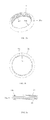
- the ball bearing wheel 12, 12' may include an outer ring 21 having an annular raceway R1 formed on an inner surface thereof, and an inner ring 22 having an annular raceway R2 formed on an outer surface thereof.
- the annular raceway R2 of the inner ring 22 can be facing the annular raceway R1 of the outer ring 21, and defining an annular space 28 thereinbetween.
- a plurality of bearing balls 24 can be rotatably disposed around the annular space 28.
- a ball-separating ring 25 may be formed with a plurality of ball-retaining pockets 27 for retaining therein the plurality of bearing balls 24 respectively.
- the ball-retaining pockets 27 may be equidistantly and circumferentially arranged along the ball-separating ring 25.
- the plurality of bearing balls 24 may be made of steel or any other suitable material.
- the two prongs 51 of the front fork 5 may extend along the two opposite sides of the outer and inner rings 21, 22 of the front ball bearing wheel 12.
- FIGS. 3a, 3b and 3c show different views of the outer ring 21 of the front and rear ball bearing wheels 12, 12' according to an embodiment of the present application.
- the outer ring 21 may be formed of an outer ground-engaging ring portion 21a and an inner ball-engaging ring portion 21b.
- the outer ground-engaging ring portion 21a can have a surface adapted to contact the ground when the scooter is moving thereon.
- the outer ground-engaging ring portion 21a may be made of polyurethane (PU) or any other suitable elastic material.
- the inner ball-engaging ring portion 21b is formed with the annular raceway R1 which can be configured to engage with the plurality of bearing balls 24.
- the inner ball-engaging ring portion 21b may be made of acrylonitride butadiene styrene (ABS) or any other suitable hard material.
- the annular raceway R1 of the outer rings 21 may have an R-shaped cross section.
- the outer ground-engaging ring portion 21a and the inner ball-engaging ring portion 21b can be molded in one single piece.
- FIGS. 4a, 4b and 4c show different views of the inner ring 22 of the front and rear ball bearing wheels 12, 12' according to an embodiment of the present application.
- the inner ring 22 with the annular raceway R2 formed thereon can be configured to engage with the plurality of bearings balls 24.
- the annular raceway R2 of the inner ring 22 may have an R-shaped cross section.
- the inner ring 22 may also be made of ABS or any other suitable hard material.
- the two lower ends of the two prongs 51 of the front fork 5 can be fixedly connected to two opposite sides of a lowermost portion of the inner ring 22 close to the ground respectively.
- the inner surface of the lowermost portion of the inner ring 22 can be formed with a radially inwardly extended portion 222.
- the extended portion 222 may be formed with two transverse through holes 223.
- Two sets of bolts and nuts 224 can be used to fasten the lower ends of the two prongs 51 to the extended portion 222 of the inner ring 22 through the two transverse through holes 223.
- the connection of the front fork 5 at the lowermost portion of the inner ring 22 close to the ground can make steering of the front ball bearing wheel 12 easier and riding on the scooter steadier.
- FIG. 5 illustrates the assembled outer and inner rings 21, 22 of the ball bearing wheels 12, 12'.
- the annular raceway R2 of the inner ring 22 can be facing the annular raceway R1 of the outer ring 21, and defining the annular space 28 for receiving therein the plurality of bearing balls 24.
- FIGS. 6a, 6b and 6c show different views of an annular shield 23 of the ball bearing wheels 12, 12' according to an embodiment of the present application.
- the annular shield 23 may have a plurality of screw holes 231 formed thereon. According to the illustrated embodiment, there can be three screw holes 231 formed on the annular shield 23.
- the annular shield 23 can be fastened on one side of the inner ring 22 by driving screws 26 through the screw holes 231 and into corresponding internally threaded portions 221 of the inner ring 22.
- FIGS. 7a, 7b and 7c show different views of the ball-separating ring 25 of the ball bearing wheels 12, 12' according to an embodiment of the present application.
- the ball-separating ring 25 may be formed with a plurality of circumferentially spaced apart ball-retaining pockets 27 for retaining therein the plurality of bearing balls 24 respectively.
- Each ball-retaining pocket 27 may have a generally ⁇ -shape.
- FIG. 8 illustrates the positioning of six bearing balls 24 on the ball-separating ring 25 of FIG. 7a . It can be seen that each bearing ball 24 can be retained in the ⁇ -shaped ball-retaining pocket 27 formed on the ball-separating frame 25.
- FIG. 9 is a cross sectional view of a fully assembled ball bearing wheel 12, 12'.
- the annular shield 23 can cover one side of the annular space 28 between the outer and inner rings 21, 22 of the ball bearing wheel 12, 12'.
- the outer ring 21 can rotate relative to the inner ring 22.
- the scooter of the present application may further include a folding mechanism in the head-tube frame assembly 6, 8, 16 for folding up the scooter.
- the head-tube frame assembly 6, 8, 16 (partially exploded) may have two parallel arms 6 having two upper ends fixed to the head tube 16 and two lower ends pivotally coupled to a pivot pin 81 provided on an upper surface of the footboard 9 at the front end 91 thereof.
- the two arms 6 can be received in a tubular casing 8.
- the tubular casing 8 may have a rectangular cross section.
- Two opposite projections 82 can be formed on two opposite outer walls of the tubular casing 8 respectively.
- a spring 7 can an upper end connected to the upper ends of the arms 6, and a lower end connected to a lower end of the tubular casing 8.
- Two vertical walls 83 can be formed on an upper surface of the footboard 9 at the front end 91 thereof.
- the two vertical walls 83 may have two upper curved edges 84 formed thereon with two opposite front slots 85 and two opposite rear slots 86 respectively.
- the two arms 6 of the head tube 16 can be moved from an unfolded and locked position where the two opposite projections 82 are inserted and biased by the spring 7 into the two opposite front slots 85 of the two vertical walls 83 respectively.
- Pulling the tubular casing 8 against the biasing force of the spring 7 can release the two opposite projections 82 from the two opposite front slots 85 respectively allowing the two arms 6 to pivot about the pivot pin 81 from the unfolded position towards the footboard 9 to a folded and locked position where the two opposite projections 82 can be inserted and biased by the spring 7 into the two opposite rear slots 86 of the two vertical wall 83 respectively.
- This folding mechanism serves to fold the steering column 4 together with the handlebar 2, the front fork 5 and the front ball bearing wheel 12 from the unfolded position to a folded position where the steering column 4 is disposed generally parallel to the footboard 9 for easy carrying and storage.
- a rider places one foot on the footboard 9 and uses the other foot to push off the scooter. Since the inner ring 22 is fixedly connected to the steering column 4 and the front fork 5, the inner ring 22 is stationary relative to the steering column 4 and the front fork 5. When the scooter is pushed forwards, the inner ring 22 moves forwards thereby driving the outer ring 21 and the plurality of balls 24 to rotate. When the outer ring 21 rotates, the scooter can then moves forwards.
- the scooter with the ball bearing wheels 12, 12' of the present application can have an unconventional outer appearance.
- Each ball bearing wheel 12, 12' has a central bore defined by the inner ring 22.
- the front and rear ball bearing wheels 12, 12' of the present application can give a scooter a new and unique look that can make the scooter more fun to play with by kids. Since there are no rotating axle, hub and spokes and less exposing moving parts as in a conventional wheel, the scooter of the present application is safer to play with. Furthermore, the scooter of the present application is simple in construction and low in manufacturing cost.
Landscapes
- Engineering & Computer Science (AREA)
- Mechanical Engineering (AREA)
- Rolling Contact Bearings (AREA)
- Motorcycle And Bicycle Frame (AREA)
- Steering Devices For Bicycles And Motorcycles (AREA)
Abstract
Description
- This application claims priority of
U.S. Provisional Patent Application No. 61/543,794 filed on October 5, 2011 - The present application relates to a scooter, and particularly to a scooter having ball bearing wheels.
- Traditional two-wheeled scooters have front and rear wheels. Each wheel is rotatably mounted on a central wheel axle within a wheel hub. These wheels have been used for many years. It is desirable to produce an improved scooter with wheels that have no central wheel axles and hubs, and to produce a scooter that is simple in construction, low in manufacturing cost and fun to play with.
- The above description of the background is provided to aid in understanding a scooter, but is not admitted to describe or constitute pertinent prior art to the scooter disclosed in the present application, or consider any cited documents as material to the patentability of the claims of the present application.
- According to one aspect, there is provided a scooter including a footboard on which a rider can stand, a steering column having an upper end connected to a handlebar and a lower end connected to a front fork; a head-tube frame assembly having a head tube in which the lower end of the steering column is rotatably received and a frame assembly coupled to a front end of the footboard, a front wheel rotatably mounted to the front fork, and a rear wheel rotatably mounted to a rear fork provided at a rear end of the footboard wherein each of the front and rear wheels is in the form of a ball bearing wheel.
- Each ball bearing wheel may include an outer ring having an annular raceway formed on an inner surface thereof and an inner ring having an annular raceway formed on an outer surface thereof. The annular raceways are facing each other and defining an annular space. A plurality of bearing balls can be rotatably disposed around the annular space, and a ball-separating ring formed with a plurality of circumferentially spaced apart ball-retaining pockets for retaining therein the plurality of bearing balls respectively.
- The front fork may include two downwardly extending prongs, and the lower ends of the two prongs may be connected to two opposite sides of a lowermost portion of the inner ring respectively. According to one embodiment, the front fork can have two downwardly extending prongs, and the lower ends of the two prongs can be connected to two opposite sides of a radially inwardly extended portion formed on a lowermost portion of the inner ring respectively. The front fork may include two semi-circular-shaped prongs extending along two opposite sides of the outer and inner rings of the ball bearing wheel.
- In one embodiment, the annular raceway of the outer ring and the annular raceway of the inner ring each may have an R-shaped cross section. Each ball-retaining pocket may be generally Ω-shaped.
- In one embodiment, the outer ring may include an outer ground-engaging ring portion and an inner ball-engaging ring portion formed on an inner surface of the outer ground-engaging ring portion. The outer ground-engaging ring portion and the inner ball-engaging ring portion can be molded in one single piece. The outer ground-engaging ring portion may be made of polyurethane. The inner ball-engaging ring portion may be made of acrylonitride butadiene styrene. The inner ring may be made of acrylonitride butadiene styrene.
- In one embodiment, the head-tube frame assembly may include two parallel arms having upper ends fixed to the head tube and lower ends pivotally coupled to a pivot pin provided on an upper surface of the footboard at the front end thereof. A tubular casing can be adapted to receive the two arms therethrough and two opposite projections can be formed on two opposite outer walls of the tubular casing respectively. A spring may have an upper end connected to the upper ends of the arms and a lower end connected to a lower end of the tubular casing. Two vertical walls can be formed on an upper surface of the footboard at the front end thereof. The two vertical walls may have two upper curved edges formed thereon with two opposite front slots and two opposite rear slots respectively. The two arms can be moved from an unfolded and locked position where the two opposite projections are inserted and biased by the spring into the two opposite front slots respectively, whereby pulling the tubular casing against the biasing force of the spring releases the two opposite projections from the two opposite front slots and allows the two arms to pivot about the pivot pin from the unfolded position, towards the footboard and to a folded and locked position where the two projections are inserted and biased by the spring into the two opposite rear slots respectively.
- According to another aspect, there is provided a scooter including a footboard on which a rider can stand, a steering column having an upper end connected to a handlebar and a lower end connected to a front fork, a head-tube frame assembly having a head tube in which the lower end of the steering column is rotatably received and a frame assembly coupled to a front end of the footboard, a front ball bearing wheel rotatably mounted to the front fork, a rear ball bearing wheel rotatably mounted to a rear fork provided at a rear end of the footboard, two parallel arms having upper ends fixed to the head tube and lower ends pivotally coupled to a pivot pin provided on an upper surface of the footboard at the front end thereof, a tubular casing adapted to receive the two arms therethrough, two opposite projections being formed on two opposite outer walls of the tubular casing respectively, a spring having an upper end connected to the upper ends of the arms and a lower end connected to a lower end of the tubular casing, and two vertical walls formed on an upper surface of the footboard at the front end thereof. The two vertical walls may have two upper curved edges formed thereon with two opposite front slots and two opposite rear slots respectively, whereby the two arms can be moved from an unfolded and locked position where the two opposite projections are inserted and biased by the spring into the two opposite front slots respectively, and whereby pulling the tubular casing against the biasing force of the spring releases the two opposite projections from the two opposite front slots and allows the two arms to pivot about the pivot pin from the unfolded position, towards the footboard and to a folded and locked position where the two projections are inserted and biased by the spring into the two opposite rear slots respectively.
- Each of the front and rear ball bearing rings may include an outer ring having an annular raceway formed on an inner surface thereof, and an inner ring having an annular raceway formed on an outer surface thereof. The annular raceways can be facing each other and defining an annular space. A plurality of bearing balls can be rotatably disposed around the annular space, and a ball-separating ring can be formed with a plurality of circumferentially spaced apart ball-retaining pockets for retaining therein the plurality of bearing balls respectively.
- In one embodiment, the front fork may include two downwardly extending prongs, and the lower ends of the two prongs can be connected to two opposite sides of a lowermost portion of the inner ring respectively. The front fork may include two semi-circular-shaped prongs extending along two opposite sides of the outer and inner rings of the ball bearing wheel.
- In one embodiment, the annular raceway of the outer ring and the annular raceway of the inner ring each may have an R-shaped cross section. Each ball-retaining pocket may be generally Ω-shaped. The outer ring may include an outer ground-engaging ring portion and an inner ball-engaging ring portion formed on an inner surface of the outer ground-engaging ring portion.
- Although the scooter disclosed in the present application is shown and described with respect to certain embodiments, it is obvious that equivalents and modifications will occur to others skilled in the art upon the reading and understanding of the specification. The present application includes all such equivalents and modifications, and is limited only by the scope of the claims.
- Specific embodiments of the scooter disclosed in the present application will now be described by way of example with reference to the accompanying drawings wherein:
-
FIG. 1 is a perspective view of a scooter according to an embodiment of the present application. -
FIG. 2a is an exploded view of a ball bearing wheel according to an embodiment of the present application. -
FIG. 2b is a cross sectional view of an assembled ball bearing wheel ofFIG. 2a . -
FIG. 2c is another cross sectional view of an assembled ball bearing wheel ofFIG. 2a . -
FIG. 3a is a perspective view of an outer ring of the ball bearing wheel according to an embodiment of the present application. -
FIG. 3b is a side view of the outer ring ofFIG. 3a . -
FIG. 3c is a cross sectional view of the outer ring ofFIG. 3a . -
FIG. 4a is a perspective view of an inner ring of the ball bearing wheel according to an embodiment of the present application. -
FIG. 4b is a side view of the inner ring ofFIG. 4a . -
FIG. 4c is a cross sectional view of the inner ring ofFIG. 4a . -
FIG. 5 is a cross sectional view showing the assembled outer and inner rings of the ball bearing wheel. -
FIG. 6a is a perspective view of an annular shield of the ball bearing wheel according to an embodiment of the present application. -
FIG. 6b is a side view of the annular shield ofFIG. 6a . -
FIG. 6c is a cross sectional view of the annular shield ofFIG. 6a . -
FIG. 7a is a perspective view of a ball-separating ring of the ball bearing wheel according to an embodiment of the present application. -
FIG. 7b is a side view of the ball-separating ring ofFIG. 7a . -
FIG. 7c is a cross sectional view of the ball-separating ring ofFIG. 7a . -
FIG. 8 is a perspective view illustrating the positioning of six bearing balls on the ball-separating ring ofFIG. 7a . -
FIG. 9 is a cross sectional view of a fully assembled ball bearing wheel of the present application. - Reference will now be made in detail to a preferred embodiment of the scooter disclosed in the present application, examples of which are also provided in the following description. Exemplary embodiments of the scooter disclosed in the present application are described in detail, although it will be apparent to those skilled in the relevant art that some features that are not particularly important to an understanding of the scooter may not be shown for the sake of clarity.
- Furthermore, it should be understood that the scooter disclosed in the present application is not limited to the precise embodiments described below and that various changes and modifications thereof may be effected by one skilled in the art without departing from the spirit or scope of the appended claims. For example, elements and/or features of different illustrative embodiments may be combined with each other and/or substituted for each other within the scope of this disclosure and appended claims.
- It should be noted that throughout the specification and claims herein, when one element is said to be "coupled" or "connected" to another, this does not necessarily mean that one element is fastened, secured, or otherwise attached to another element. Instead, the term "coupled" or "connected" means that one element is either connected directly or indirectly to another element, or is in mechanical or electrical communication with another element.
- Certain terminology is used in the following description for convenience only and is not limiting. The words "front", "rear", "upper", "lower", "upward", and "downward" designate directions in the drawings to which reference is made. The terminology includes the words noted above as well as derivatives thereof and words of similar import.
-
FIG. 1 is a perspective view of a scooter according to an embodiment of the present application. The scooter may include a platform orfootboard 9 on which a rider can stand. Thefootboard 9 has afront end 91 and arear end 92. The scooter may include asteering column 4 having an upper end and a lower end. - The upper end of the
steering column 4 may be connected to a T-tube 1 having a horizontal tube portion and a downwardly depending portion. Ahorizontal handlebar 2 can be fixedly received in the horizontal tube portion of the T-tube 1. Twohandles 3 can be fixedly coupled to the two opposite ends of thehandlebar 2. - The lower end of the
steering column 4 can be connected to afront fork 5. A head-tube frame assembly head tube 16 in which the lower end of thesteering column 4 can be rotatably received and aframe assembly front end 91 of thefootboard 9. A frontball bearing wheel 12 can be rotatably mounted to thefront fork 5. Thefront fork 5 may have two downwardly extendingprongs 51. The twoprongs 51 of thefront fork 5 may be generally semi-circular in shape, and extending along two opposite sides of the frontball bearing wheel 12. The twoprongs 51 of thefront fork 5 can serve as wheel covers for protecting theball bearing wheel 12 and preventing a rider from accidentally touching theball bearing wheel 12 during a ride. Furthermore, the twosemi-circular prongs 51 can allow a central opening of theball bearing wheel 12 to remain open without any obstruction. - A rear ball bearing wheel 12' can be rotatably mounted to a
rear fork 11 provided at therear end 92 of thefootboard 9. A cover orfender 10 may be provided at therear end 92 of thefootboard 9. Thefender 10 may serve as a cover for the rear ball bearing wheel 12' as well as a braking device of the scooter. Thefender 10 can be adapted to make contact with the rear ball bearing wheel 12' when thefender 10 is stepped down by a foot of the rider. When thefender 10 is stepped down and touches the rear ball bearing wheel 12', the friction between thefender 10 and the rear ball bearing wheel 12' causes the scooter to slow down and stop. - Although it has been shown and described that the scooter has two wheels, it is understood that the scooter may have two or more wheels. The detailed structures of the front and rear
ball bearing wheels 12, 12' will be described below. -
FIGS. 2a, 2b and 2c show different views of the front and rearball bearing wheels 12, 12' of the scooter according to an embodiment of the present application. The structures of the front and rearball bearing wheels 12, 12' can be substantially the same. - The
ball bearing wheel 12, 12' may include anouter ring 21 having an annular raceway R1 formed on an inner surface thereof, and aninner ring 22 having an annular raceway R2 formed on an outer surface thereof. The annular raceway R2 of theinner ring 22 can be facing the annular raceway R1 of theouter ring 21, and defining anannular space 28 thereinbetween. - A plurality of bearing
balls 24 can be rotatably disposed around theannular space 28. A ball-separatingring 25 may be formed with a plurality of ball-retainingpockets 27 for retaining therein the plurality of bearingballs 24 respectively. The ball-retainingpockets 27 may be equidistantly and circumferentially arranged along the ball-separatingring 25. The plurality of bearingballs 24 may be made of steel or any other suitable material. The twoprongs 51 of thefront fork 5 may extend along the two opposite sides of the outer andinner rings ball bearing wheel 12.FIGS. 3a, 3b and 3c show different views of theouter ring 21 of the front and rearball bearing wheels 12, 12' according to an embodiment of the present application. - The
outer ring 21 may be formed of an outer ground-engagingring portion 21a and an inner ball-engagingring portion 21b. The outer ground-engagingring portion 21a can have a surface adapted to contact the ground when the scooter is moving thereon. The outer ground-engagingring portion 21a may be made of polyurethane (PU) or any other suitable elastic material. The inner ball-engagingring portion 21b is formed with the annular raceway R1 which can be configured to engage with the plurality of bearingballs 24. The inner ball-engagingring portion 21b may be made of acrylonitride butadiene styrene (ABS) or any other suitable hard material. The annular raceway R1 of theouter rings 21 may have an R-shaped cross section. The outer ground-engagingring portion 21a and the inner ball-engagingring portion 21b can be molded in one single piece. -
FIGS. 4a, 4b and 4c show different views of theinner ring 22 of the front and rearball bearing wheels 12, 12' according to an embodiment of the present application. - The
inner ring 22 with the annular raceway R2 formed thereon can be configured to engage with the plurality ofbearings balls 24. Similarly, the annular raceway R2 of theinner ring 22 may have an R-shaped cross section. Theinner ring 22 may also be made of ABS or any other suitable hard material. - It can be seen in
FIG. 1 that the two lower ends of the twoprongs 51 of thefront fork 5 can be fixedly connected to two opposite sides of a lowermost portion of theinner ring 22 close to the ground respectively. According to the illustrated embodiment, the inner surface of the lowermost portion of theinner ring 22 can be formed with a radially inwardly extendedportion 222. Theextended portion 222 may be formed with two transverse throughholes 223. Two sets of bolts andnuts 224 can be used to fasten the lower ends of the twoprongs 51 to theextended portion 222 of theinner ring 22 through the two transverse throughholes 223. The connection of thefront fork 5 at the lowermost portion of theinner ring 22 close to the ground can make steering of the frontball bearing wheel 12 easier and riding on the scooter steadier. -
FIG. 5 illustrates the assembled outer andinner rings ball bearing wheels 12, 12'. When the outer andinner rings inner ring 22 can be facing the annular raceway R1 of theouter ring 21, and defining theannular space 28 for receiving therein the plurality of bearingballs 24. -
FIGS. 6a, 6b and 6c show different views of anannular shield 23 of theball bearing wheels 12, 12' according to an embodiment of the present application. Theannular shield 23 may have a plurality of screw holes 231 formed thereon. According to the illustrated embodiment, there can be threescrew holes 231 formed on theannular shield 23. Theannular shield 23 can be fastened on one side of theinner ring 22 by drivingscrews 26 through the screw holes 231 and into corresponding internally threadedportions 221 of theinner ring 22. -
FIGS. 7a, 7b and 7c show different views of the ball-separatingring 25 of theball bearing wheels 12, 12' according to an embodiment of the present application. The ball-separatingring 25 may be formed with a plurality of circumferentially spaced apart ball-retainingpockets 27 for retaining therein the plurality of bearingballs 24 respectively. According to the illustrated embodiment, there may be six ball-retainingpockets 27 formed on the ball-separatingring 25, though it can have more or less than six ball-retainingpockets 27. Each ball-retainingpocket 27 may have a generally Ω-shape. -
FIG. 8 illustrates the positioning of six bearingballs 24 on the ball-separatingring 25 ofFIG. 7a . It can be seen that each bearingball 24 can be retained in the Ω-shaped ball-retainingpocket 27 formed on the ball-separatingframe 25. -
FIG. 9 is a cross sectional view of a fully assembledball bearing wheel 12, 12'. As best illustrated in this figure, theannular shield 23 can cover one side of theannular space 28 between the outer andinner rings ball bearing wheel 12, 12'. By means of the plurality of bearingballs 24, theouter ring 21 can rotate relative to theinner ring 22. - The scooter of the present application may further include a folding mechanism in the head-
tube frame assembly FIG. 1 , the head-tube frame assembly parallel arms 6 having two upper ends fixed to thehead tube 16 and two lower ends pivotally coupled to apivot pin 81 provided on an upper surface of thefootboard 9 at thefront end 91 thereof. The twoarms 6 can be received in atubular casing 8. Thetubular casing 8 may have a rectangular cross section. Twoopposite projections 82 can be formed on two opposite outer walls of thetubular casing 8 respectively. Aspring 7 can an upper end connected to the upper ends of thearms 6, and a lower end connected to a lower end of thetubular casing 8. - Two
vertical walls 83 can be formed on an upper surface of thefootboard 9 at thefront end 91 thereof. The twovertical walls 83 may have two uppercurved edges 84 formed thereon with two oppositefront slots 85 and two oppositerear slots 86 respectively. - By means of the folding mechanism, the two
arms 6 of thehead tube 16 can be moved from an unfolded and locked position where the twoopposite projections 82 are inserted and biased by thespring 7 into the two oppositefront slots 85 of the twovertical walls 83 respectively. Pulling thetubular casing 8 against the biasing force of thespring 7 can release the twoopposite projections 82 from the two oppositefront slots 85 respectively allowing the twoarms 6 to pivot about thepivot pin 81 from the unfolded position towards thefootboard 9 to a folded and locked position where the twoopposite projections 82 can be inserted and biased by thespring 7 into the two oppositerear slots 86 of the twovertical wall 83 respectively. This folding mechanism serves to fold thesteering column 4 together with thehandlebar 2, thefront fork 5 and the frontball bearing wheel 12 from the unfolded position to a folded position where thesteering column 4 is disposed generally parallel to thefootboard 9 for easy carrying and storage. - To begin a ride, a rider places one foot on the
footboard 9 and uses the other foot to push off the scooter. Since theinner ring 22 is fixedly connected to thesteering column 4 and thefront fork 5, theinner ring 22 is stationary relative to thesteering column 4 and thefront fork 5. When the scooter is pushed forwards, theinner ring 22 moves forwards thereby driving theouter ring 21 and the plurality ofballs 24 to rotate. When theouter ring 21 rotates, the scooter can then moves forwards. - Without the central wheel axle and wheel hub of a conventional wheel, the scooter with the
ball bearing wheels 12, 12' of the present application can have an unconventional outer appearance. Eachball bearing wheel 12, 12' has a central bore defined by theinner ring 22. The front and rearball bearing wheels 12, 12' of the present application can give a scooter a new and unique look that can make the scooter more fun to play with by kids. Since there are no rotating axle, hub and spokes and less exposing moving parts as in a conventional wheel, the scooter of the present application is safer to play with. Furthermore, the scooter of the present application is simple in construction and low in manufacturing cost. - While the scooter disclosed in the present application has been shown and described with particular references to a number of preferred embodiments thereof, it should be noted that various other changes or modifications may be made without departing from the scope of the appending claims.
Claims (15)
- A scooter comprising:(a) a footboard on which a rider can stand;(b) a steering column having an upper end connected to a handlebar and a lower end connected to a front fork;(c) a head-tube frame assembly having a head tube in which the lower end of the steering column is rotatably received, and a frame assembly coupled to a front end of the footboard;(d) a front wheel rotatably mounted to the front fork; and(e) a rear wheel rotatably mounted to a rear fork provided at a rear end of the footboard;(f) wherein each of the front and rear wheels is in the form of a ball bearing wheel.
- The scooter as claimed in claim 1, wherein the ball bearing wheel comprises:(a) an outer ring having an annular raceway formed on an inner surface thereof;(b) an inner ring having an annular raceway formed on an outer surface thereof, the annular raceways facing each other and defining an annular space;(c) a plurality of bearing balls rotatably disposed around the annular space; and(d) a ball-separating ring formed with a plurality of circumferentially spaced apart ball-retaining pockets for retaining therein the plurality of bearing balls respectively.
- The scooter as claimed in claim 2, wherein the front fork comprises two downwardly extending prongs, and the lower ends of the two prongs are connected to two opposite sides of a lowermost portion of the inner ring respectively.
- The scooter as claimed in claim 2, wherein the front fork comprises two downwardly extending prongs, and the lower ends of the two prongs are connected to two opposite sides of a radially inwardly extended portion formed on a lowermost portion of the inner ring respectively.
- The scooter as claimed in claim 2, wherein the front fork comprises two semi-circular-shaped prongs extending along two opposite sides of the outer and inner rings of the ball bearing wheel.
- The scooter as claimed in claim 2, wherein the annular raceway of the outer ring and the annular raceway of the inner ring each have an R-shaped cross section.
- The scooter as claimed in claim 2, wherein each ball-retaining pocket is generally Ω-shaped.
- The scooter as claimed in claim 2, wherein the inner ring is made of acrylonitride butadiene styrene.
- The scooter as claimed in claim 2, wherein the outer ring comprises an outer ground-engaging ring portion and an inner ball-engaging ring portion formed on an inner surface of the outer ground-engaging ring portion.
- The scooter as claimed in claim 9, wherein the outer ground-engaging ring portion and the inner ball-engaging ring portion are molded in one single piece.
- The scooter as claimed in claim 9, wherein the outer ground-engaging ring portion is made of polyurethane.
- The scooter as claimed in claim 9, wherein the inner ball-engaging ring portion is made of acrylonitride butadiene styrene.
- The scooter as claimed in claim 1, wherein the head-tube frame assembly comprises:(a) two parallel arms having upper ends fixed to the head tube and lower ends pivotally coupled to a pivot pin provided on an upper surface of the footboard at the front end thereof;(b) a tubular casing adapted to receive the two arms therethrough, two opposite projections being formed on two opposite outer walls of the tubular casing respectively;(c) a spring having an upper end connected to the upper ends of the arms and a lower end connected to a lower end of the tubular casing; and(d) two vertical walls formed on an upper surface of the footboard at the front end thereof, the two vertical walls having two upper curved edges formed thereon with two opposite front slots and two opposite rear slots respectively;(e) whereby the two arms can be moved from an unfolded and locked position where the two opposite projections are inserted and biased by the spring into the two opposite front slots respectively, and whereby pulling the tubular casing against the biasing force of the spring releases the two opposite projections from the two opposite front slots and allows the two arms to pivot about the pivot pin from the unfolded position, towards the footboard and to a folded and locked position where the two projections are inserted and biased by the spring into the two opposite rear slots respectively.
- The scooter as claimed in claim 13, wherein each of the front and rear ball bearing rings comprises:(a) an outer ring having an annular raceway formed on an inner surface thereof;(b) an inner ring having an annular raceway formed on an outer surface thereof, the annular raceways facing each other and defining an annular space;(c) a plurality of bearing balls rotatably disposed around the annular space; and(d) a ball-separating ring formed with a plurality of circumferentially spaced apart ball-retaining pockets for retaining therein the plurality of bearing balls respectively.
- The scooter as claimed in claim 13, wherein the front fork comprises two downwardly extending prongs, and the lower ends of the two prongs are connected to two opposite sides of a lowermost portion of the inner ring respectively.
Applications Claiming Priority (1)
| Application Number | Priority Date | Filing Date | Title |
|---|---|---|---|
| US201161543794P | 2011-10-05 | 2011-10-05 |
Publications (2)
| Publication Number | Publication Date |
|---|---|
| EP2578481A2 true EP2578481A2 (en) | 2013-04-10 |
| EP2578481A3 EP2578481A3 (en) | 2013-04-24 |
Family
ID=47008316
Family Applications (1)
| Application Number | Title | Priority Date | Filing Date |
|---|---|---|---|
| EP12185163.8A Withdrawn EP2578481A3 (en) | 2011-10-05 | 2012-09-20 | Scooter |
Country Status (3)
| Country | Link |
|---|---|
| US (1) | US8998224B2 (en) |
| EP (1) | EP2578481A3 (en) |
| CN (2) | CN103029788A (en) |
Cited By (4)
| Publication number | Priority date | Publication date | Assignee | Title |
|---|---|---|---|---|
| EP2939847A1 (en) * | 2014-04-04 | 2015-11-04 | Shanghai Magic Wheels Sporting Goods Co., Ltd. | Scooter and wheel structure thereof |
| GB2500787B (en) * | 2012-03-02 | 2019-04-24 | Wonderland Switzerland Ag | Hubless wheel and related stroller |
| CN113694542A (en) * | 2021-07-19 | 2021-11-26 | 浙江理工大学 | Novel children's vaulting horse |
| US11297916B2 (en) * | 2015-09-29 | 2022-04-12 | Org Group, Llc | Wheeled luggage case |
Families Citing this family (40)
| Publication number | Priority date | Publication date | Assignee | Title |
|---|---|---|---|---|
| US20080200851A1 (en) * | 2007-02-16 | 2008-08-21 | Faussett Spring S | Rolling muscle massager |
| US8186693B2 (en) | 2008-03-06 | 2012-05-29 | Leverage Design Ltd. | Transportation device with pivoting axle |
| US8998224B2 (en) * | 2011-10-05 | 2015-04-07 | Rexco Industrial Ltd. | Scooter |
| EP2604497A1 (en) * | 2011-12-14 | 2013-06-19 | Mondo S.p.A. | Scooter |
| CN202987412U (en) | 2012-01-20 | 2013-06-12 | 雷泽美国有限责任公司 | Brake assembly for personal movable vehicle and personal movable vehicle |
| USD693414S1 (en) | 2012-03-15 | 2013-11-12 | Razor Usa Llc | Electric scooter |
| MX2016005503A (en) * | 2013-10-28 | 2016-10-13 | Travel-Light Ltd | LUGGAGE CASE WITH WHEELS. |
| CN104709421B (en) * | 2015-03-06 | 2017-07-18 | 周晓菲 | Steering structure in a kind of front-wheel hub of portable two wheeler |
| US10492964B2 (en) | 2015-05-04 | 2019-12-03 | Orbis Wheels, Inc. | Spokeless wheel |
| KR102002340B1 (en) | 2015-05-04 | 2019-07-22 | 오르비스 휠스, 인코포레이션 | Centerless wheel assembly |
| CN204845380U (en) * | 2015-08-07 | 2015-12-09 | 温州市光辉箱包配件有限公司 | Ball formula case and bag wheel components |
| USD810836S1 (en) | 2015-10-29 | 2018-02-20 | Razor Usa Llc | Electric scooter |
| EP3405361B1 (en) | 2016-01-22 | 2023-03-15 | Razor USA LLC | Rear drive assembly and personal mobility vehicle |
| USD818541S1 (en) | 2016-09-08 | 2018-05-22 | Razor Usa Llc | Electric scooter |
| US12403974B2 (en) | 2016-01-22 | 2025-09-02 | Razor Usa Llc | Electric scooter |
| US11975794B2 (en) | 2016-01-22 | 2024-05-07 | Razor Usa Llc | Freewheeling electric scooter |
| US10226683B2 (en) * | 2016-01-26 | 2019-03-12 | Shane Chen | In-line wheeled board device |
| CN105857474B (en) * | 2016-06-14 | 2019-01-25 | 重庆塞夫科技有限公司 | Scooter |
| WO2018013994A1 (en) | 2016-07-15 | 2018-01-18 | Razor Usa Llc | Powered mobility systems |
| WO2018045218A1 (en) * | 2016-09-02 | 2018-03-08 | Razor Usa Llc | Anti-rattle folding scooter |
| USD815215S1 (en) | 2016-09-08 | 2018-04-10 | Razor Usa Llc | Scooter |
| JP1600053S (en) | 2016-09-08 | 2018-03-19 | ||
| DE102016013467A1 (en) * | 2016-11-09 | 2018-05-09 | Li-Sheng Chien | Rolling cart specific roller assembly |
| CN107745608A (en) * | 2017-10-30 | 2018-03-02 | 桂林电子科技大学 | Omnidirectional's wheel load capacity improves structure |
| CN109795600A (en) * | 2017-11-17 | 2019-05-24 | 肖敏 | A kind of Segway Human Transporter |
| USD877258S1 (en) * | 2018-04-21 | 2020-03-03 | Zhejiang Taotao Vehicles Co., Ltd | Scooter |
| USD877257S1 (en) * | 2018-04-21 | 2020-03-03 | Zhejiang Taotao Vehicles Co., Ltd | Scooter |
| EP3810297A4 (en) | 2018-06-01 | 2022-01-19 | Razor USA LLC | PERSONAL MOBILITY VEHICLES WITH DETACHABLE DRIVE SET |
| USD1020912S1 (en) | 2018-06-05 | 2024-04-02 | Razor Usa Llc | Electric scooter |
| USD926890S1 (en) * | 2018-07-20 | 2021-08-03 | Zhejiang Okai Vehicle Co., Ltd. | Electric scooter |
| CN109050761B (en) * | 2018-09-03 | 2020-04-03 | 俪新集团有限公司 | Hand-pulled folding scooter |
| USD1051999S1 (en) | 2019-05-28 | 2024-11-19 | Razor Usa Llc | Scooter |
| CN110406314B (en) * | 2019-08-22 | 2024-02-06 | 永康骑客智能科技有限公司 | A hollow wheel body and a vehicle equipped with the wheel body |
| USD964473S1 (en) * | 2020-04-08 | 2022-09-20 | Zhejiang Okai Vehicle Co., Ltd. | Electric scooter |
| WO2022032136A1 (en) | 2020-08-07 | 2022-02-10 | Razor Usa Llc | Electric scooter with removable battery |
| USD1053956S1 (en) * | 2020-09-14 | 2024-12-10 | Razor Usa Llc | Scooter |
| USD1050269S1 (en) * | 2020-09-14 | 2024-11-05 | Razor Usa Llc | Scooter |
| USD1072062S1 (en) * | 2020-09-14 | 2025-04-22 | Razor Usa Llc | Electric scooter |
| CN115431667B (en) * | 2021-06-01 | 2025-03-18 | 北京小米移动软件有限公司 | Wheels and scooters |
| KR102747704B1 (en) * | 2024-07-24 | 2024-12-27 | 주식회사 대원제이앤비 | A hubless wheel providing high assembly strength and foreign object blocking structure |
Family Cites Families (38)
| Publication number | Priority date | Publication date | Assignee | Title |
|---|---|---|---|---|
| US2071080A (en) | 1935-02-28 | 1937-02-16 | Winchester Repeating Arms Co | Roller |
| US2460395A (en) * | 1946-04-27 | 1949-02-01 | Northwest Metal Products Inc | Child's scooter |
| US3977040A (en) | 1975-02-27 | 1976-08-31 | Sugatsune Industrial Co., Ltd. | Castor |
| US4093252A (en) * | 1977-01-28 | 1978-06-06 | Charles A. Burrell | Scooter board |
| GB2106194B (en) * | 1981-06-30 | 1985-12-04 | Johnston Donald Lunam William | Accommodating bearings in ball-like ground engaging members |
| US4552372A (en) * | 1982-01-28 | 1985-11-12 | Jones Daniel T | Scooterboard |
| US4799701A (en) * | 1987-07-06 | 1989-01-24 | Lindau Mark S | Scooter |
| US5248019A (en) * | 1988-11-02 | 1993-09-28 | Sm Sbarro Mottas Engineering S.A. | Hub-less cycle or engine-driven vehicle |
| WO1994009872A1 (en) * | 1992-10-23 | 1994-05-11 | Grant Taylor | Wheeled vehicle |
| US5409265A (en) * | 1994-01-12 | 1995-04-25 | Douglass; Sharon | Skateboard with ball rollers |
| DE9407488U1 (en) * | 1994-05-05 | 1995-09-07 | Schnell, Thomas, 25469 Halstenbek | Vehicle with push crank drive |
| US5984328A (en) * | 1996-04-25 | 1999-11-16 | Tipton; David W. | Two-wheeled skateboard |
| TW427285U (en) * | 2000-02-25 | 2001-03-21 | Juang Jin Cheng | Improved folding structure for scooter |
| US6142493A (en) * | 2000-03-02 | 2000-11-07 | Wang; Leao | Side-sloping steering device for a skateboard |
| US6270095B1 (en) * | 2000-04-25 | 2001-08-07 | Joe Lee | Foldable skate board scooter |
| US6206390B1 (en) * | 2000-05-04 | 2001-03-27 | Steve Borg | Skateboard apparatus |
| US6276701B1 (en) * | 2000-06-19 | 2001-08-21 | Ching Chiuan Chen | Scooter having a safety folding mechanism |
| US6260866B1 (en) * | 2000-07-07 | 2001-07-17 | Tzu-Hung Cheng | Skate-scooter |
| US6378880B1 (en) * | 2000-07-31 | 2002-04-30 | Chao Ming Lin | Folding device for a skate board scooter |
| DE10057951A1 (en) | 2000-11-22 | 2002-05-23 | Wolfgang Pieper | Scooter has plastic-tired wheels, rear wheel brake arrangement, tread plate with cover plate, seat bars in elongated cavity and tread plate sides. |
| DE10062017A1 (en) | 2000-12-13 | 2002-06-20 | Magenwirth Gmbh Co Gustav | Disc brake for vehicles has fixing with guide device guiding disc during axial displacement relative to brake calliper for smooth operation |
| US20020093161A1 (en) * | 2001-01-12 | 2002-07-18 | Enor Corporation | Scooter |
| US6616163B2 (en) * | 2001-01-22 | 2003-09-09 | Jung-Tien Lee | Combined skateboard scooter/exerciser |
| US7083178B2 (en) * | 2001-04-11 | 2006-08-01 | Steven Dickinson Potter | Balancing skateboard |
| US7150070B2 (en) | 2001-06-04 | 2006-12-19 | Donakowski William J | Hubless caster |
| US6511083B1 (en) * | 2001-07-10 | 2003-01-28 | Tai-Yuan Tsai | Steering device for a skateboard |
| US7040443B1 (en) * | 2003-08-04 | 2006-05-09 | Go Sporting Goods, Llc | Motorized scooter |
| US7226062B1 (en) * | 2003-10-24 | 2007-06-05 | Nick Stefano | Recreational wheelie vehicle |
| US20060103097A1 (en) * | 2004-11-17 | 2006-05-18 | Ting-Hsing Chen | Folding structure for a scooter |
| KR200378760Y1 (en) * | 2004-12-03 | 2005-03-17 | 최운옥 | Inline roller skate board |
| FR2893907A1 (en) * | 2005-11-25 | 2007-06-01 | Jannick Simeray | Electrical movable support for e.g. portable, self-contained light vehicle, has motorization maintaining wheel in line with center of gravity, and steering electronic controlled linearly by longitudinal accelerometer integrated to fork |
| US7980568B2 (en) * | 2007-04-30 | 2011-07-19 | Shane Chen | Wheel skate device |
| US7862062B2 (en) * | 2008-02-08 | 2011-01-04 | Bravo Sports | Non-motorized vehicle |
| GB0809278D0 (en) * | 2008-05-22 | 2008-06-25 | Re Creation Group Plc | Scooter and method of use thereof |
| US8113524B2 (en) * | 2008-07-09 | 2012-02-14 | Alon Karpman | Hubless personal vehicle |
| US20100117316A1 (en) * | 2008-11-13 | 2010-05-13 | Jasun Weiner | Scooter with inclined caster |
| US8464822B2 (en) * | 2011-01-06 | 2013-06-18 | Evo Way | Personal vehicle |
| US8998224B2 (en) * | 2011-10-05 | 2015-04-07 | Rexco Industrial Ltd. | Scooter |
-
2012
- 2012-09-14 US US13/615,624 patent/US8998224B2/en not_active Expired - Fee Related
- 2012-09-20 EP EP12185163.8A patent/EP2578481A3/en not_active Withdrawn
- 2012-10-08 CN CN2012103782088A patent/CN103029788A/en active Pending
- 2012-10-08 CN CN2012205131744U patent/CN202911873U/en not_active Expired - Fee Related
Non-Patent Citations (1)
| Title |
|---|
| None |
Cited By (6)
| Publication number | Priority date | Publication date | Assignee | Title |
|---|---|---|---|---|
| GB2500787B (en) * | 2012-03-02 | 2019-04-24 | Wonderland Switzerland Ag | Hubless wheel and related stroller |
| EP2939847A1 (en) * | 2014-04-04 | 2015-11-04 | Shanghai Magic Wheels Sporting Goods Co., Ltd. | Scooter and wheel structure thereof |
| US9573417B2 (en) | 2014-04-04 | 2017-02-21 | Shanghai Magic Wheels Sporting Goods Co., Ltd. | Hubless wheel |
| US11297916B2 (en) * | 2015-09-29 | 2022-04-12 | Org Group, Llc | Wheeled luggage case |
| US12102203B2 (en) | 2015-09-29 | 2024-10-01 | Sottos, Inc | Wheeled luggage case |
| CN113694542A (en) * | 2021-07-19 | 2021-11-26 | 浙江理工大学 | Novel children's vaulting horse |
Also Published As
| Publication number | Publication date |
|---|---|
| CN103029788A (en) | 2013-04-10 |
| EP2578481A3 (en) | 2013-04-24 |
| US8998224B2 (en) | 2015-04-07 |
| US20130087983A1 (en) | 2013-04-11 |
| CN202911873U (en) | 2013-05-01 |
Similar Documents
| Publication | Publication Date | Title |
|---|---|---|
| US8998224B2 (en) | Scooter | |
| US6839939B2 (en) | Hubless caster | |
| CN104603002B (en) | User drives riding bicycle | |
| EP2711279B1 (en) | Folding bicycle | |
| US8517406B2 (en) | Position-adjustable vehicle | |
| CN110678381A (en) | Self-balancing device of center wheel structure | |
| EP2209540A2 (en) | Cam action caster assembly for ride-on devices | |
| US10011316B2 (en) | Vehicle with foldable double-wheel assembly | |
| CN203819421U (en) | Machine for riding instead of walking having chair function | |
| CN107826195B (en) | Novel balance car of easily mastering | |
| US8925937B2 (en) | Toddler walker | |
| EP3150473A1 (en) | Tricycle | |
| CN202029971U (en) | Steering gear for auxiliary wheel | |
| CN104290853A (en) | Pedal-driven bicycle | |
| CN210822432U (en) | An electronic induction steering wheel and kart | |
| CN209889029U (en) | children's scooter | |
| CN210821826U (en) | Carting car | |
| CN221794294U (en) | Flower-drum group | |
| CN2586598Y (en) | Positionable universal wheel | |
| JP3180848U (en) | Children's vehicle | |
| US20120211964A1 (en) | Foldable bicycle with a large wheel and a small wheel | |
| CN207712216U (en) | A kind of Novel balance vehicle | |
| CN205705977U (en) | Wheel of vehicle | |
| CN2797186Y (en) | Clutchable front wheel of child tricycle | |
| EP2711280B1 (en) | Folding bicycle |
Legal Events
| Date | Code | Title | Description |
|---|---|---|---|
| PUAL | Search report despatched |
Free format text: ORIGINAL CODE: 0009013 |
|
| PUAI | Public reference made under article 153(3) epc to a published international application that has entered the european phase |
Free format text: ORIGINAL CODE: 0009012 |
|
| AK | Designated contracting states |
Kind code of ref document: A2 Designated state(s): AL AT BE BG CH CY CZ DE DK EE ES FI FR GB GR HR HU IE IS IT LI LT LU LV MC MK MT NL NO PL PT RO RS SE SI SK SM TR |
|
| AX | Request for extension of the european patent |
Extension state: BA ME |
|
| AK | Designated contracting states |
Kind code of ref document: A3 Designated state(s): AL AT BE BG CH CY CZ DE DK EE ES FI FR GB GR HR HU IE IS IT LI LT LU LV MC MK MT NL NO PL PT RO RS SE SI SK SM TR |
|
| AX | Request for extension of the european patent |
Extension state: BA ME |
|
| RIC1 | Information provided on ipc code assigned before grant |
Ipc: B62K 15/00 20060101ALI20130320BHEP Ipc: B60B 33/00 20060101ALI20130320BHEP Ipc: B62K 3/00 20060101AFI20130320BHEP Ipc: B60B 19/00 20060101ALI20130320BHEP |
|
| STAA | Information on the status of an ep patent application or granted ep patent |
Free format text: STATUS: THE APPLICATION IS DEEMED TO BE WITHDRAWN |
|
| 18D | Application deemed to be withdrawn |
Effective date: 20131025 |