EP2578455A1 - Airbag device - Google Patents
Airbag device Download PDFInfo
- Publication number
- EP2578455A1 EP2578455A1 EP11786726.7A EP11786726A EP2578455A1 EP 2578455 A1 EP2578455 A1 EP 2578455A1 EP 11786726 A EP11786726 A EP 11786726A EP 2578455 A1 EP2578455 A1 EP 2578455A1
- Authority
- EP
- European Patent Office
- Prior art keywords
- airbag
- deployed
- end cap
- stay
- folded
- Prior art date
- Legal status (The legal status is an assumption and is not a legal conclusion. Google has not performed a legal analysis and makes no representation as to the accuracy of the status listed.)
- Granted
Links
Images







Classifications
-
- B—PERFORMING OPERATIONS; TRANSPORTING
- B60—VEHICLES IN GENERAL
- B60R—VEHICLES, VEHICLE FITTINGS, OR VEHICLE PARTS, NOT OTHERWISE PROVIDED FOR
- B60R21/00—Arrangements or fittings on vehicles for protecting or preventing injuries to occupants or pedestrians in case of accidents or other traffic risks
- B60R21/34—Protecting non-occupants of a vehicle, e.g. pedestrians
- B60R21/36—Protecting non-occupants of a vehicle, e.g. pedestrians using airbags
-
- B—PERFORMING OPERATIONS; TRANSPORTING
- B60—VEHICLES IN GENERAL
- B60R—VEHICLES, VEHICLE FITTINGS, OR VEHICLE PARTS, NOT OTHERWISE PROVIDED FOR
- B60R21/00—Arrangements or fittings on vehicles for protecting or preventing injuries to occupants or pedestrians in case of accidents or other traffic risks
- B60R21/02—Occupant safety arrangements or fittings, e.g. crash pads
- B60R21/16—Inflatable occupant restraints or confinements designed to inflate upon impact or impending impact, e.g. air bags
- B60R21/23—Inflatable members
- B60R21/235—Inflatable members characterised by their material
- B60R2021/23504—Inflatable members characterised by their material characterised by material
- B60R2021/23528—Metal
Definitions
- the present invention relates to an airbag system comprising an airbag obtained by closing each of opposite end portions of a folded metal tube with an end cap and attached to an attachment surface of a front pillar, the airbag system protecting a pedestrian by deploying the airbag along the front pillar with a gas produced by an inflator.
- Patent Publication 1 has made publicly known an airbag system for protecting a pedestrian which is configured so that: a folded airbag made of cloth is stored inside a pillar garnish for covering a front surface of a front pillar of an automobile; in collision with a pedestrian, a gas produced by an inflator is supplied to the airbag, and thus deploys the airbag along the front surface of the front pillar from a rip which is made when the pillar garnish breaks; and the pedestrian is protected with the airbag thus deployed.
- Patent Publication 2 has made publicly known a shock absorbing structure for protecting a pedestrian which is configured so that: a pillar garnish for covering a front surface of a front pillar of an automobile is supported by a pillar skeletal member with a link-type pillar driving mechanism being interposed in between; in collision with a pedestrian, the pillar driving mechanism lifts the pillar garnish up from the pillar skeletal member so as to allow the pillar garnish to make stroke motions; and the pillar garnish thus absorbs the collision energy.
- Patent Publication 1 Japanese Patent Application Laid-open No. 2002-283939
- Patent Publication 2 Japanese Patent Application Laid-open No. 2006-282105
- the invention disclosed in the above-described Patent Publication 2 has a problem that: the structure of the link-type pillar driving mechanism for movably supporting the pillar garnish with the pillar skeletal member is complicated; thus, the number of parts increases, and the cost increases.
- an airbag system which is configured so that: instead of the conventional airbag made of cloth, an airbag made of metal is folded and arranged in a front pillar; and a gas produced by an inflator deploys this airbag toward the outside of a vehicle body.
- the airbag of this airbag system is obtained by closing both end portions of a folded metal tube with respective end caps. These end caps are fixed to an attachment surface of the front pillar with bolts. Therefore, when the airbag inflates due to the gas produced by the inflator, the end caps at the respective end portions are incapable of moving in a direction away from the attachment surface of the front pillar.
- the airbag may inflate insufficiently because the both end portions of the airbag interfere with the attachment surface; and a stable deployed shape of the airbag may not be obtained because a middle part of the airbag in a longitudinal direction thereof, which is opposed to the attachment surface, is compressed and thus buckled as a result of the airbag inflating while being bent in such a shape that the middle part of the airbag in the longitudinal direction thereof moves away from the attachment surface of the front pillar.
- An object of the present invention is to stabilize the deployed shape of a metal pedestrian airbag.
- an airbag system comprising an airbag obtained by closing each of opposite end portions of a folded metal tube with an end cap and attached to an attachment surface of a front pillar, the airbag system protecting a pedestrian by deploying the airbag along the front pillar with a gas produced by an inflator, wherein the airbag is attached to the attachment surface by connecting a portion of the airbag to the attachment surface with a stay interposed therebetween, said portion being located away from the end cap towards an intermediate part of the airbag by a predetermined distance in a longitudinal direction of the airbag, the attachment surface located outside the end cap in the longitudinal direction of the airbag.
- the airbag system in addition to the configuration of claim 1, there is proposed the airbag system, wherein the predetermined distance is not less than a half of a diameter of the airbag after being deployed.
- the airbag system in addition to the configuration of claim 2, there is proposed the airbag system, wherein the predetermined distance is substantially equal to the diameter of the airbag after being deployed.
- the airbag system wherein the stay is formed in a crank shape and includes: a first fixation part fixed to the attachment surface; a second fixation part fixed to the airbag; and a connecting part connecting the first and second fixation parts together, and the end cap is opposed to the first fixation part.
- the airbag system wherein the stay is formed by a strip-shaped metal plate, and bent flanges are formed respectively along opposite side edges of the stay.
- the airbag system wherein the end caps are each formed of a box shape having an opening to which the corresponding end portion of the airbag in a folded state is inserted.
- a bolt 34 in embodiments corresponds to the shaft member of the present invention.
- the airbag obtained by closing each of the opposite end portions of the folded metal tube with the end cap is attached to the attachment surface of the front pillar, and the airbag is deployed along the front pillar with the gas produced by the inflator. Therefore, a pedestrian who collides with the front pillar can be protected by the airbag.
- the portion of the airbag which is away from the end cap toward an intermediate part of the airbag in the longitudinal direction of the airbag by the predetermined distance, is connected to the attachment surface, which is located outside the end cap in the longitudinal direction of the airbag, with the stay being interposed in between, the difficulty in an inflation in a part of the airbag in the vicinity of each end cap, due to the end cap being pressed against the attachment surface when the airbag is inflating, is prevented.
- the airbag is allowed to inflate uniformly throughout the entire length of the airbag, and the intermediate part of the airbag in the longitudinal direction of the airbag is prevented from bending in a way that the intermediate part thereof moves away from the attachment surface of the front pillar; thus, a portion of the airbag which is located inward in the bending direction is prevented from being buckled. Accordingly, the deployed shape of the airbag can be stabilized, and thus the shock absorbing capability of the airbag is enhanced. In addition, by extending each stay outward beyond the corresponding end cap, the airbag can be attached to the attachment surface of the front pillar from the outside of the vehicle body.
- the part of the airbag in the vicinity of each end cap can be securely inflated.
- the stay since the stay includes: the first fixation part fixed to the attachment surface; the second fixation part fixed to the airbag; and the connecting part connecting the first and second fixation parts together, and is formed in a crank shape; and the end cap is opposed to the first fixation part, the airbag can be fixed reliably while each stay is prevented from interfering with the corresponding end cap.
- the stay is made into a crank shape by the strip-shaped metal plate. Therefore, the stay can be manufactured easily.
- the bent flanges are formed along the respective opposite side edges of the stay; therefore, the rigidity of each stay is increased. Accordingly, the airbag can be fixed tightly.
- the airbag when the airbag is deployed, the airbag contracts in the longitudinal direction thereof in accordance with an increase in the diameter.
- the long holes each extending in the longitudinal direction of the airbag are formed in the opposite end portions of the airbag and the shaft members fixed to the end caps penetrate the respective long holes, the long holes can slide relative to the respective shaft members when the airbag is deployed. This makes it possible to prevent the tension of the airbag in the longitudinal direction from becoming excessive, and also to prevent the opposite end portions of the airbag from coming off from the respective end caps.
- the space is formed between the outer surface of the airbag in a folded state and the inner surface of the corresponding end cap so as to extend along the direction of the shaft member, it enables the opposite end portions of the airbag to be deployed further securely by allowing the opposite end portions of the airbag to be deployed in such a way as to make the spaces disappear.
- the airbag in a folded state since the airbag in a folded state has a flat surface facing in the front-and-rear direction of the vehicle body and a surface folded in an accordion shape facing in the left-and-right direction of the vehicle body, it enables the airbag to effectively absorb an impact on a pedestrian who collides from the front side by deploying the airbag to a large extent in the front-and-rear direction of the vehicle body.
- each cap member is formed of a box shape which has the opening into which the corresponding end portion of the airbag in a folded state is inserted, it enables the end caps to be fixed to the respective end portions easily and securely.
- FIGS. 1 to 7B A first embodiment of the present invention will be described below based on FIGS. 1 to 7B .
- an automobile has a front windshield 12 in the rear of a hood 11, and front pillars 15, 15 are arranged in a way that the front pillars 15, 15 are interposed between left and right edge portions 12a, 12a of the front windshield 12 and door glasses 14, 14 of front doors 13, 13, respectively.
- the front pillar 15 is formed in a closed cross section by bonding together an outer panel 16 situated in an outer side of a vehicle body and an inner panel 17 situated in an inner side of the vehicle body.
- An airbag 18 made of metal, which also serves as a pillar garnish, is folded and arranged in front of a front surface 16a of the outer panel 16.
- the corresponding edge portion 12a of the front windshield 12 is adhered to front faces of joint sections 16c, 17a of the outer panel 16 and the inner panel 17, respectively, with an adhesive 21 with a dam rubber 20 being interposed in between.
- the airbag 18 obtained by folding a tube-shaped metal tube includes a garnish part 18a, a windshield-side folded part 18b, an outer panel-side folded part 18c and an inflator supporting part 18d.
- the garnish part 18a smoothly extends from a side surface 16b of the outer panel 16 of the front pillar 15 toward the front windshield 12, and functions as a pillar garnish arranged between the outer panel 16 and the front windshield 12.
- the windshield-side folded part 18b and the outer panel-side folded part 18c are each folded in an accordion shape behind (in the rear of) the garnish part 18a for the purpose of securing the expansion margin of the airbag 18 when it is deployed.
- a folded width W2 of the outer panel-side folded part 18c is set larger than a folded width W1 of the windshield-side folded part 18b.
- opposite end portions of the airbag 18 in a folded state are molded to be thinner by pressing, and end caps 24, 24 are fitted and welded to the respective opposite end portions. Thereby, the opposite end portions of the airbag 18 are sealed hermetically. Note that the width of the airbag 18 in the folded state may be uniform throughout the entire length of the airbag 18.
- Each stay 25 is obtained by bending a strip-shaped metal plate in a crank shape, and includes: a first fixation part 25a configured to be fixed to the attachment surface 16d of the outer panel 16 with a stud bolt 26 and a nut 27; a second fixation part 25b configured to be welded to the windshield-side folded part 18b of the airbag 18 with a weld part 25e; and a connecting part 25c configured to connect the first and second fixation parts 25a, 25b together.
- the connecting part 25c arises at a location near an open end of the end cap 24, and the first fixation part 25a faces a side surface of the end cap 24. Thereby, the connecting part 25c cancels out the thickness of the end cap 24. Accordingly, the airbag 18 can be compactly fixed to the attachment surface 16d so as to extend along the attachment surface 16d.
- a distance L between the weld part 25e, in which the second fixation part 25b of the stay 25 is welded to the windshield-side folded part 18b of the airbag 18, and the open end of the end cap 24 is set equal to or larger than a half of a diameter D (for instance, 100 mm) of the airbag 18 after being deployed. It is desirable that the distance L should be set equal to the diameter D.
- an inflator 19 configured to produce a gas for deploying the airbag 18 is attached in a lower end portion of the inflator supporting part 18d which faces the garnish part 18a with the windshield-side folded part 18b and the outer panel-side folded part 18c interposed therebetween.
- the inflator 19 having a cylindrical shape is fixed to an inner surface of an attachment bracket 28 having an U-shape cross section with two fastening devices 29, 29.
- This attachment bracket 28 is overlaid an opening 18e formed in the inflator supporting part 18d of the airbag 18 from outside and fixed to the inflator supporting part 18d with bolts 30 ... and nuts 31 ....
- an outer panel-side lip 32 is arranged in a boundary between the garnish part 18a and the outer panel-side folded part 18c of the airbag 18.
- This outer panel-side lip 32 is configured to be in contact with the front surface 16a of the outer panel 16.
- a windshield-side lip 33 is installed in a boundary between the windshield-side folded part 18b and the inflator supporting part 18d of the airbag 18.
- This windshield-side lip 33 is configured to be in contact with a front surface of the edge portion 12a of the front windshield 12.
- the outer panel-side lip 32 and the windshield-side lip 33 block rainwater and the like from entering the inflator supporting part 18d side of the airbag 18; therefore, the inflator 19 can be protected.
- vent holes 18f ... are formed in a vicinity of an end portion (for instance, an upper portion) of the airbag 18.
- the vent holes 18f ... are formed in flat parts 18g ... located in the accordion-folded part of the windshield-side folded part 18b and the outer panel-side folded parts 18c.
- the vent holes 18f ... are arranged in a way that no vent holes 18f, 18f are formed in the corresponding locations of two opposing flat parts 18g, 18g, in other words, in a way that each two neighboring vent holes 18f, 18f do not overlap each other.
- the garnish part 18a of the airbag 18 smoothly extends toward the side surface 16b of the outer panel 16 of the front pillar 15, and exhibits a pillar garnish function. Accordingly, this makes it possible to abolish a specialized pillar garnish, and thus to reduce parts in number. Furthermore, by replacing the conventional pillar garnish, the airbag 18 can be compactly installed between the front pillar 15 and the front windshield 12. Therefore, neither case nor cover is required for storing the folded airbag 18, while a good external appearance around the front pillar 15 is maintained.
- the inflator 19 is actuated, and an internal pressure of the airbag 18 increases due to the gas produced by the inflator 19. Then, as shown in FIG. 6 , due to this increase in the internal pressure, the windshield-side folded part 18b and the outer panel-side folded part 18c of the airbag 18 which are folded in an accordion shape are first inflated toward the outside of the vehicle body, then deployed in the left and right directions in a way that the front surface 16a and the side surface 16b of the outer panel 16 of the front pillar 15 are covered.
- the airbag 18 is capable of freely inflating with the end caps 24, 24 being kept away from the outer panel 16 within a range of the distance L between the weld parts 25e, 25e and the open ends of the end caps 24, 24, respectively. This is because the positions of the airbag 18 which are away from the open ends of the end caps 24, 24 by the distance L are welded to the stays 25, 25 at the weld parts 25e, 25e, respectively. Accordingly, the airbag 18 can be deployed in such a stable shape that the diameter throughout the entire length of the airbag 18 is uniform.
- the end caps 24, 24 of the airbag 18 are directly fixed to the outer panel 16 with the stays 25, 25, the end caps 24, 24 would be incapable of moving in a direction in which the end caps 24, 24 move away from the outer panel 16. Therefore, it results not only in making the inflation of each of the opposite end portions of the airbag 18 incomplete, but also in bending an intermediate part of the airbag 18 in a longitudinal direction thereof in a way of moving away from the outer panel 16. Accordingly, a portion of the airbag 18 located inward in the bending direction would be compressed and thus buckled. Hence, the deployed shape of the airbag 18 may be unstable.
- the airbag 18 securely makes the peripheral length thereof after being deployed longer, and thereby can cover a wider area of the front pillar 15. Accordingly, a shock absorbing capability of the airbag 18 can be enhanced.
- the front pillar 15 gives a larger impact on a pedestrian because the front pillar 15 is harder than the front windshield 12.
- an expansion margin (the amount of expansion) of the outer panel-side folded part 18c when the airbag 18 is deployed is increased, and the airbag 18 is deployed in a way that the airbag 18 is wrapped around the side surface 16b side of the outer panel 16.
- the shock absorbing capability of the airbag 18 can be further enhanced.
- an airbag system for a pedestrian has a characteristic that time which lapses before the pedestrian collides with the front pillar 15 tends to relatively vary largely depending on the physique of the pedestrian and the velocity at which the vehicle is running at the time of collision. For this reason, a problem with a conventional airbag made of cloth is that an inflator with a large volume, which is configured to produce the gas continuously, is required for the purpose of keeping the airbag deployed for a predetermined length of time.
- the present embodiment employs the airbag 18 made of metal. Once deployed, the airbag 18 is capable of keeping the deployed state even after the supply of the gas is ended. This plastic deformation allows the airbag 18 to absorb the shock of the collision with a pedestrian. For this reason, the airbag 18 exhibits its shock absorbing capability effectively no matter what timing a pedestrian may collides with the front pillar 15 even with the inflator 19 having a smaller volume.
- vent holes 18f are formed in the flat parts 18g of the windshield-side folded part 18b and the outer panel-side folded part 18c of the airbag 18 which are in an accordion shape; and the positions where the vent holes 18f are formed are located in the vicinity of one end portion of the airbag 18 in a longitudinal direction thereof. Therefore, each two neighboring flat parts 18g are almost in close contact with each other in an initial stage of the deploying of the airbag 18. Thus, the vent holes 18f of the airbag 18 are closed by the corresponding flat parts 18g. This makes it possible to quickly deploy the airbag 18 while preventing unnecessary leakage of the gas from the vent holes 18f.
- bent flanges 25d, 25d are respectively formed along opposite side edges of a stay 25. These bent flanges 25d, 25d are capable of increasing the rigidity of the stay 25; thus preventing deformation at the time of deploying the airbag 18; and making the deployed shape of the airbag 18 more stable.
- opposite end portions of an airbag 18 in a folded state are molded to be thinner by pressing, and are fitted into openings of boxed-shaped end caps 24, 24, respectively, to be fixed thereto.
- the end caps 24, 24 are made into the shape of a box having an opening into which the folded end portion of the airbag 18 is inserted, the end portions of the airbag 18 can be easily and securely fixed to the end caps 24, 24.
- the folded airbag 18 may have a uniform width over the entire length thereof.
- Paired stays 25, 25 unitarily formed with the end caps 24, 24 are fixed to an attachment surface 16d of an outer panel 16 of a front pillar 15.
- Each stay 25 is one obtained by bending a strip-shaped metal plate into a crank shape.
- the stay 25 is fixed to the attachment surface 16d of the outer panel 16 with a stud bolt 26 and a nut 27.
- the bolts 34, 34 are respectively located at inner ends of the long holes 18h, 18h in the longitudinal direction of the airbag 18.
- the long holes 18h, 18h respectively slide with respect to the bolts 34, 34.
- the bolts 34, 34 are respectively located at outer ends of the long holes 18h, 18h in the longitudinal direction of the airbag 18.
- the airbag 18 changes its shape in such a way that the airbag 18 contracts in the longitudinal direction in accordance with an increase in the diameter thereof.
- tension occurs within the metal plate of the airbag 18 in the longitudinal direction.
- the opposite end portions of the airbag 18 should have an increasing diameter starting immediately from the parts thereof fixed to the end caps 24, 24.
- the opposite end portions of the airbag 18 are hard to be deployed due to the occurrence of the above-described tension.
- the long holes 18h, 18h slide inward with respect to the respective bolts 34, 34 in the longitudinal direction of the airbag 18 as shown in FIGS. 12A, 12B , 14A and 14B . Accordingly, the opposite end portions of the airbag 18 move inward in the longitudinal direction, inhibiting the occurrence of the tension. Consequently, the opposite end portions of the airbag 18 can be deployed securely; therefore, the airbag 18 can exert the excellent shock absorbing performance through the entire length thereof.
- gaps are formed between the bolts 34, 34 and the long holes 18h, 18h, and gas leaks from the gaps.
- these gaps are used as vent holes of the airbag 18, no special vent holes need to be formed in the metal plate of the airbag 18, resulting in a reduction in the processing costs.
- vent holes are to be formed in the airbag 18, the number of the vent holes can be reduced.
- FIGS. 15A and 15B descriptions will be provided for a fourth embodiment of the present invention based on FIGS. 15A and 15B .
- the fourth embodiment is an airbag system in which a space ⁇ is formed between a front surface of a folded airbag 18 and a front surface 24c of each end cap 24 by making the dimensions of each end cap 24 in the front-back directions larger and supporting a back surface of the folded airbag 18 by arbitrary means at a location in which the back surface of the folded airbag 18 is in contact with a back surface 24b of each end cap 24.
- the way of folding the airbag 18 is not limited to the embodiments, and any appropriate way of folding the airbag 18 can be adopted.
Landscapes
- Engineering & Computer Science (AREA)
- Mechanical Engineering (AREA)
- Air Bags (AREA)
Abstract
Description
- The present invention relates to an airbag system comprising an airbag obtained by closing each of opposite end portions of a folded metal tube with an end cap and attached to an attachment surface of a front pillar, the airbag system protecting a pedestrian by deploying the airbag along the front pillar with a gas produced by an inflator.
- A below-described
Patent Publication 1 has made publicly known an airbag system for protecting a pedestrian which is configured so that: a folded airbag made of cloth is stored inside a pillar garnish for covering a front surface of a front pillar of an automobile; in collision with a pedestrian, a gas produced by an inflator is supplied to the airbag, and thus deploys the airbag along the front surface of the front pillar from a rip which is made when the pillar garnish breaks; and the pedestrian is protected with the airbag thus deployed. - In addition, a below-described Patent Publication 2 has made publicly known a shock absorbing structure for protecting a pedestrian which is configured so that: a pillar garnish for covering a front surface of a front pillar of an automobile is supported by a pillar skeletal member with a link-type pillar driving mechanism being interposed in between; in collision with a pedestrian, the pillar driving mechanism lifts the pillar garnish up from the pillar skeletal member so as to allow the pillar garnish to make stroke motions; and the pillar garnish thus absorbs the collision energy.
Patent Publication 1: Japanese Patent Application Laid-open No.2002-283939
Patent Publication 2: Japanese Patent Application Laid-open No.2006-282105 - In the case of the invention disclosed in the above-described
Patent Publication 1, however, it is difficult to keep the airbag deployed for a long time because the airbag is made of cloth; therefore, the airbag may not fully exhibit its shock absorbing effects depending on timing at which the pedestrian collides with the front pillar. - In the meantime, the invention disclosed in the above-described Patent Publication 2 has a problem that: the structure of the link-type pillar driving mechanism for movably supporting the pillar garnish with the pillar skeletal member is complicated; thus, the number of parts increases, and the cost increases.
- Against this background, through Japanese Patent Application No.
2009-224381 - The airbag of this airbag system is obtained by closing both end portions of a folded metal tube with respective end caps. These end caps are fixed to an attachment surface of the front pillar with bolts. Therefore, when the airbag inflates due to the gas produced by the inflator, the end caps at the respective end portions are incapable of moving in a direction away from the attachment surface of the front pillar. As a result, it is likely that: the airbag may inflate insufficiently because the both end portions of the airbag interfere with the attachment surface; and a stable deployed shape of the airbag may not be obtained because a middle part of the airbag in a longitudinal direction thereof, which is opposed to the attachment surface, is compressed and thus buckled as a result of the airbag inflating while being bent in such a shape that the middle part of the airbag in the longitudinal direction thereof moves away from the attachment surface of the front pillar.
- The present invention has been made in consideration of the above-described situation. An object of the present invention is to stabilize the deployed shape of a metal pedestrian airbag.
- In order to achieve the above object, according to the invention described in
claim 1, there is proposed an airbag system comprising an airbag obtained by closing each of opposite end portions of a folded metal tube with an end cap and attached to an attachment surface of a front pillar, the airbag system protecting a pedestrian by deploying the airbag along the front pillar with a gas produced by an inflator, wherein the airbag is attached to the attachment surface by connecting a portion of the airbag to the attachment surface with a stay interposed therebetween, said portion being located away from the end cap towards an intermediate part of the airbag by a predetermined distance in a longitudinal direction of the airbag, the attachment surface located outside the end cap in the longitudinal direction of the airbag. - Further, according to an invention described in claim 2, in addition to the configuration of
claim 1, there is proposed the airbag system, wherein the predetermined distance is not less than a half of a diameter of the airbag after being deployed. - Further, according to an invention described in claim 3, in addition to the configuration of claim 2, there is proposed the airbag system, wherein the predetermined distance is substantially equal to the diameter of the airbag after being deployed.
- Further, according to an invention described in claim 4, in addition to the configuration of any one of
claims 1 to 3, there is proposed the airbag system, wherein the stay is formed in a crank shape and includes: a first fixation part fixed to the attachment surface; a second fixation part fixed to the airbag; and a connecting part connecting the first and second fixation parts together, and the end cap is opposed to the first fixation part. - Further, according to an invention described in claim 5, in addition to the configuration of claim 4, there is proposed the airbag system, wherein the stay is formed by a strip-shaped metal plate, and bent flanges are formed respectively along opposite side edges of the stay.
- Further, according to an invention described in claim 6, in addition to the configuration of
claim 1, there is proposed the airbag system, wherein opposite end portions of the airbag and the respective end caps are connected movably relative to each other when the airbag is deployed. - Further, according to an invention described in
claim 7, in addition to the configuration of claim 6, there is proposed the airbag system, wherein long holes are formed in the opposite end portions of the airbag, each long hole extending in the longitudinal direction of the airbag, and shaft members fixed to the end caps penetrate the respective long holes. - Further, according to an invention described in claim 8, in addition to the configuration of
claim 7, there is proposed the airbag system, wherein a space extending along each of the shaft members is formed between an outer surface of the airbag in a folded state and an inner surface of the corresponding end cap, and each of the opposite end portions of the airbag is deployed to make the space disappear. - Further, according to an invention described in claim 9, in addition to the configuration of any one of claims 6 to 8, there is proposed the airbag system, wherein, in the airbag in a folded state, a surface facing in a front-and-rear direction of a vehicle body is flat; and a surface facing in a left-and-right direction of the vehicle body is folded in an accordion shape.
- Further, according to an invention described in claim 10, in addition to the configuration of any one of claims 6 to 9, there is proposed the airbag system, wherein the end caps are each formed of a box shape having an opening to which the corresponding end portion of the airbag in a folded state is inserted.
- Further, according to an invention described in
claim 11, in addition to the configuration of claim 8, there is proposed the airbag system, wherein a gap between the shaft member and the long hole functions as a vent hole of the airbag. - Here, a
bolt 34 in embodiments corresponds to the shaft member of the present invention. - According to the configuration of
claim 1, the airbag obtained by closing each of the opposite end portions of the folded metal tube with the end cap is attached to the attachment surface of the front pillar, and the airbag is deployed along the front pillar with the gas produced by the inflator. Therefore, a pedestrian who collides with the front pillar can be protected by the airbag. Since the portion of the airbag, which is away from the end cap toward an intermediate part of the airbag in the longitudinal direction of the airbag by the predetermined distance, is connected to the attachment surface, which is located outside the end cap in the longitudinal direction of the airbag, with the stay being interposed in between, the difficulty in an inflation in a part of the airbag in the vicinity of each end cap, due to the end cap being pressed against the attachment surface when the airbag is inflating, is prevented. Accordingly, the airbag is allowed to inflate uniformly throughout the entire length of the airbag, and the intermediate part of the airbag in the longitudinal direction of the airbag is prevented from bending in a way that the intermediate part thereof moves away from the attachment surface of the front pillar; thus, a portion of the airbag which is located inward in the bending direction is prevented from being buckled. Accordingly, the deployed shape of the airbag can be stabilized, and thus the shock absorbing capability of the airbag is enhanced. In addition, by extending each stay outward beyond the corresponding end cap, the airbag can be attached to the attachment surface of the front pillar from the outside of the vehicle body. - According to the configuration of claim 2, since the distance between the location in which the corresponding stay is fixed to the airbag and the end cap is set not less than a half of the diameter of the airbag after being deployed, the part of the airbag in the vicinity of each end cap can be securely inflated.
- According to the configuration of claim 3, since the distance between the position in which the corresponding stay is fixed to the airbag and the end cap is set substantially equal to the diameter of the airbag after being deployed, the part of the airbag in the vicinity of each end cap can be inflated more securely.
- According to the configuration of claim 4, since the stay includes: the first fixation part fixed to the attachment surface; the second fixation part fixed to the airbag; and the connecting part connecting the first and second fixation parts together, and is formed in a crank shape; and the end cap is opposed to the first fixation part, the airbag can be fixed reliably while each stay is prevented from interfering with the corresponding end cap.
- According to the configuration of claim 5, the stay is made into a crank shape by the strip-shaped metal plate. Therefore, the stay can be manufactured easily. In addition, the bent flanges are formed along the respective opposite side edges of the stay; therefore, the rigidity of each stay is increased. Accordingly, the airbag can be fixed tightly.
- According to the configuration of claim 6, when the airbag is deployed, the airbag contracts in the longitudinal direction thereof in accordance with an increase in the diameter. In this respect, it is possible to prevent the tension of the airbag in the longitudinal direction from becoming excessive by allowing the opposite end portions of the airbag to move relative to the respective end caps. This makes the opposite end portions of the airbag, which would otherwise be hard to be deployed, capable of being deployed as well as the middle portion of the airbag. Consequently, an excellent shock absorbing performance can be obtained throughout the length of the airbag.
- According to the configuration of
claim 7, since the long holes each extending in the longitudinal direction of the airbag are formed in the opposite end portions of the airbag and the shaft members fixed to the end caps penetrate the respective long holes, the long holes can slide relative to the respective shaft members when the airbag is deployed. This makes it possible to prevent the tension of the airbag in the longitudinal direction from becoming excessive, and also to prevent the opposite end portions of the airbag from coming off from the respective end caps. - According to the configuration of claim 8, since the space is formed between the outer surface of the airbag in a folded state and the inner surface of the corresponding end cap so as to extend along the direction of the shaft member, it enables the opposite end portions of the airbag to be deployed further securely by allowing the opposite end portions of the airbag to be deployed in such a way as to make the spaces disappear.
- According to the configuration of claim 9, since the airbag in a folded state has a flat surface facing in the front-and-rear direction of the vehicle body and a surface folded in an accordion shape facing in the left-and-right direction of the vehicle body, it enables the airbag to effectively absorb an impact on a pedestrian who collides from the front side by deploying the airbag to a large extent in the front-and-rear direction of the vehicle body.
- According to the configuration of claim 10, since each cap member is formed of a box shape which has the opening into which the corresponding end portion of the airbag in a folded state is inserted, it enables the end caps to be fixed to the respective end portions easily and securely.
- According to the configuration of
claim 11, since the gap between the shaft member and the long hole functions as a vent hole, it is possible to reduce the processing costs by requiring no formation of special vent hole in the airbag. -
- [
FIG. 1 ] A plan view of a front part of a vehicle body of an automobile. (Embodiment 1) - [
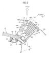
FIG. 2 ] An enlarged cross-sectional view taken along a line 2-2 inFIG. 1 . (Embodiment 1) - [
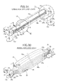
FIG. 3A ] A perspective view of an airbag in a non-deployed state. (Embodiment 1) - [
FIG. 3B ] A perspective view of the airbag in a deployed state. (Embodiment 1) - [
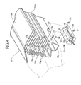
FIG. 4 ] An enlarged and exploded perspective view of a part indicated by an arrow 4 inFIG. 3A . (Embodiment 1) - [
FIG. 5 ] An enlarged perspective view of a part indicated by an arrow 5 inFIG. 3A . (Embodiment 1) - [
FIG. 6 ] A view corresponding toFIG. 2 and explaining an operation when the airbag deploys. (Embodiment 1) - [
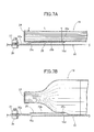
FIG. 7A ] A cross-sectional view taken along a line 7(A)-7(A) inFIG. 3A . (Embodiment 1) - [
FIG. 7B ] A cross-sectional view taken along a line 7(B)-7(B) inFIG. 3B . (Embodiment 1) - [
FIG. 8 ] A perspective view of a stay. (Embodiment 2) - [
FIG. 9 ] A view explaining an operation of a conventional example. (Conventional Example) - [
FIG. 10A ] A perspective view of an airbag in a non-deployed state. (Embodiment 3) - [
FIG. 10B ] A perspective view of the airbag in a deployed state. (Embodiment 3) - [
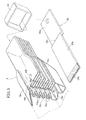
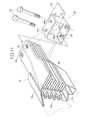
FIG. 11 ] An enlarged perspective view of a part indicated by anarrow 11 inFIG. 10A . (Embodiment 3) - [
FIG. 12A ] A cross-sectional view taken along a line 12(A)-12(A) inFIG. 10A . (Embodiment 3) - [
FIG. 12B ] A cross-sectional view taken along a line 12(B)-12(B) inFIG. 10B . (Embodiment 3) - [
FIG. 13 ] A cross-sectional view taken along a line 13-13 inFIG. 12A . (Embodiment 3) - [
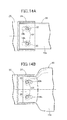
FIG. 14A ] A cross-sectional view taken along a line 14(A)-14(A) inFIG. 12A . (Embodiment 3) - [
FIG. 14B ] A cross-sectional view taken along a line 14(B)-14(B) inFIG. 12B . (Embodiment 3) - [
FIG. 15A ] A view corresponding to theFIG. 12A . (Embodiment 4) - [
FIG. 15B ] A view corresponding to theFIG. 12B . (Embodiment 4) -
- 15
- Front pillar
- 16d
- Attachment surface
- 18
- Airbag
- 18h
- Long hole
- 19
- Inflator
- 24
- End cap
- 25
- Stay
- 25a
- First fixation part
- 25b
- Second fixation part
- 25c
- Connecting part
- 25d
- Bent flange
- 34
- Bolt (shaft member)
- D
- Diameter
- L
- Distance
- α
- Space
- Embodiments of the present invention will be described below based on the attached drawings.
- A first embodiment of the present invention will be described below based on
FIGS. 1 to 7B . - As shown in
FIG. 1 , an automobile has afront windshield 12 in the rear of ahood 11, andfront pillars front pillars right edge portions front windshield 12 anddoor glasses front doors - As shown in
FIG. 2 , thefront pillar 15 is formed in a closed cross section by bonding together anouter panel 16 situated in an outer side of a vehicle body and an inner panel 17 situated in an inner side of the vehicle body. Anairbag 18 made of metal, which also serves as a pillar garnish, is folded and arranged in front of afront surface 16a of theouter panel 16. Thecorresponding edge portion 12a of thefront windshield 12 is adhered to front faces ofjoint sections outer panel 16 and the inner panel 17, respectively, with an adhesive 21 with adam rubber 20 being interposed in between. - The
airbag 18 obtained by folding a tube-shaped metal tube includes agarnish part 18a, a windshield-side foldedpart 18b, an outer panel-side foldedpart 18c and aninflator supporting part 18d. Thegarnish part 18a smoothly extends from aside surface 16b of theouter panel 16 of thefront pillar 15 toward thefront windshield 12, and functions as a pillar garnish arranged between theouter panel 16 and thefront windshield 12. - The windshield-side folded
part 18b and the outer panel-side foldedpart 18c are each folded in an accordion shape behind (in the rear of) thegarnish part 18a for the purpose of securing the expansion margin of theairbag 18 when it is deployed. At this point, a folded width W2 of the outer panel-side foldedpart 18c is set larger than a folded width W1 of the windshield-side foldedpart 18b. - As clearly observed in
FIGS. 3A, 3B ,5 ,7A and 7B , opposite end portions of theairbag 18 in a folded state are molded to be thinner by pressing, and endcaps airbag 18 are sealed hermetically. Note that the width of theairbag 18 in the folded state may be uniform throughout the entire length of theairbag 18. - Vicinities of the respective opposite end portions of the
airbag 18 are fixed to anattachment surface 16d of theouter panel 16 of thefront pillar 15 with a pair ofstays stay 25 is obtained by bending a strip-shaped metal plate in a crank shape, and includes: afirst fixation part 25a configured to be fixed to theattachment surface 16d of theouter panel 16 with astud bolt 26 and anut 27; asecond fixation part 25b configured to be welded to the windshield-side foldedpart 18b of theairbag 18 with aweld part 25e; and a connectingpart 25c configured to connect the first andsecond fixation parts part 25c arises at a location near an open end of theend cap 24, and thefirst fixation part 25a faces a side surface of theend cap 24. Thereby, the connectingpart 25c cancels out the thickness of theend cap 24. Accordingly, theairbag 18 can be compactly fixed to theattachment surface 16d so as to extend along theattachment surface 16d. - A distance L between the
weld part 25e, in which thesecond fixation part 25b of thestay 25 is welded to the windshield-side foldedpart 18b of theairbag 18, and the open end of theend cap 24 is set equal to or larger than a half of a diameter D (for instance, 100 mm) of theairbag 18 after being deployed. It is desirable that the distance L should be set equal to the diameter D. - As clear from
FIGS. 2 to 4 , an inflator 19 configured to produce a gas for deploying theairbag 18 is attached in a lower end portion of theinflator supporting part 18d which faces thegarnish part 18a with the windshield-side foldedpart 18b and the outer panel-side foldedpart 18c interposed therebetween. The inflator 19 having a cylindrical shape is fixed to an inner surface of anattachment bracket 28 having an U-shape cross section with twofastening devices attachment bracket 28 is overlaid anopening 18e formed in theinflator supporting part 18d of theairbag 18 from outside and fixed to theinflator supporting part 18d withbolts 30 ... and nuts 31 .... - As clear from
FIG. 2 , an outer panel-side lip 32 is arranged in a boundary between thegarnish part 18a and the outer panel-side foldedpart 18c of theairbag 18. This outer panel-side lip 32 is configured to be in contact with thefront surface 16a of theouter panel 16. A windshield-side lip 33 is installed in a boundary between the windshield-side foldedpart 18b and theinflator supporting part 18d of theairbag 18. This windshield-side lip 33 is configured to be in contact with a front surface of theedge portion 12a of thefront windshield 12. The outer panel-side lip 32 and the windshield-side lip 33 block rainwater and the like from entering theinflator supporting part 18d side of theairbag 18; therefore, the inflator 19 can be protected. - As clearly indicated in
FIGS. 2 and3B ,multiple vent holes 18f ... are formed in a vicinity of an end portion (for instance, an upper portion) of theairbag 18. The vent holes 18f ... are formed inflat parts 18g ... located in the accordion-folded part of the windshield-side foldedpart 18b and the outer panel-side foldedparts 18c. At the same time, the vent holes 18f ... are arranged in a way that novent holes flat parts vent holes - Next, descriptions will be provided for an operation of the embodiment of the present invention including the foregoing configuration.
- In a normal time when the
airbag 18 is not deployed, thegarnish part 18a of theairbag 18 smoothly extends toward theside surface 16b of theouter panel 16 of thefront pillar 15, and exhibits a pillar garnish function. Accordingly, this makes it possible to abolish a specialized pillar garnish, and thus to reduce parts in number. Furthermore, by replacing the conventional pillar garnish, theairbag 18 can be compactly installed between thefront pillar 15 and thefront windshield 12. Therefore, neither case nor cover is required for storing the foldedairbag 18, while a good external appearance around thefront pillar 15 is maintained. - Once it is detected that the vehicle has collided with a pedestrian, the
inflator 19 is actuated, and an internal pressure of theairbag 18 increases due to the gas produced by theinflator 19. Then, as shown inFIG. 6 , due to this increase in the internal pressure, the windshield-side foldedpart 18b and the outer panel-side foldedpart 18c of theairbag 18 which are folded in an accordion shape are first inflated toward the outside of the vehicle body, then deployed in the left and right directions in a way that thefront surface 16a and theside surface 16b of theouter panel 16 of thefront pillar 15 are covered. - At this time, as shown in
FIG. 7B , theairbag 18 is capable of freely inflating with the end caps 24, 24 being kept away from theouter panel 16 within a range of the distance L between theweld parts airbag 18 which are away from the open ends of the end caps 24, 24 by the distance L are welded to thestays weld parts airbag 18 can be deployed in such a stable shape that the diameter throughout the entire length of theairbag 18 is uniform. - As shown in
FIG. 9 , if the end caps 24, 24 of theairbag 18 are directly fixed to theouter panel 16 with thestays outer panel 16. Therefore, it results not only in making the inflation of each of the opposite end portions of theairbag 18 incomplete, but also in bending an intermediate part of theairbag 18 in a longitudinal direction thereof in a way of moving away from theouter panel 16. Accordingly, a portion of theairbag 18 located inward in the bending direction would be compressed and thus buckled. Hence, the deployed shape of theairbag 18 may be unstable. - Moreover, by including the windshield-side folded
part 18b and the outer panel-side foldedpart 18c, theairbag 18 securely makes the peripheral length thereof after being deployed longer, and thereby can cover a wider area of thefront pillar 15. Accordingly, a shock absorbing capability of theairbag 18 can be enhanced. In addition, thefront pillar 15 gives a larger impact on a pedestrian because thefront pillar 15 is harder than thefront windshield 12. However, by setting the folded width W2 of the outer panel-side foldedpart 18c larger than the folded width W1 of the windshield-side foldedpart 18b, an expansion margin (the amount of expansion) of the outer panel-side foldedpart 18c when theairbag 18 is deployed is increased, and theairbag 18 is deployed in a way that theairbag 18 is wrapped around theside surface 16b side of theouter panel 16. Thus, the shock absorbing capability of theairbag 18 can be further enhanced. - Furthermore, an airbag system for a pedestrian has a characteristic that time which lapses before the pedestrian collides with the
front pillar 15 tends to relatively vary largely depending on the physique of the pedestrian and the velocity at which the vehicle is running at the time of collision. For this reason, a problem with a conventional airbag made of cloth is that an inflator with a large volume, which is configured to produce the gas continuously, is required for the purpose of keeping the airbag deployed for a predetermined length of time. On the contrary, the present embodiment employs theairbag 18 made of metal. Once deployed, theairbag 18 is capable of keeping the deployed state even after the supply of the gas is ended. This plastic deformation allows theairbag 18 to absorb the shock of the collision with a pedestrian. For this reason, theairbag 18 exhibits its shock absorbing capability effectively no matter what timing a pedestrian may collides with thefront pillar 15 even with the inflator 19 having a smaller volume. - Furthermore, the vent holes 18f are formed in the
flat parts 18g of the windshield-side foldedpart 18b and the outer panel-side foldedpart 18c of theairbag 18 which are in an accordion shape; and the positions where the vent holes 18f are formed are located in the vicinity of one end portion of theairbag 18 in a longitudinal direction thereof. Therefore, each two neighboringflat parts 18g are almost in close contact with each other in an initial stage of the deploying of theairbag 18. Thus, the vent holes 18f of theairbag 18 are closed by the correspondingflat parts 18g. This makes it possible to quickly deploy theairbag 18 while preventing unnecessary leakage of the gas from thevent holes 18f. Then, in the terminal stage of the deploying of theairbag 18, neighboringflat parts 18g move away from each other, and the vent holes 18f are opened. Accordingly, an excessive increase in the internal pressure can be prevented by discharging an excessive amount of gas from thevent holes 18f. - Next, descriptions will be provided for a second embodiment of the present invention based on
FIG. 8 . - In the second embodiment,
bent flanges stay 25. Thesebent flanges stay 25; thus preventing deformation at the time of deploying theairbag 18; and making the deployed shape of theairbag 18 more stable. - Next, descriptions will be provided for a third embodiment of the present invention based on
FIGS. 10 to 14B . - As clear from
FIGS. 10A, 10B ,11 and12A to 14B , opposite end portions of anairbag 18 in a folded state are molded to be thinner by pressing, and are fitted into openings of boxed-shaped end caps 24, 24, respectively, to be fixed thereto. In this way, since the end caps 24, 24 are made into the shape of a box having an opening into which the folded end portion of theairbag 18 is inserted, the end portions of theairbag 18 can be easily and securely fixed to the end caps 24, 24. Note that the foldedairbag 18 may have a uniform width over the entire length thereof. - Paired stays 25, 25 unitarily formed with the end caps 24, 24 are fixed to an
attachment surface 16d of anouter panel 16 of afront pillar 15. Eachstay 25 is one obtained by bending a strip-shaped metal plate into a crank shape. Thestay 25 is fixed to theattachment surface 16d of theouter panel 16 with astud bolt 26 and anut 27. - Two
long holes airbag 18 penetrate the respective end portions of theairbag 18.Bolts bolt holes 24a ... of the end caps 24 and thelong holes airbag 18 are respectively screwed to weld nuts 35, 35 provided to thestay 25. While theairbag 18 is not deployed as shown inFIGS. 12A and14A , thebolts long holes airbag 18. While theairbag 18 is deployed as shown inFIGS. 12B and14B , thelong holes bolts bolts long holes airbag 18. - Next, descriptions will be provided for an operation of the third embodiment of the present invention including the foregoing configuration.
- Once the
airbag 18 is deployed, the airbag changes its shape in such a way that theairbag 18 contracts in the longitudinal direction in accordance with an increase in the diameter thereof. As a result, tension occurs within the metal plate of theairbag 18 in the longitudinal direction. For the purpose of obtaining an excellent shock absorbing performance through the entire length of theairbag 18, it is desirable that the opposite end portions of theairbag 18 should have an increasing diameter starting immediately from the parts thereof fixed to the end caps 24, 24. However, there is a problem that the opposite end portions of theairbag 18 are hard to be deployed due to the occurrence of the above-described tension. - In the present embodiment, however, once the tension occurs in the longitudinal direction with the deployment of the
airbag 18, thelong holes respective bolts airbag 18 as shown inFIGS. 12A, 12B ,14A and 14B . Accordingly, the opposite end portions of theairbag 18 move inward in the longitudinal direction, inhibiting the occurrence of the tension. Consequently, the opposite end portions of theairbag 18 can be deployed securely; therefore, theairbag 18 can exert the excellent shock absorbing performance through the entire length thereof. - Moreover, while the
airbag 18 is being deployed, gaps are formed between thebolts long holes airbag 18, no special vent holes need to be formed in the metal plate of theairbag 18, resulting in a reduction in the processing costs. Alternatively, when vent holes are to be formed in theairbag 18, the number of the vent holes can be reduced. - Next, descriptions will be provided for a fourth embodiment of the present invention based on
FIGS. 15A and 15B . - The fourth embodiment is an airbag system in which a space α is formed between a front surface of a folded
airbag 18 and afront surface 24c of eachend cap 24 by making the dimensions of eachend cap 24 in the front-back directions larger and supporting a back surface of the foldedairbag 18 by arbitrary means at a location in which the back surface of the foldedairbag 18 is in contact with aback surface 24b of eachend cap 24. - When the
airbag 18 is deployed, not only thelong holes respective bolts airbag 18 but also the opposite end portions of theairbag 18 slides frontward along therespective bolts airbag 18 to be deployed more securely; thus, theairbag 18 can exert excellent shock absorbing performance. - The embodiments of the present invention have been described above. However, various design changes can be made on the present invention within the scope not departing from the gist of the present invention.
- For instance, the way of folding the
airbag 18 is not limited to the embodiments, and any appropriate way of folding theairbag 18 can be adopted.
Claims (11)
- An airbag system comprising an airbag (18) obtained by closing each of opposite end portions of a folded metal tube with an end cap (24) and attached to an attachment surface (16d) of a front pillar (15), the airbag system protecting a pedestrian by deploying the airbag (18) along the front pillar (15) with a gas produced by an inflator (19), wherein
the airbag (18) is attached to the attachment surface (16d) by connecting a portion of the airbag (18) to the attachment surface (16d) with a stay (25) interposed therebetween, said portion being located away from the end cap (24) towards an intermediate part of the airbag (18) by a predetermined distance (L) in a longitudinal direction of the airbag (18), the attachment surface (16d) located outside the end cap (24) in the longitudinal direction of the airbag (18). - The airbag system according to claim 1, wherein the predetermined distance (L) is not less than a half of a diameter (D) of the airbag (18) after being deployed.
- The airbag system according to claim 2, wherein the predetermined distance (L) is substantially equal to the diameter (D) of the airbag (18) after being deployed.
- The airbag system according to any one of claims 1 to 3, wherein
the stay (25) is formed in a crank shape and includes: a first fixation part (25a) fixed to the attachment surface (16d); a second fixation part (25b) fixed to the airbag (18); and a connecting part (25c) connecting the first and second fixation parts (25a, 25b) together, and
the end cap (24) is opposed to the first fixation part (25a). - The airbag system according to claim 4, wherein the stay (25) is formed by a strip-shaped metal plate, and bent flanges (25d) are formed respectively along opposite side edges of the stay (25).
- The airbag system according to claim 1, wherein opposite end portions of the airbag (18) and the respective end caps (24) are connected movably relative to each other when the airbag (18) is deployed.
- The airbag system according to claim 6, wherein
long holes (18h) are formed in the opposite end portions of the airbag (18), each long hole (18h) extending in the longitudinal direction of the airbag (18), and
shaft members (34) fixed to the end caps (24) penetrate the respective long holes (18h). - The airbag system according to claim 7, wherein
a space (α) extending along each of the shaft members (34) is formed between an outer surface of the airbag (18) in a folded state and an inner surface of the corresponding end cap (24), and
each of the opposite end portions of the airbag (18) is deployed to make the space (α) disappear. - The airbag system according to any one of claims 6 to 8, wherein,
in the airbag (18) in a folded state,
a surface facing in a front-and-rear direction of a vehicle body is flat; and
a surface facing in a left-and-right direction of the vehicle body is folded in an accordion shape. - The airbag system according to any one of claims 6 to 9, wherein the end caps (24) are each formed of a box shape having an opening to which the corresponding end portion of the airbag (18) in a folded state is inserted.
- The airbag system according to claim 8, wherein a gap (α) between the shaft member (34) and the long hole (18h) functions as a vent hole of the airbag (18).
Applications Claiming Priority (3)
| Application Number | Priority Date | Filing Date | Title |
|---|---|---|---|
| US12/789,700 US8365857B2 (en) | 2010-05-28 | 2010-05-28 | Airbag system |
| US12/831,671 US7988183B1 (en) | 2010-07-07 | 2010-07-07 | Airbag system |
| PCT/JP2011/062128 WO2011149027A1 (en) | 2010-05-28 | 2011-05-26 | Airbag device |
Publications (3)
| Publication Number | Publication Date |
|---|---|
| EP2578455A1 true EP2578455A1 (en) | 2013-04-10 |
| EP2578455A4 EP2578455A4 (en) | 2013-11-27 |
| EP2578455B1 EP2578455B1 (en) | 2014-08-20 |
Family
ID=45004012
Family Applications (1)
| Application Number | Title | Priority Date | Filing Date |
|---|---|---|---|
| EP11786726.7A Not-in-force EP2578455B1 (en) | 2010-05-28 | 2011-05-26 | Airbag system |
Country Status (4)
| Country | Link |
|---|---|
| EP (1) | EP2578455B1 (en) |
| JP (1) | JPWO2011149027A1 (en) |
| CN (1) | CN102917922A (en) |
| WO (1) | WO2011149027A1 (en) |
Cited By (1)
| Publication number | Priority date | Publication date | Assignee | Title |
|---|---|---|---|---|
| DE102024129839A1 (en) | 2024-10-15 | 2026-04-16 | Dr. Ing. H.C. F. Porsche Aktiengesellschaft | System and procedure for the protection of pedestrians in a frontal collision with a vehicle |
Families Citing this family (2)
| Publication number | Priority date | Publication date | Assignee | Title |
|---|---|---|---|---|
| KR102576838B1 (en) * | 2021-08-12 | 2023-09-11 | 국방과학연구소 | Air-bag apparatus for a guided weapon and the guided weapon |
| KR102639435B1 (en) * | 2021-08-18 | 2024-02-22 | 국방과학연구소 | Air-bag apparatus for a guided object and the guided weapon |
Family Cites Families (8)
| Publication number | Priority date | Publication date | Assignee | Title |
|---|---|---|---|---|
| JP2002283939A (en) * | 2001-03-29 | 2002-10-03 | Toyota Motor Corp | Pedestrian protection airbag device |
| GB2397559A (en) * | 2003-01-22 | 2004-07-28 | Autoliv Dev | Airbag arrangement for windscreen and A-pillar |
| JP2005096686A (en) * | 2003-09-26 | 2005-04-14 | Toyota Motor Corp | Pillar airbag device |
| JP2006282105A (en) * | 2005-04-04 | 2006-10-19 | Toyota Motor Corp | Shock absorption structure for vehicles |
| JP5342213B2 (en) * | 2007-11-20 | 2013-11-13 | 本田技研工業株式会社 | Air bag device for pedestrian protection |
| JP5030809B2 (en) * | 2008-02-07 | 2012-09-19 | タカタ株式会社 | Airbag device |
| JP4895397B2 (en) | 2008-03-13 | 2012-03-14 | 富士フイルム株式会社 | Wiring board manufacturing method and wiring board manufacturing apparatus |
| EP2465735B1 (en) * | 2009-09-29 | 2014-05-07 | Honda Motor Co., Ltd. | Airbag device |
-
2011
- 2011-05-26 CN CN2011800266438A patent/CN102917922A/en active Pending
- 2011-05-26 JP JP2012517316A patent/JPWO2011149027A1/en not_active Withdrawn
- 2011-05-26 WO PCT/JP2011/062128 patent/WO2011149027A1/en not_active Ceased
- 2011-05-26 EP EP11786726.7A patent/EP2578455B1/en not_active Not-in-force
Cited By (1)
| Publication number | Priority date | Publication date | Assignee | Title |
|---|---|---|---|---|
| DE102024129839A1 (en) | 2024-10-15 | 2026-04-16 | Dr. Ing. H.C. F. Porsche Aktiengesellschaft | System and procedure for the protection of pedestrians in a frontal collision with a vehicle |
Also Published As
| Publication number | Publication date |
|---|---|
| JPWO2011149027A1 (en) | 2013-07-25 |
| CN102917922A (en) | 2013-02-06 |
| EP2578455A4 (en) | 2013-11-27 |
| EP2578455B1 (en) | 2014-08-20 |
| WO2011149027A1 (en) | 2011-12-01 |
Similar Documents
| Publication | Publication Date | Title |
|---|---|---|
| US8186472B2 (en) | Pedestrian protection airbag device | |
| US7669884B2 (en) | Air bag device | |
| US7988183B1 (en) | Airbag system | |
| CN105829171B (en) | Pedestrian protection airbag device for vehicle | |
| US20170182967A1 (en) | Airbag device | |
| US8585080B2 (en) | Airbag arrangement | |
| JP6269524B2 (en) | Pedestrian protection airbag device | |
| EP1700758A1 (en) | Airbag and airbag device for protecting a pedestrian or the like | |
| US8365857B2 (en) | Airbag system | |
| EP2578455B1 (en) | Airbag system | |
| EP2465735B1 (en) | Airbag device | |
| JP2007112183A (en) | Airbag device for car exterior | |
| JP5437158B2 (en) | Airbag device | |
| EP2570308A1 (en) | Air-bag device | |
| JP4441444B2 (en) | Collision protection device | |
| JP2009184431A (en) | Vehicle occupant protection device | |
| JP5437159B2 (en) | Airbag device | |
| JP3702786B2 (en) | Airbag device for vehicle | |
| JP2006327340A (en) | Crew protection device | |
| JP4089723B2 (en) | Hood airbag device for vehicle | |
| JP2002293212A (en) | Arrangement structure of head protection airbag for sliding door vehicle | |
| JP5450244B2 (en) | Airbag device | |
| JPH07237522A (en) | Installation structure of airbag device | |
| JP2011235813A5 (en) | ||
| JP2011235829A5 (en) |
Legal Events
| Date | Code | Title | Description |
|---|---|---|---|
| PUAI | Public reference made under article 153(3) epc to a published international application that has entered the european phase |
Free format text: ORIGINAL CODE: 0009012 |
|
| 17P | Request for examination filed |
Effective date: 20121114 |
|
| AK | Designated contracting states |
Kind code of ref document: A1 Designated state(s): AL AT BE BG CH CY CZ DE DK EE ES FI FR GB GR HR HU IE IS IT LI LT LU LV MC MK MT NL NO PL PT RO RS SE SI SK SM TR |
|
| RIN1 | Information on inventor provided before grant (corrected) |
Inventor name: NELSON EARL Inventor name: PIPKORN BENGT Inventor name: DRAKE ERIC Inventor name: OKAMOTO YUTAKA |
|
| DAX | Request for extension of the european patent (deleted) | ||
| A4 | Supplementary search report drawn up and despatched |
Effective date: 20131030 |
|
| RIC1 | Information provided on ipc code assigned before grant |
Ipc: B60R 21/36 20110101AFI20131024BHEP |
|
| 17Q | First examination report despatched |
Effective date: 20131111 |
|
| GRAP | Despatch of communication of intention to grant a patent |
Free format text: ORIGINAL CODE: EPIDOSNIGR1 |
|
| INTG | Intention to grant announced |
Effective date: 20140416 |
|
| GRAS | Grant fee paid |
Free format text: ORIGINAL CODE: EPIDOSNIGR3 |
|
| GRAA | (expected) grant |
Free format text: ORIGINAL CODE: 0009210 |
|
| AK | Designated contracting states |
Kind code of ref document: B1 Designated state(s): AL AT BE BG CH CY CZ DE DK EE ES FI FR GB GR HR HU IE IS IT LI LT LU LV MC MK MT NL NO PL PT RO RS SE SI SK SM TR |
|
| REG | Reference to a national code |
Ref country code: GB Ref legal event code: FG4D |
|
| REG | Reference to a national code |
Ref country code: CH Ref legal event code: EP |
|
| REG | Reference to a national code |
Ref country code: AT Ref legal event code: REF Ref document number: 683260 Country of ref document: AT Kind code of ref document: T Effective date: 20140915 |
|
| REG | Reference to a national code |
Ref country code: IE Ref legal event code: FG4D |
|
| REG | Reference to a national code |
Ref country code: DE Ref legal event code: R096 Ref document number: 602011009359 Country of ref document: DE Effective date: 20141002 |
|
| REG | Reference to a national code |
Ref country code: AT Ref legal event code: MK05 Ref document number: 683260 Country of ref document: AT Kind code of ref document: T Effective date: 20140820 |
|
| REG | Reference to a national code |
Ref country code: LT Ref legal event code: MG4D |
|
| PG25 | Lapsed in a contracting state [announced via postgrant information from national office to epo] |
Ref country code: PT Free format text: LAPSE BECAUSE OF FAILURE TO SUBMIT A TRANSLATION OF THE DESCRIPTION OR TO PAY THE FEE WITHIN THE PRESCRIBED TIME-LIMIT Effective date: 20141222 Ref country code: SE Free format text: LAPSE BECAUSE OF FAILURE TO SUBMIT A TRANSLATION OF THE DESCRIPTION OR TO PAY THE FEE WITHIN THE PRESCRIBED TIME-LIMIT Effective date: 20140820 Ref country code: GR Free format text: LAPSE BECAUSE OF FAILURE TO SUBMIT A TRANSLATION OF THE DESCRIPTION OR TO PAY THE FEE WITHIN THE PRESCRIBED TIME-LIMIT Effective date: 20141121 Ref country code: NO Free format text: LAPSE BECAUSE OF FAILURE TO SUBMIT A TRANSLATION OF THE DESCRIPTION OR TO PAY THE FEE WITHIN THE PRESCRIBED TIME-LIMIT Effective date: 20141120 Ref country code: ES Free format text: LAPSE BECAUSE OF FAILURE TO SUBMIT A TRANSLATION OF THE DESCRIPTION OR TO PAY THE FEE WITHIN THE PRESCRIBED TIME-LIMIT Effective date: 20140820 Ref country code: BG Free format text: LAPSE BECAUSE OF FAILURE TO SUBMIT A TRANSLATION OF THE DESCRIPTION OR TO PAY THE FEE WITHIN THE PRESCRIBED TIME-LIMIT Effective date: 20141120 Ref country code: LT Free format text: LAPSE BECAUSE OF FAILURE TO SUBMIT A TRANSLATION OF THE DESCRIPTION OR TO PAY THE FEE WITHIN THE PRESCRIBED TIME-LIMIT Effective date: 20140820 Ref country code: FI Free format text: LAPSE BECAUSE OF FAILURE TO SUBMIT A TRANSLATION OF THE DESCRIPTION OR TO PAY THE FEE WITHIN THE PRESCRIBED TIME-LIMIT Effective date: 20140820 |
|
| PG25 | Lapsed in a contracting state [announced via postgrant information from national office to epo] |
Ref country code: AT Free format text: LAPSE BECAUSE OF FAILURE TO SUBMIT A TRANSLATION OF THE DESCRIPTION OR TO PAY THE FEE WITHIN THE PRESCRIBED TIME-LIMIT Effective date: 20140820 Ref country code: LV Free format text: LAPSE BECAUSE OF FAILURE TO SUBMIT A TRANSLATION OF THE DESCRIPTION OR TO PAY THE FEE WITHIN THE PRESCRIBED TIME-LIMIT Effective date: 20140820 Ref country code: IS Free format text: LAPSE BECAUSE OF FAILURE TO SUBMIT A TRANSLATION OF THE DESCRIPTION OR TO PAY THE FEE WITHIN THE PRESCRIBED TIME-LIMIT Effective date: 20141220 Ref country code: RS Free format text: LAPSE BECAUSE OF FAILURE TO SUBMIT A TRANSLATION OF THE DESCRIPTION OR TO PAY THE FEE WITHIN THE PRESCRIBED TIME-LIMIT Effective date: 20140820 Ref country code: HR Free format text: LAPSE BECAUSE OF FAILURE TO SUBMIT A TRANSLATION OF THE DESCRIPTION OR TO PAY THE FEE WITHIN THE PRESCRIBED TIME-LIMIT Effective date: 20140820 |
|
| PG25 | Lapsed in a contracting state [announced via postgrant information from national office to epo] |
Ref country code: NL Free format text: LAPSE BECAUSE OF FAILURE TO SUBMIT A TRANSLATION OF THE DESCRIPTION OR TO PAY THE FEE WITHIN THE PRESCRIBED TIME-LIMIT Effective date: 20140820 |
|
| PG25 | Lapsed in a contracting state [announced via postgrant information from national office to epo] |
Ref country code: IT Free format text: LAPSE BECAUSE OF FAILURE TO SUBMIT A TRANSLATION OF THE DESCRIPTION OR TO PAY THE FEE WITHIN THE PRESCRIBED TIME-LIMIT Effective date: 20140820 Ref country code: EE Free format text: LAPSE BECAUSE OF FAILURE TO SUBMIT A TRANSLATION OF THE DESCRIPTION OR TO PAY THE FEE WITHIN THE PRESCRIBED TIME-LIMIT Effective date: 20140820 Ref country code: SK Free format text: LAPSE BECAUSE OF FAILURE TO SUBMIT A TRANSLATION OF THE DESCRIPTION OR TO PAY THE FEE WITHIN THE PRESCRIBED TIME-LIMIT Effective date: 20140820 Ref country code: CZ Free format text: LAPSE BECAUSE OF FAILURE TO SUBMIT A TRANSLATION OF THE DESCRIPTION OR TO PAY THE FEE WITHIN THE PRESCRIBED TIME-LIMIT Effective date: 20140820 Ref country code: DK Free format text: LAPSE BECAUSE OF FAILURE TO SUBMIT A TRANSLATION OF THE DESCRIPTION OR TO PAY THE FEE WITHIN THE PRESCRIBED TIME-LIMIT Effective date: 20140820 Ref country code: RO Free format text: LAPSE BECAUSE OF FAILURE TO SUBMIT A TRANSLATION OF THE DESCRIPTION OR TO PAY THE FEE WITHIN THE PRESCRIBED TIME-LIMIT Effective date: 20140820 |
|
| REG | Reference to a national code |
Ref country code: FR Ref legal event code: PLFP Year of fee payment: 5 Ref country code: DE Ref legal event code: R097 Ref document number: 602011009359 Country of ref document: DE |
|
| PG25 | Lapsed in a contracting state [announced via postgrant information from national office to epo] |
Ref country code: PL Free format text: LAPSE BECAUSE OF FAILURE TO SUBMIT A TRANSLATION OF THE DESCRIPTION OR TO PAY THE FEE WITHIN THE PRESCRIBED TIME-LIMIT Effective date: 20140820 |
|
| PLBE | No opposition filed within time limit |
Free format text: ORIGINAL CODE: 0009261 |
|
| STAA | Information on the status of an ep patent application or granted ep patent |
Free format text: STATUS: NO OPPOSITION FILED WITHIN TIME LIMIT |
|
| 26N | No opposition filed |
Effective date: 20150521 |
|
| PGFP | Annual fee paid to national office [announced via postgrant information from national office to epo] |
Ref country code: DE Payment date: 20150415 Year of fee payment: 5 Ref country code: GB Payment date: 20150521 Year of fee payment: 5 |
|
| PGFP | Annual fee paid to national office [announced via postgrant information from national office to epo] |
Ref country code: FR Payment date: 20150521 Year of fee payment: 5 |
|
| PG25 | Lapsed in a contracting state [announced via postgrant information from national office to epo] |
Ref country code: SI Free format text: LAPSE BECAUSE OF FAILURE TO SUBMIT A TRANSLATION OF THE DESCRIPTION OR TO PAY THE FEE WITHIN THE PRESCRIBED TIME-LIMIT Effective date: 20140820 |
|
| REG | Reference to a national code |
Ref country code: CH Ref legal event code: PL |
|
| PG25 | Lapsed in a contracting state [announced via postgrant information from national office to epo] |
Ref country code: CH Free format text: LAPSE BECAUSE OF NON-PAYMENT OF DUE FEES Effective date: 20150531 Ref country code: MC Free format text: LAPSE BECAUSE OF FAILURE TO SUBMIT A TRANSLATION OF THE DESCRIPTION OR TO PAY THE FEE WITHIN THE PRESCRIBED TIME-LIMIT Effective date: 20140820 Ref country code: LU Free format text: LAPSE BECAUSE OF FAILURE TO SUBMIT A TRANSLATION OF THE DESCRIPTION OR TO PAY THE FEE WITHIN THE PRESCRIBED TIME-LIMIT Effective date: 20150526 Ref country code: LI Free format text: LAPSE BECAUSE OF NON-PAYMENT OF DUE FEES Effective date: 20150531 |
|
| REG | Reference to a national code |
Ref country code: IE Ref legal event code: MM4A |
|
| PG25 | Lapsed in a contracting state [announced via postgrant information from national office to epo] |
Ref country code: IE Free format text: LAPSE BECAUSE OF NON-PAYMENT OF DUE FEES Effective date: 20150526 |
|
| PG25 | Lapsed in a contracting state [announced via postgrant information from national office to epo] |
Ref country code: BE Free format text: LAPSE BECAUSE OF FAILURE TO SUBMIT A TRANSLATION OF THE DESCRIPTION OR TO PAY THE FEE WITHIN THE PRESCRIBED TIME-LIMIT Effective date: 20140820 |
|
| REG | Reference to a national code |
Ref country code: DE Ref legal event code: R119 Ref document number: 602011009359 Country of ref document: DE |
|
| PG25 | Lapsed in a contracting state [announced via postgrant information from national office to epo] |
Ref country code: MT Free format text: LAPSE BECAUSE OF FAILURE TO SUBMIT A TRANSLATION OF THE DESCRIPTION OR TO PAY THE FEE WITHIN THE PRESCRIBED TIME-LIMIT Effective date: 20140820 |
|
| GBPC | Gb: european patent ceased through non-payment of renewal fee |
Effective date: 20160526 |
|
| REG | Reference to a national code |
Ref country code: FR Ref legal event code: ST Effective date: 20170131 |
|
| PG25 | Lapsed in a contracting state [announced via postgrant information from national office to epo] |
Ref country code: DE Free format text: LAPSE BECAUSE OF NON-PAYMENT OF DUE FEES Effective date: 20161201 Ref country code: FR Free format text: LAPSE BECAUSE OF NON-PAYMENT OF DUE FEES Effective date: 20160531 |
|
| PG25 | Lapsed in a contracting state [announced via postgrant information from national office to epo] |
Ref country code: GB Free format text: LAPSE BECAUSE OF NON-PAYMENT OF DUE FEES Effective date: 20160526 Ref country code: HU Free format text: LAPSE BECAUSE OF FAILURE TO SUBMIT A TRANSLATION OF THE DESCRIPTION OR TO PAY THE FEE WITHIN THE PRESCRIBED TIME-LIMIT; INVALID AB INITIO Effective date: 20110526 Ref country code: SM Free format text: LAPSE BECAUSE OF FAILURE TO SUBMIT A TRANSLATION OF THE DESCRIPTION OR TO PAY THE FEE WITHIN THE PRESCRIBED TIME-LIMIT Effective date: 20140820 |
|
| PG25 | Lapsed in a contracting state [announced via postgrant information from national office to epo] |
Ref country code: CY Free format text: LAPSE BECAUSE OF FAILURE TO SUBMIT A TRANSLATION OF THE DESCRIPTION OR TO PAY THE FEE WITHIN THE PRESCRIBED TIME-LIMIT Effective date: 20140820 |
|
| PG25 | Lapsed in a contracting state [announced via postgrant information from national office to epo] |
Ref country code: TR Free format text: LAPSE BECAUSE OF FAILURE TO SUBMIT A TRANSLATION OF THE DESCRIPTION OR TO PAY THE FEE WITHIN THE PRESCRIBED TIME-LIMIT Effective date: 20140820 |
|
| PG25 | Lapsed in a contracting state [announced via postgrant information from national office to epo] |
Ref country code: MK Free format text: LAPSE BECAUSE OF FAILURE TO SUBMIT A TRANSLATION OF THE DESCRIPTION OR TO PAY THE FEE WITHIN THE PRESCRIBED TIME-LIMIT Effective date: 20140820 |
|
| PG25 | Lapsed in a contracting state [announced via postgrant information from national office to epo] |
Ref country code: AL Free format text: LAPSE BECAUSE OF FAILURE TO SUBMIT A TRANSLATION OF THE DESCRIPTION OR TO PAY THE FEE WITHIN THE PRESCRIBED TIME-LIMIT Effective date: 20140820 |