EP2576995B1 - Boite d'engrenages dans une turbomachine - Google Patents
Boite d'engrenages dans une turbomachine Download PDFInfo
- Publication number
- EP2576995B1 EP2576995B1 EP11727220.3A EP11727220A EP2576995B1 EP 2576995 B1 EP2576995 B1 EP 2576995B1 EP 11727220 A EP11727220 A EP 11727220A EP 2576995 B1 EP2576995 B1 EP 2576995B1
- Authority
- EP
- European Patent Office
- Prior art keywords
- gearbox
- bearing
- transmission shaft
- gearbox according
- shaft
- Prior art date
- Legal status (The legal status is an assumption and is not a legal conclusion. Google has not performed a legal analysis and makes no representation as to the accuracy of the status listed.)
- Active
Links
Images

Classifications
-
- F—MECHANICAL ENGINEERING; LIGHTING; HEATING; WEAPONS; BLASTING
- F16—ENGINEERING ELEMENTS AND UNITS; GENERAL MEASURES FOR PRODUCING AND MAINTAINING EFFECTIVE FUNCTIONING OF MACHINES OR INSTALLATIONS; THERMAL INSULATION IN GENERAL
- F16H—GEARING
- F16H1/00—Toothed gearings for conveying rotary motion
- F16H1/02—Toothed gearings for conveying rotary motion without gears having orbital motion
- F16H1/04—Toothed gearings for conveying rotary motion without gears having orbital motion involving only two intermeshing members
-
- F—MECHANICAL ENGINEERING; LIGHTING; HEATING; WEAPONS; BLASTING
- F01—MACHINES OR ENGINES IN GENERAL; ENGINE PLANTS IN GENERAL; STEAM ENGINES
- F01D—NON-POSITIVE DISPLACEMENT MACHINES OR ENGINES, e.g. STEAM TURBINES
- F01D15/00—Adaptations of machines or engines for special use; Combinations of engines with devices driven thereby
- F01D15/08—Adaptations for driving, or combinations with, pumps
-
- F—MECHANICAL ENGINEERING; LIGHTING; HEATING; WEAPONS; BLASTING
- F01—MACHINES OR ENGINES IN GENERAL; ENGINE PLANTS IN GENERAL; STEAM ENGINES
- F01D—NON-POSITIVE DISPLACEMENT MACHINES OR ENGINES, e.g. STEAM TURBINES
- F01D15/00—Adaptations of machines or engines for special use; Combinations of engines with devices driven thereby
- F01D15/10—Adaptations for driving, or combinations with, electric generators
-
- F—MECHANICAL ENGINEERING; LIGHTING; HEATING; WEAPONS; BLASTING
- F01—MACHINES OR ENGINES IN GENERAL; ENGINE PLANTS IN GENERAL; STEAM ENGINES
- F01D—NON-POSITIVE DISPLACEMENT MACHINES OR ENGINES, e.g. STEAM TURBINES
- F01D15/00—Adaptations of machines or engines for special use; Combinations of engines with devices driven thereby
- F01D15/12—Combinations with mechanical gearing
-
- F—MECHANICAL ENGINEERING; LIGHTING; HEATING; WEAPONS; BLASTING
- F01—MACHINES OR ENGINES IN GENERAL; ENGINE PLANTS IN GENERAL; STEAM ENGINES
- F01D—NON-POSITIVE DISPLACEMENT MACHINES OR ENGINES, e.g. STEAM TURBINES
- F01D25/00—Component parts, details, or accessories, not provided for in, or of interest apart from, other groups
- F01D25/16—Arrangement of bearings; Supporting or mounting bearings in casings
-
- F—MECHANICAL ENGINEERING; LIGHTING; HEATING; WEAPONS; BLASTING
- F01—MACHINES OR ENGINES IN GENERAL; ENGINE PLANTS IN GENERAL; STEAM ENGINES
- F01D—NON-POSITIVE DISPLACEMENT MACHINES OR ENGINES, e.g. STEAM TURBINES
- F01D25/00—Component parts, details, or accessories, not provided for in, or of interest apart from, other groups
- F01D25/16—Arrangement of bearings; Supporting or mounting bearings in casings
- F01D25/166—Sliding contact bearing
-
- F—MECHANICAL ENGINEERING; LIGHTING; HEATING; WEAPONS; BLASTING
- F02—COMBUSTION ENGINES; HOT-GAS OR COMBUSTION-PRODUCT ENGINE PLANTS
- F02C—GAS-TURBINE PLANTS; AIR INTAKES FOR JET-PROPULSION PLANTS; CONTROLLING FUEL SUPPLY IN AIR-BREATHING JET-PROPULSION PLANTS
- F02C7/00—Features, components parts, details or accessories, not provided for in, or of interest apart form groups F02C1/00 - F02C6/00; Air intakes for jet-propulsion plants
- F02C7/32—Arrangement, mounting, or driving, of auxiliaries
-
- F—MECHANICAL ENGINEERING; LIGHTING; HEATING; WEAPONS; BLASTING
- F16—ENGINEERING ELEMENTS AND UNITS; GENERAL MEASURES FOR PRODUCING AND MAINTAINING EFFECTIVE FUNCTIONING OF MACHINES OR INSTALLATIONS; THERMAL INSULATION IN GENERAL
- F16C—SHAFTS; FLEXIBLE SHAFTS; ELEMENTS OR CRANKSHAFT MECHANISMS; ROTARY BODIES OTHER THAN GEARING ELEMENTS; BEARINGS
- F16C19/00—Bearings with rolling contact, for exclusively rotary movement
- F16C19/54—Systems consisting of a plurality of bearings with rolling friction
-
- F—MECHANICAL ENGINEERING; LIGHTING; HEATING; WEAPONS; BLASTING
- F16—ENGINEERING ELEMENTS AND UNITS; GENERAL MEASURES FOR PRODUCING AND MAINTAINING EFFECTIVE FUNCTIONING OF MACHINES OR INSTALLATIONS; THERMAL INSULATION IN GENERAL
- F16C—SHAFTS; FLEXIBLE SHAFTS; ELEMENTS OR CRANKSHAFT MECHANISMS; ROTARY BODIES OTHER THAN GEARING ELEMENTS; BEARINGS
- F16C21/00—Combinations of sliding-contact bearings with ball or roller bearings, for exclusively rotary movement
-
- F—MECHANICAL ENGINEERING; LIGHTING; HEATING; WEAPONS; BLASTING
- F05—INDEXING SCHEMES RELATING TO ENGINES OR PUMPS IN VARIOUS SUBCLASSES OF CLASSES F01-F04
- F05D—INDEXING SCHEME FOR ASPECTS RELATING TO NON-POSITIVE-DISPLACEMENT MACHINES OR ENGINES, GAS-TURBINES OR JET-PROPULSION PLANTS
- F05D2220/00—Application
- F05D2220/70—Application in combination with
- F05D2220/76—Application in combination with an electrical generator
-
- F—MECHANICAL ENGINEERING; LIGHTING; HEATING; WEAPONS; BLASTING
- F05—INDEXING SCHEMES RELATING TO ENGINES OR PUMPS IN VARIOUS SUBCLASSES OF CLASSES F01-F04
- F05D—INDEXING SCHEME FOR ASPECTS RELATING TO NON-POSITIVE-DISPLACEMENT MACHINES OR ENGINES, GAS-TURBINES OR JET-PROPULSION PLANTS
- F05D2240/00—Components
- F05D2240/50—Bearings
- F05D2240/52—Axial thrust bearings
-
- F—MECHANICAL ENGINEERING; LIGHTING; HEATING; WEAPONS; BLASTING
- F05—INDEXING SCHEMES RELATING TO ENGINES OR PUMPS IN VARIOUS SUBCLASSES OF CLASSES F01-F04
- F05D—INDEXING SCHEME FOR ASPECTS RELATING TO NON-POSITIVE-DISPLACEMENT MACHINES OR ENGINES, GAS-TURBINES OR JET-PROPULSION PLANTS
- F05D2240/00—Components
- F05D2240/50—Bearings
- F05D2240/53—Hydrodynamic or hydrostatic bearings
-
- F—MECHANICAL ENGINEERING; LIGHTING; HEATING; WEAPONS; BLASTING
- F05—INDEXING SCHEMES RELATING TO ENGINES OR PUMPS IN VARIOUS SUBCLASSES OF CLASSES F01-F04
- F05D—INDEXING SCHEME FOR ASPECTS RELATING TO NON-POSITIVE-DISPLACEMENT MACHINES OR ENGINES, GAS-TURBINES OR JET-PROPULSION PLANTS
- F05D2250/00—Geometry
- F05D2250/30—Arrangement of components
- F05D2250/31—Arrangement of components according to the direction of their main axis or their axis of rotation
-
- F—MECHANICAL ENGINEERING; LIGHTING; HEATING; WEAPONS; BLASTING
- F05—INDEXING SCHEMES RELATING TO ENGINES OR PUMPS IN VARIOUS SUBCLASSES OF CLASSES F01-F04
- F05D—INDEXING SCHEME FOR ASPECTS RELATING TO NON-POSITIVE-DISPLACEMENT MACHINES OR ENGINES, GAS-TURBINES OR JET-PROPULSION PLANTS
- F05D2250/00—Geometry
- F05D2250/30—Arrangement of components
- F05D2250/31—Arrangement of components according to the direction of their main axis or their axis of rotation
- F05D2250/313—Arrangement of components according to the direction of their main axis or their axis of rotation the axes being perpendicular to each other
-
- F—MECHANICAL ENGINEERING; LIGHTING; HEATING; WEAPONS; BLASTING
- F05—INDEXING SCHEMES RELATING TO ENGINES OR PUMPS IN VARIOUS SUBCLASSES OF CLASSES F01-F04
- F05D—INDEXING SCHEME FOR ASPECTS RELATING TO NON-POSITIVE-DISPLACEMENT MACHINES OR ENGINES, GAS-TURBINES OR JET-PROPULSION PLANTS
- F05D2260/00—Function
- F05D2260/40—Transmission of power
- F05D2260/403—Transmission of power through the shape of the drive components
- F05D2260/4031—Transmission of power through the shape of the drive components as in toothed gearing
-
- F—MECHANICAL ENGINEERING; LIGHTING; HEATING; WEAPONS; BLASTING
- F16—ENGINEERING ELEMENTS AND UNITS; GENERAL MEASURES FOR PRODUCING AND MAINTAINING EFFECTIVE FUNCTIONING OF MACHINES OR INSTALLATIONS; THERMAL INSULATION IN GENERAL
- F16C—SHAFTS; FLEXIBLE SHAFTS; ELEMENTS OR CRANKSHAFT MECHANISMS; ROTARY BODIES OTHER THAN GEARING ELEMENTS; BEARINGS
- F16C2361/00—Apparatus or articles in engineering in general
- F16C2361/65—Gear shifting, change speed gear, gear box
-
- Y—GENERAL TAGGING OF NEW TECHNOLOGICAL DEVELOPMENTS; GENERAL TAGGING OF CROSS-SECTIONAL TECHNOLOGIES SPANNING OVER SEVERAL SECTIONS OF THE IPC; TECHNICAL SUBJECTS COVERED BY FORMER USPC CROSS-REFERENCE ART COLLECTIONS [XRACs] AND DIGESTS
- Y02—TECHNOLOGIES OR APPLICATIONS FOR MITIGATION OR ADAPTATION AGAINST CLIMATE CHANGE
- Y02T—CLIMATE CHANGE MITIGATION TECHNOLOGIES RELATED TO TRANSPORTATION
- Y02T50/00—Aeronautics or air transport
- Y02T50/60—Efficient propulsion technologies, e.g. for aircraft
-
- Y—GENERAL TAGGING OF NEW TECHNOLOGICAL DEVELOPMENTS; GENERAL TAGGING OF CROSS-SECTIONAL TECHNOLOGIES SPANNING OVER SEVERAL SECTIONS OF THE IPC; TECHNICAL SUBJECTS COVERED BY FORMER USPC CROSS-REFERENCE ART COLLECTIONS [XRACs] AND DIGESTS
- Y10—TECHNICAL SUBJECTS COVERED BY FORMER USPC
- Y10T—TECHNICAL SUBJECTS COVERED BY FORMER US CLASSIFICATION
- Y10T74/00—Machine element or mechanism
- Y10T74/19—Gearing
- Y10T74/19642—Directly cooperating gears
Definitions
- the present invention relates to a gearbox for driving in rotation equipment of a turbomachine.
- various equipment such as pumps for the production of hydraulic energy, fuel supply, lubrication, electric generators for the production of electrical power, etc., are rotated by a box of gear connected to a shaft of the turbomachine.
- Each equipment includes a rotating shaft rotatably coupled to a transmission shaft of the gearbox.
- This transmission shaft externally carries a gear which is engaged with a drive pinion which is coupled by a gear train to a compressor shaft of the turbomachine.
- the transmission shaft is guided in rotation at its ends in two rolling bearings whose outer rings are fixed to the walls of the gearbox.
- the document DE 3830 446 A1 discloses a gearbox as arranged in the preamble of independent claim 1.
- the walls of the gearbox also include mounting bosses of the rolling bearings. These parts of the box are also reinforced to allow the passage of forces in operation, which leads to weigh down the gearbox. In addition, each bearing requires a specific lubrication circuit, which further complicates the design of the gearbox.
- the present invention is intended in particular to provide a simple, effective and economical solution to these problems of the current technique.
- a gearbox in a turbomachine for driving in rotation at least one rotating equipment, such as for example an alternator or a pump, comprising a transmission shaft guided in rotation in bearings and carrying a toothed wheel meshing with at least one rotating drive gear, characterized in that one of the bearings is a rolling bearing mounted within the gear wheel and in a radial plane containing the gear wheel and the drive pinion and in that another bearing is a smooth bearing for taking up the tilting forces of the transmission shaft.
- the transmission shaft is guided by only one rolling bearing, the other bearing being a sliding bearing which is free of rolling elements.
- the arrangement of the rolling bearing in the radial plane containing the toothed wheel and the drive pinion makes it possible to take up all the radial load of the meshing between the toothed wheel and the drive pinion.
- the plain bearing does not ensure the recovery of the radial forces but only the resumption of the tilting forces of the drive shaft. It is therefore possible to significantly reduce its size, which allows to consider an optimization of the mass of the gearbox.
- the two bearings are mounted at the ends of the transmission shaft.
- the axial displacement of the shaft in the gearbox according to the invention is limited by two axial abutments, one of which is formed by an annular rim of the rear end of the outer ring of the rolling bearing and the the other is formed by a front annular flange of the transmission shaft cooperating with the rear end of a fixed ring of the plain bearing.
- the toothed wheel is connected to the transmission shaft by a frustoconical wall.
- the plain bearing comprises a ring mounted in a bore of a wall of the gearbox.
- the end of the transmission shaft guided in rotation in the plain bearing forms a grooved inner surface hub intended to receive a splined end of a rotary shaft of the rotating equipment.
- the plain bearing can be bronze or composite material.
- the rolling bearing comprises an inner ring mounted on a cylindrical surface of the transmission shaft and an outer ring carried by a cylindrical end integral with a wall of the gear box.
- the rolling bearing may be a bearing of the roller or ball type.
- the roller bearing has the advantage over a ball bearing to ensure a better recovery of radial meshing gear loads.
- the invention also relates to a turbomachine, such as a turbojet or a turboprop, comprising a gearbox as described above.
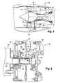
- FIG 1 represents a turbomachine comprising, upstream to downstream, a fan 12, a low-pressure compressor 14, an intermediate casing 16, a high-pressure compressor 18, a combustion chamber 20, a high-pressure turbine 21 and a low-pressure turbine 22
- the air entering the turbomachine is divided into a primary air flow (arrow A) which circulates inside the low and high pressure compressors 14, 18 to the combustion chamber 20 and then through the high and low turbines.
- pressure 21, 22, and a secondary air flow (arrows B) which bypasses the compressor 14, 18, the combustion chamber 20 and the turbine 21, 22.
- the intermediate casing 16 comprises structural arms 24 extending radially outwardly.
- One of the arms 24 of the intermediate casing 16 contains a radial shaft 26 whose inner end is connected by a pair of bevel gears to the drive shaft 28 of the high-pressure compressor 18.
- the radially outer end of the radial shaft 26 is connected by another pair of bevel gears to the input of a gearbox 32, comprising driving gears of a plurality of equipment, such as for example, an oil pump, a hydraulic pump, a fuel pump, a starter and an electric generator.
- the figure 2 represents a part of a gearbox 32 according to the prior art.
- a gearbox 32 comprises a front side wall 34 and a rear side wall 36 between which a plurality of transmission shafts 38 each coupled to a rotating equipment 40 extend.
- the transmission shaft 38 is guided in rotation at its ends in two rolling bearings, one of which is ball bearings and the other 44 is roller.
- the bearings 42, 44 each comprise an inner ring 46 carried by the transmission shaft 38 and an outer ring 48 fixed by means of screws 50 on bosses 52 of the front walls 34 or rear 36.
- Each bearing 42, 44 is supplied with oil by a specific lubrication circuit.
- the transmission shaft 38 carries a toothed wheel 54 arranged between the two rolling bearings 42, 44 and engaged with a drive pinion 56.
- the housing 40 of an equipment is fixed by screwing or by a clamping collar on the front side wall 34.
- This equipment comprises a drive shaft 58 whose outer surface comprises axial splines engaged in complementary axial grooves of the drive shaft 38.
- the invention provides a solution to this drawback as well as to those mentioned above by replacing the rolling bearing ball by a sliding bearing 60 and moving the roller bearing 62 in the radial plane of the drive pinion 56.
- the transmission shaft 64 has a substantially cylindrical portion before 66 whose end is engaged and guided in rotation in a ring 68 of the sliding bearing 60.
- This ring is mounted in a bore of the front wall 34 of the box.
- gears 61 and comprises a flange 70 fixed by screws on the front wall 34.
- the rear end of the transmission shaft 64 comprises a cylindrical bearing surface 72 carrying the inner ring 74 of the roller bearing 62.
- the outer ring 76 of this bearing is carried by the front end of a cylindrical end piece 78 integral with the rear wall 36 of the gearbox 61.
- the rear end of the outer ring 76 integral with the endpiece 78 comprises a radial annular flange 79 facing inwards.
- the shaft 64 comprises a shoulder 81 on which rests the rear end of a ring 83 comprising at its front end a radial annular flange 85.
- the ring 83 is dimensioned axially so that the annular flange 85 is spaced from the rear end of the fixed ring 68 with a clearance identical to that separating the roller bearing from the stop 79.
- the two annular flanges 79, 85 form axial stops limiting the displacement of the rotor line due to sliding of the roller bearing on its track. These stops 79, 85 thus make it possible to maintain the alignment of the bearing 62 with the toothed wheel 56.
- the toothed wheel 78 carried by the shaft 64 is engaged at its outer periphery with the drive pinion 56.
- the teeth engaged with the wheel and the pinion are situated in a radial plane passing through the roller bearing 62.
- toothed wheel 78 is connected to the front end of the reach cylindrical 72 by a wall of revolution comprising a first outer portion 82 substantially radial and a second frustoconical inner portion 84 connected to the cylindrical seat 72. This frustoconical wall portion 84 releases on the shaft 64 a space that can be used to the mounting of the roller bearing 62 to the right of the drive pinion 56.
- the end piece 86 bearing the outer ring 76 is integral with the front wall 34 of the gear box.
- a toothed wheel 88 connected to the rear end of the shaft 64 comprises a first frustoconical outer portion 90 bearing a toothing meshing with the toothing of the pinion 56 and a second substantially radial inner portion 92.
- the radial load can be completely taken up by the roller bearing 62 while the plain bearing 60 serves to prevent the transmission shaft 64 from tilting.
- the radial dimension of the plain bearing 60 can be reduced. compared to that of a ball bearing.
- Such a plain bearing 60 is also more reliable than a rolling ball bearing and does not necessarily require specific lubrication circuit.
- the invention is not limited to the use of a roller bearing as described with reference to Figures 3 and 4 and it would be possible to replace the roller bearing with a ball bearing.
Landscapes
- Engineering & Computer Science (AREA)
- General Engineering & Computer Science (AREA)
- Mechanical Engineering (AREA)
- Chemical & Material Sciences (AREA)
- Combustion & Propulsion (AREA)
- General Details Of Gearings (AREA)
- Rolling Contact Bearings (AREA)
- Turbine Rotor Nozzle Sealing (AREA)
- Gear Transmission (AREA)
Description
- La présente invention concerne une boîte d'engrenages destinée à l'entraînement en rotation d'équipements d'une turbomachine.
- Dans une turbomachine, différents équipements, tels que notamment des pompes pour la production d'énergie hydraulique, l'alimentation en carburant, la lubrification, des générateurs électriques pour la production de puissance électrique, etc., sont entraînés en rotation par une boîte d'engrenages reliée à un arbre de la turbomachine.
- Chaque équipement comprend un arbre tournant couplé en rotation à un arbre de transmission de la boîte d'engrenages. Cet arbre de transmission porte extérieurement une roue dentée qui est en prise avec un pignon d'entraînement lequel est couplé par un train d'engrenages à un arbre de compresseur de la turbomachine.
- L'arbre de transmission est guidé en rotation à ses extrémités dans deux paliers à roulement dont les bagues externes sont fixées sur des parois de la boîte d'engrenages. Le document
DE 3830 446 A1 décrit une boîte d'engrenages comme disposée dans le préambule de la revendication indépendante 1. - Afin de réduire les coûts des boîtes d'engrenages, on a recours à des roulements standardisés. De ce fait, les roulements utilisés sont souvent surdimensionnés par rapport à l'utilisation requise. L'utilisation de roulements spécialement adaptés aux utilisations prévues permettrait de réduire la masse de la boîte d'engrenages mais de façon très faible puisque cela n'aurait que peu ou pas d'impact sur le dimensionnement de la boîte d'engrenages, des différents éléments de visserie, des moyens de lubrification, etc.
- Les parois de la boîte d'engrenages comprennent également des bossages de montage des paliers à roulement. Ces parties de la boîte sont également renforcées pour permettre le passage des efforts en fonctionnement, ce qui conduit à alourdir la boîte d'engrenages. De plus, chaque palier nécessite un circuit spécifique de lubrification, ce qui complique encore la conception de la boîte d'engrenages.
- La présente invention a notamment pour but d'apporter une solution simple, efficace et économique à ces problèmes de la technique actuelle.
- A cet effet, elle propose une boîte d'engrenages dans une turbomachine pour l'entraînement en rotation d'au moins un équipement tournant, tel par exemple qu'un alternateur ou une pompe, comprenant un arbre de transmission guidé en rotation dans des paliers et portant une roue dentée en prise avec au moins un pignon d'entraînement en rotation, caractérisée en ce que l'un des paliers est un palier à roulement monté à l'intérieur de la roue dentée et dans un plan radial contenant la roue dentée et le pignon d'entraînement et en ce qu'un autre palier est un palier lisse de reprise d'efforts de basculement de l'arbre de transmission.
- Selon l'invention, l'arbre de transmission n'est plus guidé que par un seul palier à roulement, l'autre palier étant un palier lisse qui est dépourvu d'éléments roulants. L'agencement du palier à roulement dans le plan radial contenant la roue dentée et le pignon d'entraînement permet de reprendre toute la charge radiale de l'engrènement entre la roue dentée et le pignon d'entraînement.
- Le palier lisse n'assure pas la reprise des efforts radiaux mais uniquement la reprise des efforts de basculement de l'arbre de transmission. Il est donc possible de réduire beaucoup sa dimension, ce qui permet d'envisager une optimisation de la masse de la boîte d'engrenages.
- Le remplacement d'un palier à roulement par un palier lisse permet de réduire le nombre de pièces à coût élevé dans la boîte d'engrenages. De plus, dans la mesure où le palier lisse est faiblement chargé comme c'est le cas dans les boites d'engrenages selon l'invention, il ne nécessite pas d'alimentation spécifique en huile et s'avère plus fiable qu'un palier à roulement. La lubrification du palier lisse est en effet réalisée par le brouillard d'huile environnant.
- Selon une autre caractéristique de l'invention, les deux paliers sont montés aux extrémités de l'arbre de transmission.
- Avantageusement, le déplacement axial de l'arbre dans la boite d'engrenages selon l'invention est limité par deux butées axiales dont l'une est formée par un rebord annulaire de l'extrémité arrière de la bague externe du palier à roulement et l'autre est formée par un rebord annulaire avant de l'arbre de transmission coopérant avec l'extrémité arrière d'une bague fixe du palier lisse.
- Ces deux butées permettent de limiter le déplacement axial de l'arbre de transmission dû au glissement du roulement sur sa piste et permet ainsi de garantir un bon alignement radial du roulement et de la roue dentée.
- Selon encore une autre caractéristique de l'invention, la roue dentée est reliée à l'arbre de transmission par une paroi tronconique.
- Avantageusement, le palier lisse comprend une bague montée dans un alésage d'une paroi de la boîte d'engrenages.
- Selon une autre caractéristique de l'invention, l'extrémité de l'arbre de transmission guidée en rotation dans le palier lisse forme un moyeu à surface interne cannelée destiné à recevoir une extrémité cannelée d'un arbre rotatif de l'équipement tournant.
- Le palier lisse peut être en bronze ou en matériau composite.
- Selon encore une autre caractéristique de l'invention, le palier à roulement comprend une bague interne montée sur une portée cylindrique de l'arbre de transmission et une bague externe portée par un embout cylindrique solidaire d'une paroi de la boîte d'engrenages.
- Le palier à roulement peut être un palier du type à rouleaux ou à billes. Le palier à rouleaux présente l'avantage par rapport à un palier à roulement à billes d'assurer une meilleure reprise des charges radiales d'engrènement de la roue dentée.
- L'invention concerne également une turbomachine, telle qu'un turboréacteur ou un turbopropulseur, comprenant une boîte d'engrenages telle que décrite précédemment.
- L'invention sera mieux comprise et d'autres détails, avantages et caractéristiques de l'invention apparaîtront à la lecture de la description suivante faite à titre d'exemple non limitatif, en référence aux dessins annexés dans lesquels :
- la
figure 1 est une vue schématique en coupe axiale d'une turbomachine ; - la
figure 2 est une vue schématique en coupe axiale d'une partie d'une boîte d'engrenages selon la technique antérieure ; - la
figure 3 est une vue schématique en coupe axiale d'une partie d'une boîte d'engrenages selon l'invention - la
figure 4 est une vue schématique en coupe axiale d'une variante de réalisation de la boite d'engrenages selon l'invention. - On se réfère tout d'abord à la
figure 1 , qui représente une turbomachine 10 comprenant d'amont en aval une soufflante 12, un compresseur basse pression 14, un carter intermédiaire 16, un compresseur haute pression 18, une chambre de combustion 20, une turbine haute pression 21 et une turbine basse pression 22. L'air entrant dans la turbomachine se divise en un flux d'air primaire (flèche A) qui circule à l'intérieur des compresseurs basse et haute pression 14, 18 vers la chambre de combustion 20 puis à travers les turbines haute et basse pression 21, 22, et en un flux d'air secondaire (flèches B) qui contourne le compresseur 14, 18, la chambre de combustion 20 et la turbine 21, 22. - Le carter intermédiaire 16 comprend des bras structuraux 24 s'étendant radialement vers l'extérieur. Un des bras 24 du carter intermédiaire 16 contient un arbre radial 26 dont l'extrémité interne est reliée par un couple de pignons coniques à l'arbre d'entraînement 28 du compresseur haute pression 18. L'extrémité radialement externe de l'arbre radial 26 est reliée par un autre couple de pignons coniques à l'entrée d'une boîte d'engrenages 32, comportant des pignons d'entraînement d'une pluralité d'équipements, tels que par exemple, une pompe à huile, une pompe hydraulique, une pompe à carburant, un démarreur et un générateur électrique.
- La
figure 2 représente une partie d'une boîte d'engrenages 32 selon la technique antérieure. Une telle boîte d'engrenages 32 comprend une paroi latérale avant 34 et une paroi latérale arrière 36 entre lesquelles s'étendent une pluralité d'arbres de transmission 38 chacun couplé à un équipement tournant 40. - L'arbre de transmission 38 est guidé en rotation à ses extrémités dans deux paliers à roulement dont l'un 42 est à billes et l'autre 44 est à rouleaux. Les paliers 42, 44 comprennent chacun une bague interne 46 portée par l'arbre de transmission 38 et une bague externe 48 fixée au moyen de vis 50 sur des bossages 52 des parois avant 34 ou arrière 36. Chaque palier 42, 44 est alimenté en huile par un circuit spécifique de lubrification.
- L'arbre de transmission 38 porte une roue dentée 54 agencée entre les deux paliers à roulement 42, 44 et en prise avec un pignon d'entraînement 56.
- Le boîtier 40 d'un équipement est fixé par vissage ou par un collier de fixation sur la paroi latérale avant 34. Cet équipement comprend un arbre d'entraînement 58 dont la surface externe comporte des cannelures axiales engagées dans des cannelures axiales complémentaires de l'arbre de transmission 38.
- En fonctionnement, les charges radiales dues à l'engrènement entre la roue dentée 54 et le pignon d'entraînement 56 sont reprises par les deux paliers 42 et 44.
- Ce type de configuration n'est toutefois pas satisfaisant car il impose l'utilisation de deux paliers à roulement 42, 44 standardisés qui sont souvent surdimensionnés.
- L'invention apporte une solution à cet inconvénient ainsi qu'à ceux mentionnés précédemment en remplaçant le palier à roulement à billes par un palier lisse 60 et en déplaçant le palier à rouleaux 62 dans le plan radial du pignon d'entraînement 56.
- Comme représenté en
figure 3 , l'arbre de transmission 64 comporte une partie sensiblement cylindrique avant 66 dont l'extrémité est engagée et guidée en rotation dans une bague 68 du palier lisse 60. Cette bague est montée dans un alésage de la paroi avant 34 de la boîte d'engrenages 61 et comprend un rebord 70 fixé par des vis sur la paroi avant 34. - L'extrémité arrière de l'arbre de transmission 64 comprend une portée cylindrique 72 portant la bague interne 74 du palier à rouleaux 62. La bague externe 76 de ce palier est portée par l'extrémité avant d'un embout cylindrique 78 solidaire de la paroi arrière 36 de la boîte d'engrenages 61.
- L'extrémité arrière de la bague externe 76 solidaire de l'embout 78 comprend un rebord annulaire radial 79 orienté vers l'intérieur. L'arbre 64 comprend un épaulement 81 sur lequel s'appuie l'extrémité arrière d'un anneau 83 comprenant à son extrémité avant un rebord annulaire radial 85. L'anneau 83 est dimensionné axialement de manière à ce que le rebord annulaire 85 soit espacé de l'extrémité arrière de la bague fixe 68 d'un jeu identique à celui séparant le roulement à rouleaux de la butée 79. Les deux rebords annulaires 79, 85 forment des butées axiales limitant le déplacement de la ligne de rotor du fait du glissement du roulement à rouleaux sur sa piste. Ces butées 79, 85 permettent ainsi de maintenir l'alignement du roulement 62 avec la roue dentée 56.
- L'intégration d'une butée 85 limitant le glissement de l'arbre 64 vers la paroi arrière 36 est rendue nécessaire par le fait que l'on utilise un palier lisse 60 au lieu d'un palier à roulement lequel intégrait antérieurement un rebord annulaire formant la seconde butée axiale.
- La roue dentée 78 portée par l'arbre 64 est en prise à sa périphérie externe avec le pignon d'entraînement 56. Les dentures en prise de la roue et du pignon sont situées dans un plan radial passant par le palier à rouleaux 62. La roue dentée 78 est reliée à l'extrémité avant de la portée cylindrique 72 par une paroi de révolution comprenant une première partie externe 82 sensiblement radiale et une deuxième partie interne tronconique 84 reliée à la portée cylindrique 72. Cette partie de paroi tronconique 84 libère sur l'arbre 64 un espace que l'on peut utiliser pour le montage du palier à rouleaux 62 au droit du pignon d'entraînement 56.
- Dans une variante de réalisation de l'invention représentée en
figure 4 , l'embout 86 portant la bague externe 76 est solidaire de la paroi avant 34 de la boite d'engrenages. Dans cette réalisation, une roue dentée 88 reliée à l'extrémité arrière de l'arbre 64 comprend une première partie externe tronconique 90 portant une denture en prise avec une denture du pignon 56 et une deuxième partie interne sensiblement radiale 92. Avec ce montage, l'arbre 64 et les deux paliers 60, 62 sont portés par la paroi avant 34 de la boite d'engrenages, ce qui permet de réaliser un montage par l'avant plus simple de l'ensemble précité. Le maintien axial de l'arbre 64 est réalisé de manière identique à ce qui a été décrit en référence à lafigure 3 . - Grâce au montage selon l'invention, la charge radiale peut être reprise intégralement par le palier à rouleaux 62 tandis que le palier lisse 60 sert à éviter le basculement de l'arbre de transmission 64. La dimension radiale du palier lisse 60 peut être réduite en comparaison de celle d'un palier à roulement à billes. Un tel palier lisse 60 s'avère également plus fiable qu'un palier à roulement à billes et ne nécessite pas obligatoirement de circuit de lubrification spécifique.
- L'invention n'est pas limitée à l'utilisation d'un palier à rouleaux comme décrit en référence aux
figures 3 et 4 et il serait possible de remplacer le palier à rouleaux par un palier à roulement à billes. - Bien qu'en
figure 3 , un seul équipement 40 soit visible, il est clair que l'invention est applicable à tous les arbres de transmission de la boîte d'engrenages.
Claims (11)
- Boîte d'engrenages (61) dans une turbomachine pour l'entraînement en rotation d'au moins un équipement tournant, tel par exemple qu'un alternateur ou une pompe, comprenant un arbre de transmission (64) guidé en rotation dans des paliers (60, 62) et portant une roue dentée (78) en prise avec au moins un pignon d'entraînement (56) en rotation, caractérisée en ce que l'un des paliers est un palier à roulement (62) monté à l'intérieur de la roue dentée (78) et dans un plan radial contenant la roue dentée (78) et le pignon d'entraînement (56) et en ce qu'un autre palier est un palier lisse (60) de reprise d'efforts de basculement de l'arbre de transmission.
- Boîte selon la revendication 1, caractérisée en ce que les deux paliers (60, 62) sont montés aux extrémités de l'arbre de transmission (64).
- Boîte selon la revendication 1 ou 2, caractérisée en ce que le palier lisse (60) comprend une bague (68) montée dans un alésage d'une paroi (34) de la boîte d'engrenages.
- Boîte selon la revendication 3, caractérisée en ce qu'une extrémité de l'arbre de transmission (64) est guidée en rotation dans le palier lisse (60).
- Boîte selon l'une des revendications 1 à 4, caractérisée en ce que le palier lisse (60) est en bronze ou en matériau composite.
- Boîte selon l'une des revendications 1 à 5, caractérisée en ce que le palier à roulement (62) comprend une bague interne (74) montée sur l'arbre de transmission (64) et une bague externe (76) portée par un embout cylindrique (78) solidaire d'une paroi (34, 36) de la boîte d'engrenages (61).
- Boite selon la revendication 6, caractérisée en ce que le déplacement axial de l'arbre (64) est limité par deux butées axiales (79, 85) dont l'une est formée par un rebord annulaire de l'extrémité arrière de la bague externe (76) et l'autre est formée par un rebord annulaire avant de l'arbre de transmission (64) coopérant avec une extrémité arrière d'une bague fixe (68) du palier lisse (60).
- Boîte selon l'une des revendications 1 à 7, caractérisée en ce que la roue dentée (78) est reliée à l'arbre de transmission (64) par une paroi tronconique (84, 90).
- Boîte selon l'une des revendications 1 à 8, caractérisée en ce que l'extrémité de l'arbre de transmission (64) guidée par le palier lisse (60) forme un moyeu à surface interne cannelée destiné à recevoir une extrémité cannelée d'un arbre rotatif (58) de l'équipement tournant.
- Boîte selon l'une des revendications 1 à 9, caractérisée en ce que le palier à roulement est un palier du type à rouleaux ou à billes.
- Turbomachine, telle qu'un turboréacteur ou un turbopropulseur, caractérisée en ce qu'elle comprend une boîte d'engrenages (61) selon l'une des revendications 1 à 10.
Applications Claiming Priority (2)
| Application Number | Priority Date | Filing Date | Title |
|---|---|---|---|
| FR1054038A FR2960612B1 (fr) | 2010-05-25 | 2010-05-25 | Boite d'engrenages dans une turbomachine |
| PCT/FR2011/051107 WO2011148078A2 (fr) | 2010-05-25 | 2011-05-17 | Boite d'engrenages dans une turbomachine |
Publications (2)
| Publication Number | Publication Date |
|---|---|
| EP2576995A2 EP2576995A2 (fr) | 2013-04-10 |
| EP2576995B1 true EP2576995B1 (fr) | 2014-08-06 |
Family
ID=43618284
Family Applications (1)
| Application Number | Title | Priority Date | Filing Date |
|---|---|---|---|
| EP11727220.3A Active EP2576995B1 (fr) | 2010-05-25 | 2011-05-17 | Boite d'engrenages dans une turbomachine |
Country Status (8)
| Country | Link |
|---|---|
| US (1) | US20130104681A1 (fr) |
| EP (1) | EP2576995B1 (fr) |
| JP (1) | JP5850924B2 (fr) |
| CN (1) | CN102947550B (fr) |
| BR (1) | BR112012029274A2 (fr) |
| CA (1) | CA2799661A1 (fr) |
| FR (1) | FR2960612B1 (fr) |
| WO (1) | WO2011148078A2 (fr) |
Families Citing this family (8)
| Publication number | Priority date | Publication date | Assignee | Title |
|---|---|---|---|---|
| FR2979964B1 (fr) * | 2011-09-08 | 2014-04-11 | Turbomeca | Amortissement des vibrations d'un pignon par patch viscoelastique |
| DE102012018603A1 (de) | 2012-09-20 | 2014-03-20 | Rolls-Royce Deutschland Ltd & Co Kg | Hilfsgerätegetriebevorrichtung |
| FR3007462B1 (fr) * | 2013-06-21 | 2017-11-24 | Hispano-Suiza | Boitier d'accessoires de turbomachine equipe d'une pompe centrifuge |
| DE102013226527A1 (de) * | 2013-12-18 | 2015-06-18 | Zf Friedrichshafen Ag | Kombinierte Wälz- und Gleitlagerung einer Getriebewelle |
| FR3018860B1 (fr) * | 2014-03-21 | 2021-10-15 | Hispano Suiza Sa | Relais d'accessoires pour moteur a turbine a gaz |
| FR3045759B1 (fr) | 2015-12-21 | 2018-01-19 | Safran Transmission Systems | Mecanisme de transmission comprenant un organe d'accouplement, turbomachine equipee d'un tel mecanisme et procede de fonctionnement dudit mecanisme |
| FR3064306B1 (fr) * | 2017-03-27 | 2019-03-22 | Safran Transmission Systems | Relais d'accessoires pour moteur a turbine a gaz |
| FR3109960B1 (fr) * | 2020-05-07 | 2022-07-15 | Safran Trans Systems | Relais d’accessoires |
Family Cites Families (38)
| Publication number | Priority date | Publication date | Assignee | Title |
|---|---|---|---|---|
| US1421918A (en) * | 1919-03-03 | 1922-07-04 | Pyle National Co | Bearing for steam turbines |
| US1936566A (en) * | 1927-05-17 | 1933-11-21 | Davenport Robert Earl | Means for governing prime movers |
| US2561090A (en) * | 1942-11-18 | 1951-07-17 | Vickers Electrical Co Ltd | Power plant, including normally contrarotating turbine elements for driving a load shaft and means for rotating said elements in the same direction when the turbine is idling |
| US2590312A (en) * | 1947-01-31 | 1952-03-25 | Parker Appliance Co | Differential fuel regulator for turbojet engines |
| US2492020A (en) * | 1947-07-26 | 1949-12-20 | Westinghouse Electric Corp | Scavenging system for air propeller gear drives |
| US2803943A (en) * | 1953-12-30 | 1957-08-27 | Armstrong Siddeley Motors Ltd | Means for supporting and driving accessories which are exterior to a ductedfan turbo-jet engine |
| US2807052A (en) * | 1955-04-05 | 1957-09-24 | Warner Swasey Co | Drive shaft and shear coupling |
| US2908187A (en) * | 1955-05-19 | 1959-10-13 | Illinois Tool Works | Reduction gearing unit |
| US2980391A (en) * | 1956-04-19 | 1961-04-18 | Waterous Co | Solenoid operated priming valve |
| US3330476A (en) * | 1965-01-22 | 1967-07-11 | Hispano Suiza Sa | Rotor apparatus mechanically driven from a power relay |
| US3518897A (en) * | 1968-10-28 | 1970-07-07 | Rockwell Standard Co | Reduction gearing assembly |
| US3547241A (en) * | 1969-04-30 | 1970-12-15 | American Fire Pump Co | Positive clutch with friction synchronizing means |
| US3650634A (en) * | 1970-11-06 | 1972-03-21 | Carrier Corp | Centrifugal refrigeration compressor |
| US3734637A (en) * | 1971-05-13 | 1973-05-22 | Sundstrand Corp | Centrifugal pump |
| US3982390A (en) * | 1974-08-22 | 1976-09-28 | General Motors Corporation | Gas turbine engine cooling system |
| JPS5938440B2 (ja) * | 1975-01-31 | 1984-09-17 | 株式会社日立製作所 | 流体回転機械 |
| SE402147B (sv) * | 1975-12-05 | 1978-06-19 | United Turbine Ab & Co | Gasturbinanleggning med tre i samma gaspassage anordnade koaxiella turbinrotorer |
| US4030377A (en) * | 1976-06-28 | 1977-06-21 | Caterpillar Tractor Co. | Rotary drive assembly |
| US4157013A (en) * | 1977-09-08 | 1979-06-05 | General Motors Corporation | Water cooled automotive gas turbine engine |
| US4261225A (en) * | 1979-02-16 | 1981-04-14 | Maplan Maschinen- Und Technische Anlagen, Planungs- Und Fertigungs-Gesellschaft Mbh | Step-down transmission for driving a plurality of extrusion screws |
| US4226136A (en) * | 1979-05-24 | 1980-10-07 | Illinois Tool Works Inc. | Gear drive assembly |
| DE3485247D1 (de) * | 1983-09-22 | 1991-12-12 | Ebara Corp | Rotierende gasmaschine. |
| JPS6088222A (ja) * | 1983-10-21 | 1985-05-18 | Daido Metal Kogyo Kk | 複合摺動体 |
| US4825645A (en) * | 1987-09-08 | 1989-05-02 | General Motors Corporation | Power turbine and reduction gear assembly |
| DE3828508C1 (fr) * | 1988-08-23 | 1989-12-07 | Maschinenfabrik Stromag Gmbh, 4750 Unna, De | |
| US4902144A (en) * | 1989-05-02 | 1990-02-20 | Allied-Signal, Inc. | Turbocharger bearing assembly |
| IT1280474B1 (it) * | 1995-11-08 | 1998-01-20 | Maris Flli Spa | Riduttore ad ingranaggi perfezionato. |
| FI102004B1 (fi) * | 1996-01-10 | 1998-09-30 | Valmet Voimansiirto Oy | Vaihteisto |
| US6183388B1 (en) * | 1996-03-12 | 2001-02-06 | Allison Engine Company, Inc. | Epicyclic face gear reduction gearbox particularly for a gas turbine engine |
| JP3521043B2 (ja) * | 1996-05-15 | 2004-04-19 | 株式会社デンソー | 内燃機関用点火装置 |
| US5816102A (en) * | 1996-12-03 | 1998-10-06 | Generac Corporation | Engine-generator set with integral gear reduction |
| DE10102012A1 (de) * | 2001-01-18 | 2002-08-01 | Bosch Gmbh Robert | Gleitlager |
| JP2005172098A (ja) * | 2003-12-10 | 2005-06-30 | Koyo Seiko Co Ltd | ターボチャージャの軸受装置 |
| US7055330B2 (en) * | 2004-02-25 | 2006-06-06 | United Technologies Corp | Apparatus for driving an accessory gearbox in a gas turbine engine |
| FR2877036B1 (fr) * | 2004-10-27 | 2006-12-22 | Snecma Moteurs Sa | Dispositif de lubrification d'un composant dans une turbomachine |
| FR2880920B1 (fr) * | 2005-01-20 | 2007-07-06 | Snecma Moteurs Sa | Turbomoteur a double corps avec des moyens d'entrainement du boitier d'accessoires |
| US7805947B2 (en) * | 2005-05-19 | 2010-10-05 | Djamal Moulebhar | Aircraft with disengageable engine and auxiliary power unit components |
| FR2905414B1 (fr) * | 2006-08-29 | 2013-03-01 | Snecma | Dispositif d'entrainement du rotor d'un equipement auxiliaire d'un turbomoteur. |
-
2010
- 2010-05-25 FR FR1054038A patent/FR2960612B1/fr not_active Expired - Fee Related
-
2011
- 2011-05-17 JP JP2013511724A patent/JP5850924B2/ja not_active Expired - Fee Related
- 2011-05-17 BR BR112012029274A patent/BR112012029274A2/pt not_active IP Right Cessation
- 2011-05-17 CN CN201180025615.4A patent/CN102947550B/zh active Active
- 2011-05-17 EP EP11727220.3A patent/EP2576995B1/fr active Active
- 2011-05-17 WO PCT/FR2011/051107 patent/WO2011148078A2/fr not_active Ceased
- 2011-05-17 CA CA2799661A patent/CA2799661A1/fr not_active Abandoned
- 2011-05-17 US US13/699,949 patent/US20130104681A1/en not_active Abandoned
Also Published As
| Publication number | Publication date |
|---|---|
| US20130104681A1 (en) | 2013-05-02 |
| CN102947550A (zh) | 2013-02-27 |
| RU2012156216A (ru) | 2014-06-27 |
| BR112012029274A2 (pt) | 2016-07-26 |
| CA2799661A1 (fr) | 2011-12-01 |
| WO2011148078A2 (fr) | 2011-12-01 |
| FR2960612B1 (fr) | 2012-06-22 |
| FR2960612A1 (fr) | 2011-12-02 |
| CN102947550B (zh) | 2015-09-09 |
| WO2011148078A3 (fr) | 2012-01-19 |
| JP2013527377A (ja) | 2013-06-27 |
| JP5850924B2 (ja) | 2016-02-03 |
| EP2576995A2 (fr) | 2013-04-10 |
Similar Documents
| Publication | Publication Date | Title |
|---|---|---|
| CA2938385C (fr) | Turbomachine equipee d'un groupe de lubrification | |
| EP3071792B1 (fr) | Moteur modulaire | |
| EP3137741B1 (fr) | Turbomachine d'aéronef a prélèvement de puissance mécanique amélioré | |
| WO2011148078A2 (fr) | Boite d'engrenages dans une turbomachine | |
| EP3705705B1 (fr) | Réducteur mécanique de turbomachine d'aéronef | |
| EP3999729B1 (fr) | Réducteur à train épicycloïdal pour une turbomachine | |
| FR3084427A1 (fr) | Dispositif de type reducteur mecanique pour une turbomachine | |
| EP3999730B1 (fr) | Réducteur à train épicycloïdal pour une turbomachine | |
| WO2019053371A1 (fr) | Pivot pour palier lisse | |
| EP3763932B1 (fr) | Reducteur mécanique pour une turbomachine d'aéronef | |
| EP3350476B1 (fr) | Boitier d'entrainement d'equipements dans une turbomachine | |
| EP3601747B1 (fr) | Relais d'accessoires pour moteur a turbine a gaz | |
| EP3011157A1 (fr) | Boitier d'accessoires de turbomachine equipe d'une pompe centrifuge | |
| EP3755894B1 (fr) | Assemblage de maintien d'un train d'engrenages dans une turbomachine | |
| EP3736428B1 (fr) | Gorge de joint rapportée pour accouplement par cannelures | |
| EP4267839A1 (fr) | Module de turbomachine equipe d'une machine electrique et turbomachine equipee d'un tel module | |
| EP3810911B1 (fr) | Turbomachine d'aéronef à au moins deux corps et prélèvement de puissance | |
| EP4411178B1 (fr) | Turbomachine comprenant un reducteur de vitesse ayant des brides de fixation accouplees par un accouplement a dentures | |
| FR3135753A1 (fr) | Boitier de relais d’accessoires pour une turbomachine | |
| WO2025109274A1 (fr) | Turbomachine comprenant un reducteur de vitesse ayant des brides de fixation reliees a un stator de la turbomachine | |
| FR3162794A1 (fr) | Turbomachine d’aeronef comprenant un ensemble comportant un boitier d’accessoires et un equipement | |
| WO2025088266A1 (fr) | Transmission de puissance dans une turbomachine d'aeronef | |
| FR3135755A1 (fr) | Boitier de relais d’accessoires pour une turbomachine |
Legal Events
| Date | Code | Title | Description |
|---|---|---|---|
| PUAI | Public reference made under article 153(3) epc to a published international application that has entered the european phase |
Free format text: ORIGINAL CODE: 0009012 |
|
| 17P | Request for examination filed |
Effective date: 20121112 |
|
| AK | Designated contracting states |
Kind code of ref document: A2 Designated state(s): AL AT BE BG CH CY CZ DE DK EE ES FI FR GB GR HR HU IE IS IT LI LT LU LV MC MK MT NL NO PL PT RO RS SE SI SK SM TR |
|
| DAX | Request for extension of the european patent (deleted) | ||
| GRAJ | Information related to disapproval of communication of intention to grant by the applicant or resumption of examination proceedings by the epo deleted |
Free format text: ORIGINAL CODE: EPIDOSDIGR1 |
|
| GRAP | Despatch of communication of intention to grant a patent |
Free format text: ORIGINAL CODE: EPIDOSNIGR1 |
|
| GRAP | Despatch of communication of intention to grant a patent |
Free format text: ORIGINAL CODE: EPIDOSNIGR1 |
|
| RIN1 | Information on inventor provided before grant (corrected) |
Inventor name: GALIVEL, JEAN-PIERRE, ELIE |
|
| INTG | Intention to grant announced |
Effective date: 20140409 |
|
| GRAS | Grant fee paid |
Free format text: ORIGINAL CODE: EPIDOSNIGR3 |
|
| GRAA | (expected) grant |
Free format text: ORIGINAL CODE: 0009210 |
|
| AK | Designated contracting states |
Kind code of ref document: B1 Designated state(s): AL AT BE BG CH CY CZ DE DK EE ES FI FR GB GR HR HU IE IS IT LI LT LU LV MC MK MT NL NO PL PT RO RS SE SI SK SM TR |
|
| REG | Reference to a national code |
Ref country code: GB Ref legal event code: FG4D Free format text: NOT ENGLISH |
|
| REG | Reference to a national code |
Ref country code: CH Ref legal event code: EP Ref country code: AT Ref legal event code: REF Ref document number: 681178 Country of ref document: AT Kind code of ref document: T Effective date: 20140815 |
|
| REG | Reference to a national code |
Ref country code: IE Ref legal event code: FG4D Free format text: LANGUAGE OF EP DOCUMENT: FRENCH |
|
| REG | Reference to a national code |
Ref country code: DE Ref legal event code: R096 Ref document number: 602011008910 Country of ref document: DE Effective date: 20140918 |
|
| REG | Reference to a national code |
Ref country code: SE Ref legal event code: TRGR |
|
| REG | Reference to a national code |
Ref country code: AT Ref legal event code: MK05 Ref document number: 681178 Country of ref document: AT Kind code of ref document: T Effective date: 20140806 |
|
| REG | Reference to a national code |
Ref country code: NL Ref legal event code: VDEP Effective date: 20140806 |
|
| REG | Reference to a national code |
Ref country code: LT Ref legal event code: MG4D |
|
| PG25 | Lapsed in a contracting state [announced via postgrant information from national office to epo] |
Ref country code: BG Free format text: LAPSE BECAUSE OF FAILURE TO SUBMIT A TRANSLATION OF THE DESCRIPTION OR TO PAY THE FEE WITHIN THE PRESCRIBED TIME-LIMIT Effective date: 20141106 Ref country code: PT Free format text: LAPSE BECAUSE OF FAILURE TO SUBMIT A TRANSLATION OF THE DESCRIPTION OR TO PAY THE FEE WITHIN THE PRESCRIBED TIME-LIMIT Effective date: 20141209 Ref country code: LT Free format text: LAPSE BECAUSE OF FAILURE TO SUBMIT A TRANSLATION OF THE DESCRIPTION OR TO PAY THE FEE WITHIN THE PRESCRIBED TIME-LIMIT Effective date: 20140806 Ref country code: FI Free format text: LAPSE BECAUSE OF FAILURE TO SUBMIT A TRANSLATION OF THE DESCRIPTION OR TO PAY THE FEE WITHIN THE PRESCRIBED TIME-LIMIT Effective date: 20140806 Ref country code: ES Free format text: LAPSE BECAUSE OF FAILURE TO SUBMIT A TRANSLATION OF THE DESCRIPTION OR TO PAY THE FEE WITHIN THE PRESCRIBED TIME-LIMIT Effective date: 20140806 Ref country code: NO Free format text: LAPSE BECAUSE OF FAILURE TO SUBMIT A TRANSLATION OF THE DESCRIPTION OR TO PAY THE FEE WITHIN THE PRESCRIBED TIME-LIMIT Effective date: 20141106 Ref country code: GR Free format text: LAPSE BECAUSE OF FAILURE TO SUBMIT A TRANSLATION OF THE DESCRIPTION OR TO PAY THE FEE WITHIN THE PRESCRIBED TIME-LIMIT Effective date: 20141107 |
|
| PG25 | Lapsed in a contracting state [announced via postgrant information from national office to epo] |
Ref country code: NL Free format text: LAPSE BECAUSE OF FAILURE TO SUBMIT A TRANSLATION OF THE DESCRIPTION OR TO PAY THE FEE WITHIN THE PRESCRIBED TIME-LIMIT Effective date: 20140806 Ref country code: PL Free format text: LAPSE BECAUSE OF FAILURE TO SUBMIT A TRANSLATION OF THE DESCRIPTION OR TO PAY THE FEE WITHIN THE PRESCRIBED TIME-LIMIT Effective date: 20140806 Ref country code: CY Free format text: LAPSE BECAUSE OF FAILURE TO SUBMIT A TRANSLATION OF THE DESCRIPTION OR TO PAY THE FEE WITHIN THE PRESCRIBED TIME-LIMIT Effective date: 20140806 Ref country code: AT Free format text: LAPSE BECAUSE OF FAILURE TO SUBMIT A TRANSLATION OF THE DESCRIPTION OR TO PAY THE FEE WITHIN THE PRESCRIBED TIME-LIMIT Effective date: 20140806 Ref country code: RS Free format text: LAPSE BECAUSE OF FAILURE TO SUBMIT A TRANSLATION OF THE DESCRIPTION OR TO PAY THE FEE WITHIN THE PRESCRIBED TIME-LIMIT Effective date: 20140806 Ref country code: IS Free format text: LAPSE BECAUSE OF FAILURE TO SUBMIT A TRANSLATION OF THE DESCRIPTION OR TO PAY THE FEE WITHIN THE PRESCRIBED TIME-LIMIT Effective date: 20141206 Ref country code: LV Free format text: LAPSE BECAUSE OF FAILURE TO SUBMIT A TRANSLATION OF THE DESCRIPTION OR TO PAY THE FEE WITHIN THE PRESCRIBED TIME-LIMIT Effective date: 20140806 Ref country code: HR Free format text: LAPSE BECAUSE OF FAILURE TO SUBMIT A TRANSLATION OF THE DESCRIPTION OR TO PAY THE FEE WITHIN THE PRESCRIBED TIME-LIMIT Effective date: 20140806 |
|
| PG25 | Lapsed in a contracting state [announced via postgrant information from national office to epo] |
Ref country code: DK Free format text: LAPSE BECAUSE OF FAILURE TO SUBMIT A TRANSLATION OF THE DESCRIPTION OR TO PAY THE FEE WITHIN THE PRESCRIBED TIME-LIMIT Effective date: 20140806 Ref country code: RO Free format text: LAPSE BECAUSE OF FAILURE TO SUBMIT A TRANSLATION OF THE DESCRIPTION OR TO PAY THE FEE WITHIN THE PRESCRIBED TIME-LIMIT Effective date: 20140806 Ref country code: SK Free format text: LAPSE BECAUSE OF FAILURE TO SUBMIT A TRANSLATION OF THE DESCRIPTION OR TO PAY THE FEE WITHIN THE PRESCRIBED TIME-LIMIT Effective date: 20140806 Ref country code: EE Free format text: LAPSE BECAUSE OF FAILURE TO SUBMIT A TRANSLATION OF THE DESCRIPTION OR TO PAY THE FEE WITHIN THE PRESCRIBED TIME-LIMIT Effective date: 20140806 Ref country code: CZ Free format text: LAPSE BECAUSE OF FAILURE TO SUBMIT A TRANSLATION OF THE DESCRIPTION OR TO PAY THE FEE WITHIN THE PRESCRIBED TIME-LIMIT Effective date: 20140806 |
|
| REG | Reference to a national code |
Ref country code: DE Ref legal event code: R097 Ref document number: 602011008910 Country of ref document: DE |
|
| REG | Reference to a national code |
Ref country code: FR Ref legal event code: PLFP Year of fee payment: 5 |
|
| PLBE | No opposition filed within time limit |
Free format text: ORIGINAL CODE: 0009261 |
|
| STAA | Information on the status of an ep patent application or granted ep patent |
Free format text: STATUS: NO OPPOSITION FILED WITHIN TIME LIMIT |
|
| 26N | No opposition filed |
Effective date: 20150507 |
|
| PG25 | Lapsed in a contracting state [announced via postgrant information from national office to epo] |
Ref country code: SI Free format text: LAPSE BECAUSE OF FAILURE TO SUBMIT A TRANSLATION OF THE DESCRIPTION OR TO PAY THE FEE WITHIN THE PRESCRIBED TIME-LIMIT Effective date: 20140806 |
|
| REG | Reference to a national code |
Ref country code: CH Ref legal event code: PL |
|
| PG25 | Lapsed in a contracting state [announced via postgrant information from national office to epo] |
Ref country code: LU Free format text: LAPSE BECAUSE OF FAILURE TO SUBMIT A TRANSLATION OF THE DESCRIPTION OR TO PAY THE FEE WITHIN THE PRESCRIBED TIME-LIMIT Effective date: 20150517 Ref country code: CH Free format text: LAPSE BECAUSE OF NON-PAYMENT OF DUE FEES Effective date: 20150531 Ref country code: LI Free format text: LAPSE BECAUSE OF NON-PAYMENT OF DUE FEES Effective date: 20150531 Ref country code: MC Free format text: LAPSE BECAUSE OF FAILURE TO SUBMIT A TRANSLATION OF THE DESCRIPTION OR TO PAY THE FEE WITHIN THE PRESCRIBED TIME-LIMIT Effective date: 20140806 |
|
| REG | Reference to a national code |
Ref country code: IE Ref legal event code: MM4A |
|
| PG25 | Lapsed in a contracting state [announced via postgrant information from national office to epo] |
Ref country code: IE Free format text: LAPSE BECAUSE OF NON-PAYMENT OF DUE FEES Effective date: 20150517 |
|
| REG | Reference to a national code |
Ref country code: FR Ref legal event code: PLFP Year of fee payment: 6 |
|
| PG25 | Lapsed in a contracting state [announced via postgrant information from national office to epo] |
Ref country code: MT Free format text: LAPSE BECAUSE OF FAILURE TO SUBMIT A TRANSLATION OF THE DESCRIPTION OR TO PAY THE FEE WITHIN THE PRESCRIBED TIME-LIMIT Effective date: 20140806 |
|
| REG | Reference to a national code |
Ref country code: FR Ref legal event code: PLFP Year of fee payment: 7 |
|
| PG25 | Lapsed in a contracting state [announced via postgrant information from national office to epo] |
Ref country code: HU Free format text: LAPSE BECAUSE OF FAILURE TO SUBMIT A TRANSLATION OF THE DESCRIPTION OR TO PAY THE FEE WITHIN THE PRESCRIBED TIME-LIMIT; INVALID AB INITIO Effective date: 20110517 Ref country code: SM Free format text: LAPSE BECAUSE OF FAILURE TO SUBMIT A TRANSLATION OF THE DESCRIPTION OR TO PAY THE FEE WITHIN THE PRESCRIBED TIME-LIMIT Effective date: 20140806 |
|
| PG25 | Lapsed in a contracting state [announced via postgrant information from national office to epo] |
Ref country code: BE Free format text: LAPSE BECAUSE OF NON-PAYMENT OF DUE FEES Effective date: 20150531 |
|
| PG25 | Lapsed in a contracting state [announced via postgrant information from national office to epo] |
Ref country code: TR Free format text: LAPSE BECAUSE OF FAILURE TO SUBMIT A TRANSLATION OF THE DESCRIPTION OR TO PAY THE FEE WITHIN THE PRESCRIBED TIME-LIMIT Effective date: 20140806 |
|
| REG | Reference to a national code |
Ref country code: FR Ref legal event code: CD Owner name: SAFRAN AIRCRAFT ENGINES, FR Effective date: 20170717 |
|
| REG | Reference to a national code |
Ref country code: FR Ref legal event code: PLFP Year of fee payment: 8 |
|
| PG25 | Lapsed in a contracting state [announced via postgrant information from national office to epo] |
Ref country code: MK Free format text: LAPSE BECAUSE OF FAILURE TO SUBMIT A TRANSLATION OF THE DESCRIPTION OR TO PAY THE FEE WITHIN THE PRESCRIBED TIME-LIMIT Effective date: 20140806 |
|
| PG25 | Lapsed in a contracting state [announced via postgrant information from national office to epo] |
Ref country code: AL Free format text: LAPSE BECAUSE OF FAILURE TO SUBMIT A TRANSLATION OF THE DESCRIPTION OR TO PAY THE FEE WITHIN THE PRESCRIBED TIME-LIMIT Effective date: 20140806 |
|
| PGFP | Annual fee paid to national office [announced via postgrant information from national office to epo] |
Ref country code: DE Payment date: 20250519 Year of fee payment: 15 |
|
| PGFP | Annual fee paid to national office [announced via postgrant information from national office to epo] |
Ref country code: GB Payment date: 20250527 Year of fee payment: 15 |
|
| PGFP | Annual fee paid to national office [announced via postgrant information from national office to epo] |
Ref country code: IT Payment date: 20250530 Year of fee payment: 15 |
|
| PGFP | Annual fee paid to national office [announced via postgrant information from national office to epo] |
Ref country code: FR Payment date: 20250526 Year of fee payment: 15 |
|
| PGFP | Annual fee paid to national office [announced via postgrant information from national office to epo] |
Ref country code: SE Payment date: 20250522 Year of fee payment: 15 |