EP2576980B1 - Surface detection of failed open-hole packers using tubing with external tracer coatings - Google Patents
Surface detection of failed open-hole packers using tubing with external tracer coatings Download PDFInfo
- Publication number
- EP2576980B1 EP2576980B1 EP11787222.6A EP11787222A EP2576980B1 EP 2576980 B1 EP2576980 B1 EP 2576980B1 EP 11787222 A EP11787222 A EP 11787222A EP 2576980 B1 EP2576980 B1 EP 2576980B1
- Authority
- EP
- European Patent Office
- Prior art keywords
- tubing
- open
- length
- inflow control
- control device
- Prior art date
- Legal status (The legal status is an assumption and is not a legal conclusion. Google has not performed a legal analysis and makes no representation as to the accuracy of the status listed.)
- Not-in-force
Links
- 239000000700 radioactive tracer Substances 0.000 title claims description 67
- 238000000576 coating method Methods 0.000 title claims description 18
- 238000001514 detection method Methods 0.000 title description 4
- 238000004519 manufacturing process Methods 0.000 claims description 67
- 239000000203 mixture Substances 0.000 claims description 40
- 238000000034 method Methods 0.000 claims description 36
- 239000012530 fluid Substances 0.000 claims description 30
- 229930195733 hydrocarbon Natural products 0.000 claims description 30
- 150000002430 hydrocarbons Chemical class 0.000 claims description 29
- 239000004215 Carbon black (E152) Substances 0.000 claims description 26
- 239000003550 marker Substances 0.000 claims description 19
- 239000011435 rock Substances 0.000 claims description 14
- 238000012360 testing method Methods 0.000 claims description 14
- 239000011248 coating agent Substances 0.000 claims description 13
- 230000008878 coupling Effects 0.000 claims description 7
- 238000010168 coupling process Methods 0.000 claims description 7
- 238000005859 coupling reaction Methods 0.000 claims description 7
- 230000004888 barrier function Effects 0.000 claims description 2
- 238000004891 communication Methods 0.000 claims 2
- XLYOFNOQVPJJNP-UHFFFAOYSA-N water Substances O XLYOFNOQVPJJNP-UHFFFAOYSA-N 0.000 description 41
- 150000001875 compounds Chemical class 0.000 description 15
- 238000005070 sampling Methods 0.000 description 10
- 230000015572 biosynthetic process Effects 0.000 description 8
- 238000005755 formation reaction Methods 0.000 description 8
- 238000007789 sealing Methods 0.000 description 4
- 238000010586 diagram Methods 0.000 description 3
- 238000002347 injection Methods 0.000 description 3
- 239000007924 injection Substances 0.000 description 3
- BVKZGUZCCUSVTD-UHFFFAOYSA-L Carbonate Chemical compound [O-]C([O-])=O BVKZGUZCCUSVTD-UHFFFAOYSA-L 0.000 description 2
- 239000008199 coating composition Substances 0.000 description 2
- 230000000694 effects Effects 0.000 description 2
- 230000001788 irregular Effects 0.000 description 2
- 239000000463 material Substances 0.000 description 2
- 239000000523 sample Substances 0.000 description 2
- 238000000429 assembly Methods 0.000 description 1
- 230000000712 assembly Effects 0.000 description 1
- 239000012267 brine Substances 0.000 description 1
- 230000007547 defect Effects 0.000 description 1
- 230000001419 dependent effect Effects 0.000 description 1
- 230000009977 dual effect Effects 0.000 description 1
- 230000001747 exhibiting effect Effects 0.000 description 1
- 239000002360 explosive Substances 0.000 description 1
- 239000008398 formation water Substances 0.000 description 1
- 230000005251 gamma ray Effects 0.000 description 1
- 239000003673 groundwater Substances 0.000 description 1
- 125000001183 hydrocarbyl group Chemical group 0.000 description 1
- 230000008595 infiltration Effects 0.000 description 1
- 238000001764 infiltration Methods 0.000 description 1
- 238000012986 modification Methods 0.000 description 1
- 230000004048 modification Effects 0.000 description 1
- 238000012544 monitoring process Methods 0.000 description 1
- 239000003129 oil well Substances 0.000 description 1
- 230000002093 peripheral effect Effects 0.000 description 1
- 230000002285 radioactive effect Effects 0.000 description 1
- 150000003839 salts Chemical class 0.000 description 1
- HPALAKNZSZLMCH-UHFFFAOYSA-M sodium;chloride;hydrate Chemical compound O.[Na+].[Cl-] HPALAKNZSZLMCH-UHFFFAOYSA-M 0.000 description 1
- 239000007787 solid Substances 0.000 description 1
- 239000000243 solution Substances 0.000 description 1
- 239000000126 substance Substances 0.000 description 1
Images


Classifications
-
- E—FIXED CONSTRUCTIONS
- E21—EARTH OR ROCK DRILLING; MINING
- E21B—EARTH OR ROCK DRILLING; OBTAINING OIL, GAS, WATER, SOLUBLE OR MELTABLE MATERIALS OR A SLURRY OF MINERALS FROM WELLS
- E21B47/00—Survey of boreholes or wells
- E21B47/10—Locating fluid leaks, intrusions or movements
- E21B47/11—Locating fluid leaks, intrusions or movements using tracers; using radioactivity
-
- E—FIXED CONSTRUCTIONS
- E21—EARTH OR ROCK DRILLING; MINING
- E21B—EARTH OR ROCK DRILLING; OBTAINING OIL, GAS, WATER, SOLUBLE OR MELTABLE MATERIALS OR A SLURRY OF MINERALS FROM WELLS
- E21B33/00—Sealing or packing boreholes or wells
- E21B33/10—Sealing or packing boreholes or wells in the borehole
- E21B33/12—Packers; Plugs
- E21B33/124—Units with longitudinally-spaced plugs for isolating the intermediate space
-
- E—FIXED CONSTRUCTIONS
- E21—EARTH OR ROCK DRILLING; MINING
- E21B—EARTH OR ROCK DRILLING; OBTAINING OIL, GAS, WATER, SOLUBLE OR MELTABLE MATERIALS OR A SLURRY OF MINERALS FROM WELLS
- E21B43/00—Methods or apparatus for obtaining oil, gas, water, soluble or meltable materials or a slurry of minerals from wells
- E21B43/14—Obtaining from a multiple-zone well
Definitions
- This invention relates to a method used in the completion of horizontal sections of a subterranean hydrocarbon-producing well where no casing is installed, and specifically to the technique in which so-called open-hole packers are used for the purpose of forming compartments in the reservoir rock along the length of the horizontal pipe, or production tubing, that carries the produced hydrocarbon product to the surface.
- open-hole refers to the fact that no well casing pipe has been installed in the horizontal section, as it is typically installed in the vertical portion of the well bore.
- a principal objective of advance well completion is to have flow control over different inflow areas along the horizontal section of the well bore. This flow control is heavily dependent on the reliability of the open-hole packers that are installed to form isolated compartments defined by the production tubing and the surrounding reservoir rock wall that is the well bore.
- the purpose of installing the open-hole packers is to isolate the section of the production tubing that is perforated to receive the inflow of produced oil from the intervening spaces through which the remainder of the "blank" or imperforated tubing passes.
- the term blank tubing means production tubing that is not perforated and does not constitute an inflow control device (ICD) for admitting hydrocarbon fluids into the tubing for production to the earth's surface.
- ICD inflow control device
- the surface of the rock in the well bore can be irregular, even in carbonate formations. Such irregularities can interfere with the ability to form a reliable fluid-tight seal using the open-hole packer.
- What is required is a method for directly measuring the reliability of the open-hole packers to create the compartments in advanced well completions. This determination is particularly important from the standpoint of well management, and because of the high cost of installing the open-hole packers.
- tracers and tracer compositions in conjunction with well completions is known in the art.
- Several of the patents discussed below utilize tracers to identify the source of fluids produced from the reservoir and to identify specific locations or zones along the bore hole where the fluid(s) entered the bore hole.
- a method for monitoring hydrocarbon and water production from different production zones/sections in a reservoir and/or injection wells is disclosed in USP 6,645,769 .
- the method is said to be useful for differentiating between production of formation and/or injection water from various zones/sections and specifically for use in a "local alarm system” for water breakthrough.
- So-called “intelligent tracers” are used to distinguish between produced injection water and formation water from each zone/section.
- a specific tracer or tracers can be immobilized or placed on, e.g., a casing. The occurrence of a water breakthrough can be detected if the formation or a plug located in the formation releases a detectable tracer when the water or brine passes over the tracer composition and the released component is detected downstream.
- a method of determining the presence of undesired passageways that have been formed longitudinally between the bore hole wall and the inside peripheral wall of a casing are described in USP 3,848,124 .
- An undesirable passageway can be due to defects in a previous cementing job.
- Radioisotopes are placed adjacent to the casing at spaced-apart locations within the bore hole and on opposite sides of the production formation. The method appears to be limited to a bore hole in which the casing has been cemented in position by filling the annular space.
- the detection method seems to be limited to a gamma ray survey by logging the completed well.
- a known system for determining sealing in a wellbore is disclosed in WO2008/049835 .
- Some known ways for introducing tracers downhole for determining the origin of borehole fluids are disclosed in US7347260 .
- a known method for the determination of inflow of oil and/or gas into a well is also disclosed in US 5892147 .
- a dual packer element, having means incorporated therein for indicting leakage is disclosed in US2618341 .
- the method and assembly of the present invention which comprehends applying a water-soluble tracer composition and an oil-soluble tracer composition as coatings on at least a portion of the exterior surface of a section of blank production tubing that is positioned between one or more open-hole packers that define a non-flowing compartment that is proximate an inflow control device or devices in a horizontal well section. If the water-soluble tracer is detected at the surface in a produced oil-and-water mixture, it can be concluded that the open-hole packer is leaking water into the adjacent oil-producing section. If the oil-soluble tracer is detected at the surface, it can be concluded that the open-hole packer adjacent an ICD has failed and oil has contacted the coating.
- the method and apparatus of the invention is employed at the completion, or toe end of the bore hole to distinguish between water being co-produced from the hydrocarbon-bearing reservoir stratum and water from a previously penetrated water-bearing stratum.
- the water separated at the surface will be free of any water-soluble tracer composition.
- non-flowing compartment means a section of the horizontal well bore defined by a spaced-apart open-hole packer that does not contain an ICD.
- flowing compartment means a section that contains an ICD and includes the toe end of the tubing.
- the practice of the invention is not limited to any particular type of tracer composition or carrier.
- the principal requirement is that the tracer-containing composition can be applied to a length or portion of the production tubing that passes through the well bore to its final position at the completion end of the horizontal bore hole while maintaining its integrity as an exterior coating.
- the term "marker tubing” will be used herein to define a section of tubing, or a portion of tubing that has been coated with a water-soluble and/or oil soluble tracer compound or composition.
- the invention is thus directed to the use of a surface coating containing water-soluble and preferably both water-soluble and oil-soluble tracer compounds that are applied to the exterior surface of a section of pipe or production tubing, i.e., marker tubing, prior to its positioning in the well bore.
- the water-soluble tracer compound is soluble in produced formation fresh or salt water and/or such water that is pumped into the formation to enhance production.
- the oil-soluble tracer compounds are soluble in hydrocarbon fluids. In completions where multiple compartments are to be monitored, a different and distinguishable tracer compound will be applied to each compartmentalized section of marker tubing.
- the purpose of the tracers are to identify the lack of effectiveness of open-hole packers that are used to compartmentalize portions of the production tubing string adjacent the inflow control device(s) (ICDs) in the horizontal well bore.
- ICDs inflow control device(s)
- the invention broadly comprehends a method of determining the effectiveness of one or more compartmentalization seals in providing a water-tight barrier to isolate a hydrocarbon inflow control device forming the terminus of a section of production tubing in a subterranean generally horizontal open-hole well section of reservoir rock, where the production tubing extends to the earth's surface, according to claims 1-8.
- the apparatus of the invention comprehends an assembly disposed in a hydrocarbon fluid producing well containing an open-hole well section formed in reservoir rock and configured for determining, at the earth's surface, the effectiveness of one or more compartmentalization seals placed in the open-hole well section, wherein the open-hole well section is defined by a generally cylindrical wall having an at least generally horizontal axis, according to claims 9-16.
- the testing apparatus at the earth's surface includes means for periodically or continuously sampling or contacting the produced hydrocarbon fluid for the presence of the one or more tracer compounds.
- Sampling devices can be manual and/or automated, and can include probes inserted into the flowing fluid. Such testing devices are commercially available and form no part of the claimed invention.
- tracer coating compositions are also well known in the art and are commercially available.
- a well completion in accordance with the prior art includes a vertical well bore section 10 extending from the earth's surface 9 and containing production tubing 12 and casing 14, with a production packer 16 that seals the annulus between the casing and tubing.
- the horizontal section 20 of the open well bore is also of indeterminate length and is defined by the curved transitional heel portion 22 and the completion end, or toe, 24.
- the casing 14 terminates at region 15 which defines the beginning of the open hole portion of the well.
- the horizontal length of tubing is identified as element 40 and is fitted with a single ICD 48 in the toe 24 of the open bore hole.
- sampling point 80 located at the earth's surface that includes control valve 82 and suitable sampling, testing, recording and alarm apparatus 84.
- the use of five (5) open-hole packers, identified generally as 50, are shown secured to horizontal production tubing 40 in accordance with methods and procedures known in the prior art.
- the term "open-hole” refers to the fact that well casing 14 terminates at 15 and no well casing pipe 14 is installed in the horizontal section, as it is in the vertical portion of the well bore.
- a fluid-tight seal with the rock surface must be formed.
- a section of tubing containing an ICD is referred to as a flowing compartment and a section containing blank or imperforated tubing as a non-flowing compartment.
- the failure of any one of the open-hole packers will result in the passage of any reservoir fluids present in a non-flowing compartment into the compartment adjacent to the failed open-hole packer.
- the detection of reservoir water with hydrocarbons sampled at the surface sampling point 80 can be an indication that water is being drawn into the ICD directly from the reservoir with the hydrocarbons or that it is leaking into the flowing compartment from what was intended to be a non-flowing compartment.
- a pair of open-hole packers 50 are shown illustratively flanking a short section of blank production tubing, or pipe, 42 which is attached at one end to the inflow control device 48, which is typically a section of perforated tubing for admitting hydrocarbon fluids.
- the downstream end of tubing section 42 is joined to the remainder of the production tubing 12, which extends to the earth's surface at 9.
- the length of the blank pipe could be hundreds of feet (hundreds of meters) in length, and would be assembled from a number of shorter sections joined by couplings (not shown).
- the method of the present invention can be utilized to reliably determine whether the packers are functioning as intended to isolate an ICD from flanking spaces through which pass sections of blank pipe. For example, if packer 50A in FIG. 2 is providing an incomplete seal, water present in the non-flowing annular space "C" formed between packers 50A and 50B will infiltrate the production zone 24 and be produced to the surface with the inflowing oil.
- the water-soluble coating 60C on section 42 passes into zone 24 and enters the ICD 48 and eventually is detected at the sampling point 80 at the earth's surface. Since it is also common for water to be co-produced from the reservoir rock with the oil due to other local conditions, water produced at the surface that does not contain the tracer compound can be confirmed as co-produced water. It is important for the reservoir production manager to know whether water observed in tests of the produced fluids at the surface sampling pant 80 is entering the production zone 24 with the oil from the adjacent reservoir rock or from an adjacent non-flowing compartment. If the water is leaking from an adjacent compartment, steps can be taken to rectify the situation and reduce the flow of water.
- a plurality of water-soluble and oil-soluble tracer compositions e.g., 60A, 60B, etc., exhibiting distinctive characteristics can be applied to different compartmentalized sections of tubing 42, and their respective locations maintained in a well log. In this way, the presence of one or more of the distinctive tracer compounds can be associated with one or more corresponding compartments. If produced water contains a tracer applied to the exterior surface of tubing or piping in a compartment that is remote from the ICD 48, it can be concluded that one or more of the intermediate open-hole packers has failed.
- the water-soluble and oil-soluble coatings are shown in uniform stippling in the drawings. It will be understood that the coating compositions can be applied as separate bands or sections and cured as required by their respective properties.
- This aspect of the method can also include applying tracer-containing coatings to the exterior of the production sections between any of the plurality of open-hole packers so that any water or oil produced from the reservoir with the oil will solubilize and carry along its own distinctive tracer composition.
- FIG. 3 there is schematically illustrated another preferred embodiment of the invention in which additional ICDs 48 are positioned along the horizontal tubing string 40 in a series of spaced-apart hydrocarbon production zones.
- These input control devices 48 are isolated by open-hole packers 50A, 50B, 50C, 50D, 50E and the production packer 16, thereby forming production flowing compartments 1, 2, 3 and 4.
- This configuration of completion is used where the horizontal well bore 20 passes through one or more additional hydrocarbon-producing zones that correspond generally to the flowing compartments.
- These additional production zones can be located some distance from the toe end 24 of the horizontal well bore where ICD 48 is located.
- the surfaces of tubing sections 42 in non-flowing compartments adjacent to the flowing compartments are coated with water-soluble and oil-soluble marker compositions, each of which have distinctive and distinguishable characteristics that can be individually identified at the surface test station 84.
- the method includes the steps of coating the exterior surface of the tubing in the non-flowing compartment A with water-soluble and oil-soluble tracers 60A; coating the exterior surface of the tubing in the non-flowing compartment B with water-soluble and oil-soluble tracers 60B; coating the exterior surface of the tubing in the non-flowing compartment C with water-soluble and oil-soluble tracers 60C, where tracers A, tracers B and tracers C are, respectively, three different water-soluble and oil-soluble tracers that can be readily be recognized and distinguished separately when produced at surface and subjected to testing of the type known to the art.
- tracers 60C will be produced with the reservoir fluids entering the flowing compartment 3. Tracers 60C will be detected with the produced reservoir fluids at surface. As a result, it will be determined by the test results of 84 that the non-flowing compartment C is not functioning. In this case, the flowing compartment 3 and the non-flowing compartment C are considered as one compartment. However, the effect of the open-hole packer 50A will be negligible without the sealing of 50B. Therefore, flowing compartment 4, non-flowing compartment C and the flowing compartment 3 are considered as one compartment.
- the sampling station can also utilize appropriate software to accept predetermined minimum levels of tracer compounds, which corresponds to a determinable percent of water based on the flowrate of hydrocarbon fluid and water, without sounding an alarm. Thus, some predetermined volume of leakage of ground water will be tolerated, but when the detected concentration or level of the tracer compound(s) exceeds a predetermined value, the alarm is generated.
- the relative concentration of the two tracers can also be determined and used as a basis for estimating the relative volume of water entering from each compartment. As was explained above, water co-produced from the reservoir rock through ICD 48 with the hydrocarbon fluid(s) will not contain a tracer compound.
- oil-soluble tracer(s) would be dissolved and be produced with the hydrocarbons at the surface. Since the location of each oil-soluble composition is known to the production manager, the location of the failed open-hole packers can also be identified. This type of operational information and control is not possible with the methods and assemblies of the prior art.
- the present invention broadly comprehends the use of a tracer material to indicate whether one or more open-hole packers positioned in a horizontal oil well bore are functioning properly to isolate an adjacent production section fitted with an ICD by applying a coating containing a water-soluble composition to the exterior surfaces of the tubing.
Landscapes
- Life Sciences & Earth Sciences (AREA)
- Engineering & Computer Science (AREA)
- Geology (AREA)
- Mining & Mineral Resources (AREA)
- Physics & Mathematics (AREA)
- Environmental & Geological Engineering (AREA)
- Fluid Mechanics (AREA)
- General Life Sciences & Earth Sciences (AREA)
- Geochemistry & Mineralogy (AREA)
- Geophysics (AREA)
- Investigation Of Foundation Soil And Reinforcement Of Foundation Soil By Compacting Or Drainage (AREA)
- Sampling And Sample Adjustment (AREA)
Description
- This invention relates to a method used in the completion of horizontal sections of a subterranean hydrocarbon-producing well where no casing is installed, and specifically to the technique in which so-called open-hole packers are used for the purpose of forming compartments in the reservoir rock along the length of the horizontal pipe, or production tubing, that carries the produced hydrocarbon product to the surface. The term "open-hole" refers to the fact that no well casing pipe has been installed in the horizontal section, as it is typically installed in the vertical portion of the well bore.
- A principal objective of advance well completion is to have flow control over different inflow areas along the horizontal section of the well bore. This flow control is heavily dependent on the reliability of the open-hole packers that are installed to form isolated compartments defined by the production tubing and the surrounding reservoir rock wall that is the well bore. The purpose of installing the open-hole packers is to isolate the section of the production tubing that is perforated to receive the inflow of produced oil from the intervening spaces through which the remainder of the "blank" or imperforated tubing passes. As used herein, the term blank tubing means production tubing that is not perforated and does not constitute an inflow control device (ICD) for admitting hydrocarbon fluids into the tubing for production to the earth's surface.
- The surface of the rock in the well bore can be irregular, even in carbonate formations. Such irregularities can interfere with the ability to form a reliable fluid-tight seal using the open-hole packer. At present, there is no method for confirming at the surface that the open-hole packers are completely sealing off the compartments as intended and that the objectives of the advanced well completion have been achieved. What is required is a method for directly measuring the reliability of the open-hole packers to create the compartments in advanced well completions. This determination is particularly important from the standpoint of well management, and because of the high cost of installing the open-hole packers.
- The use of various types of tracers and tracer compositions in conjunction with well completions is known in the art. Several of the patents discussed below utilize tracers to identify the source of fluids produced from the reservoir and to identify specific locations or zones along the bore hole where the fluid(s) entered the bore hole.
- One limited solution to the problem of identifying the general area that is the source of produced water has been to coat the interior of at least a portion of the pipe in the toe section of the horizontal tubing with a water-soluble phosphorescent composition. Water entering that compartment will solubilize the tracer. If tests of water produced with the oil at the surface show presence of the tracer compound, it will be known that at least the toe compartment was producing water. In the event of a failure of the packer adjacent the ICD, water containing the tracer will infiltrate the producing compartment and be produced with oil at the surface. Thus, the surface test will be inconclusive as to the actual location(s) of the water incursion(s).
- The use of one or more tracer compositions applied to adjacent sections of tubing in a well completion is known. In USP
5,892,147 , a method of dividing production tubing passing through a casing into a number of zones by packers positioned in the casing, and deploying a readily distinguishable tracer composition by means of explosive charges detonated in conjunction with a perforator gun is described. The amount and type of tracer composition detected with the produced oil and/or gas is utilized to estimate the flow rate through perforations in the various segregated zones. - A method for monitoring hydrocarbon and water production from different production zones/sections in a reservoir and/or injection wells is disclosed in USP
6,645,769 . The method is said to be useful for differentiating between production of formation and/or injection water from various zones/sections and specifically for use in a "local alarm system" for water breakthrough. So-called "intelligent tracers" are used to distinguish between produced injection water and formation water from each zone/section. A specific tracer or tracers can be immobilized or placed on, e.g., a casing. The occurrence of a water breakthrough can be detected if the formation or a plug located in the formation releases a detectable tracer when the water or brine passes over the tracer composition and the released component is detected downstream. The principal focus of the patent is the disclosure of a wide variety of chemical, biological, radioactive and other types of tracer compositions and compounds, along with their respective detection methods. There is no specific teaching of a method in which a tracer can be used to indicate a failure of an open-hole packer to form or maintain a fluid-tight compartment adjacent the producing end of the tubing. - A method of determining the presence of undesired passageways that have been formed longitudinally between the bore hole wall and the inside peripheral wall of a casing are described in USP
3,848,124 . One example of an undesirable passageway can be due to defects in a previous cementing job. Radioisotopes are placed adjacent to the casing at spaced-apart locations within the bore hole and on opposite sides of the production formation. The method appears to be limited to a bore hole in which the casing has been cemented in position by filling the annular space. The detection method seems to be limited to a gamma ray survey by logging the completed well. - The use of gravel packs containing distinctive tracers are described in USP
4,008,763 and USP5,392,850 . In the '763 patent, the use of one or more gravel packs is intended to prevent the infiltration of solids into the production stream and the presence of a tracer at the surface can be analyzed to determine which pack is leaking and requires reworking. The '850 patent includes the addition of a sub that can be actuated based upon tracer samples analyzed at the surface to release a permeability-reducing material into a gravel pack to restore its original functioning. - It will be understood that the pressures and temperatures to which the open-hole packers are subjected are substantial and that, as previously noted, the surrounding reservoir rock wall of the well bore can be irregular, even when drilled through carbonate formations.
- A known system for determining sealing in a wellbore is disclosed in
WO2008/049835 . Some known ways for introducing tracers downhole for determining the origin of borehole fluids are disclosed inUS7347260 . A known method for the determination of inflow of oil and/or gas into a well is also disclosed inUS 5892147 . Finally, a dual packer element, having means incorporated therein for indicting leakage, is disclosed inUS2618341 . - It is therefore an object of the present invention to provide a reliable and inexpensive method and apparatus for determining whether water produced at the surface with the hydrocarbon fluid entered the ICD at the completion end, or other intermediate ICD location, from one or more adjacent compartments due to the failure of the open-hole packer(s) used to form the compartment(s).
- The object and other advantages are achieved by the method and assembly of the present invention which comprehends applying a water-soluble tracer composition and an oil-soluble tracer composition as coatings on at least a portion of the exterior surface of a section of blank production tubing that is positioned between one or more open-hole packers that define a non-flowing compartment that is proximate an inflow control device or devices in a horizontal well section. If the water-soluble tracer is detected at the surface in a produced oil-and-water mixture, it can be concluded that the open-hole packer is leaking water into the adjacent oil-producing section. If the oil-soluble tracer is detected at the surface, it can be concluded that the open-hole packer adjacent an ICD has failed and oil has contacted the coating.
- In one embodiment, the method and apparatus of the invention is employed at the completion, or toe end of the bore hole to distinguish between water being co-produced from the hydrocarbon-bearing reservoir stratum and water from a previously penetrated water-bearing stratum. In the case of co-production, the water separated at the surface will be free of any water-soluble tracer composition.
- As used in describing the invention, the term "non-flowing compartment" means a section of the horizontal well bore defined by a spaced-apart open-hole packer that does not contain an ICD. The term "flowing compartment" means a section that contains an ICD and includes the toe end of the tubing.
- The practice of the invention is not limited to any particular type of tracer composition or carrier. The principal requirement is that the tracer-containing composition can be applied to a length or portion of the production tubing that passes through the well bore to its final position at the completion end of the horizontal bore hole while maintaining its integrity as an exterior coating. The term "marker tubing" will be used herein to define a section of tubing, or a portion of tubing that has been coated with a water-soluble and/or oil soluble tracer compound or composition.
- The invention is thus directed to the use of a surface coating containing water-soluble and preferably both water-soluble and oil-soluble tracer compounds that are applied to the exterior surface of a section of pipe or production tubing, i.e., marker tubing, prior to its positioning in the well bore. The water-soluble tracer compound is soluble in produced formation fresh or salt water and/or such water that is pumped into the formation to enhance production. Similarly, the oil-soluble tracer compounds are soluble in hydrocarbon fluids. In completions where multiple compartments are to be monitored, a different and distinguishable tracer compound will be applied to each compartmentalized section of marker tubing.
- The purpose of the tracers are to identify the lack of effectiveness of open-hole packers that are used to compartmentalize portions of the production tubing string adjacent the inflow control device(s) (ICDs) in the horizontal well bore. In the event that one or more tracer compounds are detected at the surface in the produced hydrocarbon fluid, it provides an indication that the portions containing the tracer coating have not been completely isolated, or compartmentalized, and water is being passed to the ICD.
- The invention broadly comprehends a method of determining the effectiveness of one or more compartmentalization seals in providing a water-tight barrier to isolate a hydrocarbon inflow control device forming the terminus of a section of production tubing in a subterranean generally horizontal open-hole well section of reservoir rock, where the production tubing extends to the earth's surface, according to claims 1-8.
- The apparatus of the invention comprehends an assembly disposed in a hydrocarbon fluid producing well containing an open-hole well section formed in reservoir rock and configured for determining, at the earth's surface, the effectiveness of one or more compartmentalization seals placed in the open-hole well section, wherein the open-hole well section is defined by a generally cylindrical wall having an at least generally horizontal axis, according to claims 9-16.
- The testing apparatus at the earth's surface includes means for periodically or continuously sampling or contacting the produced hydrocarbon fluid for the presence of the one or more tracer compounds. Sampling devices can be manual and/or automated, and can include probes inserted into the flowing fluid. Such testing devices are commercially available and form no part of the claimed invention.
- As noted above, tracer coating compositions are also well known in the art and are commercially available.
- The invention will be further described with reference to the description which follows and the attached drawings in which the same or similar elements are referred to by the same numbers, and where:
-
FIG. 1 is a schematic diagram of a typical horizontal wellbore completion of the prior art utilizing a plurality of open-hole packers; -
FIG. 2 is a schematic diagram of a portion of a completion similar toFIG. 1 which includes multiple compartments and tubing sections coated with different water-soluble and oil-soluble tracers in accordance with the present invention; -
FIG. 3 is a schematic diagram of a horizontal well bore completion with multiple ICDs and intermediate compartments showing the application of water-soluble and oil-soluble external tracer coatings in accordance with the invention; and -
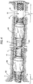
FIG. 4 is an enlarged view of a portion of the completion shown inFIG. 3 . - Referring to
FIG. 1 , a well completion in accordance with the prior art is illustrated that includes a verticalwell bore section 10 extending from the earth'ssurface 9 and containingproduction tubing 12 andcasing 14, with aproduction packer 16 that seals the annulus between the casing and tubing. It will be understood by one of ordinary skill in the art that the length of thevertical section 10 can be many thousands of meters. Thehorizontal section 20 of the open well bore is also of indeterminate length and is defined by the curvedtransitional heel portion 22 and the completion end, or toe, 24. Note that thecasing 14 terminates atregion 15 which defines the beginning of the open hole portion of the well. In the illustration ofFIG. 1 , the horizontal length of tubing is identified aselement 40 and is fitted with asingle ICD 48 in thetoe 24 of the open bore hole. - Also shown in
FIG. 1 is samplingpoint 80 located at the earth's surface that includescontrol valve 82 and suitable sampling, testing, recording andalarm apparatus 84. The use of five (5) open-hole packers, identified generally as 50, are shown secured tohorizontal production tubing 40 in accordance with methods and procedures known in the prior art. As noted above, the term "open-hole" refers to the fact that well casing 14 terminates at 15 and no well casingpipe 14 is installed in the horizontal section, as it is in the vertical portion of the well bore. In order to isolate the compartments between the packers, a fluid-tight seal with the rock surface must be formed. A section of tubing containing an ICD is referred to as a flowing compartment and a section containing blank or imperforated tubing as a non-flowing compartment. - As will be understood from the illustration of
FIG. 1 , the failure of any one of the open-hole packers will result in the passage of any reservoir fluids present in a non-flowing compartment into the compartment adjacent to the failed open-hole packer. In the prior art system illustrated byFIG. 1 , the detection of reservoir water with hydrocarbons sampled at thesurface sampling point 80 can be an indication that water is being drawn into the ICD directly from the reservoir with the hydrocarbons or that it is leaking into the flowing compartment from what was intended to be a non-flowing compartment. As noted in the discussion of the prior art, it is known to place a water-soluble tracer on the tubing in the toe end, but even that method is indefinite where the first open-hole packer 50A has failed and water is entering from the non-flowing compartment defined bypackers - The same procedures are followed to determine the seal effectiveness of one or more of the compartments in the advance well completion of
FIG. 2 in the event that one or more tracers are found by testing of the produced hydrocarbons and water at surface. - Referring now to
FIG. 2 , a pair of open-hole packers 50 are shown illustratively flanking a short section of blank production tubing, or pipe, 42 which is attached at one end to theinflow control device 48, which is typically a section of perforated tubing for admitting hydrocarbon fluids. The downstream end oftubing section 42 is joined to the remainder of theproduction tubing 12, which extends to the earth's surface at 9. In actual practice, the length of the blank pipe could be hundreds of feet (hundreds of meters) in length, and would be assembled from a number of shorter sections joined by couplings (not shown). - The method of the present invention can be utilized to reliably determine whether the packers are functioning as intended to isolate an ICD from flanking spaces through which pass sections of blank pipe. For example, if
packer 50A inFIG. 2 is providing an incomplete seal, water present in the non-flowing annular space "C" formed betweenpackers production zone 24 and be produced to the surface with the inflowing oil. - However, in accordance with the invention, the water-
soluble coating 60C onsection 42 passes intozone 24 and enters theICD 48 and eventually is detected at thesampling point 80 at the earth's surface. Since it is also common for water to be co-produced from the reservoir rock with the oil due to other local conditions, water produced at the surface that does not contain the tracer compound can be confirmed as co-produced water. It is important for the reservoir production manager to know whether water observed in tests of the produced fluids at thesurface sampling pant 80 is entering theproduction zone 24 with the oil from the adjacent reservoir rock or from an adjacent non-flowing compartment. If the water is leaking from an adjacent compartment, steps can be taken to rectify the situation and reduce the flow of water. - In a further embodiment of the method and system, a plurality of water-soluble and oil-soluble tracer compositions, e.g., 60A, 60B, etc., exhibiting distinctive characteristics can be applied to different compartmentalized sections of
tubing 42, and their respective locations maintained in a well log. In this way, the presence of one or more of the distinctive tracer compounds can be associated with one or more corresponding compartments. If produced water contains a tracer applied to the exterior surface of tubing or piping in a compartment that is remote from theICD 48, it can be concluded that one or more of the intermediate open-hole packers has failed. - For convenience, and the purposes of illustration, the water-soluble and oil-soluble coatings are shown in uniform stippling in the drawings. It will be understood that the coating compositions can be applied as separate bands or sections and cured as required by their respective properties.
- This aspect of the method can also include applying tracer-containing coatings to the exterior of the production sections between any of the plurality of open-hole packers so that any water or oil produced from the reservoir with the oil will solubilize and carry along its own distinctive tracer composition.
- Referring now to
FIG. 3 , there is schematically illustrated another preferred embodiment of the invention in whichadditional ICDs 48 are positioned along thehorizontal tubing string 40 in a series of spaced-apart hydrocarbon production zones. Theseinput control devices 48 are isolated by open-hole packers production packer 16, thereby formingproduction flowing compartments toe end 24 of the horizontal well bore whereICD 48 is located. The surfaces oftubing sections 42 in non-flowing compartments adjacent to the flowing compartments are coated with water-soluble and oil-soluble marker compositions, each of which have distinctive and distinguishable characteristics that can be individually identified at thesurface test station 84. - With continuing reference to the advance well completion of
FIG. 3 , the method of determining the seal effectiveness of one or more compartments in accordance with the method of the invention will be described. The method includes the steps of coating the exterior surface of the tubing in the non-flowing compartment A with water-soluble and oil-soluble tracers 60A; coating the exterior surface of the tubing in the non-flowing compartment B with water-soluble and oil-soluble tracers 60B; coating the exterior surface of the tubing in the non-flowing compartment C with water-soluble and oil-soluble tracers 60C, where tracers A, tracers B and tracers C are, respectively, three different water-soluble and oil-soluble tracers that can be readily be recognized and distinguished separately when produced at surface and subjected to testing of the type known to the art. - Assuming that the open-
hole packer 50A fails and 50B is holding,tracers 60C will be produced with the reservoir fluids entering theflowing compartment 3.Tracers 60C will be detected with the produced reservoir fluids at surface. As a result, it will be revealed that the non-flowing compartment C is not functioning. In this case, the flowingcompartment 4 and the non-flowing compartment C are considered as one compartment. However, the effect of the open-hole packer 50B will be negligible without the sealing of 50A. Therefore, flowingcompartment 4, non-flowing compartment C and theflowing compartment 3 are considered as one compartment. - Assuming that the open-
hole packer 50B fails and 50A is holding,tracers 60C will be produced with the reservoir fluids entering theflowing compartment 3.Tracers 60C will be detected with the produced reservoir fluids at surface. As a result, it will be determined by the test results of 84 that the non-flowing compartment C is not functioning. In this case, the flowingcompartment 3 and the non-flowing compartment C are considered as one compartment. However, the effect of the open-hole packer 50A will be negligible without the sealing of 50B. Therefore, flowingcompartment 4, non-flowing compartment C and theflowing compartment 3 are considered as one compartment. - The sampling station can also utilize appropriate software to accept predetermined minimum levels of tracer compounds, which corresponds to a determinable percent of water based on the flowrate of hydrocarbon fluid and water, without sounding an alarm. Thus, some predetermined volume of leakage of ground water will be tolerated, but when the detected concentration or level of the tracer compound(s) exceeds a predetermined value, the alarm is generated.
- In a further detailed illustration of the method and apparatus of the invention, and with reference to
FIG. 4 , the condition arises wherepackers toe end compartment 4 and flowingcompartment 3. The water and oil solubilizes coating 60C and both are produced the twoICDs 48 to surfacesampling station 80 with the hydrocarbon fluid. Referring to the well logs, the production manager readily determines the location and identification of the failed open-hole packers as 50B and 50A. - Similarly, if tracer compounds 60A and 60B were detected by the
sampling station 84, it would be concluded thatpackers ICD 48 with the hydrocarbon fluid(s) will not contain a tracer compound. - Similarly, if oil were to pass from a flowing compartment into an adjacent or more remote non-flowing compartment, the oil-soluble tracer(s) would be dissolved and be produced with the hydrocarbons at the surface. Since the location of each oil-soluble composition is known to the production manager, the location of the failed open-hole packers can also be identified. This type of operational information and control is not possible with the methods and assemblies of the prior art.
- From the above description, it will be understood that the present invention broadly comprehends the use of a tracer material to indicate whether one or more open-hole packers positioned in a horizontal oil well bore are functioning properly to isolate an adjacent production section fitted with an ICD by applying a coating containing a water-soluble composition to the exterior surfaces of the tubing.
- The invention has been described in detail above and illustrated in the attached drawings. Other embodiments and modifications will be apparent to those of ordinary skill in the art and the scope of the invention is to be determined by the claims that follow.
Claims (16)
- A method of determining the effectiveness of one or more compartmentalization seals in providing a water-tight barrier to isolate a hydrocarbon inflow control device (48), forming the terminus of a section of production tubing (12), said inflow control device being positioned within the toe end (24) of a subterranean generally horizontal open-hole well section (20) of reservoir rock, the production tubing (12) extending to the earth's surface, the method comprising:a. securing a first length of marker tubing (42), part of the production tubing (12), to the inflow control device (48), a portion of the outer surface of the marker tubing (42) being coated with water-soluble and oil-soluble tracer compositions (60C), each having a first set of known characteristics;b. securing a first open-hole packer (50A) about the outer surface of said first marker tubing (42), said packer extending radially outwardly from said outer surface to contact the surrounding reservoir wall to thereby create a flowing first compartment (4) containing said inflow control device at the toe end of the well and a non-flowing second compartment (C) containing the portion of said first length of marker tubing coated with tracer compositions (60C);c. extracting a hydrocarbon fluid stream from the reservoir rock through the inflow control device (48) and the production tubing (12) and producing the hydrocarbon fluid stream at the earth's surface; andd. testing the hydrocarbon stream at the earth's surface for the presence of said tracer compositions (60C) in order to determine the effectiveness of the compartmentalization of said open-hole well section (20) by the open-hole packer.
- The method according to claim 1, wherein the inflow control device (48) comprises a perforated pipe.
- The method according to claim 1, wherein the first length of marker tubing (42) has first and second ends, and wherein said inflow control device (48) is coupled to said first end, which further comprises:instead of coupling said second end to the production tubing (12) extending to the earth's surface,coupling a first end of a second length of tubing (12) to said second end, said second length of tubing (12) being located within said open-hole well section (20) and having a second end coupled to the production tubing (12) extending to the earth's surface; andsecuring a second open-hole packer (50B) about the outer surface of the second length of tubing (12) downstream of the first packer (50A), to thereby create a non-flowing thirdcompartment (B) containing said second length of tubing (12), said second length of tubing (12) being in fluid communication with the first length of marker tubing (42).
- The method according to claim 3, further comprising the step of applying a marker coating consisting of water-soluble tracer composition (60B) to a portion of the outer surface of said second length of tubing (12) which is located within the non-flowing third compartment (B).
- The method according to claim 4, further comprising the step of coating at least a portion of said second length of tubing (12) which is to be located within said third compartment (B) with a water-soluble tracer having a composition that is different from the water-soluble tracer on the outer surface of said first length of marker tubing (42).
- The method according to claim 1, wherein the first length of marker tubing (42) has first and second ends, and wherein said inflow control device (48) is coupled to said first end, further comprising the steps of:- instead of coupling said second end to the production tubing (12) extending to the earth's surface,
coupling a first end of a second inflow control device (48A) to said second end, said second inflow control device being located within said open-hole well section (20) and having a second end coupled to the production tubing (12) extending to the earth's surface; and- securing a second open-hole packer (50B) on the tubing (42) to create a flowing third compartment (B) containing said second inflow control device, wherein said second open-hole packer (50B) is positioned between said portion of the first length of marker tubing (42) being coated with said tracer compositions (60C) and said second inflow control device (48A). - The method according to claim 6, further comprising the steps of:
instead of coupling the second end of said second inflow control device (48A) to the production tubing (12) extending to the earth's surface,- coupling a first end of a second length of marker tubing (42) to the second end of said second inflow control device (48A), said second length of marker tubing (42) having a second end coupled to the production tubing (12) extending to the earth's surface, said second length of marker tubing (42) being located within said open-hole well section and having an outer surface; and- securing a third open-hole packer (50C) to the outer surface of said second length of tubing (42) to thereby create a non-flowing fourth compartment (B) containing said second length of tubing (42). - The method according to claim 7, further comprising the step of coating at least a portion of said second length of marker tubing (42) which is located in said non-flowing fourth compartment (B) with water-soluble and oil-soluble tracer compositions (60B) which preferably have characteristics that are detectably different from the tracer compositions (60C) on the outer surface of said first length of marker tubing (42).
- An assembly disposed in a hydrocarbon fluid producing well containing an open-hole well section (20) formed in reservoir rock and configured for determining, at the earth's surface, the effectiveness of one or more compartmentalization seals placed in the open-hole well section (20), wherein the open-hole well section is defined by a generally cylindrical wall having an at least generally horizontal axis, said assembly comprising:- a first inflow control device (48) disposed within the toe end (24) of said open-hole well section (20) for receiving an inflow of hydrocarbon fluid;- a first length of production tubing (42) coupled to said first inflow control device (48), wherein at least a portion of the outer surface of the first length of production tubing (42) is coated with water-soluble and oil-soluble tracer compositions (60c);- an open-hole packer (50A) disposed about the outer surface of said first length of tubing (42), said packer extending radially outwardly from said outer surface to contact said reservoir wall to thereby create a flowing first compartment (4) at the toe end (24) of the well containing said inflow control device (48) and a non-flowing second downstream compartment (C) containing at least the portion of said first length of production tubing (42) coated with said tracer compositions (60c);- a production tubing (12) coupled to the first length of production tubing (42) and extending to the earth's surface; and- testing means (84) in association with the producing tubing at the earth's surface for determining the presence of any tracer composition in the hydrocarbon fluid produced, whereby the effectiveness of the compartmentalization of said open-hole well section (20) by the open-hole packer (50A) can be determined.
- The assembly according to claim 9, wherein said inflow control device (48) comprises a perforated pipe.
- The assembly according to claim 9, wherein said first length of production tubing (42) has first and second ends, and wherein said first inflow control device (48) is coupled to said first end, and further comprising:- instead of said production tubing (12) extending to the earth's surface being coupled to the first length of production tubing (42),
a second section of blank tubing (12) disposed in said open-hole well section and having a first end coupled to said second end, said second section of blank tubing (12) having a second end coupled to said production tubing (12) extending to the earth's surface; and- a second open-hole packer (50B) disposed about the outer surface of said second section of blank tubing (12) to thereby create a non-flowing third compartment (B) containing said second section of blank tubing (12). - The assembly according to claim 11, wherein at least a portion of said second section of blank tubing (12) located in said third compartment (B) is coated with water-soluble and oil-soluble tracer compositions (60B) which are preferably different from the water-soluble and oil-soluble tracer compositions (60C) on the outer surface of said first length of production tubing (42).
- The assembly according to claim 9, wherein said first length of production tubing (42) has first and second ends, and wherein said first inflow control device (48) is coupled to said first end, further comprising:- instead of said production tubing (12) extending to the earth's surface being coupled to the first length of production tubing (42),- a second inflow control device (48A) disposed in said open-hole well section and coupled at a first end of said second inflow control device to the second end of the first length of production tubing (42), said second inflow control device having a second end coupled to said production tubing (12) extending to the earth's surface; and- a second open-hole packer (50B) disposed about said outer surface for creating a flowing third compartment (B) containing said second inflow control device (48A), wherein said second open-hole packer (50B) is positioned between said portion of the first length of production tubing (42) coated with said tracer compositions (60C) and second inflow control device (48A).
- The assembly according to claim 13, further comprising:- instead of said production tubing (12) extending to the earth's surface being coupled to the second end of said second inflow control device,- a second length of tubing (42)
disposed in said open-hole well section coupled at a first end of said second length of tubing (42) to the second end of the second inflow device (48A), said second length of tubing (42) having a second end coupled to said production tubing (12) extending to the earth's surface, the outer surface of said second length of tubing being coated with water-soluble and oil-soluble tracer compositions (60B); and- a third open hole packer (50C) disposed about the outer surface of said second length of tubing (42) section for creating a non-flowing fourth compartment (B) containing said second length of tubing (42), wherein said third open hole packer is positioned between said second inflow control device (48A) and said second length of tubing (42) coated with said tracer compositions (60B). - The assembly according to claim 14, wherein said first and second lengths of tubing (42) are coated with analytically distinguishable different tracer compositions (60C, 60B).
- An assembly disposed in a hydrocarbon fluid producing well containing an open-hole well section (20) formed in reservoir rock and configured for determining, at the earth's surface, the effectiveness of one or more compartmentalization seals placed in the open-hole well section (20), wherein the open-hole well section (20) is defined by a generally cylindrical wall having an at least generally horizontal axis, said assembly comprising:- a plurality of inflow control devices (48,48A) disposed within said open-hole well section at axially predetermined spaced apart locations and of which a first one (48) of the inflow control devices is positioned within the toe end (24) of the open hole well section (20),- the inflow control devices (48,48A) being joined in fluid communication by a section of blank production tubing (42), another section of blank production tubing (42) connected to and extending from the second inflow control device (48A) to connect to a production tubing (12) extending to the earth's surface for delivering fluids produced in the open-hole well section,- two open-hole packers (50A,50B) operatively secured to the section of blank tubing (42) between the inflow control devices (48,48A), one open hole packer (50C) operatively secured to the section of blank tubing (42) extending from the second inflow control device (48A) to connect to the production tubing (12), said open-hole packers extending radially outwardly to contact the open-hole wall to define flowing compartments (3,4) containing the inflow control devices and intermediate non-flowing compartments (C,B) comprising the blank tubing sections (42),- the outer surface of the sections of blank tubing (42) in each of the non-flowing compartments (C,B) being coated with water-soluble and oil-soluble tracer compositions (60C,60B), the tracer compositions in one of the non-flowing compartments (C,B) being analytically distinguishable under appropriate test conditions from the tracer compositions in the other non-flowing compartment,- testing means (84) in association with the producing tubing at the earth's surface for determining the presence of any tracer composition in the hydrocarbon fluid produced.
Applications Claiming Priority (2)
| Application Number | Priority Date | Filing Date | Title |
|---|---|---|---|
| US12/800,976 US8322414B2 (en) | 2010-05-25 | 2010-05-25 | Surface detection of failed open-hole packers using tubing with external tracer coatings |
| PCT/US2011/037685 WO2011149898A2 (en) | 2010-05-25 | 2011-05-24 | Surface detection of failed open-hole packers using tubing with external tracer coatings |
Publications (3)
| Publication Number | Publication Date |
|---|---|
| EP2576980A2 EP2576980A2 (en) | 2013-04-10 |
| EP2576980A4 EP2576980A4 (en) | 2013-12-04 |
| EP2576980B1 true EP2576980B1 (en) | 2018-10-24 |
Family
ID=45004700
Family Applications (1)
| Application Number | Title | Priority Date | Filing Date |
|---|---|---|---|
| EP11787222.6A Not-in-force EP2576980B1 (en) | 2010-05-25 | 2011-05-24 | Surface detection of failed open-hole packers using tubing with external tracer coatings |
Country Status (4)
| Country | Link |
|---|---|
| US (1) | US8322414B2 (en) |
| EP (1) | EP2576980B1 (en) |
| CN (1) | CN103003524B (en) |
| WO (1) | WO2011149898A2 (en) |
Families Citing this family (33)
| Publication number | Priority date | Publication date | Assignee | Title |
|---|---|---|---|---|
| US20120090835A1 (en) * | 2010-10-13 | 2012-04-19 | Slaheddine Kefi | Downhole material-delivery system for subterranean wells |
| US8833154B2 (en) * | 2010-10-19 | 2014-09-16 | Schlumberger Technology Corporation | Tracer identification of downhole tool actuation |
| US8668019B2 (en) * | 2010-12-29 | 2014-03-11 | Baker Hughes Incorporated | Dissolvable barrier for downhole use and method thereof |
| US8584756B1 (en) * | 2012-01-17 | 2013-11-19 | Halliburton Energy Sevices, Inc. | Methods of isolating annular areas formed by multiple casing strings in a well |
| EP2825728A2 (en) * | 2012-03-15 | 2015-01-21 | Chevron U.S.A. Inc. | Outward venting of inflow tracer in production wells |
| CN102650207A (en) * | 2012-05-09 | 2012-08-29 | 中国石油天然气股份有限公司 | Layered tracer monitoring method between wells |
| WO2014003775A1 (en) * | 2012-06-29 | 2014-01-03 | Halliburton Energy Services, Inc. | Isolation assembly for inflow control device |
| CN104121013B (en) * | 2013-04-25 | 2016-08-17 | 中国石油化工股份有限公司 | For the water detection device of horizontal well and use its method determining water exit position |
| CN104234638B (en) * | 2013-06-21 | 2017-10-17 | 中国石油天然气股份有限公司 | Mechanical water-seeking string and water-seeking method for multi-stage fracturing horizontal well with casing completion |
| US9416651B2 (en) | 2013-07-12 | 2016-08-16 | Saudi Arabian Oil Company | Surface confirmation for opening downhole ports using pockets for chemical tracer isolation |
| US10100632B2 (en) * | 2013-11-29 | 2018-10-16 | Resman As | Petroleum well formation back pressure field meter system |
| CN105672995B (en) * | 2013-12-13 | 2018-05-01 | 中国工程物理研究院核物理与化学研究所 | High water cut horizontal well outlet part Bit Parity element labeled test method |
| US10215018B2 (en) | 2014-01-07 | 2019-02-26 | Schlumberger Technology Corporation | Fluid tracer installation |
| US20150198038A1 (en) | 2014-01-15 | 2015-07-16 | Baker Hughes Incorporated | Methods and systems for monitoring well integrity and increasing the lifetime of a well in a subterranean formation |
| CN105019884A (en) * | 2014-04-25 | 2015-11-04 | 天津大港油田钻采技术开发公司 | Screen pipe horizontal well production profile testing apparatus and testing method for same |
| CA2954736C (en) * | 2014-08-20 | 2020-01-14 | Halliburton Energy Services, Inc. | Flow sensing in subterranean wells |
| WO2016028289A1 (en) * | 2014-08-20 | 2016-02-25 | Halliburton Energy Services, Inc. | Opto-acoustic flowmeter for use in subterranean wells |
| CN105986797B (en) * | 2015-02-13 | 2018-12-25 | 中国石油天然气股份有限公司 | Staged Fracturing Method for Horizontal Wells |
| CN106555569B (en) * | 2015-09-24 | 2021-04-27 | 中国石油化工股份有限公司 | Water control tool |
| US10677626B2 (en) * | 2016-03-01 | 2020-06-09 | Besst, Inc. | Flowmeter profiling system for use in groundwater production wells and boreholes |
| US10392935B2 (en) * | 2016-03-24 | 2019-08-27 | Expro North Sea Limited | Monitoring systems and methods |
| US10415382B2 (en) * | 2016-05-03 | 2019-09-17 | Schlumberger Technology Corporation | Method and system for establishing well performance during plug mill-out or cleanout/workover operations |
| US10613053B2 (en) | 2017-10-25 | 2020-04-07 | Saudi Arabian Oil Company | Electrophoresis analysis to identify tracers in produced water at a well head |
| NO343990B1 (en) * | 2017-12-28 | 2019-08-05 | Resman As | A method of multi-phase petroleum well characterization |
| CN111236905A (en) * | 2018-11-13 | 2020-06-05 | 中国石油化工股份有限公司 | Method for testing horizontal well output profile |
| CN110410062B (en) * | 2019-08-19 | 2022-01-28 | 西南石油大学 | Implementation method of real-time production monitoring-downhole control of thickened oil SAGD horizontal well |
| CN110566189A (en) * | 2019-09-27 | 2019-12-13 | 西安石油大学 | Slow-release tracer agent real-time water exploration device, horizontal well real-time water exploration and water shutoff integrated tubular column and implementation method |
| CN111810114B (en) * | 2020-06-04 | 2023-11-10 | 中海油田服务股份有限公司 | Tracing water-finding and sectional water-controlling system and method |
| CN114458284A (en) * | 2020-10-30 | 2022-05-10 | 中国石油天然气股份有限公司 | Release device, screen pipe column and production section testing method |
| US11913855B2 (en) | 2021-06-03 | 2024-02-27 | Caterpillar Inc. | Multi-layer hose with tracer material |
| US12320227B2 (en) | 2023-05-17 | 2025-06-03 | Saudi Arabian Oil Company | Monitoring integrity of downhole mechanical plug |
| CN119491716B (en) * | 2023-08-15 | 2026-04-28 | 中国石油天然气股份有限公司 | A delayed tracer capsule and its method of use |
| CN118088162B (en) * | 2023-12-29 | 2024-12-31 | 中国石油大学(华东) | A sandstone gas reservoir annulus leakage monitoring system |
Citations (1)
| Publication number | Priority date | Publication date | Assignee | Title |
|---|---|---|---|---|
| EP2372331A1 (en) * | 2010-03-31 | 2011-10-05 | PRAD Research and Development Limited | System and method for determining incursion of water in a well |
Family Cites Families (18)
| Publication number | Priority date | Publication date | Assignee | Title |
|---|---|---|---|---|
| US2618341A (en) * | 1947-05-23 | 1952-11-18 | Lane Wells Co | Well packer |
| US3848124A (en) | 1971-01-25 | 1974-11-12 | R Vann | Method and apparatus for determining communication of a perforated zone with a second zone |
| US4008763A (en) | 1976-05-20 | 1977-02-22 | Atlantic Richfield Company | Well treatment method |
| US5392850A (en) | 1994-01-27 | 1995-02-28 | Atlantic Richfield Company | System for isolating multiple gravel packed zones in wells |
| AU3277495A (en) * | 1995-07-25 | 1997-02-26 | Downhole Systems Technology Canada | Safeguarded method and apparatus for fluid communication usig coiled tubing, with application to drill stem testing |
| NO305181B1 (en) | 1996-06-28 | 1999-04-12 | Norsk Hydro As | Method for determining the inflow of oil and / or gas into a well |
| US6815303B2 (en) * | 1998-04-29 | 2004-11-09 | Micron Technology, Inc. | Bipolar transistors with low-resistance emitter contacts |
| US8682589B2 (en) | 1998-12-21 | 2014-03-25 | Baker Hughes Incorporated | Apparatus and method for managing supply of additive at wellsites |
| NO309884B1 (en) | 2000-04-26 | 2001-04-09 | Sinvent As | Reservoir monitoring using chemically intelligent release of tracers |
| AU2001294412A1 (en) | 2000-07-21 | 2002-02-05 | Sinvent A/S | Combined liner and matrix system, use of the system and method for control and monitoring of processes in a well |
| US6789621B2 (en) | 2000-08-03 | 2004-09-14 | Schlumberger Technology Corporation | Intelligent well system and method |
| US6564866B2 (en) | 2000-12-27 | 2003-05-20 | Baker Hughes Incorporated | Method and apparatus for a tubing conveyed perforating guns fire identification system using enhanced marker material |
| US6830104B2 (en) | 2001-08-14 | 2004-12-14 | Halliburton Energy Services, Inc. | Well shroud and sand control screen apparatus and completion method |
| US6896074B2 (en) | 2002-10-09 | 2005-05-24 | Schlumberger Technology Corporation | System and method for installation and use of devices in microboreholes |
| US7347260B2 (en) * | 2004-10-22 | 2008-03-25 | Core Laboratories Lp, A Delaware Limited Partnership | Method for determining tracer concentration in oil and gas production fluids |
| CN101529047A (en) * | 2006-10-24 | 2009-09-09 | 国际壳牌研究有限公司 | System for determining sealing in a wellbore |
| US7805248B2 (en) | 2007-04-19 | 2010-09-28 | Baker Hughes Incorporated | System and method for water breakthrough detection and intervention in a production well |
| US9091133B2 (en) | 2009-02-20 | 2015-07-28 | Halliburton Energy Services, Inc. | Swellable material activation and monitoring in a subterranean well |
-
2010
- 2010-05-25 US US12/800,976 patent/US8322414B2/en active Active - Reinstated
-
2011
- 2011-05-24 EP EP11787222.6A patent/EP2576980B1/en not_active Not-in-force
- 2011-05-24 CN CN201180033764.5A patent/CN103003524B/en not_active Expired - Fee Related
- 2011-05-24 WO PCT/US2011/037685 patent/WO2011149898A2/en not_active Ceased
Patent Citations (1)
| Publication number | Priority date | Publication date | Assignee | Title |
|---|---|---|---|---|
| EP2372331A1 (en) * | 2010-03-31 | 2011-10-05 | PRAD Research and Development Limited | System and method for determining incursion of water in a well |
Also Published As
| Publication number | Publication date |
|---|---|
| WO2011149898A2 (en) | 2011-12-01 |
| EP2576980A4 (en) | 2013-12-04 |
| EP2576980A2 (en) | 2013-04-10 |
| WO2011149898A3 (en) | 2012-06-14 |
| CN103003524A (en) | 2013-03-27 |
| US20110290480A1 (en) | 2011-12-01 |
| CN103003524B (en) | 2016-03-16 |
| US8322414B2 (en) | 2012-12-04 |
Similar Documents
| Publication | Publication Date | Title |
|---|---|---|
| US8322414B2 (en) | Surface detection of failed open-hole packers using tubing with external tracer coatings | |
| AU2012257565B2 (en) | Determining whether a wellbore sealing operation has been performed correctly | |
| US9725987B2 (en) | System and method for performing wellbore stimulation operations | |
| US20170138169A1 (en) | Monitoring diversion degradation in a well | |
| CA3024469A1 (en) | Method and system for performing hydrocarbon operations using communications associated with completions | |
| Cramer et al. | Pumpdown Diagnostics for Plug-and-Perf Treatments | |
| CN106062312A (en) | Method and apparatus for reservoir testing and monitoring | |
| WO2020076163A1 (en) | Plug and abandonment with overdisplaced cement | |
| Kent et al. | Intelligent completion inside uncemented liner for selective high-rate carbonate matrix acidizing | |
| Williams et al. | Wireless reservoir surveillance using intelligent tracers | |
| Nozaki et al. | Review and analysis of zonal-isolation effectiveness in carbonate reservoirs using multistage stimulation systems | |
| Anopov et al. | Permanent downhole chemical tracer system for wireless surveillance and optimizing well production | |
| John et al. | Integration of Distributed Temperature Sensing Technology with Open Hole Gravel Packed Completions-The ACG Field Experience | |
| Baihly* et al. | Fiber-optic revelations from a multistage openhole lateral fracturing treatment | |
| AU2021257378B2 (en) | Tool and method for verification of pressure integrity behind downhole casing | |
| Prosvirnov et al. | Dynamic reservoir characterization and production optimization by integrating intelligent inflow tracers and Pressure transient analysis in a long horizontal well for the Ekofisk field, Norwegian Continental Shelf | |
| Lotfy et al. | First Co-Implementation of Inflow and Inter-Well Tracers in Offshore Abu Dhabi: Towards Cost Efficient Reservoir Monitoring and Management | |
| Alshaer et al. | Advanced Multi-lateral Monitoring Using Intelligent Inflow Tracers With Production Log Comparison In A Carbonate Reservoir | |
| Al-Morakhi et al. | Real time advanced flow analysis for early kick/loss detection & identification of open fractures | |
| US12320227B2 (en) | Monitoring integrity of downhole mechanical plug | |
| US20170159424A1 (en) | Method and system delivering a tracer to a flow | |
| Williams et al. | Intelligent Inflow Tracers Obtain Information With Less Risk, Cost | |
| Galli et al. | From Leak Path Detection to Quantitative Flow Profiling: The Exciting Journey of the Noise | |
| Kent et al. | Intelligent completions and un-cemented liners combine to provide a fully completed solution with zonal isolation in Norway | |
| RU2800115C1 (en) | Method for determining tightness of packers |
Legal Events
| Date | Code | Title | Description |
|---|---|---|---|
| PUAI | Public reference made under article 153(3) epc to a published international application that has entered the european phase |
Free format text: ORIGINAL CODE: 0009012 |
|
| 17P | Request for examination filed |
Effective date: 20121221 |
|
| AK | Designated contracting states |
Kind code of ref document: A2 Designated state(s): AL AT BE BG CH CY CZ DE DK EE ES FI FR GB GR HR HU IE IS IT LI LT LU LV MC MK MT NL NO PL PT RO RS SE SI SK SM TR |
|
| DAX | Request for extension of the european patent (deleted) | ||
| A4 | Supplementary search report drawn up and despatched |
Effective date: 20131107 |
|
| RIC1 | Information provided on ipc code assigned before grant |
Ipc: E21B 47/10 20120101AFI20131031BHEP Ipc: E21B 33/124 20060101ALI20131031BHEP |
|
| 17Q | First examination report despatched |
Effective date: 20160707 |
|
| STAA | Information on the status of an ep patent application or granted ep patent |
Free format text: STATUS: EXAMINATION IS IN PROGRESS |
|
| GRAP | Despatch of communication of intention to grant a patent |
Free format text: ORIGINAL CODE: EPIDOSNIGR1 |
|
| STAA | Information on the status of an ep patent application or granted ep patent |
Free format text: STATUS: GRANT OF PATENT IS INTENDED |
|
| INTG | Intention to grant announced |
Effective date: 20180531 |
|
| GRAS | Grant fee paid |
Free format text: ORIGINAL CODE: EPIDOSNIGR3 |
|
| GRAA | (expected) grant |
Free format text: ORIGINAL CODE: 0009210 |
|
| STAA | Information on the status of an ep patent application or granted ep patent |
Free format text: STATUS: THE PATENT HAS BEEN GRANTED |
|
| AK | Designated contracting states |
Kind code of ref document: B1 Designated state(s): AL AT BE BG CH CY CZ DE DK EE ES FI FR GB GR HR HU IE IS IT LI LT LU LV MC MK MT NL NO PL PT RO RS SE SI SK SM TR |
|
| REG | Reference to a national code |
Ref country code: GB Ref legal event code: FG4D |
|
| REG | Reference to a national code |
Ref country code: CH Ref legal event code: EP |
|
| REG | Reference to a national code |
Ref country code: IE Ref legal event code: FG4D |
|
| REG | Reference to a national code |
Ref country code: AT Ref legal event code: REF Ref document number: 1056889 Country of ref document: AT Kind code of ref document: T Effective date: 20181115 |
|
| REG | Reference to a national code |
Ref country code: DE Ref legal event code: R096 Ref document number: 602011053240 Country of ref document: DE |
|
| REG | Reference to a national code |
Ref country code: NO Ref legal event code: T2 Effective date: 20181024 |
|
| REG | Reference to a national code |
Ref country code: NL Ref legal event code: MP Effective date: 20181024 |
|
| REG | Reference to a national code |
Ref country code: LT Ref legal event code: MG4D |
|
| REG | Reference to a national code |
Ref country code: AT Ref legal event code: MK05 Ref document number: 1056889 Country of ref document: AT Kind code of ref document: T Effective date: 20181024 |
|
| PG25 | Lapsed in a contracting state [announced via postgrant information from national office to epo] |
Ref country code: NL Free format text: LAPSE BECAUSE OF FAILURE TO SUBMIT A TRANSLATION OF THE DESCRIPTION OR TO PAY THE FEE WITHIN THE PRESCRIBED TIME-LIMIT Effective date: 20181024 |
|
| PG25 | Lapsed in a contracting state [announced via postgrant information from national office to epo] |
Ref country code: BG Free format text: LAPSE BECAUSE OF FAILURE TO SUBMIT A TRANSLATION OF THE DESCRIPTION OR TO PAY THE FEE WITHIN THE PRESCRIBED TIME-LIMIT Effective date: 20190124 Ref country code: PL Free format text: LAPSE BECAUSE OF FAILURE TO SUBMIT A TRANSLATION OF THE DESCRIPTION OR TO PAY THE FEE WITHIN THE PRESCRIBED TIME-LIMIT Effective date: 20181024 Ref country code: IS Free format text: LAPSE BECAUSE OF FAILURE TO SUBMIT A TRANSLATION OF THE DESCRIPTION OR TO PAY THE FEE WITHIN THE PRESCRIBED TIME-LIMIT Effective date: 20190224 Ref country code: HR Free format text: LAPSE BECAUSE OF FAILURE TO SUBMIT A TRANSLATION OF THE DESCRIPTION OR TO PAY THE FEE WITHIN THE PRESCRIBED TIME-LIMIT Effective date: 20181024 Ref country code: AT Free format text: LAPSE BECAUSE OF FAILURE TO SUBMIT A TRANSLATION OF THE DESCRIPTION OR TO PAY THE FEE WITHIN THE PRESCRIBED TIME-LIMIT Effective date: 20181024 Ref country code: LV Free format text: LAPSE BECAUSE OF FAILURE TO SUBMIT A TRANSLATION OF THE DESCRIPTION OR TO PAY THE FEE WITHIN THE PRESCRIBED TIME-LIMIT Effective date: 20181024 Ref country code: FI Free format text: LAPSE BECAUSE OF FAILURE TO SUBMIT A TRANSLATION OF THE DESCRIPTION OR TO PAY THE FEE WITHIN THE PRESCRIBED TIME-LIMIT Effective date: 20181024 Ref country code: LT Free format text: LAPSE BECAUSE OF FAILURE TO SUBMIT A TRANSLATION OF THE DESCRIPTION OR TO PAY THE FEE WITHIN THE PRESCRIBED TIME-LIMIT Effective date: 20181024 Ref country code: ES Free format text: LAPSE BECAUSE OF FAILURE TO SUBMIT A TRANSLATION OF THE DESCRIPTION OR TO PAY THE FEE WITHIN THE PRESCRIBED TIME-LIMIT Effective date: 20181024 |
|
| PG25 | Lapsed in a contracting state [announced via postgrant information from national office to epo] |
Ref country code: PT Free format text: LAPSE BECAUSE OF FAILURE TO SUBMIT A TRANSLATION OF THE DESCRIPTION OR TO PAY THE FEE WITHIN THE PRESCRIBED TIME-LIMIT Effective date: 20190224 Ref country code: SE Free format text: LAPSE BECAUSE OF FAILURE TO SUBMIT A TRANSLATION OF THE DESCRIPTION OR TO PAY THE FEE WITHIN THE PRESCRIBED TIME-LIMIT Effective date: 20181024 Ref country code: GR Free format text: LAPSE BECAUSE OF FAILURE TO SUBMIT A TRANSLATION OF THE DESCRIPTION OR TO PAY THE FEE WITHIN THE PRESCRIBED TIME-LIMIT Effective date: 20190125 Ref country code: AL Free format text: LAPSE BECAUSE OF FAILURE TO SUBMIT A TRANSLATION OF THE DESCRIPTION OR TO PAY THE FEE WITHIN THE PRESCRIBED TIME-LIMIT Effective date: 20181024 Ref country code: RS Free format text: LAPSE BECAUSE OF FAILURE TO SUBMIT A TRANSLATION OF THE DESCRIPTION OR TO PAY THE FEE WITHIN THE PRESCRIBED TIME-LIMIT Effective date: 20181024 |
|
| REG | Reference to a national code |
Ref country code: DE Ref legal event code: R097 Ref document number: 602011053240 Country of ref document: DE |
|
| PG25 | Lapsed in a contracting state [announced via postgrant information from national office to epo] |
Ref country code: CZ Free format text: LAPSE BECAUSE OF FAILURE TO SUBMIT A TRANSLATION OF THE DESCRIPTION OR TO PAY THE FEE WITHIN THE PRESCRIBED TIME-LIMIT Effective date: 20181024 Ref country code: DK Free format text: LAPSE BECAUSE OF FAILURE TO SUBMIT A TRANSLATION OF THE DESCRIPTION OR TO PAY THE FEE WITHIN THE PRESCRIBED TIME-LIMIT Effective date: 20181024 Ref country code: IT Free format text: LAPSE BECAUSE OF FAILURE TO SUBMIT A TRANSLATION OF THE DESCRIPTION OR TO PAY THE FEE WITHIN THE PRESCRIBED TIME-LIMIT Effective date: 20181024 |
|
| PG25 | Lapsed in a contracting state [announced via postgrant information from national office to epo] |
Ref country code: EE Free format text: LAPSE BECAUSE OF FAILURE TO SUBMIT A TRANSLATION OF THE DESCRIPTION OR TO PAY THE FEE WITHIN THE PRESCRIBED TIME-LIMIT Effective date: 20181024 Ref country code: SM Free format text: LAPSE BECAUSE OF FAILURE TO SUBMIT A TRANSLATION OF THE DESCRIPTION OR TO PAY THE FEE WITHIN THE PRESCRIBED TIME-LIMIT Effective date: 20181024 Ref country code: RO Free format text: LAPSE BECAUSE OF FAILURE TO SUBMIT A TRANSLATION OF THE DESCRIPTION OR TO PAY THE FEE WITHIN THE PRESCRIBED TIME-LIMIT Effective date: 20181024 Ref country code: SK Free format text: LAPSE BECAUSE OF FAILURE TO SUBMIT A TRANSLATION OF THE DESCRIPTION OR TO PAY THE FEE WITHIN THE PRESCRIBED TIME-LIMIT Effective date: 20181024 |
|
| PLBE | No opposition filed within time limit |
Free format text: ORIGINAL CODE: 0009261 |
|
| STAA | Information on the status of an ep patent application or granted ep patent |
Free format text: STATUS: NO OPPOSITION FILED WITHIN TIME LIMIT |
|
| 26N | No opposition filed |
Effective date: 20190725 |
|
| PG25 | Lapsed in a contracting state [announced via postgrant information from national office to epo] |
Ref country code: SI Free format text: LAPSE BECAUSE OF FAILURE TO SUBMIT A TRANSLATION OF THE DESCRIPTION OR TO PAY THE FEE WITHIN THE PRESCRIBED TIME-LIMIT Effective date: 20181024 |
|
| REG | Reference to a national code |
Ref country code: DE Ref legal event code: R119 Ref document number: 602011053240 Country of ref document: DE |
|
| REG | Reference to a national code |
Ref country code: CH Ref legal event code: PL |
|
| GBPC | Gb: european patent ceased through non-payment of renewal fee |
Effective date: 20190524 |
|
| PG25 | Lapsed in a contracting state [announced via postgrant information from national office to epo] |
Ref country code: LI Free format text: LAPSE BECAUSE OF NON-PAYMENT OF DUE FEES Effective date: 20190531 Ref country code: CH Free format text: LAPSE BECAUSE OF NON-PAYMENT OF DUE FEES Effective date: 20190531 Ref country code: MC Free format text: LAPSE BECAUSE OF FAILURE TO SUBMIT A TRANSLATION OF THE DESCRIPTION OR TO PAY THE FEE WITHIN THE PRESCRIBED TIME-LIMIT Effective date: 20181024 |
|
| REG | Reference to a national code |
Ref country code: BE Ref legal event code: MM Effective date: 20190531 |
|
| PG25 | Lapsed in a contracting state [announced via postgrant information from national office to epo] |
Ref country code: LU Free format text: LAPSE BECAUSE OF NON-PAYMENT OF DUE FEES Effective date: 20190524 |
|
| PG25 | Lapsed in a contracting state [announced via postgrant information from national office to epo] |
Ref country code: TR Free format text: LAPSE BECAUSE OF FAILURE TO SUBMIT A TRANSLATION OF THE DESCRIPTION OR TO PAY THE FEE WITHIN THE PRESCRIBED TIME-LIMIT Effective date: 20181024 |
|
| PG25 | Lapsed in a contracting state [announced via postgrant information from national office to epo] |
Ref country code: GB Free format text: LAPSE BECAUSE OF NON-PAYMENT OF DUE FEES Effective date: 20190524 Ref country code: DE Free format text: LAPSE BECAUSE OF NON-PAYMENT OF DUE FEES Effective date: 20191203 Ref country code: IE Free format text: LAPSE BECAUSE OF NON-PAYMENT OF DUE FEES Effective date: 20190524 |
|
| PG25 | Lapsed in a contracting state [announced via postgrant information from national office to epo] |
Ref country code: BE Free format text: LAPSE BECAUSE OF NON-PAYMENT OF DUE FEES Effective date: 20190531 |
|
| PG25 | Lapsed in a contracting state [announced via postgrant information from national office to epo] |
Ref country code: FR Free format text: LAPSE BECAUSE OF NON-PAYMENT OF DUE FEES Effective date: 20190531 |
|
| PG25 | Lapsed in a contracting state [announced via postgrant information from national office to epo] |
Ref country code: CY Free format text: LAPSE BECAUSE OF FAILURE TO SUBMIT A TRANSLATION OF THE DESCRIPTION OR TO PAY THE FEE WITHIN THE PRESCRIBED TIME-LIMIT Effective date: 20181024 |
|
| PG25 | Lapsed in a contracting state [announced via postgrant information from national office to epo] |
Ref country code: MT Free format text: LAPSE BECAUSE OF FAILURE TO SUBMIT A TRANSLATION OF THE DESCRIPTION OR TO PAY THE FEE WITHIN THE PRESCRIBED TIME-LIMIT Effective date: 20181024 Ref country code: HU Free format text: LAPSE BECAUSE OF FAILURE TO SUBMIT A TRANSLATION OF THE DESCRIPTION OR TO PAY THE FEE WITHIN THE PRESCRIBED TIME-LIMIT; INVALID AB INITIO Effective date: 20110524 |
|
| PG25 | Lapsed in a contracting state [announced via postgrant information from national office to epo] |
Ref country code: MK Free format text: LAPSE BECAUSE OF FAILURE TO SUBMIT A TRANSLATION OF THE DESCRIPTION OR TO PAY THE FEE WITHIN THE PRESCRIBED TIME-LIMIT Effective date: 20181024 |
|
| PGFP | Annual fee paid to national office [announced via postgrant information from national office to epo] |
Ref country code: NO Payment date: 20220506 Year of fee payment: 12 |
|
| P01 | Opt-out of the competence of the unified patent court (upc) registered |
Effective date: 20230529 |
|
| REG | Reference to a national code |
Ref country code: NO Ref legal event code: MMEP |
|
| PG25 | Lapsed in a contracting state [announced via postgrant information from national office to epo] |
Ref country code: NO Free format text: LAPSE BECAUSE OF NON-PAYMENT OF DUE FEES Effective date: 20230531 |