EP2575705B1 - Filter with an extension element - Google Patents
Filter with an extension element Download PDFInfo
- Publication number
- EP2575705B1 EP2575705B1 EP11726326.9A EP11726326A EP2575705B1 EP 2575705 B1 EP2575705 B1 EP 2575705B1 EP 11726326 A EP11726326 A EP 11726326A EP 2575705 B1 EP2575705 B1 EP 2575705B1
- Authority
- EP
- European Patent Office
- Prior art keywords
- gas
- ostomy bag
- extension element
- deodorising
- extension
- Prior art date
- Legal status (The legal status is an assumption and is not a legal conclusion. Google has not performed a legal analysis and makes no representation as to the accuracy of the status listed.)
- Active
Links
Images

Classifications
-
- A—HUMAN NECESSITIES
- A61—MEDICAL OR VETERINARY SCIENCE; HYGIENE
- A61F—FILTERS IMPLANTABLE INTO BLOOD VESSELS; PROSTHESES; DEVICES PROVIDING PATENCY TO, OR PREVENTING COLLAPSING OF, TUBULAR STRUCTURES OF THE BODY, e.g. STENTS; ORTHOPAEDIC, NURSING OR CONTRACEPTIVE DEVICES; FOMENTATION; TREATMENT OR PROTECTION OF EYES OR EARS; BANDAGES, DRESSINGS OR ABSORBENT PADS; FIRST-AID KITS
- A61F5/00—Orthopaedic methods or devices for non-surgical treatment of bones or joints; Nursing devices ; Anti-rape devices
- A61F5/44—Devices worn by the patient for reception of urine, faeces, catamenial or other discharge; Colostomy devices
- A61F5/441—Devices worn by the patient for reception of urine, faeces, catamenial or other discharge; Colostomy devices having venting or deodorant means, e.g. filters ; having antiseptic means, e.g. bacterial barriers
-
- A—HUMAN NECESSITIES
- A61—MEDICAL OR VETERINARY SCIENCE; HYGIENE
- A61F—FILTERS IMPLANTABLE INTO BLOOD VESSELS; PROSTHESES; DEVICES PROVIDING PATENCY TO, OR PREVENTING COLLAPSING OF, TUBULAR STRUCTURES OF THE BODY, e.g. STENTS; ORTHOPAEDIC, NURSING OR CONTRACEPTIVE DEVICES; FOMENTATION; TREATMENT OR PROTECTION OF EYES OR EARS; BANDAGES, DRESSINGS OR ABSORBENT PADS; FIRST-AID KITS
- A61F5/00—Orthopaedic methods or devices for non-surgical treatment of bones or joints; Nursing devices ; Anti-rape devices
- A61F5/44—Devices worn by the patient for reception of urine, faeces, catamenial or other discharge; Colostomy devices
- A61F5/4404—Details or parts
-
- A—HUMAN NECESSITIES
- A61—MEDICAL OR VETERINARY SCIENCE; HYGIENE
- A61F—FILTERS IMPLANTABLE INTO BLOOD VESSELS; PROSTHESES; DEVICES PROVIDING PATENCY TO, OR PREVENTING COLLAPSING OF, TUBULAR STRUCTURES OF THE BODY, e.g. STENTS; ORTHOPAEDIC, NURSING OR CONTRACEPTIVE DEVICES; FOMENTATION; TREATMENT OR PROTECTION OF EYES OR EARS; BANDAGES, DRESSINGS OR ABSORBENT PADS; FIRST-AID KITS
- A61F5/00—Orthopaedic methods or devices for non-surgical treatment of bones or joints; Nursing devices ; Anti-rape devices
- A61F5/44—Devices worn by the patient for reception of urine, faeces, catamenial or other discharge; Colostomy devices
- A61F5/445—Colostomy, ileostomy or urethrostomy devices
Definitions
- the invention relates to an ostomy bag according to the preamble of claim 1.
- Such an ostomy bag is known from WO-A-03/020188 .
- the filter has an extension element so that the inlet is placed a distance from the deodorising element.
- the discharge of flatus may exceed the discharge of solid and liquid faecal matter by many hundreds of percent and therefore there is usually the need for the continuous or frequent venting of the intestine or the collecting bag.
- the outflowing flatus is deodorised with a suitable filter.
- the active filter is powdered active carbon, which absorbs H 2 S being the principal component of the smell of flatus.
- the output from a colostomy or an ileostomy may stick on the face of the filter facing inwards in the collecting bag. This will eventually lead to clogging of the filter thereby reducing the flow through the filter.
- the filter When the filter is completely blocked, it will stop functioning and the bag will fill with gases and expand, an effect also known as ballooning. This may cause embarrassment for the user because the bag will be noticeable under the clothing. It may also lead to the bag being detached from the wafer, in case a two-piece appliance is used, or being detached from the skin, in case a one-piece appliance is used.
- International application no. WO2006/048019 relates to an in situ cleanable filter for an ostomy appliance comprising a pathway for leading gases to a vent in an ostomy bag and a protective element contained in said pathway to prevent solid or semi-liquid waste from blocking the pathway.
- the protective element is made of an open celled compressible material having a memory and having a pore size of at least 60 PPI.
- European Patent no. EP0607028B relates to an ostomy bag including a multi-stage filter system that provides contamination protection for a deodorizing filter in the system.
- the multi-stage filter system also includes a gas transmissible protection filter that is impassable to semi-liquid waste material.
- the protection filter is located in the ostomy bag to precede the deodorizing filter such that gaseous waste must pass through the protection filter before it passes through the deodorizing filter.
- German utility model no. DE20021420U relates to an ostomy bag with an inlet, a gas discharge opening where the gas discharge opening is placed upstream of the filter.
- the filter consists of a rod-shaped hollow body filled with a filtering medium.
- the invention relates to an ostomy bag with a filter construction.
- the ostomy bag has a front wall and a rear wall.
- the filter construction has a deodorising element and an extension element.
- the extension element has a gas-inlet portion which is provided with numerous gas-inlets placed across an outer surface of the extension element. Thereby it is ensured that at least one of the gas-inlets is always out of contact with the output.
- the invention relates to an ostomy bag comprising
- the extension element in the filter construction provides gas-inlets away from the deodorising element.
- the extension element may function as a kind of pre-filter, making the liquid and semi-solid matter travel a longer distance before potentially reaching the deodorising element.
- An ostomy bag is well-known in the art. It usually comprises a front wall and a rear wall of gas- and liquid impermeable foil-material (for example of polyethylene (PE), polyvinylchloride (PVC) or ethylene-vinyl-acetate (EVA)) that is welded or glued around the edges or the rim so as to form a waste collection chamber.
- the bag may be welded or glued only partly around the rim so that an opening for emptying the bag is provided in the lower end. In that case the bag may be provided with means for closing that opening.
- the bag includes a waste inlet opening which at the outer side is provided either with mechanical or adhesive coupling means for coupling to a body side wafer or with a skin-friendly adhesive adapted for direct adhering to the abdomen of the user.
- the waste inlet opening is placed in the upper part of the ostomy bag so that when a user stands up, the waste inlet opening will be above the midline of the ostomy bag. This leaves a larger collecting volume below the waste inlet opening.
- the top of the ostomy bag is defined as the part closest to the waste inlet opening, and the bottom is defined as the opposite part.
- the vent of the ostomy bag may be placed either in the contour or the rim of the bag - by leaving a small part of this un-welded, or it may be placed as a separate hole in the front or rear wall of the bag.
- the extension element is attached to the deodorising element. It provides an enclosure for the gas-flow which may be in the form of a tube element so as to allow for gas-flow through the tube from the gas-inlet portion including the gas-inlets to the deodorising element. It is an elongated element having a first end connected to the deodorising element and a second end opposite in the longitudinal direction. The gas-inlets being placed facing in opposite directions has the effect that no matter how the extension element is positioned, at least one of the gas-inlets is always accessible for entry of gas.
- the extension element includes buoyancy means. In this embodiment, the extension element is only attached to any part of the ostomy bag in the first end, where it is attached to the deodorising element.
- the extension element may float around freely in the bag. Because the extension element is made of material having a lower density than the output, the extension element will float atop the output.
- the theory is that with output from an ileostomy (which usually is rather thin, having a syrupy consistency) at least a part of the extension element will float "on top" of the output. With output from a colostomy (which usually is thicker, like porridge) the element will simply be pushed away.
- the extension element will thus never be covered completely by output and at least part of the gas-inlet portion is not covered in output for example the part facing upwards from the output, if the extension element floats atop the output. Therefore, at least some of the gas-inlets will never be completely covered and prevent the filter construction from being completely clogged and thus allow gas flow.
- the extension element may include buoyancy means in form of a foil-element or an element made of non-woven material.
- the foil-material may be the type of foil-material regularly used for filters for ostomy bags, for example styrene-ethylene-butadiene-styrene (SEBS) and a mixture of poly-ethylene (PE) and ethylene-vinyl-acetate (EVA).
- SEBS styrene-ethylene-butadiene-styrene
- PE poly-ethylene
- EVA ethylene-vinyl-acetate
- Non-woven materials may be of the type regularly used for covering the surface of the ostomy bag on the outside, for example poly-ethylene (PE), poly-propylene (PP) or Polyester. All of these types of material are cheap and cooperate well with the other materials in an ostomy bag.
- the extension element may be made by two elongate foil-elements welded together at their sides (and at the second end) so as to provide an enclosure between them. It may also be made by one foil-element folded upon itself and welded at the side and at the second end so as to provide an enclosure. It may be folded to provide an edge or folded to provide a tube-element.
- air enclosed in the foil-element may function as buoyancy means.
- foam material may be enclosed in the foil-element or the non-woven element.
- the foil-element or non-woven element is prevented from collapsing completely if it is bent due to the user's body movement.
- the foam may function as a further pre-filtering mechanism as it is able to capture liquid and semi-solid material entering into the extension element.
- the density of the extension element when compared to the density of the output in which the extension element is to be present.
- the density of most plastics is below 1000 kg/m 3 .
- the density of SEBS-foil is approximately 900 kg/m 3 .
- the plastics may in use enclose air, thus lowering the density of the extension element.
- the density of the foam material may be as low as 20 kg/m 3 .
- the buoyancy means is a buoyant element that is attached at the second end.
- This buoyant element may include a foam element enclosed in foil material.
- the extension element itself may be made of any material, because the buoyancy will be provided by a separate element.
- the buoyant element has to be able to provide enough buoyant force to keep the gas-inlet portion of the extension element afloat.
- the buoyancy force required depends on how much the bag is tilted around and squeezed during wear. It is contemplated that a buoyancy force of about 0.01 N will be enough in most situations. Tests have shown that a foam material of polyurethane (PU) with 45 PPI will provide enough buoyancy force if the foam is larger than 5 mm x 10 mm x 10 mm.
- PPI is a unit giving a measure for the pore size although it actually refers to number of pores per inch in the foam material.
- the length of the extension element influences how the element can be pushed away by or is able to float atop the output.
- the distance between the first end of the extension element and the end of the gas-inlet portion closest to the first end has to be so long that the gas-inlets can be kept open, even if the output gets very close to the deodorising element.
- the second end of the extension element is attached to the ostomy bag at a distance from the deodorising element. Attaching the extension element at a certain distance from the deodorising element allows a controlled distance between the gas-inlet portion of the extension and the deodorising element and thus a controlled distance between the gas-inlets and the deodorising element.
- the user typically adapts the wafer to the size and shape of the stoma.
- the second end of the extension element is attached so that the extension element is positioned distant from the waste inlet opening in a plane transverse to the walls of the ostomy bag.
- the entire filter construction may be positioned away from the volume of the bag immediately surrounding the waste inlet opening. This way the risk of cutting into the filter construction when cutting the wafer is minimised.
- the extension element may be kept within 2-5 cm from the rim of the pouch.
- the filter construction may have a rather sharp edge in some embodiments, for example where two foils are welded together to form the extension element. It may be an advantage if this edge is kept at least a few millimetres radially beyond the maximum cutting diameter of the waste inlet opening. This is to minimise the risk of the sharp edge irritation the stoma if the stoma were to enter into the ostomy bag.
Landscapes
- Health & Medical Sciences (AREA)
- Epidemiology (AREA)
- Nursing (AREA)
- Orthopedic Medicine & Surgery (AREA)
- Engineering & Computer Science (AREA)
- Biomedical Technology (AREA)
- Heart & Thoracic Surgery (AREA)
- Vascular Medicine (AREA)
- Life Sciences & Earth Sciences (AREA)
- Animal Behavior & Ethology (AREA)
- General Health & Medical Sciences (AREA)
- Public Health (AREA)
- Veterinary Medicine (AREA)
- Orthopedics, Nursing, And Contraception (AREA)
Description
- The invention relates to an ostomy bag according to the preamble of
claim 1. Such an ostomy bag is known fromWO-A-03/020188 - In connection with surgery for a number of diseases in the gastro-intestinal tract, one of the consequences in many cases is that the patient is left with an abdominal stoma such as a colostomy, an ileostomy or a urostomy in the abdominal wall for the discharge of visceral contents. The discharge of visceral contents including intestinal gases cannot be regulated at will. For that purpose, the user will have to rely on an appliance to collect the material emerging from such opening in a bag, which is later emptied and/or discarded at a suitable time.
- The discharge of flatus, measured in volume, may exceed the discharge of solid and liquid faecal matter by many hundreds of percent and therefore there is usually the need for the continuous or frequent venting of the intestine or the collecting bag. Normally the outflowing flatus is deodorised with a suitable filter. Commonly, the active filter is powdered active carbon, which absorbs H2S being the principal component of the smell of flatus.
- During use of a collecting bag, the output from a colostomy or an ileostomy may stick on the face of the filter facing inwards in the collecting bag. This will eventually lead to clogging of the filter thereby reducing the flow through the filter. When the filter is completely blocked, it will stop functioning and the bag will fill with gases and expand, an effect also known as ballooning. This may cause embarrassment for the user because the bag will be noticeable under the clothing. It may also lead to the bag being detached from the wafer, in case a two-piece appliance is used, or being detached from the skin, in case a one-piece appliance is used.
- International application no.
WO2006/048019 relates to an in situ cleanable filter for an ostomy appliance comprising a pathway for leading gases to a vent in an ostomy bag and a protective element contained in said pathway to prevent solid or semi-liquid waste from blocking the pathway. The protective element is made of an open celled compressible material having a memory and having a pore size of at least 60 PPI. - European Patent no.
EP0607028B relates to an ostomy bag including a multi-stage filter system that provides contamination protection for a deodorizing filter in the system. The multi-stage filter system also includes a gas transmissible protection filter that is impassable to semi-liquid waste material. The protection filter is located in the ostomy bag to precede the deodorizing filter such that gaseous waste must pass through the protection filter before it passes through the deodorizing filter. - German utility model no.
DE20021420U relates to an ostomy bag with an inlet, a gas discharge opening where the gas discharge opening is placed upstream of the filter. The filter consists of a rod-shaped hollow body filled with a filtering medium. - The invention relates to an ostomy bag with a filter construction. The ostomy bag has a front wall and a rear wall. The filter construction has a deodorising element and an extension element. The extension element has a gas-inlet portion which is provided with numerous gas-inlets placed across an outer surface of the extension element. Thereby it is ensured that at least one of the gas-inlets is always out of contact with the output.
- In a first aspect, the invention relates to an ostomy bag comprising
- a pouch including a front wall and a rear wall
- a waste inlet opening in the rear wall for letting the output from the stoma enter into the pouch,
- a vent opening in either the front wall or the rear wall for letting gas exit the bag,
- a filter construction with a gas-outlet in alignment with the vent opening,
- the filter construction including a deodorising element and an elongated extension element providing an enclosure for gas-flow,
- the deodorising element being provided with the gas outlet,
- the deodorising element being connected to a first end of the elongated extension element, the extension element being provided with a second end so that the direction from the first end to the second end defines the longitudinal direction of the extension element,
- the extension element having a gas-inlet portion including a number of gas-inlets to the filter construction,
- the gas-inlets being placed across an outer surface of the extension element in the transverse direction so that the gas-inlets generally face in the opposite directions from the outer surface.
- The extension element in the filter construction provides gas-inlets away from the deodorising element. Thus there is a distance between the closest gas-inlet and the deodorising element. Therefore, the extension element may function as a kind of pre-filter, making the liquid and semi-solid matter travel a longer distance before potentially reaching the deodorising element.
- An ostomy bag is well-known in the art. It usually comprises a front wall and a rear wall of gas- and liquid impermeable foil-material (for example of polyethylene (PE), polyvinylchloride (PVC) or ethylene-vinyl-acetate (EVA)) that is welded or glued around the edges or the rim so as to form a waste collection chamber. The bag may be welded or glued only partly around the rim so that an opening for emptying the bag is provided in the lower end. In that case the bag may be provided with means for closing that opening. The bag includes a waste inlet opening which at the outer side is provided either with mechanical or adhesive coupling means for coupling to a body side wafer or with a skin-friendly adhesive adapted for direct adhering to the abdomen of the user.
- Usually, the waste inlet opening is placed in the upper part of the ostomy bag so that when a user stands up, the waste inlet opening will be above the midline of the ostomy bag. This leaves a larger collecting volume below the waste inlet opening. Thus the top of the ostomy bag is defined as the part closest to the waste inlet opening, and the bottom is defined as the opposite part.
- The vent of the ostomy bag may be placed either in the contour or the rim of the bag - by leaving a small part of this un-welded, or it may be placed as a separate hole in the front or rear wall of the bag.
- The extension element is attached to the deodorising element. It provides an enclosure for the gas-flow which may be in the form of a tube element so as to allow for gas-flow through the tube from the gas-inlet portion including the gas-inlets to the deodorising element. It is an elongated element having a first end connected to the deodorising element and a second end opposite in the longitudinal direction. The gas-inlets being placed facing in opposite directions has the effect that no matter how the extension element is positioned, at least one of the gas-inlets is always accessible for entry of gas. In an embodiment of the invention, the extension element includes buoyancy means. In this embodiment, the extension element is only attached to any part of the ostomy bag in the first end, where it is attached to the deodorising element. Therefore, the remaining part of the extension element may float around freely in the bag. Because the extension element is made of material having a lower density than the output, the extension element will float atop the output. The theory is that with output from an ileostomy (which usually is rather thin, having a syrupy consistency) at least a part of the extension element will float "on top" of the output. With output from a colostomy (which usually is thicker, like porridge) the element will simply be pushed away. The extension element will thus never be covered completely by output and at least part of the gas-inlet portion is not covered in output for example the part facing upwards from the output, if the extension element floats atop the output. Therefore, at least some of the gas-inlets will never be completely covered and prevent the filter construction from being completely clogged and thus allow gas flow.
- The extension element may include buoyancy means in form of a foil-element or an element made of non-woven material. The foil-material may be the type of foil-material regularly used for filters for ostomy bags, for example styrene-ethylene-butadiene-styrene (SEBS) and a mixture of poly-ethylene (PE) and ethylene-vinyl-acetate (EVA). Non-woven materials may be of the type regularly used for covering the surface of the ostomy bag on the outside, for example poly-ethylene (PE), poly-propylene (PP) or Polyester. All of these types of material are cheap and cooperate well with the other materials in an ostomy bag.
- The extension element may be made by two elongate foil-elements welded together at their sides (and at the second end) so as to provide an enclosure between them. It may also be made by one foil-element folded upon itself and welded at the side and at the second end so as to provide an enclosure. It may be folded to provide an edge or folded to provide a tube-element.
- In the above-mentioned embodiments, air enclosed in the foil-element may function as buoyancy means.
- In an embodiment, foam material may be enclosed in the foil-element or the non-woven element. Thereby the foil-element or non-woven element is prevented from collapsing completely if it is bent due to the user's body movement. Thus, there will always be pathway through the extension element for the gas flow towards the deodorising element. The foam may function as a further pre-filtering mechanism as it is able to capture liquid and semi-solid material entering into the extension element.
- In another embodiment, the extension element may be in form of a tube-element made of a rather rigid material, for example PE. The tube-element will not be likely to collapse during use. The tube-element may be provided with corrugations so as to enhance the comfort for the user and to prevent the tube from penetrating through the ostomy bag.
- One of the decisive factors for the buoyancy is the density of the extension element when compared to the density of the output in which the extension element is to be present. To keep the extension element afloat it must be made of a material with a density lower than the density of the output.
- The density of most plastics is below 1000 kg/m3. As an example the density of SEBS-foil is approximately 900 kg/m3. The plastics may in use enclose air, thus lowering the density of the extension element.
- The density of the foam material may be as low as 20 kg/m3.
- In another embodiment, the buoyancy means is a buoyant element that is attached at the second end. This buoyant element may include a foam element enclosed in foil material. In this embodiment, the extension element itself may be made of any material, because the buoyancy will be provided by a separate element. The buoyant element has to be able to provide enough buoyant force to keep the gas-inlet portion of the extension element afloat. The buoyancy force required depends on how much the bag is tilted around and squeezed during wear. It is contemplated that a buoyancy force of about 0.01 N will be enough in most situations. Tests have shown that a foam material of polyurethane (PU) with 45 PPI will provide enough buoyancy force if the foam is larger than 5 mm x 10 mm x 10 mm. PPI is a unit giving a measure for the pore size although it actually refers to number of pores per inch in the foam material.
- The length of the extension element influences how the element can be pushed away by or is able to float atop the output. The distance between the first end of the extension element and the end of the gas-inlet portion closest to the first end has to be so long that the gas-inlets can be kept open, even if the output gets very close to the deodorising element. Thus, there is a non-permeable portion of the surface of the extension element without gas-inlets. Tests have shown that if this distance is at least 3 cm, then the inlets will be kept open. That the surface is non-permeable means that it is gas- and liquid impermeable in the conditions normally occurring in an ostomy bag.
- In another embodiment, the second end of the extension element is attached to the ostomy bag at a distance from the deodorising element. Attaching the extension element at a certain distance from the deodorising element allows a controlled distance between the gas-inlet portion of the extension and the deodorising element and thus a controlled distance between the gas-inlets and the deodorising element.
- Sometimes output from a colostomy has such a consistency that it does not readily fall towards the bottom of the pouch but rather stays in the upper volume of the pouch near the waste inlet opening. For such situations, it may be an advantage if the gas-inlet to the filter construction is placed in the lower half of the pouch. This is possible with an extension element, where the second end is attached in the lower half of the pouch, below the midline - that is the part of the pouch lying below the waste inlet opening in the normal use situation.
- For one-piece ostomy bags - that is ostomy bags provided with a skin friendly adhesive around the waste inlet opening for attaching the bag to the abdomen of the user - the user typically adapts the wafer to the size and shape of the stoma. For such use it is an advantage if the second end of the extension element is attached so that the extension element is positioned distant from the waste inlet opening in a plane transverse to the walls of the ostomy bag. In other words, the entire filter construction may be positioned away from the volume of the bag immediately surrounding the waste inlet opening. This way the risk of cutting into the filter construction when cutting the wafer is minimised. The extension element may be kept within 2-5 cm from the rim of the pouch. The filter construction may have a rather sharp edge in some embodiments, for example where two foils are welded together to form the extension element. It may be an advantage if this edge is kept at least a few millimetres radially beyond the maximum cutting diameter of the waste inlet opening. This is to minimise the risk of the sharp edge irritation the stoma if the stoma were to enter into the ostomy bag.
- Filters for ostomy bags contain an element providing the deodorising effect of the gas passing through the filter. This is the so-called deodorising element. Typically this element is a foam-element that is impregnated with carbon. The deodorising element is usually enclosed in foil-material and provided with at least one inlet and at least one outlet. The deodorising element enclosed in foil and provided with an inlet and outlet constitutes the actual deodorising filter. An example of such a deodorising filter is described in European Patent no.
EP0981311 B1 . Another example is a deodorising filter sold under the trademark "Filtrodor"®. The outlet of the deodorising filter will be a gas outlet which is in communication with the ambience outside the bag through the vent opening. -
-
Figure 1 illustrates an ostomy bag according to a preferred embodiment of the invention. -
Figure 2 illustrates an extension element that may be used in an ostomy bag according to a preferred embodiment of the invention. -
Figure 3 illustrates a separate buoyant element. -
Figure 4 illustrates an exploded view of an extension element. -
Figures 5 and 6 illustrate tube-like filter constructions. -
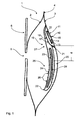
Figure 1 illustrates anostomy bag 1 according to a preferred embodiment of the invention. The ostomy bag comprises arear wall 2 and afront wall 3, that are welded together along theirrim 4. Therear wall 2 has awaste inlet opening 5, which in this embodiment is surrounded by a skin-friendly adhesive 6. Thefilter construction 10 in the ostomy bag comprises adeodorising element 11 and anelongate extension element 20. Thedeodorising element 11 is disc-shaped and comprises foam impregnated withcarbon 12 covered by two gas-impermeable foils 13, 14. The foil 14 facing thefront wall 3 is provided with agas outlet 15 placed in alignment with thevent 16 in the front wall. Thedeodorising element 11 including the cover-foils 13, 14 is further enclosed in anenclosure foil 17 provided with aninlet 18 to the deodorising element. Thus, gas coming from the extension element enters through theinlet 18 in theenclosure foil 17 and from there around thedeodorising element 11 to enter into the carbon-impregnatedfoam 12 at the periphery, radially through theelement 11 towards the centre and exits through the gas-outlet 15 and thevent 16. - The
extension element 20 comprises afirst end 21 and asecond end 22 and anenclosure 23 in between. In this embodiment, theenclosure 23 is provided by afoil layer 24 that is welded at a side (not shown) and at thesecond end 22. Thefoil layer 24 is perforated over a part of the surface so that theextension element 20 is divided into a gas-inlet portion 25 with gas-inlets 26 and anon-permeable portion 27 without gas-inlets. Thus, there is a distance d between the gas-inlet closest to the deodorising element and the first end of the extension element. In this embodiment, theenclosure 23 further includes a foam-element 28, which may function as a further stopper for liquid entering into the extension element and as an element preventing kinking of the extension element. -
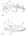
Figure 2 illustrates anotherfilter construction 110 for use in an ostomy bag according to a preferred embodiment of the invention. Thefilter construction 110 includes adeodorising element 111 and an elongated tube-like extension element 120. Thedeodorising element 111 includes a gas-outlet 115, which in use is positioned in an aligned position with the vent of the ostomy bag (not shown). In this embodiment, thedeodorising element 111 further includes aninlet 118. Theextension element 120 is connected to thedeodorising element 111 at afirst end 121 and stretches in a generally longitudinal direction towards asecond end 122. In the embodiment shown, theextension element 120 includesfoam 128 enclosed inside the enclosure 123 of the extension element. At the second end 122 abuoyant element 130 is attached to theextension element 120. Like with the embodiment infigure 1 , theextension element 120 has perforations providing gas-inlets 126 at a gas-inlet portion 125. Again, there is anon-permeable portion 127 closest to thedeodorising element 111. -
Figure 3 illustrates abuoyant element 130. Thisbuoyant element 130 consists of twofoil layers chamber 133 for a piece offoam 134. -
Figure 4 illustrates how afilter construction 210 can be positioned in alignment with thevent 216 in awall 203 of an ostomy bag. Thedeodorising element 211 is, in this embodiment, circular - therefore the connection at thefirst end 221 between theextension element 220 and thedeodorising element 211 is made circular. Furthermore, in this embodiment theextension element 220 consists of two layers offoil foam 228. The two layers offoil inlets 226 in the gas-inlet portion 225. Thenon-permeable portion 227 also appears from the figure. -
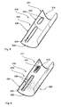
Figures 5 and 6 illustrate two examples of tube like filter constructions. Infigure 5 , thefilter construction 310 comprises a net-foil 324 in theextension element 320 and infigure 6 , thefilter construction 410 comprises aperforated foil 424 in theextension element 420. Thus the gas-inlets 426 appear clearly infigure 6 , while they cannot be seen infigure 5 because they are too small. Thedeodorising element extension element foam element filter construction 310 infigure 5 , thefoil 313 at thedeodorising element 311 is a gas- and liquid impermeable foil, which is welded to the net-foil 324. Alternatively, the net-foil can extend all the way at the deodorising element and be provided with an extra impermeable foil layer. Thefilter construction 310 is made by enclosing thefoam elements foils second end 322 of the extension element. The opposite end of the filter construction is left open to provide for the gas-outlet 315. - In the
filter construction 410, thefoil 424 may extend past thedeodorising element 411. It is only perforated at the gas-inlet portion 425 of the extension element. Thefoil 424 may be welded along the length to enclose bothfoam element second end 422 of the extension element. The gas-outlet 415 is provided in the opposite end of the filter construction.
Claims (10)
Applications Claiming Priority (2)
| Application Number | Priority Date | Filing Date | Title |
|---|---|---|---|
| DKPA201070245 | 2010-06-04 | ||
| PCT/DK2011/050190 WO2011150937A1 (en) | 2010-06-04 | 2011-06-01 | Filter with an extension element |
Publications (2)
| Publication Number | Publication Date |
|---|---|
| EP2575705A1 EP2575705A1 (en) | 2013-04-10 |
| EP2575705B1 true EP2575705B1 (en) | 2015-08-26 |
Family
ID=42357558
Family Applications (1)
| Application Number | Title | Priority Date | Filing Date |
|---|---|---|---|
| EP11726326.9A Active EP2575705B1 (en) | 2010-06-04 | 2011-06-01 | Filter with an extension element |
Country Status (6)
| Country | Link |
|---|---|
| US (1) | US9522079B2 (en) |
| EP (1) | EP2575705B1 (en) |
| CN (1) | CN102917673B (en) |
| BR (1) | BR112012030175B1 (en) |
| RU (1) | RU2565102C2 (en) |
| WO (1) | WO2011150937A1 (en) |
Families Citing this family (19)
| Publication number | Priority date | Publication date | Assignee | Title |
|---|---|---|---|---|
| CN102917673B (en) * | 2010-06-04 | 2015-06-17 | 科洛普拉斯特公司 | Filter with an extension element |
| CN105147440B (en) * | 2010-06-04 | 2017-07-07 | 科洛普拉斯特公司 | A kind of ostomy appliance with filter structure |
| BR112013010757B1 (en) * | 2010-11-08 | 2020-11-03 | Coloplast A/S | ostomy bag |
| US9999536B2 (en) * | 2010-12-27 | 2018-06-19 | Benson Turtleneck Barrier Llc | Ostomy barrier seal |
| US9655765B2 (en) * | 2011-11-15 | 2017-05-23 | Emory University | Extended wear devices for liquid deodorizers and containers including such devices |
| GB2510398B (en) | 2013-02-01 | 2017-10-25 | Salts Healthcare Ltd | Ostomy appliance |
| WO2015132623A1 (en) | 2014-03-03 | 2015-09-11 | Simeonov Simeon Stanchev | Ostomy appliance with venting component |
| EP3166549B1 (en) * | 2014-07-10 | 2019-09-11 | Coloplast A/S | Expandable collecting bag for an ostomy appliance |
| KR101806005B1 (en) * | 2015-07-14 | 2017-12-07 | 주식회사 엘지화학 | Modified poly(arylene ether) resin composition, method for preparing the resin composition, and molded article produced thereof |
| CN108245309A (en) * | 2016-12-29 | 2018-07-06 | 光正龙 | A kind of ostomy bag of multilayer sack |
| EP3582726B1 (en) | 2017-02-20 | 2021-04-14 | Coloplast A/S | An adhesive wafer with an integrated release layer |
| EP3820416B1 (en) * | 2018-07-10 | 2023-09-06 | Hollister Incorporated | Ostomy pouch filter |
| US20220313471A1 (en) * | 2019-06-04 | 2022-10-06 | Hollister Incorporated | Ostomy pouch with filter path and filter |
| EP4218691B1 (en) * | 2019-10-04 | 2024-11-27 | ConvaTec Limited | Ostomy appliance |
| CN114502112B (en) | 2019-10-04 | 2024-09-06 | 康沃特克有限公司 | Ostomy appliances |
| ES2953846T3 (en) * | 2019-10-04 | 2023-11-16 | Convatec Ltd | Ostomy device |
| WO2021209750A2 (en) | 2020-04-15 | 2021-10-21 | Convatec Limited | Ostomy appliance |
| CN114587753B (en) * | 2022-03-09 | 2023-11-03 | 中国人民解放军陆军特色医学中心 | Ostomy bag suitable for weak old-aged ostomy patients |
| JP2025536740A (en) * | 2023-09-05 | 2025-11-07 | ホリスター・インコーポレイテッド | Ostomy filter protection |
Family Cites Families (20)
| Publication number | Priority date | Publication date | Assignee | Title |
|---|---|---|---|---|
| DE2928274A1 (en) * | 1978-07-19 | 1980-02-07 | Matburn Holdings Ltd | SURGICAL RECEPTION BAG |
| GB2124086A (en) | 1982-05-12 | 1984-02-15 | Craig Med Prod Ltd | An ostomy bag particularly for use with a fold-over filter |
| US4553967A (en) * | 1983-10-14 | 1985-11-19 | E. R. Squibb & Sons, Inc. | Wound care and drainage system having hand access port |
| FR2605879B1 (en) * | 1986-10-31 | 1994-01-28 | Biotrol Laboratoires | IMPROVED Ostomy Device |
| FR2613613B1 (en) * | 1987-04-10 | 1990-12-07 | Biotrol Sa Lab | ASSEMBLY DEVICE FOR AN OSTOMY POCKET |
| US5250042A (en) * | 1990-02-20 | 1993-10-05 | E. R. Squibb & Sons, Inc. | Ostomy bag with filter combination |
| US5306264A (en) | 1993-01-14 | 1994-04-26 | E. R. Squibb & Sons, Inc. | Ostomy bag with multi-stage filter |
| US5593397A (en) * | 1995-07-13 | 1997-01-14 | Hollister Incorporated | Fecal collector with elastic attachment patch |
| ATE272991T1 (en) * | 1997-04-08 | 2004-08-15 | Coloplast As | STOMARY APPARATUS |
| DE20021420U1 (en) | 2000-09-02 | 2001-03-08 | Barnickel, Thomas C., 27299 Langwedel | Ostomy pouch |
| DK175870B1 (en) | 2001-09-05 | 2005-05-02 | Coloplast As | An ostomy appliance |
| US20040059306A1 (en) * | 2002-09-23 | 2004-03-25 | Tsal Lawrence M. | Pouch for medical use |
| US20060111682A1 (en) * | 2004-06-24 | 2006-05-25 | Schena Kenneth R | Colostomy bag cleaning system |
| WO2006048019A1 (en) * | 2004-11-03 | 2006-05-11 | Coloplast A/S | A cleanable filter for an ostomy appliance |
| ATE487447T1 (en) * | 2005-06-28 | 2010-11-15 | Coloplast As | STOMACH BAG FILTER WITH INTERACTING SURFACES |
| US8585753B2 (en) * | 2006-03-04 | 2013-11-19 | John James Scanlon | Fibrillated biodegradable prosthesis |
| GB2473206B (en) * | 2009-09-02 | 2014-12-17 | Welland Medical Ltd | A flushable ostomy bag having an outer protective and inner waste collecting pouch |
| CN105147440B (en) * | 2010-06-04 | 2017-07-07 | 科洛普拉斯特公司 | A kind of ostomy appliance with filter structure |
| CN102917673B (en) * | 2010-06-04 | 2015-06-17 | 科洛普拉斯特公司 | Filter with an extension element |
| BR112013010757B1 (en) * | 2010-11-08 | 2020-11-03 | Coloplast A/S | ostomy bag |
-
2011
- 2011-06-01 CN CN201180026617.5A patent/CN102917673B/en active Active
- 2011-06-01 EP EP11726326.9A patent/EP2575705B1/en active Active
- 2011-06-01 BR BR112012030175-6A patent/BR112012030175B1/en active IP Right Grant
- 2011-06-01 WO PCT/DK2011/050190 patent/WO2011150937A1/en not_active Ceased
- 2011-06-01 US US13/701,513 patent/US9522079B2/en active Active
- 2011-06-01 RU RU2012158144/14A patent/RU2565102C2/en active
Also Published As
| Publication number | Publication date |
|---|---|
| RU2012158144A (en) | 2014-07-20 |
| RU2565102C2 (en) | 2015-10-20 |
| BR112012030175B1 (en) | 2020-11-03 |
| BR112012030175A2 (en) | 2016-09-06 |
| EP2575705A1 (en) | 2013-04-10 |
| WO2011150937A1 (en) | 2011-12-08 |
| US9522079B2 (en) | 2016-12-20 |
| CN102917673B (en) | 2015-06-17 |
| US20130072885A1 (en) | 2013-03-21 |
| CN102917673A (en) | 2013-02-06 |
Similar Documents
| Publication | Publication Date | Title |
|---|---|---|
| EP2575705B1 (en) | Filter with an extension element | |
| JP4369242B2 (en) | Hole making tool | |
| EP0981311B1 (en) | An ostomy appliance | |
| ES2362627T3 (en) | DEODORANT FILTER FOR AN OSTOMY DEVICE. | |
| US6328719B1 (en) | Filter and gas vent system incorporated in an ostomy bag | |
| JP2016517764A (en) | Gas filtration and release for stoma appliances | |
| WO2011150936A1 (en) | An ostomy bag with a filter construction | |
| EP2637613B1 (en) | Ostomy bag with intermediate filter element | |
| US4367742A (en) | Ostomy bag | |
| US8758316B2 (en) | Ostomy system | |
| AU2020361074B2 (en) | Ostomy appliance | |
| EP4135639B1 (en) | Ostomy appliance | |
| JP2007082697A (en) | Medical pouch | |
| KR20160033658A (en) | Gas filter and release for ostomy appliance |
Legal Events
| Date | Code | Title | Description |
|---|---|---|---|
| PUAI | Public reference made under article 153(3) epc to a published international application that has entered the european phase |
Free format text: ORIGINAL CODE: 0009012 |
|
| 17P | Request for examination filed |
Effective date: 20130104 |
|
| AK | Designated contracting states |
Kind code of ref document: A1 Designated state(s): AL AT BE BG CH CY CZ DE DK EE ES FI FR GB GR HR HU IE IS IT LI LT LU LV MC MK MT NL NO PL PT RO RS SE SI SK SM TR |
|
| DAX | Request for extension of the european patent (deleted) | ||
| GRAP | Despatch of communication of intention to grant a patent |
Free format text: ORIGINAL CODE: EPIDOSNIGR1 |
|
| INTG | Intention to grant announced |
Effective date: 20141008 |
|
| GRAP | Despatch of communication of intention to grant a patent |
Free format text: ORIGINAL CODE: EPIDOSNIGR1 |
|
| INTG | Intention to grant announced |
Effective date: 20150318 |
|
| RIN1 | Information on inventor provided before grant (corrected) |
Inventor name: TORSTENSEN, JAN Inventor name: SCHERTIGER, LARS, OLAV Inventor name: LUTHER, PREBEN |
|
| GRAS | Grant fee paid |
Free format text: ORIGINAL CODE: EPIDOSNIGR3 |
|
| GRAA | (expected) grant |
Free format text: ORIGINAL CODE: 0009210 |
|
| AK | Designated contracting states |
Kind code of ref document: B1 Designated state(s): AL AT BE BG CH CY CZ DE DK EE ES FI FR GB GR HR HU IE IS IT LI LT LU LV MC MK MT NL NO PL PT RO RS SE SI SK SM TR |
|
| REG | Reference to a national code |
Ref country code: GB Ref legal event code: FG4D |
|
| REG | Reference to a national code |
Ref country code: CH Ref legal event code: EP |
|
| REG | Reference to a national code |
Ref country code: AT Ref legal event code: REF Ref document number: 744711 Country of ref document: AT Kind code of ref document: T Effective date: 20150915 |
|
| REG | Reference to a national code |
Ref country code: IE Ref legal event code: FG4D |
|
| REG | Reference to a national code |
Ref country code: DE Ref legal event code: R096 Ref document number: 602011019158 Country of ref document: DE |
|
| REG | Reference to a national code |
Ref country code: AT Ref legal event code: MK05 Ref document number: 744711 Country of ref document: AT Kind code of ref document: T Effective date: 20150826 |
|
| REG | Reference to a national code |
Ref country code: LT Ref legal event code: MG4D |
|
| PG25 | Lapsed in a contracting state [announced via postgrant information from national office to epo] |
Ref country code: LV Free format text: LAPSE BECAUSE OF FAILURE TO SUBMIT A TRANSLATION OF THE DESCRIPTION OR TO PAY THE FEE WITHIN THE PRESCRIBED TIME-LIMIT Effective date: 20150826 Ref country code: FI Free format text: LAPSE BECAUSE OF FAILURE TO SUBMIT A TRANSLATION OF THE DESCRIPTION OR TO PAY THE FEE WITHIN THE PRESCRIBED TIME-LIMIT Effective date: 20150826 Ref country code: GR Free format text: LAPSE BECAUSE OF FAILURE TO SUBMIT A TRANSLATION OF THE DESCRIPTION OR TO PAY THE FEE WITHIN THE PRESCRIBED TIME-LIMIT Effective date: 20151127 Ref country code: LT Free format text: LAPSE BECAUSE OF FAILURE TO SUBMIT A TRANSLATION OF THE DESCRIPTION OR TO PAY THE FEE WITHIN THE PRESCRIBED TIME-LIMIT Effective date: 20150826 Ref country code: NO Free format text: LAPSE BECAUSE OF FAILURE TO SUBMIT A TRANSLATION OF THE DESCRIPTION OR TO PAY THE FEE WITHIN THE PRESCRIBED TIME-LIMIT Effective date: 20151126 |
|
| REG | Reference to a national code |
Ref country code: NL Ref legal event code: MP Effective date: 20150826 |
|
| PG25 | Lapsed in a contracting state [announced via postgrant information from national office to epo] |
Ref country code: AT Free format text: LAPSE BECAUSE OF FAILURE TO SUBMIT A TRANSLATION OF THE DESCRIPTION OR TO PAY THE FEE WITHIN THE PRESCRIBED TIME-LIMIT Effective date: 20150826 Ref country code: PT Free format text: LAPSE BECAUSE OF FAILURE TO SUBMIT A TRANSLATION OF THE DESCRIPTION OR TO PAY THE FEE WITHIN THE PRESCRIBED TIME-LIMIT Effective date: 20151228 Ref country code: ES Free format text: LAPSE BECAUSE OF FAILURE TO SUBMIT A TRANSLATION OF THE DESCRIPTION OR TO PAY THE FEE WITHIN THE PRESCRIBED TIME-LIMIT Effective date: 20150826 Ref country code: RS Free format text: LAPSE BECAUSE OF FAILURE TO SUBMIT A TRANSLATION OF THE DESCRIPTION OR TO PAY THE FEE WITHIN THE PRESCRIBED TIME-LIMIT Effective date: 20150826 Ref country code: SE Free format text: LAPSE BECAUSE OF FAILURE TO SUBMIT A TRANSLATION OF THE DESCRIPTION OR TO PAY THE FEE WITHIN THE PRESCRIBED TIME-LIMIT Effective date: 20150826 Ref country code: IS Free format text: LAPSE BECAUSE OF FAILURE TO SUBMIT A TRANSLATION OF THE DESCRIPTION OR TO PAY THE FEE WITHIN THE PRESCRIBED TIME-LIMIT Effective date: 20151226 Ref country code: PL Free format text: LAPSE BECAUSE OF FAILURE TO SUBMIT A TRANSLATION OF THE DESCRIPTION OR TO PAY THE FEE WITHIN THE PRESCRIBED TIME-LIMIT Effective date: 20150826 Ref country code: HR Free format text: LAPSE BECAUSE OF FAILURE TO SUBMIT A TRANSLATION OF THE DESCRIPTION OR TO PAY THE FEE WITHIN THE PRESCRIBED TIME-LIMIT Effective date: 20150826 |
|
| PG25 | Lapsed in a contracting state [announced via postgrant information from national office to epo] |
Ref country code: NL Free format text: LAPSE BECAUSE OF FAILURE TO SUBMIT A TRANSLATION OF THE DESCRIPTION OR TO PAY THE FEE WITHIN THE PRESCRIBED TIME-LIMIT Effective date: 20150826 |
|
| REG | Reference to a national code |
Ref country code: FR Ref legal event code: PLFP Year of fee payment: 6 |
|
| PG25 | Lapsed in a contracting state [announced via postgrant information from national office to epo] |
Ref country code: CZ Free format text: LAPSE BECAUSE OF FAILURE TO SUBMIT A TRANSLATION OF THE DESCRIPTION OR TO PAY THE FEE WITHIN THE PRESCRIBED TIME-LIMIT Effective date: 20150826 Ref country code: IT Free format text: LAPSE BECAUSE OF FAILURE TO SUBMIT A TRANSLATION OF THE DESCRIPTION OR TO PAY THE FEE WITHIN THE PRESCRIBED TIME-LIMIT Effective date: 20150826 Ref country code: SK Free format text: LAPSE BECAUSE OF FAILURE TO SUBMIT A TRANSLATION OF THE DESCRIPTION OR TO PAY THE FEE WITHIN THE PRESCRIBED TIME-LIMIT Effective date: 20150826 Ref country code: DK Free format text: LAPSE BECAUSE OF FAILURE TO SUBMIT A TRANSLATION OF THE DESCRIPTION OR TO PAY THE FEE WITHIN THE PRESCRIBED TIME-LIMIT Effective date: 20150826 Ref country code: EE Free format text: LAPSE BECAUSE OF FAILURE TO SUBMIT A TRANSLATION OF THE DESCRIPTION OR TO PAY THE FEE WITHIN THE PRESCRIBED TIME-LIMIT Effective date: 20150826 |
|
| REG | Reference to a national code |
Ref country code: DE Ref legal event code: R097 Ref document number: 602011019158 Country of ref document: DE |
|
| PG25 | Lapsed in a contracting state [announced via postgrant information from national office to epo] |
Ref country code: RO Free format text: LAPSE BECAUSE OF FAILURE TO SUBMIT A TRANSLATION OF THE DESCRIPTION OR TO PAY THE FEE WITHIN THE PRESCRIBED TIME-LIMIT Effective date: 20150826 |
|
| PLBE | No opposition filed within time limit |
Free format text: ORIGINAL CODE: 0009261 |
|
| STAA | Information on the status of an ep patent application or granted ep patent |
Free format text: STATUS: NO OPPOSITION FILED WITHIN TIME LIMIT |
|
| 26N | No opposition filed |
Effective date: 20160530 |
|
| PG25 | Lapsed in a contracting state [announced via postgrant information from national office to epo] |
Ref country code: SI Free format text: LAPSE BECAUSE OF FAILURE TO SUBMIT A TRANSLATION OF THE DESCRIPTION OR TO PAY THE FEE WITHIN THE PRESCRIBED TIME-LIMIT Effective date: 20150826 |
|
| PG25 | Lapsed in a contracting state [announced via postgrant information from national office to epo] |
Ref country code: BE Free format text: LAPSE BECAUSE OF FAILURE TO SUBMIT A TRANSLATION OF THE DESCRIPTION OR TO PAY THE FEE WITHIN THE PRESCRIBED TIME-LIMIT Effective date: 20150826 |
|
| PG25 | Lapsed in a contracting state [announced via postgrant information from national office to epo] |
Ref country code: MC Free format text: LAPSE BECAUSE OF FAILURE TO SUBMIT A TRANSLATION OF THE DESCRIPTION OR TO PAY THE FEE WITHIN THE PRESCRIBED TIME-LIMIT Effective date: 20150826 |
|
| REG | Reference to a national code |
Ref country code: CH Ref legal event code: PL |
|
| REG | Reference to a national code |
Ref country code: IE Ref legal event code: MM4A |
|
| REG | Reference to a national code |
Ref country code: FR Ref legal event code: PLFP Year of fee payment: 7 |
|
| PG25 | Lapsed in a contracting state [announced via postgrant information from national office to epo] |
Ref country code: LI Free format text: LAPSE BECAUSE OF NON-PAYMENT OF DUE FEES Effective date: 20160630 Ref country code: CH Free format text: LAPSE BECAUSE OF NON-PAYMENT OF DUE FEES Effective date: 20160630 |
|
| PG25 | Lapsed in a contracting state [announced via postgrant information from national office to epo] |
Ref country code: IE Free format text: LAPSE BECAUSE OF NON-PAYMENT OF DUE FEES Effective date: 20160601 |
|
| REG | Reference to a national code |
Ref country code: FR Ref legal event code: PLFP Year of fee payment: 8 |
|
| PG25 | Lapsed in a contracting state [announced via postgrant information from national office to epo] |
Ref country code: SM Free format text: LAPSE BECAUSE OF FAILURE TO SUBMIT A TRANSLATION OF THE DESCRIPTION OR TO PAY THE FEE WITHIN THE PRESCRIBED TIME-LIMIT Effective date: 20150826 Ref country code: HU Free format text: LAPSE BECAUSE OF FAILURE TO SUBMIT A TRANSLATION OF THE DESCRIPTION OR TO PAY THE FEE WITHIN THE PRESCRIBED TIME-LIMIT; INVALID AB INITIO Effective date: 20110601 Ref country code: CY Free format text: LAPSE BECAUSE OF FAILURE TO SUBMIT A TRANSLATION OF THE DESCRIPTION OR TO PAY THE FEE WITHIN THE PRESCRIBED TIME-LIMIT Effective date: 20150826 |
|
| PG25 | Lapsed in a contracting state [announced via postgrant information from national office to epo] |
Ref country code: LU Free format text: LAPSE BECAUSE OF NON-PAYMENT OF DUE FEES Effective date: 20160601 Ref country code: TR Free format text: LAPSE BECAUSE OF FAILURE TO SUBMIT A TRANSLATION OF THE DESCRIPTION OR TO PAY THE FEE WITHIN THE PRESCRIBED TIME-LIMIT Effective date: 20150826 Ref country code: MK Free format text: LAPSE BECAUSE OF FAILURE TO SUBMIT A TRANSLATION OF THE DESCRIPTION OR TO PAY THE FEE WITHIN THE PRESCRIBED TIME-LIMIT Effective date: 20150826 Ref country code: MT Free format text: LAPSE BECAUSE OF NON-PAYMENT OF DUE FEES Effective date: 20160630 |
|
| PG25 | Lapsed in a contracting state [announced via postgrant information from national office to epo] |
Ref country code: BG Free format text: LAPSE BECAUSE OF FAILURE TO SUBMIT A TRANSLATION OF THE DESCRIPTION OR TO PAY THE FEE WITHIN THE PRESCRIBED TIME-LIMIT Effective date: 20150826 |
|
| PG25 | Lapsed in a contracting state [announced via postgrant information from national office to epo] |
Ref country code: AL Free format text: LAPSE BECAUSE OF FAILURE TO SUBMIT A TRANSLATION OF THE DESCRIPTION OR TO PAY THE FEE WITHIN THE PRESCRIBED TIME-LIMIT Effective date: 20150826 |
|
| PGFP | Annual fee paid to national office [announced via postgrant information from national office to epo] |
Ref country code: DE Payment date: 20250627 Year of fee payment: 15 |
|
| PGFP | Annual fee paid to national office [announced via postgrant information from national office to epo] |
Ref country code: GB Payment date: 20250627 Year of fee payment: 15 |
|
| PGFP | Annual fee paid to national office [announced via postgrant information from national office to epo] |
Ref country code: FR Payment date: 20250625 Year of fee payment: 15 |