EP2575655B1 - Knochenplatte - Google Patents
Knochenplatte Download PDFInfo
- Publication number
- EP2575655B1 EP2575655B1 EP11719740.0A EP11719740A EP2575655B1 EP 2575655 B1 EP2575655 B1 EP 2575655B1 EP 11719740 A EP11719740 A EP 11719740A EP 2575655 B1 EP2575655 B1 EP 2575655B1
- Authority
- EP
- European Patent Office
- Prior art keywords
- hole
- bone
- thread
- bone plate
- peripheral
- Prior art date
- Legal status (The legal status is an assumption and is not a legal conclusion. Google has not performed a legal analysis and makes no representation as to the accuracy of the status listed.)
- Active
Links
Images

Classifications
-
- A—HUMAN NECESSITIES
- A61—MEDICAL OR VETERINARY SCIENCE; HYGIENE
- A61B—DIAGNOSIS; SURGERY; IDENTIFICATION
- A61B17/00—Surgical instruments, devices or methods
- A61B17/56—Surgical instruments or methods for treatment of bones or joints; Devices specially adapted therefor
- A61B17/58—Surgical instruments or methods for treatment of bones or joints; Devices specially adapted therefor for osteosynthesis, e.g. bone plates, screws or setting implements
- A61B17/68—Internal fixation devices, including fasteners and spinal fixators, even if a part thereof projects from the skin
- A61B17/80—Cortical plates, i.e. bone plates; Instruments for holding or positioning cortical plates, or for compressing bones attached to cortical plates
- A61B17/8052—Cortical plates, i.e. bone plates; Instruments for holding or positioning cortical plates, or for compressing bones attached to cortical plates immobilised relative to screws by interlocking form of the heads and plate holes, e.g. conical or threaded
- A61B17/8057—Cortical plates, i.e. bone plates; Instruments for holding or positioning cortical plates, or for compressing bones attached to cortical plates immobilised relative to screws by interlocking form of the heads and plate holes, e.g. conical or threaded the interlocking form comprising a thread
-
- A—HUMAN NECESSITIES
- A61—MEDICAL OR VETERINARY SCIENCE; HYGIENE
- A61B—DIAGNOSIS; SURGERY; IDENTIFICATION
- A61B17/00—Surgical instruments, devices or methods
- A61B17/56—Surgical instruments or methods for treatment of bones or joints; Devices specially adapted therefor
- A61B17/58—Surgical instruments or methods for treatment of bones or joints; Devices specially adapted therefor for osteosynthesis, e.g. bone plates, screws or setting implements
- A61B17/68—Internal fixation devices, including fasteners and spinal fixators, even if a part thereof projects from the skin
- A61B17/80—Cortical plates, i.e. bone plates; Instruments for holding or positioning cortical plates, or for compressing bones attached to cortical plates
- A61B17/8052—Cortical plates, i.e. bone plates; Instruments for holding or positioning cortical plates, or for compressing bones attached to cortical plates immobilised relative to screws by interlocking form of the heads and plate holes, e.g. conical or threaded
-
- A—HUMAN NECESSITIES
- A61—MEDICAL OR VETERINARY SCIENCE; HYGIENE
- A61B—DIAGNOSIS; SURGERY; IDENTIFICATION
- A61B17/00—Surgical instruments, devices or methods
- A61B17/56—Surgical instruments or methods for treatment of bones or joints; Devices specially adapted therefor
- A61B17/58—Surgical instruments or methods for treatment of bones or joints; Devices specially adapted therefor for osteosynthesis, e.g. bone plates, screws or setting implements
- A61B17/68—Internal fixation devices, including fasteners and spinal fixators, even if a part thereof projects from the skin
- A61B17/84—Fasteners therefor or fasteners being internal fixation devices
- A61B17/86—Pins or screws or threaded wires; nuts therefor
-
- A—HUMAN NECESSITIES
- A61—MEDICAL OR VETERINARY SCIENCE; HYGIENE
- A61L—METHODS OR APPARATUS FOR STERILISING MATERIALS OR OBJECTS IN GENERAL; DISINFECTION, STERILISATION OR DEODORISATION OF AIR; CHEMICAL ASPECTS OF BANDAGES, DRESSINGS, ABSORBENT PADS OR SURGICAL ARTICLES; MATERIALS FOR BANDAGES, DRESSINGS, ABSORBENT PADS OR SURGICAL ARTICLES
- A61L27/00—Materials for grafts or prostheses or for coating grafts or prostheses
- A61L27/02—Inorganic materials
- A61L27/04—Metals or alloys
-
- A—HUMAN NECESSITIES
- A61—MEDICAL OR VETERINARY SCIENCE; HYGIENE
- A61B—DIAGNOSIS; SURGERY; IDENTIFICATION
- A61B17/00—Surgical instruments, devices or methods
- A61B17/56—Surgical instruments or methods for treatment of bones or joints; Devices specially adapted therefor
- A61B17/58—Surgical instruments or methods for treatment of bones or joints; Devices specially adapted therefor for osteosynthesis, e.g. bone plates, screws or setting implements
- A61B17/68—Internal fixation devices, including fasteners and spinal fixators, even if a part thereof projects from the skin
- A61B17/70—Spinal positioners or stabilisers, e.g. stabilisers comprising fluid filler in an implant
- A61B17/7059—Cortical plates
-
- A—HUMAN NECESSITIES
- A61—MEDICAL OR VETERINARY SCIENCE; HYGIENE
- A61B—DIAGNOSIS; SURGERY; IDENTIFICATION
- A61B17/00—Surgical instruments, devices or methods
- A61B17/56—Surgical instruments or methods for treatment of bones or joints; Devices specially adapted therefor
- A61B17/58—Surgical instruments or methods for treatment of bones or joints; Devices specially adapted therefor for osteosynthesis, e.g. bone plates, screws or setting implements
- A61B17/68—Internal fixation devices, including fasteners and spinal fixators, even if a part thereof projects from the skin
- A61B17/80—Cortical plates, i.e. bone plates; Instruments for holding or positioning cortical plates, or for compressing bones attached to cortical plates
- A61B17/8061—Cortical plates, i.e. bone plates; Instruments for holding or positioning cortical plates, or for compressing bones attached to cortical plates specially adapted for particular bones
Definitions
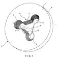
- the bone plate comprises two or more peripheral holes connected to and open to a through hole.
- the peripheral holes include a thread for receiving peripheral bone screws therein.
- the two or more peripheral holes are arranged peripherally around the through hole in such a way that they overlap with the through hole to form a composite hole structure able to receive two or more peripheral bone screws therein while a central bone screw is received in the through hole.
- the screw head of the central bone screw is conically or spherically shaped and the screw heads of the peripheral bone screws are conically or spherically shaped.
- the kit comprises more than one central bone screws with differently shaped screw heads and a number of 2 x N peripheral bone screws with differently shaped screw heads.
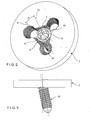
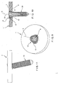
- the through hole 9 tapers radially inward toward the distal surface 8 of the bone plate 1.
- a central bone screw 30 with a screw axis 33 and a screw head 31 is inserted in the through hole 9.
- the screw head 31 is spherically shaped and comprises an external thread 32 so that the central bone screw 30 can be inserted into the through hole at a user-selected angle ⁇ between the screw axis 33 and the longitudinal axis 6 of the through hole 9.
- the peripheral holes 2 are configured so that each of the hole axes 11 is angled at approximately 20° relative to the longitudinal axis 6 of the through hole 9.
- the peripheral holes 2 may be angled at any other angle relative to the longitudinal axis 6 and may optionally also each extend along different angles, as those skilled in the art will understand.
- each of the peripheral holes 2 tapers radially inward towards the distal surface 8 of the bone plate 1.
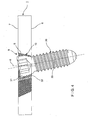
- a peripheral bone screw 20 with a screw axis 23 and a screw head 21 is inserted into each of the peripheral holes 2.
- the screw head 21 is conically shaped and comprises an external thread 22 so each peripheral bone screw 20 can be inserted into one of the peripheral holes 2 at a fixed angle with the screw axis 23 and the hole axis 11 of the peripheral hole 2 coinciding.
- the through hole 9 tapers towards the distal surface 8 of the bone plate 1.
- a central bone screw 30 with a screw axis 33 and a screw head 31 is inserted in the through hole 9.
- the screw head 31 is spherically shaped and comprises an external thread 32 so that the central bone screw 30 can be inserted into the through hole at a user-selected variable angle ⁇ between the screw axis 33 and the longitudinal axis 6 of the through hole 9.
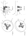
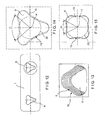
- Figs. 12 to 14 another embodiment of the bone plate 1 is illustrated which comprises two through holes 9.
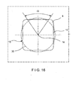
- the depth of thread of the thread 5 or thread-like structure decreases on each end of the convex section 15 at the transition between the convex section 15 and the concavely rounded section in such a way that a portion of the concavely rounded sections is unthreaded.
Landscapes
- Health & Medical Sciences (AREA)
- Orthopedic Medicine & Surgery (AREA)
- Life Sciences & Earth Sciences (AREA)
- Surgery (AREA)
- Veterinary Medicine (AREA)
- Public Health (AREA)
- General Health & Medical Sciences (AREA)
- Animal Behavior & Ethology (AREA)
- Neurology (AREA)
- Molecular Biology (AREA)
- Medical Informatics (AREA)
- Heart & Thoracic Surgery (AREA)
- Biomedical Technology (AREA)
- Engineering & Computer Science (AREA)
- Nuclear Medicine, Radiotherapy & Molecular Imaging (AREA)
- Chemical & Material Sciences (AREA)
- Inorganic Chemistry (AREA)
- Dermatology (AREA)
- Medicinal Chemistry (AREA)
- Oral & Maxillofacial Surgery (AREA)
- Transplantation (AREA)
- Epidemiology (AREA)
- Surgical Instruments (AREA)
Claims (16)
- Knochenplatte (1) umfassend:ein erstes Durchgangsloch (9), das sich durch die Platte (1) entlang einer ersten Längsachse (6) von einer proximalen Oberfläche (7) der Platte (1) zu einer dem Knochen zugewandten distalen Oberfläche (8) davon erstreckt, die, wenn die Platte (1) auf einem Zielabschnitt des Knochens in einer gewünschten Ausrichtung platziert ist, dem Knochen zugewandt ist, wobei eine Außenwand (10) des ersten Durchgangslochs (9) drei Wandabschnitte (15) umfasst, die mit Vorsprüngen versehen sind, um einen Schraubenkopf einer Knochenschraube (30) aufzunehmen, wobei die drei Wandabschnitte (15) eines von gerade und konvex sind;wobei die Knochenplatte (1) zusätzlich umfasst:mehrere erste periphere Löchern (2), wobei sich jedes der ersten peripheren Löchern (2) durch die Knochenplatte (1) von der proximalen Oberfläche (7) zur distalen Oberfläche (8) davon entlang einer entsprechenden ersten Lochachse (11) erstreckt und zur Aufnahme von Schraubenköpfen von peripheren Knochenschrauben konfiguriert ist, wobei jedes der ersten peripheren Löcher (2) einen Umfang des ersten Durchgangslochs (9) überlappt, um eine Verbundlochstruktur zu bilden, die zur Aufnahme von peripheren Knochenschrauben durch die ersten peripheren Löcher (2) und einer zentralen Knochenschraube durch das erste Durchgangsloch (9) konfiguriert ist.
- Knochenplatte nach Anspruch 1, dadurch gekennzeichnet, dass eine Querschnittsform des ersten Durchgangslochs (9), die sich orthogonal zur ersten Längsachse (6) erstreckt, polygonal mit abgerundeten Ecken ist.
- Knochenplatte nach Anspruch 1, dadurch gekennzeichnet, dass sich das erste Durchgangsloch (9) größenbezogen in eine Richtung von der proximalen Oberfläche (7) hin zur distalen Oberfläche (8) der Knochenplatte (1) verjüngt.
- Knochenplatte nach Anspruch 1, dadurch gekennzeichnet, dass die Vorsprünge eines von einem Gewinde und einer gewindeähnlichen Struktur umfassen, das bzw. die sich über eine gesamte Länge von jedem der Wandabschnitte (15) erstreckt.
- Knochenplatte nach Anspruch 4, dadurch gekennzeichnet, dass das eine von einem Gewinde und einer gewindeähnlichen Struktur eine konstante Gewindetiefe in den Wandabschnitten (15) hat.
- Knochenplatte nach Anspruch 4, dadurch gekennzeichnet, dass eine Gewindetiefe des einen von einem Gewinde und einer gewindeähnlichen Struktur hin zu proximalen und distalen Enden von jedem der Wandabschnitte (15) abnimmt, wobei die Gewindetiefe in einem zentralen Abschnitt der Wandabschnitte (15) zwischen den proximalen und distalen Oberflächen am größten ist.
- Knochenplatte nach Anspruch 4, dadurch gekennzeichnet, dass eine Gewindetiefe des einen von einem Gewinde und einer gewindeähnlichen Struktur hin zu proximalen und distalen Enden von jedem der Wandabschnitte (15) zunimmt, wobei die Gewindetiefe in einem zentralen Abschnitt der Wandabschnitte (15) zwischen den proximalen und distalen Oberflächen am geringsten ist.
- Knochenplatte nach Anspruch 1, dadurch gekennzeichnet, dass jedes der ersten peripheren Löcher (2) eine kugelförmige Ausnehmung (25) umfasst, die die Knochenplatte (1) von der proximalen Oberfläche (7) teilweise durchdringt.
- Knochenplatte nach Anspruch 1, dadurch gekennzeichnet, dass jedes der ersten peripheren Löcher (2) ein Gewinde zum Verriegeln einer peripheren Knochenschraube darin in einem festen Winkel in Bezug auf die entsprechende erste Lochachse (11) umfasst, und wobei das erste Durchgangsloch (9) ein Gewinde umfasst, das so konfiguriert ist, dass es eine darin eingesetzte Knochenschraube in einem Winkel in Bezug auf die erste Längsachse (6) verriegelt, der von einem Benutzer ausgewählt ist.
- Knochenplatte nach Anspruch 1, dadurch gekennzeichnet, dass jedes der ersten peripheren Löcher (2) ein Gewinde enthält, das so konfiguriert ist, dass es eine periphere Knochenschraube darin in einem Winkel in Bezug auf die entsprechende erste Lochachse (11) verriegelt, der von einem Benutzer ausgewählt ist, und wobei das erste Durchgangsloch (9) ein Gewinde enthält, das so konfiguriert ist, dass es eine Knochenschraube darin in einem festen Winkel in Bezug auf die erste Längsachse (6) verriegelt.
- Knochenplatte nach Anspruch 9, dadurch gekennzeichnet, dass sich das Gewinde über zumindest eine Hälfte eines Umfangs von jedem der ersten peripheren Löcher (2) erstreckt.
- Knochenplatte nach Anspruch 1, dadurch gekennzeichnet, dass das erste Durchgangsloch (9) polygonal ist und jedes der ersten peripheren Löcher (2) in einer Ecke des ersten Durchgangslochs (9) angeordnet ist.
- Knochenplatte nach Anspruch 12, dadurch gekennzeichnet, dass die erste Lochachse (11) eines ersten der ersten peripheren Löcher (2) in Bezug auf die erste Längsachse (6) in einem Winkel zwischen ± 5 ° und ± 20 ° ausgerichtet ist.
- Knochenplatte nach Anspruch 1, zusätzlich umfassend:ein zweites Durchgangsloch (9), wobei eine Außenwand des zweiten Durchgangslochs drei Wandabschnitte enthält, die eines von gerade und konvex sind.
- Knochenplatte nach einem der Ansprüche 1 bis 14, dadurch gekennzeichnet, dass die Außenwand (10) des Durchgangslochs (9) N > 3 nichtkonkave Wandabschnitte (15) enthält.
- Kit zur Knochenfixierung umfassend:eine Knochenplatte (1) nach einem der Ansprüche 1 bis 15, undeine zentrale Knochenschraube, die so konfiguriert ist, dass sie durch das Durchgangsloch (9) eingesetzt wird, wobei die zentrale Knochenschraube einen Gewindekopf von einer derartigen Größe und Form enthält, dass er mit den Vorsprüngen im Durchgangsloch in verriegelnden Eingriff gelangt; undN periphere Knochenschrauben, wobei jede der peripheren Knochenschrauben von einer derartigen Größe und Form ist, dass sie durch ein entsprechendes der peripheren Löcher eingesetzt wird.
Priority Applications (2)
| Application Number | Priority Date | Filing Date | Title |
|---|---|---|---|
| EP14003456.2A EP2826432B1 (de) | 2010-06-02 | 2011-05-04 | Knochenplatte |
| EP20152934.4A EP3659535B1 (de) | 2010-06-02 | 2011-05-04 | Knochenplatte |
Applications Claiming Priority (2)
| Application Number | Priority Date | Filing Date | Title |
|---|---|---|---|
| US35069110P | 2010-06-02 | 2010-06-02 | |
| PCT/US2011/035181 WO2011152951A1 (en) | 2010-06-02 | 2011-05-04 | Bone plate |
Related Child Applications (3)
| Application Number | Title | Priority Date | Filing Date |
|---|---|---|---|
| EP20152934.4A Division EP3659535B1 (de) | 2010-06-02 | 2011-05-04 | Knochenplatte |
| EP14003456.2A Division EP2826432B1 (de) | 2010-06-02 | 2011-05-04 | Knochenplatte |
| EP14003456.2A Division-Into EP2826432B1 (de) | 2010-06-02 | 2011-05-04 | Knochenplatte |
Publications (2)
| Publication Number | Publication Date |
|---|---|
| EP2575655A1 EP2575655A1 (de) | 2013-04-10 |
| EP2575655B1 true EP2575655B1 (de) | 2014-12-10 |
Family
ID=44259957
Family Applications (3)
| Application Number | Title | Priority Date | Filing Date |
|---|---|---|---|
| EP11719740.0A Active EP2575655B1 (de) | 2010-06-02 | 2011-05-04 | Knochenplatte |
| EP20152934.4A Active EP3659535B1 (de) | 2010-06-02 | 2011-05-04 | Knochenplatte |
| EP14003456.2A Active EP2826432B1 (de) | 2010-06-02 | 2011-05-04 | Knochenplatte |
Family Applications After (2)
| Application Number | Title | Priority Date | Filing Date |
|---|---|---|---|
| EP20152934.4A Active EP3659535B1 (de) | 2010-06-02 | 2011-05-04 | Knochenplatte |
| EP14003456.2A Active EP2826432B1 (de) | 2010-06-02 | 2011-05-04 | Knochenplatte |
Country Status (8)
| Country | Link |
|---|---|
| US (3) | US9801669B2 (de) |
| EP (3) | EP2575655B1 (de) |
| JP (2) | JP5918223B2 (de) |
| KR (1) | KR101885507B1 (de) |
| CN (1) | CN102933165B (de) |
| BR (1) | BR112012030248A2 (de) |
| CA (1) | CA2797124A1 (de) |
| WO (1) | WO2011152951A1 (de) |
Cited By (1)
| Publication number | Priority date | Publication date | Assignee | Title |
|---|---|---|---|---|
| US9510880B2 (en) | 2013-08-13 | 2016-12-06 | Zimmer, Inc. | Polyaxial locking mechanism |
Families Citing this family (23)
| Publication number | Priority date | Publication date | Assignee | Title |
|---|---|---|---|---|
| US11259851B2 (en) | 2003-08-26 | 2022-03-01 | DePuy Synthes Products, Inc. | Bone plate |
| US11291484B2 (en) | 2004-01-26 | 2022-04-05 | DePuy Synthes Products, Inc. | Highly-versatile variable-angle bone plate system |
| US8834536B2 (en) * | 2009-07-16 | 2014-09-16 | Nexxt Spine, LLC | Cervical plate fixation system |
| US20150105829A1 (en) * | 2012-05-22 | 2015-04-16 | Austofix Group Limited | Bone fixation device |
| US20140066998A1 (en) * | 2012-09-06 | 2014-03-06 | Jean-Jacques Martin | Assembly comprising an implantable part designed to be fastened to one or more bones or bone portions to be joined, and at least one screw for fastening the implantable part to said bone(s) |
| US9404525B2 (en) * | 2013-03-14 | 2016-08-02 | Imds Llc | Polyaxial locking interface |
| US9103367B2 (en) | 2013-03-14 | 2015-08-11 | Imds Llc | Polyaxial locking interface |
| US10231766B2 (en) * | 2013-12-23 | 2019-03-19 | Smith & Nephew, Inc. | Distal radius plate |
| USD779065S1 (en) | 2014-10-08 | 2017-02-14 | Nuvasive, Inc. | Anterior cervical bone plate |
| KR101722747B1 (ko) * | 2015-02-25 | 2017-04-03 | 주식회사 제일메디칼코퍼레이션 | 본 플레이트 시스템 |
| CN104739496A (zh) * | 2015-03-12 | 2015-07-01 | 创辉医疗器械江苏有限公司 | 密螺纹万向接骨板 |
| GB2542350A (en) * | 2015-05-15 | 2017-03-22 | N2 (Uk) Ltd | Method of creating polyaxial threads and a workpiece with a novel polyaxial thread |
| CN105342680A (zh) * | 2015-10-13 | 2016-02-24 | 广州聚生生物科技有限公司 | 一种颈椎前路钢板cage一体化内固定系统 |
| US10820930B2 (en) | 2016-09-08 | 2020-11-03 | DePuy Synthes Products, Inc. | Variable angle bone plate |
| US10624686B2 (en) | 2016-09-08 | 2020-04-21 | DePuy Synthes Products, Inc. | Variable angel bone plate |
| US10905476B2 (en) | 2016-09-08 | 2021-02-02 | DePuy Synthes Products, Inc. | Variable angle bone plate |
| US11026727B2 (en) | 2018-03-20 | 2021-06-08 | DePuy Synthes Products, Inc. | Bone plate with form-fitting variable-angle locking hole |
| US10772665B2 (en) * | 2018-03-29 | 2020-09-15 | DePuy Synthes Products, Inc. | Locking structures for affixing bone anchors to a bone plate, and related systems and methods |
| US11013541B2 (en) * | 2018-04-30 | 2021-05-25 | DePuy Synthes Products, Inc. | Threaded locking structures for affixing bone anchors to a bone plate, and related systems and methods |
| US10925651B2 (en) | 2018-12-21 | 2021-02-23 | DePuy Synthes Products, Inc. | Implant having locking holes with collection cavity for shavings |
| US12070253B2 (en) * | 2019-06-07 | 2024-08-27 | Smith & Nephew, Inc. | Orthopedic implant with improved variable angle locking mechanism |
| GB201913436D0 (en) * | 2019-09-18 | 2019-10-30 | Depuy Ireland Ultd Co | Cutting block |
| US20260000515A1 (en) * | 2024-06-27 | 2026-01-01 | George J. Haidukewych | Acetabular prosthesis systems and surgical methods |
Family Cites Families (15)
| Publication number | Priority date | Publication date | Assignee | Title |
|---|---|---|---|---|
| DE69839011T2 (de) * | 1997-02-11 | 2009-01-08 | Warsaw Orthopedic, Inc., Warsaw | Vorrichtung zum anbringen von skelettplatten |
| ZA983955B (en) * | 1997-05-15 | 2001-08-13 | Sdgi Holdings Inc | Anterior cervical plating system. |
| FR2848413B1 (fr) * | 2002-12-11 | 2005-07-29 | Fixano | Plaque d'osteosynthese pour l'osteosynthese de petits os voisins les uns des autres |
| US7309340B2 (en) * | 2003-06-20 | 2007-12-18 | Medicinelodge, Inc. | Method and apparatus for bone plating |
| DE20321552U1 (de) * | 2003-08-26 | 2007-12-27 | Synthes Gmbh | Knochenplatte |
| US8574268B2 (en) * | 2004-01-26 | 2013-11-05 | DePuy Synthes Product, LLC | Highly-versatile variable-angle bone plate system |
| DE102005042766B4 (de) * | 2005-07-13 | 2009-08-20 | Königsee Implantate und Instrumente zur Osteosynthese GmbH | Plattenloch einer Knochenplatte für die Osteosynthese |
| US8382807B2 (en) * | 2005-07-25 | 2013-02-26 | Smith & Nephew, Inc. | Systems and methods for using polyaxial plates |
| CN101272743B (zh) | 2005-07-25 | 2011-01-26 | 史密夫和内修有限公司 | 使用多轴式板的系统 |
| DE202006019220U1 (de) * | 2006-12-19 | 2007-05-24 | Zrinski Ag | Orthopädisches Schraubenverschlusssystem |
| WO2009058969A1 (en) | 2007-10-30 | 2009-05-07 | Synthes (U.S.A.) | Variable angle locked bone plate |
| JP5805624B2 (ja) * | 2009-04-24 | 2015-11-04 | シンセス ゲゼルシャフト ミット ベシュレンクテル ハフツングSynthes Gmbh | 多重スクリュー |
| CN201469392U (zh) | 2009-08-07 | 2010-05-19 | 武汉德骼拜尔外科植入物有限公司 | 一种异型锁定型接骨板 |
| US9404525B2 (en) * | 2013-03-14 | 2016-08-02 | Imds Llc | Polyaxial locking interface |
| US9545277B2 (en) * | 2014-03-11 | 2017-01-17 | DePuy Synthes Products, Inc. | Bone plate |
-
2011
- 2011-05-04 EP EP11719740.0A patent/EP2575655B1/de active Active
- 2011-05-04 CA CA2797124A patent/CA2797124A1/en not_active Abandoned
- 2011-05-04 BR BR112012030248A patent/BR112012030248A2/pt not_active Application Discontinuation
- 2011-05-04 EP EP20152934.4A patent/EP3659535B1/de active Active
- 2011-05-04 JP JP2013513176A patent/JP5918223B2/ja active Active
- 2011-05-04 EP EP14003456.2A patent/EP2826432B1/de active Active
- 2011-05-04 KR KR1020127031253A patent/KR101885507B1/ko active Active
- 2011-05-04 WO PCT/US2011/035181 patent/WO2011152951A1/en not_active Ceased
- 2011-05-04 US US13/100,784 patent/US9801669B2/en active Active
- 2011-05-04 CN CN201180026827.4A patent/CN102933165B/zh active Active
-
2016
- 2016-04-07 JP JP2016077099A patent/JP6266684B2/ja active Active
-
2017
- 2017-10-02 US US15/722,775 patent/US9974583B2/en active Active
-
2019
- 2019-11-26 US US16/696,282 patent/USRE49771E1/en active Active
Cited By (1)
| Publication number | Priority date | Publication date | Assignee | Title |
|---|---|---|---|---|
| US9510880B2 (en) | 2013-08-13 | 2016-12-06 | Zimmer, Inc. | Polyaxial locking mechanism |
Also Published As
| Publication number | Publication date |
|---|---|
| KR20130103666A (ko) | 2013-09-24 |
| JP2013528075A (ja) | 2013-07-08 |
| CN102933165A (zh) | 2013-02-13 |
| US9801669B2 (en) | 2017-10-31 |
| CA2797124A1 (en) | 2011-12-08 |
| WO2011152951A1 (en) | 2011-12-08 |
| JP5918223B2 (ja) | 2016-05-18 |
| EP3659535A1 (de) | 2020-06-03 |
| JP2016154877A (ja) | 2016-09-01 |
| US20180021072A1 (en) | 2018-01-25 |
| US9974583B2 (en) | 2018-05-22 |
| USRE49771E1 (en) | 2024-01-02 |
| EP2826432A1 (de) | 2015-01-21 |
| EP2575655A1 (de) | 2013-04-10 |
| EP3659535B1 (de) | 2023-10-18 |
| EP2826432B1 (de) | 2020-02-12 |
| EP3659535C0 (de) | 2023-10-18 |
| KR101885507B1 (ko) | 2018-08-07 |
| JP6266684B2 (ja) | 2018-01-24 |
| US20110301608A1 (en) | 2011-12-08 |
| CN102933165B (zh) | 2015-07-29 |
| BR112012030248A2 (pt) | 2017-01-24 |
Similar Documents
| Publication | Publication Date | Title |
|---|---|---|
| USRE49771E1 (en) | Bone plate | |
| US9339315B2 (en) | Bone fixation system with curved profile threads | |
| EP3768181B1 (de) | Knochenplatte mit formschlüssigem verriegelungsloch mit variablem winkel | |
| US9782208B2 (en) | Assembly comprising an implantable part designed to be fastened to one or more bones or bone portions to be joined, and at least one screw for fastening the implantable part to said bone(s) | |
| US8758346B2 (en) | Variable angle compression plate | |
| EP2932928B1 (de) | Knochenplatte mit vergrössertem neigungswinkel für einen knochenanker auf eine bevorzugte seite | |
| CN109788976B (zh) | 可变角度的骨板 | |
| US7776076B2 (en) | Bone plate | |
| AU2011200981B2 (en) | Bone fixation system with curved profile threads | |
| WO2009058969A1 (en) | Variable angle locked bone plate | |
| EP2207491A1 (de) | In einem variablen winkel arretierte knochenplatte | |
| JP2012513276A (ja) | 骨折の強固に骨接合することを補助するための骨内ネジ及び整形装置 | |
| WO2015041486A1 (ko) | 본 플레이트 및 이것을 이용한 본 플레이트 시스템 |
Legal Events
| Date | Code | Title | Description |
|---|---|---|---|
| PUAI | Public reference made under article 153(3) epc to a published international application that has entered the european phase |
Free format text: ORIGINAL CODE: 0009012 |
|
| 17P | Request for examination filed |
Effective date: 20121012 |
|
| AK | Designated contracting states |
Kind code of ref document: A1 Designated state(s): AL AT BE BG CH CY CZ DE DK EE ES FI FR GB GR HR HU IE IS IT LI LT LU LV MC MK MT NL NO PL PT RO RS SE SI SK SM TR |
|
| DAX | Request for extension of the european patent (deleted) | ||
| 17Q | First examination report despatched |
Effective date: 20140114 |
|
| GRAP | Despatch of communication of intention to grant a patent |
Free format text: ORIGINAL CODE: EPIDOSNIGR1 |
|
| RIC1 | Information provided on ipc code assigned before grant |
Ipc: A61B 17/80 20060101AFI20140530BHEP Ipc: A61B 17/70 20060101ALI20140530BHEP |
|
| INTG | Intention to grant announced |
Effective date: 20140709 |
|
| GRAS | Grant fee paid |
Free format text: ORIGINAL CODE: EPIDOSNIGR3 |
|
| GRAA | (expected) grant |
Free format text: ORIGINAL CODE: 0009210 |
|
| AK | Designated contracting states |
Kind code of ref document: B1 Designated state(s): AL AT BE BG CH CY CZ DE DK EE ES FI FR GB GR HR HU IE IS IT LI LT LU LV MC MK MT NL NO PL PT RO RS SE SI SK SM TR |
|
| REG | Reference to a national code |
Ref country code: GB Ref legal event code: FG4D |
|
| REG | Reference to a national code |
Ref country code: CH Ref legal event code: EP |
|
| REG | Reference to a national code |
Ref country code: CH Ref legal event code: NV Representative=s name: DR. LUSUARDI AG, CH Ref country code: IE Ref legal event code: FG4D |
|
| REG | Reference to a national code |
Ref country code: AT Ref legal event code: REF Ref document number: 700259 Country of ref document: AT Kind code of ref document: T Effective date: 20150115 |
|
| REG | Reference to a national code |
Ref country code: DE Ref legal event code: R096 Ref document number: 602011012110 Country of ref document: DE Effective date: 20150122 |
|
| REG | Reference to a national code |
Ref country code: AT Ref legal event code: MK05 Ref document number: 700259 Country of ref document: AT Kind code of ref document: T Effective date: 20141210 Ref country code: NL Ref legal event code: VDEP Effective date: 20141210 |
|
| REG | Reference to a national code |
Ref country code: NL Ref legal event code: VDEP Effective date: 20141210 |
|
| PG25 | Lapsed in a contracting state [announced via postgrant information from national office to epo] |
Ref country code: ES Free format text: LAPSE BECAUSE OF FAILURE TO SUBMIT A TRANSLATION OF THE DESCRIPTION OR TO PAY THE FEE WITHIN THE PRESCRIBED TIME-LIMIT Effective date: 20141210 Ref country code: LT Free format text: LAPSE BECAUSE OF FAILURE TO SUBMIT A TRANSLATION OF THE DESCRIPTION OR TO PAY THE FEE WITHIN THE PRESCRIBED TIME-LIMIT Effective date: 20141210 Ref country code: NO Free format text: LAPSE BECAUSE OF FAILURE TO SUBMIT A TRANSLATION OF THE DESCRIPTION OR TO PAY THE FEE WITHIN THE PRESCRIBED TIME-LIMIT Effective date: 20150310 Ref country code: FI Free format text: LAPSE BECAUSE OF FAILURE TO SUBMIT A TRANSLATION OF THE DESCRIPTION OR TO PAY THE FEE WITHIN THE PRESCRIBED TIME-LIMIT Effective date: 20141210 |
|
| REG | Reference to a national code |
Ref country code: LT Ref legal event code: MG4D |
|
| PG25 | Lapsed in a contracting state [announced via postgrant information from national office to epo] |
Ref country code: AT Free format text: LAPSE BECAUSE OF FAILURE TO SUBMIT A TRANSLATION OF THE DESCRIPTION OR TO PAY THE FEE WITHIN THE PRESCRIBED TIME-LIMIT Effective date: 20141210 Ref country code: RS Free format text: LAPSE BECAUSE OF FAILURE TO SUBMIT A TRANSLATION OF THE DESCRIPTION OR TO PAY THE FEE WITHIN THE PRESCRIBED TIME-LIMIT Effective date: 20141210 Ref country code: GR Free format text: LAPSE BECAUSE OF FAILURE TO SUBMIT A TRANSLATION OF THE DESCRIPTION OR TO PAY THE FEE WITHIN THE PRESCRIBED TIME-LIMIT Effective date: 20150311 Ref country code: SE Free format text: LAPSE BECAUSE OF FAILURE TO SUBMIT A TRANSLATION OF THE DESCRIPTION OR TO PAY THE FEE WITHIN THE PRESCRIBED TIME-LIMIT Effective date: 20141210 Ref country code: LV Free format text: LAPSE BECAUSE OF FAILURE TO SUBMIT A TRANSLATION OF THE DESCRIPTION OR TO PAY THE FEE WITHIN THE PRESCRIBED TIME-LIMIT Effective date: 20141210 Ref country code: HR Free format text: LAPSE BECAUSE OF FAILURE TO SUBMIT A TRANSLATION OF THE DESCRIPTION OR TO PAY THE FEE WITHIN THE PRESCRIBED TIME-LIMIT Effective date: 20141210 |
|
| PG25 | Lapsed in a contracting state [announced via postgrant information from national office to epo] |
Ref country code: NL Free format text: LAPSE BECAUSE OF FAILURE TO SUBMIT A TRANSLATION OF THE DESCRIPTION OR TO PAY THE FEE WITHIN THE PRESCRIBED TIME-LIMIT Effective date: 20141210 |
|
| PG25 | Lapsed in a contracting state [announced via postgrant information from national office to epo] |
Ref country code: PT Free format text: LAPSE BECAUSE OF FAILURE TO SUBMIT A TRANSLATION OF THE DESCRIPTION OR TO PAY THE FEE WITHIN THE PRESCRIBED TIME-LIMIT Effective date: 20150410 Ref country code: RO Free format text: LAPSE BECAUSE OF FAILURE TO SUBMIT A TRANSLATION OF THE DESCRIPTION OR TO PAY THE FEE WITHIN THE PRESCRIBED TIME-LIMIT Effective date: 20141210 Ref country code: CZ Free format text: LAPSE BECAUSE OF FAILURE TO SUBMIT A TRANSLATION OF THE DESCRIPTION OR TO PAY THE FEE WITHIN THE PRESCRIBED TIME-LIMIT Effective date: 20141210 Ref country code: SK Free format text: LAPSE BECAUSE OF FAILURE TO SUBMIT A TRANSLATION OF THE DESCRIPTION OR TO PAY THE FEE WITHIN THE PRESCRIBED TIME-LIMIT Effective date: 20141210 Ref country code: EE Free format text: LAPSE BECAUSE OF FAILURE TO SUBMIT A TRANSLATION OF THE DESCRIPTION OR TO PAY THE FEE WITHIN THE PRESCRIBED TIME-LIMIT Effective date: 20141210 |
|
| PG25 | Lapsed in a contracting state [announced via postgrant information from national office to epo] |
Ref country code: PL Free format text: LAPSE BECAUSE OF FAILURE TO SUBMIT A TRANSLATION OF THE DESCRIPTION OR TO PAY THE FEE WITHIN THE PRESCRIBED TIME-LIMIT Effective date: 20141210 Ref country code: IS Free format text: LAPSE BECAUSE OF FAILURE TO SUBMIT A TRANSLATION OF THE DESCRIPTION OR TO PAY THE FEE WITHIN THE PRESCRIBED TIME-LIMIT Effective date: 20150410 |
|
| REG | Reference to a national code |
Ref country code: DE Ref legal event code: R097 Ref document number: 602011012110 Country of ref document: DE |
|
| PLBE | No opposition filed within time limit |
Free format text: ORIGINAL CODE: 0009261 |
|
| STAA | Information on the status of an ep patent application or granted ep patent |
Free format text: STATUS: NO OPPOSITION FILED WITHIN TIME LIMIT |
|
| PG25 | Lapsed in a contracting state [announced via postgrant information from national office to epo] |
Ref country code: DK Free format text: LAPSE BECAUSE OF FAILURE TO SUBMIT A TRANSLATION OF THE DESCRIPTION OR TO PAY THE FEE WITHIN THE PRESCRIBED TIME-LIMIT Effective date: 20141210 |
|
| 26N | No opposition filed |
Effective date: 20150911 |
|
| PG25 | Lapsed in a contracting state [announced via postgrant information from national office to epo] |
Ref country code: MC Free format text: LAPSE BECAUSE OF FAILURE TO SUBMIT A TRANSLATION OF THE DESCRIPTION OR TO PAY THE FEE WITHIN THE PRESCRIBED TIME-LIMIT Effective date: 20141210 Ref country code: LU Free format text: LAPSE BECAUSE OF FAILURE TO SUBMIT A TRANSLATION OF THE DESCRIPTION OR TO PAY THE FEE WITHIN THE PRESCRIBED TIME-LIMIT Effective date: 20150504 |
|
| REG | Reference to a national code |
Ref country code: IE Ref legal event code: MM4A |
|
| PG25 | Lapsed in a contracting state [announced via postgrant information from national office to epo] |
Ref country code: SI Free format text: LAPSE BECAUSE OF FAILURE TO SUBMIT A TRANSLATION OF THE DESCRIPTION OR TO PAY THE FEE WITHIN THE PRESCRIBED TIME-LIMIT Effective date: 20141210 |
|
| REG | Reference to a national code |
Ref country code: FR Ref legal event code: PLFP Year of fee payment: 6 |
|
| PG25 | Lapsed in a contracting state [announced via postgrant information from national office to epo] |
Ref country code: IE Free format text: LAPSE BECAUSE OF NON-PAYMENT OF DUE FEES Effective date: 20150504 |
|
| PG25 | Lapsed in a contracting state [announced via postgrant information from national office to epo] |
Ref country code: BE Free format text: LAPSE BECAUSE OF FAILURE TO SUBMIT A TRANSLATION OF THE DESCRIPTION OR TO PAY THE FEE WITHIN THE PRESCRIBED TIME-LIMIT Effective date: 20141210 |
|
| PG25 | Lapsed in a contracting state [announced via postgrant information from national office to epo] |
Ref country code: MT Free format text: LAPSE BECAUSE OF FAILURE TO SUBMIT A TRANSLATION OF THE DESCRIPTION OR TO PAY THE FEE WITHIN THE PRESCRIBED TIME-LIMIT Effective date: 20141210 |
|
| REG | Reference to a national code |
Ref country code: FR Ref legal event code: PLFP Year of fee payment: 7 |
|
| PG25 | Lapsed in a contracting state [announced via postgrant information from national office to epo] |
Ref country code: SM Free format text: LAPSE BECAUSE OF FAILURE TO SUBMIT A TRANSLATION OF THE DESCRIPTION OR TO PAY THE FEE WITHIN THE PRESCRIBED TIME-LIMIT Effective date: 20141210 Ref country code: BG Free format text: LAPSE BECAUSE OF FAILURE TO SUBMIT A TRANSLATION OF THE DESCRIPTION OR TO PAY THE FEE WITHIN THE PRESCRIBED TIME-LIMIT Effective date: 20141210 Ref country code: HU Free format text: LAPSE BECAUSE OF FAILURE TO SUBMIT A TRANSLATION OF THE DESCRIPTION OR TO PAY THE FEE WITHIN THE PRESCRIBED TIME-LIMIT; INVALID AB INITIO Effective date: 20110504 |
|
| PG25 | Lapsed in a contracting state [announced via postgrant information from national office to epo] |
Ref country code: CY Free format text: LAPSE BECAUSE OF FAILURE TO SUBMIT A TRANSLATION OF THE DESCRIPTION OR TO PAY THE FEE WITHIN THE PRESCRIBED TIME-LIMIT Effective date: 20141210 |
|
| PG25 | Lapsed in a contracting state [announced via postgrant information from national office to epo] |
Ref country code: TR Free format text: LAPSE BECAUSE OF FAILURE TO SUBMIT A TRANSLATION OF THE DESCRIPTION OR TO PAY THE FEE WITHIN THE PRESCRIBED TIME-LIMIT Effective date: 20141210 |
|
| REG | Reference to a national code |
Ref country code: FR Ref legal event code: PLFP Year of fee payment: 8 |
|
| PG25 | Lapsed in a contracting state [announced via postgrant information from national office to epo] |
Ref country code: MK Free format text: LAPSE BECAUSE OF FAILURE TO SUBMIT A TRANSLATION OF THE DESCRIPTION OR TO PAY THE FEE WITHIN THE PRESCRIBED TIME-LIMIT Effective date: 20141210 |
|
| PG25 | Lapsed in a contracting state [announced via postgrant information from national office to epo] |
Ref country code: AL Free format text: LAPSE BECAUSE OF FAILURE TO SUBMIT A TRANSLATION OF THE DESCRIPTION OR TO PAY THE FEE WITHIN THE PRESCRIBED TIME-LIMIT Effective date: 20141210 |
|
| REG | Reference to a national code |
Ref country code: FR Ref legal event code: PLFP Year of fee payment: 13 |
|
| PGFP | Annual fee paid to national office [announced via postgrant information from national office to epo] |
Ref country code: GB Payment date: 20230330 Year of fee payment: 13 |
|
| PGFP | Annual fee paid to national office [announced via postgrant information from national office to epo] |
Ref country code: IT Payment date: 20230412 Year of fee payment: 13 Ref country code: FR Payment date: 20230411 Year of fee payment: 13 Ref country code: DE Payment date: 20230331 Year of fee payment: 13 Ref country code: CH Payment date: 20230602 Year of fee payment: 13 |
|
| REG | Reference to a national code |
Ref country code: DE Ref legal event code: R119 Ref document number: 602011012110 Country of ref document: DE |
|
| REG | Reference to a national code |
Ref country code: CH Ref legal event code: PL |
|
| GBPC | Gb: european patent ceased through non-payment of renewal fee |
Effective date: 20240504 |
|
| PG25 | Lapsed in a contracting state [announced via postgrant information from national office to epo] |
Ref country code: CH Free format text: LAPSE BECAUSE OF NON-PAYMENT OF DUE FEES Effective date: 20240531 |
|
| PG25 | Lapsed in a contracting state [announced via postgrant information from national office to epo] |
Ref country code: DE Free format text: LAPSE BECAUSE OF NON-PAYMENT OF DUE FEES Effective date: 20241203 |
|
| PG25 | Lapsed in a contracting state [announced via postgrant information from national office to epo] |
Ref country code: FR Free format text: LAPSE BECAUSE OF NON-PAYMENT OF DUE FEES Effective date: 20240531 |
|
| PG25 | Lapsed in a contracting state [announced via postgrant information from national office to epo] |
Ref country code: GB Free format text: LAPSE BECAUSE OF NON-PAYMENT OF DUE FEES Effective date: 20240504 Ref country code: IT Free format text: LAPSE BECAUSE OF NON-PAYMENT OF DUE FEES Effective date: 20240504 |