EP2575270A2 - Ads-b receiver system with multipath mitigation - Google Patents
Ads-b receiver system with multipath mitigation Download PDFInfo
- Publication number
- EP2575270A2 EP2575270A2 EP12186196A EP12186196A EP2575270A2 EP 2575270 A2 EP2575270 A2 EP 2575270A2 EP 12186196 A EP12186196 A EP 12186196A EP 12186196 A EP12186196 A EP 12186196A EP 2575270 A2 EP2575270 A2 EP 2575270A2
- Authority
- EP
- European Patent Office
- Prior art keywords
- signals
- antennas
- ads
- multipath
- pulse
- Prior art date
- Legal status (The legal status is an assumption and is not a legal conclusion. Google has not performed a legal analysis and makes no representation as to the accuracy of the status listed.)
- Granted
Links
Images


Classifications
-
- H—ELECTRICITY
- H04—ELECTRIC COMMUNICATION TECHNIQUE
- H04B—TRANSMISSION
- H04B7/00—Radio transmission systems, i.e. using radiation field
- H04B7/14—Relay systems
- H04B7/15—Active relay systems
- H04B7/185—Space-based or airborne stations; Stations for satellite systems
- H04B7/18502—Airborne stations
- H04B7/18506—Communications with or from aircraft, i.e. aeronautical mobile service
-
- H—ELECTRICITY
- H04—ELECTRIC COMMUNICATION TECHNIQUE
- H04B—TRANSMISSION
- H04B1/00—Details of transmission systems, not covered by a single one of groups H04B3/00 - H04B13/00; Details of transmission systems not characterised by the medium used for transmission
- H04B1/06—Receivers
- H04B1/10—Means associated with receiver for limiting or suppressing noise or interference
- H04B1/1081—Reduction of multipath noise
-
- H—ELECTRICITY
- H04—ELECTRIC COMMUNICATION TECHNIQUE
- H04B—TRANSMISSION
- H04B7/00—Radio transmission systems, i.e. using radiation field
- H04B7/02—Diversity systems; Multi-antenna system, i.e. transmission or reception using multiple antennas
- H04B7/04—Diversity systems; Multi-antenna system, i.e. transmission or reception using multiple antennas using two or more spaced independent antennas
- H04B7/08—Diversity systems; Multi-antenna system, i.e. transmission or reception using multiple antennas using two or more spaced independent antennas at the receiving station
- H04B7/0837—Diversity systems; Multi-antenna system, i.e. transmission or reception using multiple antennas using two or more spaced independent antennas at the receiving station using pre-detection combining
- H04B7/0842—Weighted combining
- H04B7/086—Weighted combining using weights depending on external parameters, e.g. direction of arrival [DOA], predetermined weights or beamforming
-
- G—PHYSICS
- G08—SIGNALLING
- G08G—TRAFFIC CONTROL SYSTEMS
- G08G5/00—Traffic control systems for aircraft, e.g. air-traffic control [ATC]
- G08G5/0004—Transmission of traffic-related information to or from an aircraft
- G08G5/0008—Transmission of traffic-related information to or from an aircraft with other aircraft
-
- H—ELECTRICITY
- H04—ELECTRIC COMMUNICATION TECHNIQUE
- H04L—TRANSMISSION OF DIGITAL INFORMATION, e.g. TELEGRAPHIC COMMUNICATION
- H04L25/00—Baseband systems
- H04L25/02—Details ; arrangements for supplying electrical power along data transmission lines
- H04L25/03—Shaping networks in transmitter or receiver, e.g. adaptive shaping networks
- H04L25/03006—Arrangements for removing intersymbol interference
- H04L25/03012—Arrangements for removing intersymbol interference operating in the time domain
- H04L25/03019—Arrangements for removing intersymbol interference operating in the time domain adaptive, i.e. capable of adjustment during data reception
Landscapes
- Engineering & Computer Science (AREA)
- Computer Networks & Wireless Communication (AREA)
- Signal Processing (AREA)
- Physics & Mathematics (AREA)
- Astronomy & Astrophysics (AREA)
- Aviation & Aerospace Engineering (AREA)
- General Physics & Mathematics (AREA)
- Noise Elimination (AREA)
Abstract
Description
- When aircraft are operating on the airport surface, it has been observed that reception of automatic dependent surveillance-broadcast (ADS-B) squitters from aircraft that are within line-of-sight of the ADS-B receiver is often not reliable. A closer examination of structures in the vicinity of the airport has revealed that multipath reflections from these structures are the likely explanation for the missed reception of the ADS-B squitters. When the aircraft is in the air or moving at take-off or landing speeds, the effect of the multipath reflection is inconsequential and may result in the loss of a single squitter. However, when the aircraft is stationary or moving slowly, the multipath reflections may hide the true ADS-B squitters.
- The most common source of multipath in flat open areas such as airport runways is a ground reflection. However, the distances between aircraft operating on the airport surface are too short for the ground reflections to cause deep fades. Instead, reflections from buildings, other aircraft, etc are more likely to be the root cause of deep fades.
- In order to understand the conditions under which multipath produces deep fading on the airport surface, we need to make use of the following physical relationships between the direct path and the reflected multipath.
- The total received signal power, Pr, due to the direct and reflected signals is given by

where R(θr) is the reflection coefficient of the reflecting structure. The reflection coefficient has magnitude between 0 and 1 and phase between 0 and 180 degrees. Perfect cancellation between the direct path and the reflection occurs when the reflection coefficient R(θr) has magnitude unity and the phase of the reflection coefficient plus the relative phase shift Δ due to the difference in the distances traveled by the direct and reflected path add up to an odd multiple of 180 degrees. - The phase difference Δ and the difference in time of arrival (delay) τ between the direct and the reflected signals depends on the difference in the distances traveled, i.e.

where d, s1 and s2 are distances, λ = c/f is the wavelength, c is the speed of light and f = 1090 MHz is the ADS-B carrier frequency. - In general, the amplitude and phase of the reflection coefficient depend on the angle of reflection, θr, the polarization of the signal, the dielectric and conducting properties of the ground, and the frequency, i.e.

where

- where εr is the dielectric constant of the reflecting surface relative to unity in free space, σ is the conductivity of the reflecting surface in mhos/m and θr is the reflection angle.
- An illustration of multipath propagation due to reflections from structures on the airport surface when one aircraft at location A1 on the airport surface is broadcasting ADS-B messages and another aircraft on location A2 is attempting to receive the messages is shown in
FIGURE 1 . - The separation distance between the aircraft is d. Multipath interference occurs when a reflecting structure at location R is oriented relative to the two aircraft so that a signal transmitted by the aircraft in location A1 is reflected in the direction of the aircraft in location A2. The reflecting surface may be another aircraft or vehicle on the airport surface, or a building or any other fixed structure. The distance traveled by the reflected signal, s1 + s2, is greater that the distance, d, traveled by the direct line-of-sight path between the two aircraft.
- The time delay or difference in arrival time, τ, between the direct and reflected paths is given by

where c = 3 x 10⁸ m/s is the speed of light. - An ellipse with major axis (-a, a) and minor axis (-b, b) and focus points at A1 and A2 plots the locus of all possible locations where a reflecting surface R can produce a multipath reflection with time delay τ relative to the direct path along the major axis of the ellipse. The angle of arrival ϕ1 or ϕ2 of the multipath relative to the angle of arrival of the direct path can be anywhere between 0 degrees when the reflecting point is in front of the receiving antenna along the major axis of the ellipse to 90 degrees when it is off to the side and up to 180 degrees when it is behind the receiving system along the major axis of the ellipse.
- The ADS-B squitter messages broadcast by each aircraft consist of sequences of 112 pulses of 500 nanoseconds' duration. Each pulse is broadcast within a 1 microsecond interval either in the first 500 nanoseconds or the second 500 nanoseconds slot. The slot occupied by each pulse indicates whether the information bit represented by the pulse is a "0" or a "1". This is known as pulse position modulation.
- The effect of multipath reflection on the reception of the sequence of pulses in an ADS-B message and the appropriate mitigation depend on the delay between the multipath reflection and the direct path as discussed in the paragraphs below.
- When the difference in travel time, i.e., time delay, between the direct and reflected paths is small compared to the 500 nanosecond pulse duration, i.e., when τ < 50 ns, the pulse that is received via the reflected path arrives practically within the same slot interval as the direct path pulse. In this case the two overlapping pulses may add up if the phase of the reflected pulse is the same as the phase of the direct path pulse in which case no harm is done. Or the two overlapping pulses may cancel if they have nearly equal amplitudes and they are 180 degrees out-of-phase. If the transmitting and receiving aircraft are stationary or moving slowly the entire sequence of pulses in an ADS-B message will suffer from destructive multipath cancellation resulting in a failure to receive the transmitted pulse, as illustrated in
FIGURE 2 . - An idea of the extent of airport surface area over which ADS-B squitter message reception is vulnerable to missed squitter reception due to multipath with short delay offset may be obtained from the dimensions of the major axis and the minor axis of an ellipse corresponding to multipath reflections with 50 ns time delay. Table 1 below shows the dimensions of the 50 ns time delay ellipse as a function of the separation distance d between the transmitting aircraft and the receiving aircraft. Reflecting structures that are within an elliptical boundary with these dimensions will produce multipath reflections with short delays.
Table 1- 50 ns Time Delay Ellipse Dimensions Separation Distance d (m) Major Axis Dimension 2a (m) Minor Axis Dimension 2b (m) 100 115 56.8 200 215 78.9 300 315 96.0 400 415 110.6 500 515 123.4 600 615 135.0 700 715 145.7 800 815 155.6 900 915 165.0 1000 1015 173.8
To understand how pulse cancellation due to short delay multipath reflections from side structures can be mitigated PR= PT [λ/4πd]2| 1 + R(θr) e1 Δ|2 is re-written as
- When the difference in travel time between the direct and reflected paths is in the order of or greater than the 500 nanosecond pulse duration, i.e., when τ > 450 ns, the pulse that is received via the reflected path arrives in the next or later slot interval, thereby interfering with the correct decoding of the pulse position in subsequent pulse intervals as illustrated in
FIGURE 3 . The delayed pulse may arrive in the unoccupied slot during the current or next pulse interval so that a pulse is received in both slot positions making it difficult to determine which slot position is the correct one. Or the delayed pulse may arrive in the same slot as the pulse transmitted in the next interval in which case cancellation may occur if the two pulses are 180 degrees out of phase or they may add up if they are in phase. - In any case, long delay multipath produces "intersymbol interference" that makes correct decoding of the sequence of ADS-B squitter message not possible.
- Table 2 below shows the dimensions of the 450 ns time delay ellipse as a function of the separation distance d between the transmitting aircraft and the receiving aircraft. Reflecting structure outside an ellipse with these dimensions will produce multipath reflections with long delays.
Table 2 - 450 ns Time Delay Ellipse Dimensions Separation Distance d (m) Major Axis Dimension 2a (m) Minor Axis Dimension 2b (m) 100 235 212.6 200 335 268.8 300 435 315.0 400 535 345.2 500 635 391.4 600 735 424.6 700 835 455.2 800 935 484.0 900 1035 511.2 1000 1135 536.8 Table 3 -2000 ns Time Delay Ellipse Dimensions Separation Distance d (m) Major Axis Dimension 2a (m) Minor Axis Dimension 2b (m) 100 700 692.8 200 800 774.6 300 900 848.6 400 1000 916.6 500 1100 979.8 600 1200 1039.2 700 1300 1095.4 800 1400 1149.0 900 1500 1200.0 1000 1600 1249.0 - Diversity reception with multiple antennas with different azimuth antenna patterns does not prevent incorrect decoding of ADS-B message bits when the delayed pulse arrives in a later unoccupied pulse position. In this case, a pulse is received in both possible pulse position slots making it impossible for the receiver to differentiate between the direct path pulse and the reflected path pulse, especially when the reflecting structure is a highly conducting metallic object so that both pulses have equal or nearly equal amplitudes. Traditionally, digital communications systems that suffer from destructive interference from multipath with delay that is longer than the duration of transmitted modulation symbols use adaptive equalization to continuously estimate and cancel the interference that one symbol inflicts on subsequent symbols (inter-symbol interference). The adaptive equalizers may be classified as linear equalizers if they employ a linear Finite Impulse Response (FIR) filter with adaptive "tap weights" or as nonlinear decision feedback equalizers if they employ a linear FIR as well as a feedback FIR filter to cancel the inter-symbol interference. The adaptation of the linear or nonlinear FIR filter tap weights may be classified as pilot or training data-assisted equalization if known data is interleaved with information bearing symbols or as blind equalization if no known data is interleaved. In order for the tap weights of the adaptive filters to converge to the optimum values that result in the cancellation of the inter-symbol interference, the equalizer must be trained for a sufficiently long period of time at the beginning of a transmission and then they must continue adapting to maintain the tap-weight settings at their optimum value if the channel multipath is slowly changing. Therefore adaptive equalizers are most effective when used in systems that transmit data continuously over a channel with multipath that changes in time or which transmit long bursts of data preceded by a sufficiently long training preamble.
- In the case of ADS-B messages, the waveform has already been defined and cannot be modified to make it more suitable for use with the above mentioned adaptive equalization techniques. The ADS-B message is very short (112 bits long) and the preamble consists of only four pulses of known position (too short to train an equalizer). The entire ADS-B message duration including the preamble and extended squitter message is less than 128 microseconds. The short preamble makes the use of adaptive equalization techniques difficult at best.
- Other types of receivers that are commonly used in multipath channels are RAKE receivers. A RAKE receiver combines ("rakes") the multipath coherently to improve the signal-to-noise ratio. RAKE receivers are employed when the multipath does not cause inter-symbol interference. They are used in systems where gaps between symbols are interleaved to allow for the reception of the multipath.
- In the case of the ADS-B message, the pulses in the message either have one pulse interval gap between them if they represent 00 or 11 bits, or the pulses are next to each other if they represent a 10-bit sequence or they have a two pulse gap if they represent a 01-bit sequence. When the transmitted pulses are adjacent each other, multipath that is 180 degrees out-of-phase with the direct path and which are delayed in the order of one pulse duration will cancel the next pulse. So a RAKE receiver will not be able to protect against this type of multipath interference and if there is no error correction, then this bit loss cannot be recovered.
- The present invention provides systems and methods for improving or making it possible to receive ADS-B messages in environments where multipath propagation corrupts the messages or blocks the reception of the messages. An exemplary system combines RF signal processing and digital signal processing techniques to make it possible to receive ADS-B messages in the presence of multipath reflections from nearby structures and/or farther out structures.
- The system uses an array of horizontally spaced antennas on the top or bottom of the fuselage or where some of the elements are on top and some in the bottom. The RF signals from these antennas are combined by the receiver so as to form a set of beams with different azimuth antenna patterns to increase the probability that the multipath does not combine destructively with the line-of-sight path in at least one of the beams. This effectively removes multipath reflections where the delay of the multipath relative to the line-of-sight path is less than 100-200 nanoseconds. And a digital signal processing algorithm is used to estimate the delays, amplitudes and phases of multipath components with delay greater than 200 ms from the received preamble in an ADS-B message and then these estimates are used to estimate and iteratively remove the multipath interference during the data portion of the message.
- Preferred and alternative embodiments of the present invention are described in detail below with reference to the following drawings:
-
FIGURE 1 shows the locus of possible reflection locations of a multipath signal with a given delay experienced between two radios; -
FIGURES 2 and 3 show two different interference conditions related to multipath interference whereFIGURE 2 applies when the delay of the multipath is short compared to the duration of the ADS-B pulses andFIGURE 3 applies when the delay of the multipath is in the order of the duration of the ADS-B pulses; -
FIGURE 4 illustrates an exemplary system formed in accordance with an embodiment of the present invention; -
FIGURE 5 illustrates a geometrical relationship of signals to antenna locations; -
FIGURES 6-1 through 6-4 show a flowchart of an exemplary process performed by the system shown inFIGURE 4 ; and -
FIGURES 7-10 illustrate further details of the system shown inFIGURE 4 . -
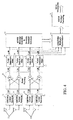
FIGURE 4 is a block diagram of an automatic dependent surveillance-broadcast (ADS-B) receiver system 20, which uses message decoding algorithms with long delay multipath mitigation and multiple antenna diversity reception to provide mitigation against short delay multipath. The system 20 includes a plurality ofantennas 22, withreceivers 26, abeam forming device 28, a plurality of pulse detection filters 29, adevice 30 that performs ADS-B burst detection on the plurality of diversity receivers, adevice 34 that cancels the interference due to long delay multipath on a selected diversity receiver output, and adevice 36 that performs message decoding. - Antenna space diversity is used to combat interference fading due to short delay multipath. Mode S transponder receivers that are also used to receive ADS-B messages employ top and bottom mounted omnidirectional antennas for diversity reception. Because these antennas are spaced in the vertical plane, they are most effective against multipath interference from ground reflections. However, multipath destructive interference (fading) due to reflections from other aircraft or structures on the airport surface is more severe than ground multipath fading. Multipath reflections from other aircraft and airport structures arrive from different azimuth directions. Thus, the system 20 includes
antennas 22 that are spaced horizontally on an aircraft (not shown) to provide diversity protection against this type of multipath. Minimum spacing between theantennas 22 is half a wavelength but it can be more. With a wavelength of 1090 MHz then the spacing is approximately 30 cm or 1 foot. - In one embodiment, the ADS-B receiver system 20 shares the
antennas 22 with a traffic collision avoidance system/airborne collision avoidance system (TCAS/ACAS). Diversity reception via the horizontally spacedantennas 22 protects against short-delay multipath destructive interference. - Consider the case of diversity reception using two antennas with omni-azimuth patterns. In this case the signals received by the two antennas, r'1(k) and r'2(k), are summed and subtracted to form two orthogonal sum and difference signals, r'Σ(k) and r'Δ(k) - see the
beam forming block 28. The sum and difference signals can be thought of as corresponding to signals received by two antennas that have azimuth antenna patterns given by
Sum Pattern:
Difference Pattern:
where s is the horizontal separation distance between the two antennas, ϕ is the azimuth angle of arrival of the signal and ϕ0 is the azimuth angle that the horizontal line through the two antennas makes with the direct line-of-sight path between the two aircraft. - From the two azimuth sum and difference gain factors, it can be seen that azimuth angles that result in peaks or nulls in one pattern will result in nulls or peaks in the other. Thus when the direct path and/or short delay multipath arrive from these directions, the signals combine differently and the probability that multipath and direct path cancel each other on both the sum and difference received signals is very small. However there are some azimuth angles for which both patterns have comparable gains. If both the direct path and the short delay multipath arrive at angles in which both patterns have comparable gains, then both sum and difference signals will be affected equally by the multipath and reception of an ADS-B message would be garbled regardless of whether the sum or difference signal is selected.
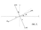
- To reduce the vulnerability to short delay multipath that arrives from directions where the sum and difference antenna pattern directions do not provide protection, additional antennas and receivers are needed so that patterns with fewer azimuth angles with comparable gains in all signal streams can be formed. For example, see
FIGURE 5 . - If such an antenna array of four elements were to be used to receive the ADS-B messages, the signals from the four antennas could be summed and subtracted to form two sets of sum and difference signals with azimuth antenna patterns given by
Sum (A1, A2) Pattern:
Difference (A1, A2) Pattern:
Sum (A3, A4) Pattern:
Difference (A3, A4) Pattern:
- In another embodiment, the four-element antenna array is split into two two-element arrays and one array is used as a top-mounted antenna and another as a bottom-mounted antenna. The signals from the top- and bottom-mounted antenna arrays are combined to form more complex antenna patterns with both azimuth and elevation antenna directivity that provide diversity protection against multipath from reflections from side structures as well as ground reflections. The
device 30 processes each of the outputs of thebeam forming device 28 to detect the reception of an ADS-B message and selects the output where the ADS-B message has been detected for long delay multipath cancellation and ADS-B message decoding. - The use of antenna pattern diversity does not provide protection against multipath with delay in the order of greater than the pulse duration. To protect against multipath with delays in the order of or longer than the pulse duration, the proposed ADS-B receiver employs the multipath mitigation techniques shown in the block diagram of
FIGURE 7 . - The
device 34 uses a data directed least-squares error multipath cancellation algorithm modified for use with the pulse position modulation employed for the transmission of ADS-B messages and a least-squares error algorithm to estimate the multipath channel gains from the known ADS-B message preamble data (pulses). -
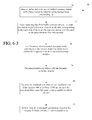
FIGURE 6-1 illustrates a flowchart of anexemplary process 40 performed by the system 20. First at ablock 42, ADS-B pulse signals are received at a plurality ofantennas 22 andlinear receivers 26. Next at ablock 44, mitigation of short delay multipath pulse signals is performed. Then at ablock 46, mitigation of long delay multipath pulse signals is performed. At ablock 48, an ADS-B message is generated. -
FIGURE 6-2 shows details of the step performed atblock 44. At ablock 54, antenna beams (i.e., antenna gain patterns) are formed with different azimuth patterns. Then at ablock 56, an attempt is made to detect preamble on each of the outputs of each beam by correlating the outputs of each antenna beam with the known pulse positions of the ADS-B message preamble. At ablock 58, the power at the output of each preamble correlator is calculated and simultaneously atblock 59 the frequency offset is also measured continuously. At ablock 60, each correlator output power is compared to a minimum power threshold and an indication is provided when the correlator output power exceeds the threshold. Simultaneously at ablock 61, the timing at which the correlator output power (pulse peak) is greatest is estimated and an indication is provided. At ablock 62, when a preamble is detected (preamble correlator output power exceeds minimum power threshold), the beam receiver output, the start-of-message, pulse-peak timing and the frequency offset measured at the pulse-peak are selected at ablock 62 for further processing. If the preamble is detected on one or more of the beam outputs, the beam output with the highest detected signal level and the corresponding pulse-peak timing and frequency offset are selected. -
FIGURE 6-3 shows details of the step performed atblock 46. At ablock 70, the sampled data outputs of each of the pulse detection filters for each of the antenna beams are stored in circular buffers large enough to hold an ADS-B message. When a preamble is detected, the data stored in the buffer corresponding to antenna beam selected inblock 62 is output for further processing at intervals equal to the pulse duration (one complex sample per pulse) starting at a time corresponding to the start-of-message and pulse-peak timing. At ablock 76, the frequency error/offset measured during preamble correlation on the selected beam is used to correct the frequency error in the received message samples. Next at ablock 78, the frequency-error corrected received samples are correlated with the known ADS-B message 4-pulse preamble sequence. Then at ablock 80, the preamble correlator outputs fromblock 78 are used to estimate the delay, amplitude and phase of each multipath component with delay equal to 500 ns, 1000 ns, 1500, ns, etc up to the maximum delay expected. And finally at ablock 82, the estimates of the amplitude and phase of multipath with discrete values of delay equal to multiples of the ADS-B pulse duration, i.e. 500 ns, 1000 ns, 1500 ns, etc, are used to cancel the interference from long delay multipath and estimate the amplitudes of the two possible pulse positions for each of the bits in the ADS-B message. -
FIGURE 6-4 shows details of the step performed atblock 82. At ablock 86, the estimated values for the multipath amplitude and phase for each of the discrete multipath delay values are used to make a first estimate of the pulse amplitudes for the two possible pulse positions (1 or 2) for all 112 bits in the ADS-B message from the 224 observed signal values received after the 4-pulse preamble sequence. Next at ablock 88, the estimated pulse amplitudes for the two possible pulse positions for the first bit (bit 1) and the two possible bit positions for last bit (bit 112) in the ADS-B message are compared to make pulse amplitude hard-decisions and calculate the confidence of the hard-decisions as follows. Forbit 1 andbit 112, the pulse position with the larger estimated pulse amplitude is assigned an amplitude hard-decision value of 1 and the pulse position with the smaller estimated pulse amplitude is assigned an amplitude hard-decision value of 0. The ratio of the pulse position with larger estimated amplitude to the pulse position with the smaller estimated amplitude is the confidence for the pulse amplitude hard-decisions. Next at ablock 89, the hard-decision pulse amplitudes for the two possible pulse positions forbits block 90, the step performed atblock 86 is repeated but only for the pulse amplitudes for the two possible pulse positions forbits 2 through 111. At ablock 92, pulse amplitude hard-decisions for the two possible pulse positions forbits block 88. Next at ablock 93, the pulse amplitude hard-decisions for the two possible pulse positions forbits pulses block 94, the steps atblocks block 96 the pulse amplitude hard-decisions for the two possible pulse positions for each of the 112 bits in the ADS-B message and the confidence of the hard-decisions are output to the ADS-B message decoding at ablock 48. - As illustrated in
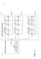
FIGURE 8-1 , when multipath with delays longer than an ADS-B pulse duration are present, the received signal r'(t) includes overlapped sequences of pulses (shown in different patterns), which make it difficult to detect the ADS-B message preamble 80. Therefore the present invention detects themessage preamble 80 in the presence of long-delay multipath by using a preamble correlation filter that looks for the unique 4 pulse preamble transmitted at the beginning of each ADS-B message (performed at 150 inFigure 7 ) and a pulse timing synchronization function that looks for the preamble pulse peaks (performed at 152 inFigure 7 ) on each of the outputs of an antenna beam former (performed at 28 inFigure 7 ) followed by a preamble detection and antenna beam selection function (performed at 160 inFigure 7 ). - The ADS-B receiver system 20 shown in
FIGURE 7 includes pulse detection filters 100, preamble correlation/detection filters 150, pulse-peak detection processing 152 and frequencyerror estimation processing 154 to simultaneously detect the ADS-B message preamble, estimate the frequency error between the transmitter and receiver and find the pulse peaks.FIGURE 7 also includesdata storage buffers 170 to store received data while searching for a preamble detection,frequency correction processing 172, multipath delay, amplitude andphase estimation processing 176 and pulse position amplitude estimation andmultipath cancellation processing 180 to be performed once a preamble has been detected. More detailed descriptions of the various processing blocks is provided in the following. - In one embodiment, the pulse detection filters are chosen to maximize the signal-to-noise ratio and reject interference from signals in adjacent channels. Because the center frequency of the ADS-B received signal is 1090 MHz ± 1 MHz, the pulse detection filters 100 have a bandwidth that is greater than the 2 MHz bandwidth of the ADS-B pulses. The pulse detection filters process the received data on both the sum and difference signal processing paths at a rate of N samples per pulse (2N samples per pulse period) where N ≥ 2.
- The pulse detection filters 100 are preceded by linear RF receiver
front end components 26 in each signal processing path and by the sum and difference beam former 28. The sum and difference outputs of the beam former 28, r'Σ(k) and r'Δ(k), include streams of samples received at a rate of at least N samples per pulse. - More detailed illustrations of one possible implementation of the preamble correlation/
detection filters 150, the pulse-peak detection processing 152 and the frequencyerror estimation processing 154 are shown inFIGURE 9 . The preamble detection filters 150 illustrated inFIGURE 9 perform a non-coherent correlation of the received signal samples output by the pulse detection filters 100, rΣ(k) or rΔ(k). Non-coherent correlation is necessary when the frequency error between the ADS-B transmitter and ADS-B receiver is greater than 200 kHz. An ADS-B message preamble is detected when the received preamble pulses "align with the taps" of the preamble correlation filters 150 and all 4 sum path correlator outputs Y'Σ(k), Y'Σ(k-2N), Y'Σ(k-7N) and Y'Σ(k-9N) or difference path correlator outputs Y'Δ(k), Y'Δ(k-2N), Y'Δ(k-7N) and Y'Δ(k-9N), exceed a minimum power threshold level. - The
pulse detection filter 100 outputs rΣ(k) or rΔ(k) are also used to compute the phase difference between the last two pulses in the preamble FΣ1(k) and FΔ1(k), between the last and second pulse FΣ2(k) and FΔ2(k), and between the last and first pulses in the preamble, FΣ3(k) or FΔ3(k). These phase differences are used to calculate the frequency error between the received preamble and the local "1090 MHz" receiver frequency at the instant of time when the preamble is detected and the pulse peak has been found. - The pulse-
peak detector 152 continuously computes the difference between power received in a time interval equal to the first half of a preamble pulse and the power received in the second half of a preamble pulse, DΣ(k) for the sum beam receive path and DΔ(k) for the difference beam receive path. The differences DΣ(k) and DΔ(k) can be computed by summing each difference over all 4 preamble pulses as shown inFIGURE 9 for DΣ(k) or it could be done only on one (first) of the pulses. The pulse peak is detected when the 4-pulse correlator outputs exceed the minimum power threshold and its corresponding difference between the power in the first half of the pulse and the second half of the pulse, DΣ(k) or DΔ(k), changes from positive to negative or vice versa, i.e. when it crosses the zero value. - When a preamble is detected and the pulse peak is detected in either the sum or difference receiver signal paths, diversity receiver
selection logic component 160 selects the signal stream for estimation of the channel long delay multipath, multipath cancellation, and ADS-B message decoding as described below and the data samples from the other receiver are discarded. If a preamble is detected in both the sum and difference receiver signal paths, then the receiver signal path with highest signal strength is selected. - Long Delay Multipath Amplitude and Phase Estimation: The algorithm for the estimation of the amplitude and phase of multipath with delay equal to a pulse duration or longer, as well as the multipath interference cancellation and data decoding algorithms are suitable for implementation after the received signal has been digitized. In addition it should be noted that once synchronization with the peaks of the direct path preamble pulses has been achieved, the position of the received data pulses need only be estimated at intervals equal to the pulse duration, T = 0.5 µs. And therefore the delays of the multipath need only have a resolution equal to the pulse interval also.
FIGURE 10 shows the pre-processing of the data that is stored in thedata storage buffers 170 before performing estimation of the amplitude and phase of the multipath at the delay intervals equal to the pulse duration. Each data storage buffer can be thought of as a two dimensional circular buffer where the number of columns is equal to the number of samples per pulse N and the number of rows is equal to twice the number of pulse positions between the first preamble pulse and the first message pulse, i.e. 16, plus twice the number of bits in the ADS-B message, i.e. 224, plus the maximum expected multipath delay in multiples of the pulse duration, e.g. 6. Data is stored one row at time. When a preamble is detected, the diversity receiver selection logic processing inblock 160 inFIGURE 9 provides a receiver select pointer to thebuffer 170 corresponding to the received data to be processed. This receiver select pointer is used inblock 182 to connect the buffer data output to the frequency offsetcorrection processing block 172. Diversity receiver selectionlogic processing block 160 provides a second pointer to the row in the selectedbuffer 170 where data samples for the first preamble pulse is stored (row 1) and a pointer to the column corresponding to the pulse peak. Data to be processed is then read out of the selected buffer column corresponding to the pulse peak. The frequency offset correction processing block uses the frequency correction provided by the diversity receiver selectionlogic processing block 160 to remove the frequency offset between transmitter and receiver and provide this data to the multipath delay, amplitude andphase estimation block 176. - In order to be able to estimate whether a received ADS-B message is corrupted by multipath, it is necessary to have a mathematical model (see
FIGURE 8-2 ) of the relationship between the frequency corrected received samples at intervals equal to the pulse duration, rp(i). This model is to be used to estimate the direct path and multipath amplitude and phases, h(0) and h(1) through h(M), and the amplitudes of the preamble, p(i), and data, a(i), pulses. - The frequency error between transmitter and receiver must be removed prior to the multipath channel complex gains estimation because the algorithm for the estimation of the pulse positions assumes that the amplitude and phase of each of the multipath components are constant throughout the message. Any frequency error will show up as a constant phase in the multipath estimates obtained from the preamble processing described in this section.
- More specifically, it is assumed that the down-sampled and frequency corrected pulse matched filter outputs samples rp(0), rp(1), rp(2), ... rp(9), corresponding to the preamble pulse peaks associated with the direct line-of-sight path (LOS) are related to the preamble pulse amplitudes p(0), p(1), ... p(9) by the mathematical representation:

- where the index i = 0 represents the timing of the pulse peak associated with the reception of the first preamble pulse and the index i = 9 represents the timing of the pulse peak associated with the last (fourth) preamble pulse received via the direct LOS path, and the precursor pulse values p(-1), p(-2), ... p(-M) are all assumed to be 0. The n(i) represent the receiver noise samples and h(0) through h(M) are complex gain (amplitude and phase) factors that represent the relative amplitudes of the direct path and multipath. Note that the direct path and multipath amplitude and phases h(0) through h(M) include the transmitter pulse response and receiver pulse matched filter response. The parameter M is the maximum multipath delay expected as a multiple of 0.5 µs. It is assumed that M ≤ 6, i.e., longest multipath delay is less than 3 µs.
- Since the preamble pulse amplitudes are known, the direct path and multipath complex gain factors are estimated by minimizing the sum of squared errors between the received samples rp(i) and estimates of the received samples, i.e.,

- where minimization is over the unknown multipath complex gains h'(0) through h'(M).
- It can be shown that this minimization problem reduces to solving the set of coupled linear equations


where
h' is an (M+1)x1 vector of the estimates of the unknown multipath complex gain factors, i.e.,
zp is a column vector with (M+1) elements that represent the cross-correlation between the frequency corrected received samples and a replica of the preamble pulse sequence, i.e.
where
- P is an (M+1)x(M+1) preamble correlation matrix with elements pnm given by

- From Eq. 14, it should be noted that zp(0) represents the output of the preamble matched
filter 186 shown inFIGURE 11 when the peaks of the preamble pulses received via the direct LOS path line up with the preamble matched filter taps, i.e., when the preamble detection is accomplished. - And the zp(1) through zp(M) are the next M frequency error compensated preamble matched filter outputs at the pulse interval.
- The estimates of the multipath complex gain factors can be computed as

- where V= P-1 is the inverse of the preamble correlation matrix. Also note that the inverse of the preamble correlation matrix can be pre computed and stored, making the computation of the multipath complex gains a straight forward and simple waited sum of the preamble matched
filter outputs 188 shown inFIGURE 11 . - As an example, the preamble correlation matrix P and its inverse P-1 = V for M = 3 when there is no overlap between the first and second pair of pulses in the preamble is given below.

- In this case, the estimation of the multipath complex gains is relatively simple.
- If the longest multipath delay expected results in overlap between the first pair of pulses in the preamble and the second pair of pulses, the calculation of the multipath complex gains is more complex and needs to remove the interference between preamble pulses. To illustrate this case, the preamble correlation matrix P and its inverse P-1 = V for M = 5 are shown below

- ADS-B Message Decoding with Long Delay Multipath Interference Cancellation: The multipath amplitude, phase and delay information obtained from the preamble is used to estimate the amplitudes of the pulses in the data portion of the ADS-message when multipath with delay in order of or longer than the pulse duration is interleaved or overlapped with the LOS pulses. The data pulse amplitude estimation in the presence of multipath is performed by processing the frequency error corrected pulse detection filter outputs samples that follow the detected preamble, i.e., rp(16), rp(17), rp(18), ... rp(L+M-1) as follows.
- The total number of samples used L+M is equal to twice the number of bits in the ADS-B message (L = 2
times 112 bits) because each bit is received in one of two possible pulse positions plus a number samples equal to the longest multipath delay expected M. This implies that all of the pulse detection filter outputs for the ADS-B message plus M additional samples must be stored before processing can begin. The frequency error corrected pulse detection filter outputs rp(16), rp(17), rp(18), ... rp(L+M-1) corresponding to the possible data pulse peak positions associated with the direct line-of-sight (LOS) path are related to the data pulse amplitudes a(0), a(1), ... a(L-1) by the following set of equations
- Each row in Eq. 17 is represented mathematically as

where the index i = 0 represents the timing of the pulse peak associated with the possible position of the first data pulse and the index i = L-1 represents the timing of the pulse peak associated with the last possible data pulse position received via the direct LOS path. The index i = L through L+M-1 represents the timing of the pulse positions associated with multipath that arrives after the last LOS data pulse. - The parameter M is the maximum multipath delay expected as a multiple of 0.5 µs. It is assumed that M ≤ 6, i.e., longest multipath delay is less than 3 µs.
- The precursor pulse position values a(-1), a(-2), ... a(-M) are all assumed to be 0 because no data pulses are transmitted between the last preamble pulse and the first data pulse.
- The n(i) represent the receiver noise samples and h(0) through h(M) are complex gain (amplitude and phase) factors that represent the relative amplitudes of the direct path and multipath estimated from the preamble pulses. Note the magnitude of h(0) is the absolute amplitude of the pulse received via the LOS path.
- The pulse amplitudes a(0), a(1), ... a(L-2)a(L-1) can take on the
value - Eq. 17 represents L+M equations with L unknowns which can be solved by minimizing the sum of squared errors between the frequency corrected received samples rp(16+i) and estimates of the received samples, i.e.,

where minimization is over the unknown pulse amplitude estimates a'(0) through a'(L-1). The prime notation is used to indicate that a'(0) through a'(L-1) are estimates and to differentiate them from the actual transmitted pulse amplitudes a(0) through a(L-1). - Eq. 19 can be written in matrix form as

where * denotes complex conjugate and t is the vector or matrix transpose operator, H is a (L+M) x L matrix of multipath complex gains given by
and where a' L and rp are column vectors with L and L +M elements respectively,

- Minimization with respect to the vector a' yields the matrix equation


where the matrix product H*t H = R*L is the complex conjugate of a L x L correlation matrix of the multipath complex gains given by
and where the elements of RL are given by

- The elements of the column vector gL t = [g(0), g(1), ..., g(L-1)] are given by

- which represent the outputs of a filter whose inputs are the received samples at intervals equal to the pulse position intervals and whose taps (coefficients) are the complex conjugates of the multipath complex gain factors h(0) through h(M). Thus the vector gL can be thought of as the output of a RAKE multipath combiner matched filter.
- Solving Eq. 24 for the unknown vector a'L, it can be seen that the optimum estimates of the pulse amplitudes are given by

where each row of the multipath correlation matrix inverse (R*L)-1 can be thought of as the weights of a linear equalizer filter which removes the multipath interference at the output of a RAKE matched filter receiver. The weights, i.e., the rows, vary as the received samples are passed through the linear equalizer because the interference depends on the previous data. Thus, the pulse position estimates are the cascade of a RAKE filter that combines the multipath coherently to maximize the signal energy and a filter that removes the interference from preceding pulses. - The matrix H and the vector rp are both known so one should in principle be able to calculate the optimum estimates of the pulse amplitudes from Eq. 30. However, inversion of R*L is not straightforward as this matrix inverse cannot be calculated and pre-stored as was the case for the preamble correlation matrix since the multipath correlation differs for each received message. Therefore, in order to solve Eq. 24, 25 for the vector of pulse amplitudes a'L a recursive method is used for solving the set of coupled simultaneous equations of the form described in Eq. 24, 25 known as the Levinson algorithm.
- To apply the Levinson algorithm it is necessary to reverse the order of the simultaneous

where

and where the superscript r denotes the order reverse. Eq. 31 can be solved recursively by using the following relationships


- Note that the first index j in Eq. 37-39 refers to the pulse position and the second index k refers to the step in the recursion. The final values in Eq. 37 and Eq. 38 are the estimates of the pulse amplitudes a'(0) through a'(L-1).
- Pulse Amplitude Hard-decisions and Multipath cancellation:
- Because ADS-B uses pulse position modulation to transmit a pulse in only one of two possible pulse positions, for each pair of amplitudes a'(i) and a'(i+1) where the index i is even, one of the pulse positions should have
amplitude 1 and the other should be 0. So for each pulse position pair the amplitude of the pulse position with the larger amplitude is set to 1 and the amplitude of the pulse position with the smaller amplitude is set to 0. These are called the hard-decision pulse amplitudes a†(i) and a†(i+1). - The hard decision pulse amplitudes for each pulse position should not be confused with the ADS-B message bit hard-decisions which are set based on whether the pulse with
amplitude 1 is inpulse position 1 orpulse position 2. Note also that the absolute value of the received pulse signal strength is given by the magnitude squared of the channel gains h(0) through h(M). So setting the a†(i) to 1 does not discard any information regarding the variability in received signal strength. - More specifically,
- For i even,
- If |a'(i)| < |a'(i+1)|, set a†(i) = 0 & a†(i+1) = 1,
- Otherwise, if |a'(i)| > |a'(i+1)|, set a†(i) = 1 & a†(i+1) = 0,
- Improved estimates for the pulse amplitudes a'(2) through a'(L-3) can be obtained by subtracting the hard-decisions a†(0), a†(1), a†(L-2) and a†(L-1) from the frequency corrected received data samples rp(16+i) and re-estimating the pulse amplitudes a'(2) through a'(L-3) by applying the Levinson algorithm again. This would be analogous to decision feedback equalization where weighted hard-decisions are fed back to remove the multipath interference prior to making a decision on the following data.
- The new set of equations that must be solved are expressed in matrix form as

where

with the p(n) given by Eq. 27, 28. - The elements of the column vector (gL-4)t = [g(2), g(3), ..., g(L-3)] are given by

where the cL-4 (n) are the received samples minus the hard decisions for the first two and last two pulse amplitudes weighted by the multipath complex gain factors, i.e.,
- Eq. 40 is also solved using the Levinson algorithm given in
Equations 34 through 39. However, this time only the elements of the column vectors gL-4 and a'L-4 given in Eq. 43, Eq. 44, and Equations 37 through 39 should be recomputed. The elements of the correlation matrix RL-4 defined in Eq. 27, 28 and the recursion factors β(j, k) in Eq. 34, 35 do not change and should be stored after the first pass through the Levinson algorithm. The hard-decisions for a†(2), a†(3), at(L-4) and a†(L-3) are then saved and output after the second pass along with the confidence measure c(2) forbit interval 2 and c(111) for bit interval (L-2)/2 = 111 and the procedure is repeated until pulse position hard decision amplitudes and confidence measures for all the bit intervals are obtained four at a time. - Pulse Position Bit Demodulation:
- The pulse amplitude hard-decisions a†(0), a†(1), ..., a†(L-2) and a†(L-1) that correspond to a pulse position where it has been decided that no pulse has been "received" after multipath cancellation are set to "0" while the pulse amplitude hard decisions that correspond to a pulse position where a pulse has been received are set to "1". The pulse amplitudes are then used to make a decision as to whether a "0" bit or "1" bit has been transmitted by taking the pulse amplitude hard decisions in pairs and making a bit decision based on whether the "1" pulse amplitude occupies the even or the odd pulse position. The bits decisions d(1), d(2), ..., d(L/2) and the confidence measures c(1), c(2), ..., c(L/2) are the output of the pulse position demodulator and serve as the input to the ADS-B message decoder.
- While the preferred embodiment of the invention has been illustrated and described, as noted above, many changes can be made without departing from the spirit and scope of the invention. Accordingly, the scope of the invention is not limited by the disclosure of the preferred embodiment. Instead, the invention should be determined entirely by reference to the claims that follow.
- The embodiments of the invention in which an exclusive property or privilege is claimed are defined as follows:
Claims (10)
- A method comprising:at a plurality of receivers (26),
receiving a plurality of signals from a plurality of diversity antennas (22);at a device (30) in communication with the plurality of receivers,
simultaneously processing the plurality of signals to detect the reception of an ADS-B message in the presence of short delay and long delay multipath signals to produce a signal that is free of interference from the short delay multipath signals;
removing interference from the long delay multipath signals from the produced signal; and
outputting an ADS-B message based on the produced signal that is free of short delay interference signals with the removed interference from long delay multipath signals. - The method of Claim 1, wherein the plurality of diversity antennas comprise antennas configure to receive signals at 1090 MHz, wherein the diversity antennas comprise a first pair of horizontally spaced antennas and simultaneous processing of the signals received by these two antennas comprises:summing the signals received from first and second horizontally separated antennas to create a first sum signal;subtracting the signals received from the first and second antennas to create a first difference signal; andsimultaneously processing the first sum and difference signals to detect the reception of an ADS-B message in the presence of short delay and long delay multipath signals, wherein the diversity antennas comprise a second pair of antennas spaced horizontally in a plane perpendicular to the plane of the first pair of antennas and simultaneous processing of the signals received by this second pair of antennas comprises:summing the signals received from third and fourth horizontally separated antennas to create a second sum signal;subtracting the signals received from the third and fourth antennas to create a second difference signal; andsimultaneously processing the plurality of signals to detect the reception of an ADS-B message in the presence of short delay and long delay multipath signals.
- The method of Claim 2, wherein the plurality of signals comprise automatic dependent surveillance-broadcast (ADS-B) signals, wherein the first and second antennas are vertically separated from the third and fourth antennas, wherein the horizontal separation is approximately at least half of the wavelength of the ADS-B signals.
- The method of Claim 3, wherein the first and second antennas are horizontally and vertically separated and the second and fourth antennas are horizontally and vertically separated.
- The method of Claim 3, wherein outputting the ADS-B message in the presence of short delay and long delay multipath signals comprises:performing preamble correlation for each of the first and second sum signals and first and second difference signals based on a previously known ADS-B message preamble configuration;selecting one of the first and second sum and difference signals with associated start-of-message value, pulse-peak timing value and frequency offset value based on the performed preamble correlation and a predefined power threshold; andstoring each of the first and second sum and difference signals in a buffer, and
wherein removing the interference from long delay multipath signals comprises:retrieving one of the stored sum and difference signals based on the selected signal;correcting a frequency error of the retrieved signal based on a frequency offset value associated with the selected signal;correlating the frequency error corrected signal with the previously known ADS-B message preamble configuration;estimating the amplitude and phase of the multipath signals at delay intervals of 500 ns based on the output of the correlation between the frequency error corrected selected signal with the known ADS-B preamble configuration that precedes the ADS-B message bits; andcancelling any corruption of the ADS-B message bits that follow the preamble by long delay multipath signal interference based on the estimated amplitude and phase of multipath signals at delay intervals of 500 ns. - A system comprising:a plurality of diversity antennas (22) configured to receive a plurality of signals;a plurality of receivers (26) configured to receive the plurality of signals from the plurality of diversity antennas;a device (30) in communication with the plurality of receivers, the device configured to:simultaneously process the plurality of signals to detect the reception of an ADS-B message in the presence of short delay and long delay multipath signals to produce a signal that is free of interference from the short delay multipath signals;remove interference from the long delay multipath signals from the produced signal; andoutput an ADS-B message based on the produced signal that is free of short delay interference signals with the removed interference from long delay multipath signals.
- The system of Claim 6, wherein the plurality of diversity antennas comprise antennas configure to receive signals at 1090 MHz, wherein the diversity antennas comprise a first pair of horizontally spaced antennas and the device simultaneous processes by:summing the signals received from first and second horizontally separated antennas to create a first sum signal;subtracting the signals received from the first and second antennas to create a first difference signal; andsimultaneously processing the first sum and difference signals to detect the reception of an ADS-B message in the presence of short delay and long delay multipath signals,
wherein the diversity antennas comprise a second pair of antennas spaced horizontally in a plane perpendicular to the plane of the first pair of antennas and the device simultaneous processes by:summing the signals received from third and fourth horizontally separated antennas to create a second sum signal;subtracting the signals received from the third and fourth antennas to create a second difference signal; andsimultaneously processing the plurality of signals to detect the reception of an ADS-B message in the presence of short delay and long delay multipath signals. - The system of Claim 7, wherein the plurality of signals comprise automatic dependent surveillance-broadcast (ADS-B) signals, wherein the first and second antennas are vertically separated from the third and fourth antennas, wherein the horizontal separation is approximately at least half of the wavelength of the ADS-B signals.
- The system of Claim 7, wherein the first and second antennas are horizontally and vertically separated and the second and fourth antennas are horizontally and vertically separated.
- The system of Claim 7, wherein the device outputs the ADS-B message in the presence of short delay and long delay multipath signals by:performing preamble correlation for each of the first and second sum signals and first and second difference signals based on a previously known ADS-B message preamble configuration;selecting one of the first and second sum and difference signals with associated start-of-message value, pulse-peak timing value and frequency offset value based on the performed preamble correlation and a predefined power threshold; andstoring each of the first and second sum and difference signals in a buffer, and
wherein the device removes the interference from long delay multipath signals by:retrieving one of the stored sum and difference signals based on the selected signal;correcting a frequency error of the retrieved signal based on a frequency offset value associated with the selected signal;correlating the frequency error corrected signal with the previously known ADS-B message preamble configuration;estimating the amplitude and phase of the multipath signals at delay intervals of 500 ns based on the output of the correlation between the frequency error corrected selected signal with the known ADS-B preamble configuration that precedes the ADS-B message bits; andcancelling any corruption of the ADS-B message bits that follow the preamble by long delay multipath signal interference based on the estimated amplitude and phase of multipath signals at delay intervals of 500 ns.
Applications Claiming Priority (1)
| Application Number | Priority Date | Filing Date | Title |
|---|---|---|---|
| US13/250,003 US8917201B2 (en) | 2011-09-30 | 2011-09-30 | ADS-B receiver system with multipath mitigation |
Publications (3)
| Publication Number | Publication Date |
|---|---|
| EP2575270A2 true EP2575270A2 (en) | 2013-04-03 |
| EP2575270A3 EP2575270A3 (en) | 2014-10-01 |
| EP2575270B1 EP2575270B1 (en) | 2016-06-01 |
Family
ID=47351368
Family Applications (1)
| Application Number | Title | Priority Date | Filing Date |
|---|---|---|---|
| EP12186196.7A Not-in-force EP2575270B1 (en) | 2011-09-30 | 2012-09-26 | ADS-B receiver system with multipath mitigation |
Country Status (3)
| Country | Link |
|---|---|
| US (1) | US8917201B2 (en) |
| EP (1) | EP2575270B1 (en) |
| CN (1) | CN103124184A (en) |
Cited By (1)
| Publication number | Priority date | Publication date | Assignee | Title |
|---|---|---|---|---|
| CN108475065A (en) * | 2017-06-30 | 2018-08-31 | 深圳市大疆创新科技有限公司 | Method of controlling security, equipment and the machine readable storage medium of unmanned plane during flying |
Families Citing this family (24)
| Publication number | Priority date | Publication date | Assignee | Title |
|---|---|---|---|---|
| KR101769809B1 (en) * | 2011-10-25 | 2017-08-22 | 삼성전자주식회사 | Method of detecting symbol by combining survived path in receiver including multiple reception antennas |
| GB2502279B (en) | 2012-05-21 | 2014-07-09 | Aceaxis Ltd | Reduction of intermodulation products |
| US8767815B2 (en) * | 2012-11-30 | 2014-07-01 | Honeywell International Inc. | Parallel-frequency partially-coherent reception of pulse-position modulated ADS-B messages |
| CN103441768B (en) * | 2013-08-16 | 2015-05-13 | 宁波成电泰克电子信息技术发展有限公司 | ADS-B signal processing method |
| US9686382B2 (en) | 2014-08-04 | 2017-06-20 | Honeywell International Inc. | Double decoder system for decoding overlapping aircraft surveillance signals |
| US9766331B2 (en) | 2014-12-16 | 2017-09-19 | Honeywell International Inc. | Sectorized antennas for improved airborne reception of surveillance signals |
| CN104579413B (en) * | 2015-01-06 | 2018-05-11 | 中电科航空电子有限公司 | A kind of comprehensive radio frequency system |
| CN104579391A (en) * | 2015-02-06 | 2015-04-29 | 合肥戎科信息技术开发有限公司 | Ads-b receiver module |
| US10236955B2 (en) | 2016-02-19 | 2019-03-19 | Elwha Llc | System with transmitter and receiver remote from one another and configured to provide a channel capacity that exceeds a saturation channel capacity |
| US9800310B2 (en) * | 2016-02-19 | 2017-10-24 | Elwha Llc | Transmitter configured to provide a channel capacity that exceeds a saturation channel capacity |
| US10236947B2 (en) | 2016-02-19 | 2019-03-19 | Elwha Llc | System with transmitter and receiver configured to provide a channel capacity that exceeds a saturation channel capacity |
| US9780853B2 (en) * | 2016-02-19 | 2017-10-03 | Elwha Llc | Receiver configured to provide a channel capacity that exceeds a saturation channel capacity |
| US10650689B2 (en) | 2016-11-01 | 2020-05-12 | The Mitre Corporation | Waveform authentication system and method |
| WO2018121437A1 (en) * | 2016-12-26 | 2018-07-05 | 华为技术有限公司 | Method for determining candidate line-of-sight path, and wireless local area network device |
| US10116374B2 (en) | 2017-03-17 | 2018-10-30 | Aieron LLC | Receiver with non-coherent matched filter |
| US9992011B1 (en) * | 2017-03-17 | 2018-06-05 | Aireon Llc | Receiver with coherent matched filter |
| EP3616372B1 (en) * | 2017-04-28 | 2022-08-31 | Telefonaktiebolaget LM Ericsson (Publ) | Base transceiver station interference cancellation for reuse of terrestrial carrier in air-to-ground communication |
| FR3067189B1 (en) * | 2017-06-01 | 2020-06-12 | Continental Automotive France | METHOD FOR THE SPATIAL AND TIME SUPPRESSION OF MULTI-PATH INTERFERENCE FOR A FREQUENCY MODULATED RADIO SIGNAL RECEIVER |
| CN107817464A (en) * | 2017-11-21 | 2018-03-20 | 王晨 | A kind of anti-interference anti-deception ADS B receivers and its method of reseptance based on directional aerial |
| CN109905161A (en) * | 2017-12-08 | 2019-06-18 | 中电科特种飞机系统工程有限公司 | A kind of data transmission system, method and the medium of portable ADS-B |
| CN110162854B (en) * | 2019-05-09 | 2023-05-26 | 重庆大学 | High-speed self-adaptive decision feedback equalizer |
| CN110855397B (en) * | 2019-11-07 | 2023-03-28 | 中国民航大学 | ADS-B delay forwarding message detection and jamming station positioning method |
| US11240069B2 (en) * | 2020-01-31 | 2022-02-01 | Kabushiki Kaisha Tokai Rika Denki Seisakusho | Communication device, information processing method, and storage medium |
| US11703565B2 (en) | 2020-03-30 | 2023-07-18 | Raytheon Company | Methods and apparatus for identifying and preventing tracking of false primary target reports |
Family Cites Families (16)
| Publication number | Priority date | Publication date | Assignee | Title |
|---|---|---|---|---|
| US5144315A (en) * | 1989-02-10 | 1992-09-01 | Cardion, Inc. | System for accurately monitoring aircraft position during training exercises |
| US5107268A (en) * | 1990-09-20 | 1992-04-21 | Honeywell Inc. | Method of multipath track reduction in an aircraft tracking system |
| US5448243A (en) * | 1991-12-30 | 1995-09-05 | Deutsche Forschungsanstalt Fur Luft- Und Raumfahrt E.V. | System for locating a plurality of objects and obstructions and for detecting and determining the rolling status of moving objects, such as aircraft, ground vehicles, and the like |
| US5317323A (en) * | 1993-03-05 | 1994-05-31 | E-Systems, Inc. | Passive high accuracy geolocation system and method |
| US5528244A (en) * | 1995-03-31 | 1996-06-18 | Cardion, Inc. | Processing for mode S signals suffering multipath distortion |
| US6633259B1 (en) * | 1999-03-05 | 2003-10-14 | Rannuch Corporation | Method and apparatus for improving utility of automatic dependent surveillance |
| FR2794459B1 (en) | 1999-05-19 | 2004-09-03 | Atofina | POLYALCOXYAMINES FROM BETA-SUBSTITUTED NITROXIDES |
| US6469654B1 (en) * | 2000-05-09 | 2002-10-22 | Advanced Navigation & Positioning Corp. | Transponder landing system |
| US6792058B1 (en) | 2000-07-12 | 2004-09-14 | Lockheed Martin Corporation | Digital receiving system for dense environment of aircraft |
| US6670909B2 (en) * | 2001-01-16 | 2003-12-30 | Time Domain Corporation | Ultra-wideband smart sensor interface network and method |
| US20060148429A1 (en) * | 2002-12-24 | 2006-07-06 | Matsushita Electric Industrial Co., Ltd. | Transmission path simulation method and transmission path simulator |
| AU2003901463A0 (en) * | 2003-03-31 | 2003-04-17 | Qx Corporation Pty Ltd | A method and device for multipath mitigation in positioning systems using clustered positioning signals |
| FR2860882B1 (en) * | 2003-10-10 | 2006-02-03 | Thales Sa | METHOD FOR PRE-DETECTING RESPONSES IN SECONDARY RADAR AND APPLICATION TO DETECTION OF S MODE RESPONSES |
| FR2909772B1 (en) * | 2006-12-12 | 2012-12-21 | Thales Sa | METHOD OF REDUCING MULPOSRATE PROPAGATION EFFECTS WHEN PROCESSING "S" MODE RESPONSES |
| FR2909773B1 (en) * | 2006-12-12 | 2009-01-30 | Thales Sa | MULTIVOYAL PASSIVE RADAR PROCESSING METHOD OF FM OPPORTUNITY SIGNAL. |
| DE102008059424B4 (en) | 2008-11-27 | 2023-01-19 | IAD Gesellschaft für Informatik, Automatisierung und Datenverarbeitung mbH | Secondary radar system with dynamic sectorization of the space to be monitored using multi-antenna arrangements and methods for this |
-
2011
- 2011-09-30 US US13/250,003 patent/US8917201B2/en active Active
-
2012
- 2012-09-26 EP EP12186196.7A patent/EP2575270B1/en not_active Not-in-force
- 2012-09-29 CN CN2012105957227A patent/CN103124184A/en active Pending
Non-Patent Citations (1)
| Title |
|---|
| None |
Cited By (1)
| Publication number | Priority date | Publication date | Assignee | Title |
|---|---|---|---|---|
| CN108475065A (en) * | 2017-06-30 | 2018-08-31 | 深圳市大疆创新科技有限公司 | Method of controlling security, equipment and the machine readable storage medium of unmanned plane during flying |
Also Published As
| Publication number | Publication date |
|---|---|
| US20130082867A1 (en) | 2013-04-04 |
| EP2575270B1 (en) | 2016-06-01 |
| CN103124184A (en) | 2013-05-29 |
| US8917201B2 (en) | 2014-12-23 |
| EP2575270A3 (en) | 2014-10-01 |
Similar Documents
| Publication | Publication Date | Title |
|---|---|---|
| EP2575270B1 (en) | ADS-B receiver system with multipath mitigation | |
| US6173014B1 (en) | Method of and apparatus for interference rejection combining and downlink beamforming in a cellular radio communications system | |
| EP1205007B1 (en) | Method of and apparatus for beam reduction and combining in a radio communications system | |
| EP1135908B8 (en) | Adaptive channel characterization using decoded symbols | |
| CN101533091B (en) | Space-time two-dimensional narrow band barrage jamming method | |
| JP2002508129A (en) | Interpreting received signals | |
| US8022860B1 (en) | Enchanced interference cancellation and telemetry reception in multipath environments with a single paraboic dish antenna using a focal plane array | |
| US20030214881A1 (en) | Underwater telemetry apparatus and method | |
| Petrus | Novel adaptive array algorithms and their impact on cellular system capacity | |
| CA2740754A1 (en) | Satellite telecommunication system comprising a mechanism for separating messages transmitted by a plurality of transmitters | |
| US7315589B2 (en) | Apparatus and method for selecting optimal beam for digital TV receiver | |
| US10880678B1 (en) | Indoor and outdoor geolocation and time of arrival estimation | |
| EP2281325A1 (en) | A process for minimising jammer noise in receiver systems | |
| Zemmari | Reference signal extraction for GSM passive coherent location | |
| Reck et al. | Spatial filtering and equalization for SSR signal detection in a multipath environment | |
| US20230101372A1 (en) | Interference and jammer cancellation for radios | |
| EP1038364B1 (en) | Apparatus and methods for determining signal direction from an estimated signal medium response for a ray component of a radio signal | |
| Grotz et al. | Signal detection and synchronization for interference overloaded satellite broadcast reception | |
| KR100583240B1 (en) | Optimal beam selection method for improving digital broadcasting reception performance, and digital broadcasting receiving apparatus | |
| JP2005354677A (en) | Path searcher and path searching method | |
| JP2013038637A (en) | Receiving device and receiving method | |
| KR100540170B1 (en) | Apparatus and method of digital tv receiver for beam-forming using direction of arrival estimation of main path signal | |
| Petri et al. | The effects of DVB-T SFN data on passive radar signal processing | |
| JP7378683B2 (en) | Wireless communication device and signal processing method | |
| Elkamchouchi et al. | Robust doa estimation and data detection for mobile communication in multipath environment |
Legal Events
| Date | Code | Title | Description |
|---|---|---|---|
| PUAI | Public reference made under article 153(3) epc to a published international application that has entered the european phase |
Free format text: ORIGINAL CODE: 0009012 |
|
| 17P | Request for examination filed |
Effective date: 20120926 |
|
| AK | Designated contracting states |
Kind code of ref document: A2 Designated state(s): AL AT BE BG CH CY CZ DE DK EE ES FI FR GB GR HR HU IE IS IT LI LT LU LV MC MK MT NL NO PL PT RO RS SE SI SK SM TR |
|
| AX | Request for extension of the european patent |
Extension state: BA ME |
|
| PUAL | Search report despatched |
Free format text: ORIGINAL CODE: 0009013 |
|
| AK | Designated contracting states |
Kind code of ref document: A3 Designated state(s): AL AT BE BG CH CY CZ DE DK EE ES FI FR GB GR HR HU IE IS IT LI LT LU LV MC MK MT NL NO PL PT RO RS SE SI SK SM TR |
|
| AX | Request for extension of the european patent |
Extension state: BA ME |
|
| RIC1 | Information provided on ipc code assigned before grant |
Ipc: H04B 7/02 20060101ALI20140827BHEP Ipc: H04B 7/08 20060101ALI20140827BHEP Ipc: H04B 7/06 20060101ALI20140827BHEP Ipc: G08G 5/00 20060101ALI20140827BHEP Ipc: H04B 1/10 20060101ALI20140827BHEP Ipc: H04B 7/185 20060101AFI20140827BHEP |
|
| 17Q | First examination report despatched |
Effective date: 20140925 |
|
| RAP1 | Party data changed (applicant data changed or rights of an application transferred) |
Owner name: HONEYWELL INTERNATIONAL INC. |
|
| GRAP | Despatch of communication of intention to grant a patent |
Free format text: ORIGINAL CODE: EPIDOSNIGR1 |
|
| INTG | Intention to grant announced |
Effective date: 20160125 |
|
| GRAS | Grant fee paid |
Free format text: ORIGINAL CODE: EPIDOSNIGR3 |
|
| GRAA | (expected) grant |
Free format text: ORIGINAL CODE: 0009210 |
|
| AK | Designated contracting states |
Kind code of ref document: B1 Designated state(s): AL AT BE BG CH CY CZ DE DK EE ES FI FR GB GR HR HU IE IS IT LI LT LU LV MC MK MT NL NO PL PT RO RS SE SI SK SM TR |
|
| REG | Reference to a national code |
Ref country code: GB Ref legal event code: FG4D |
|
| REG | Reference to a national code |
Ref country code: CH Ref legal event code: EP Ref country code: AT Ref legal event code: REF Ref document number: 804431 Country of ref document: AT Kind code of ref document: T Effective date: 20160615 |
|
| REG | Reference to a national code |
Ref country code: IE Ref legal event code: FG4D |
|
| REG | Reference to a national code |
Ref country code: DE Ref legal event code: R096 Ref document number: 602012019132 Country of ref document: DE |
|
| REG | Reference to a national code |
Ref country code: FR Ref legal event code: PLFP Year of fee payment: 5 |
|
| REG | Reference to a national code |
Ref country code: LT Ref legal event code: MG4D |
|
| REG | Reference to a national code |
Ref country code: NL Ref legal event code: MP Effective date: 20160601 |
|
| PG25 | Lapsed in a contracting state [announced via postgrant information from national office to epo] |
Ref country code: NO Free format text: LAPSE BECAUSE OF FAILURE TO SUBMIT A TRANSLATION OF THE DESCRIPTION OR TO PAY THE FEE WITHIN THE PRESCRIBED TIME-LIMIT Effective date: 20160901 Ref country code: FI Free format text: LAPSE BECAUSE OF FAILURE TO SUBMIT A TRANSLATION OF THE DESCRIPTION OR TO PAY THE FEE WITHIN THE PRESCRIBED TIME-LIMIT Effective date: 20160601 Ref country code: LT Free format text: LAPSE BECAUSE OF FAILURE TO SUBMIT A TRANSLATION OF THE DESCRIPTION OR TO PAY THE FEE WITHIN THE PRESCRIBED TIME-LIMIT Effective date: 20160601 |
|
| PGFP | Annual fee paid to national office [announced via postgrant information from national office to epo] |
Ref country code: GB Payment date: 20160830 Year of fee payment: 5 |
|
| REG | Reference to a national code |
Ref country code: AT Ref legal event code: MK05 Ref document number: 804431 Country of ref document: AT Kind code of ref document: T Effective date: 20160601 |
|
| PG25 | Lapsed in a contracting state [announced via postgrant information from national office to epo] |
Ref country code: HR Free format text: LAPSE BECAUSE OF FAILURE TO SUBMIT A TRANSLATION OF THE DESCRIPTION OR TO PAY THE FEE WITHIN THE PRESCRIBED TIME-LIMIT Effective date: 20160601 Ref country code: ES Free format text: LAPSE BECAUSE OF FAILURE TO SUBMIT A TRANSLATION OF THE DESCRIPTION OR TO PAY THE FEE WITHIN THE PRESCRIBED TIME-LIMIT Effective date: 20160601 Ref country code: SE Free format text: LAPSE BECAUSE OF FAILURE TO SUBMIT A TRANSLATION OF THE DESCRIPTION OR TO PAY THE FEE WITHIN THE PRESCRIBED TIME-LIMIT Effective date: 20160601 Ref country code: GR Free format text: LAPSE BECAUSE OF FAILURE TO SUBMIT A TRANSLATION OF THE DESCRIPTION OR TO PAY THE FEE WITHIN THE PRESCRIBED TIME-LIMIT Effective date: 20160902 Ref country code: LV Free format text: LAPSE BECAUSE OF FAILURE TO SUBMIT A TRANSLATION OF THE DESCRIPTION OR TO PAY THE FEE WITHIN THE PRESCRIBED TIME-LIMIT Effective date: 20160601 Ref country code: RS Free format text: LAPSE BECAUSE OF FAILURE TO SUBMIT A TRANSLATION OF THE DESCRIPTION OR TO PAY THE FEE WITHIN THE PRESCRIBED TIME-LIMIT Effective date: 20160601 Ref country code: NL Free format text: LAPSE BECAUSE OF FAILURE TO SUBMIT A TRANSLATION OF THE DESCRIPTION OR TO PAY THE FEE WITHIN THE PRESCRIBED TIME-LIMIT Effective date: 20160601 |
|
| PG25 | Lapsed in a contracting state [announced via postgrant information from national office to epo] |
Ref country code: EE Free format text: LAPSE BECAUSE OF FAILURE TO SUBMIT A TRANSLATION OF THE DESCRIPTION OR TO PAY THE FEE WITHIN THE PRESCRIBED TIME-LIMIT Effective date: 20160601 Ref country code: IT Free format text: LAPSE BECAUSE OF FAILURE TO SUBMIT A TRANSLATION OF THE DESCRIPTION OR TO PAY THE FEE WITHIN THE PRESCRIBED TIME-LIMIT Effective date: 20160601 Ref country code: CZ Free format text: LAPSE BECAUSE OF FAILURE TO SUBMIT A TRANSLATION OF THE DESCRIPTION OR TO PAY THE FEE WITHIN THE PRESCRIBED TIME-LIMIT Effective date: 20160601 Ref country code: SK Free format text: LAPSE BECAUSE OF FAILURE TO SUBMIT A TRANSLATION OF THE DESCRIPTION OR TO PAY THE FEE WITHIN THE PRESCRIBED TIME-LIMIT Effective date: 20160601 Ref country code: IS Free format text: LAPSE BECAUSE OF FAILURE TO SUBMIT A TRANSLATION OF THE DESCRIPTION OR TO PAY THE FEE WITHIN THE PRESCRIBED TIME-LIMIT Effective date: 20161001 Ref country code: RO Free format text: LAPSE BECAUSE OF FAILURE TO SUBMIT A TRANSLATION OF THE DESCRIPTION OR TO PAY THE FEE WITHIN THE PRESCRIBED TIME-LIMIT Effective date: 20160601 |
|
| PGFP | Annual fee paid to national office [announced via postgrant information from national office to epo] |
Ref country code: DE Payment date: 20160928 Year of fee payment: 5 |
|
| PG25 | Lapsed in a contracting state [announced via postgrant information from national office to epo] |
Ref country code: SM Free format text: LAPSE BECAUSE OF FAILURE TO SUBMIT A TRANSLATION OF THE DESCRIPTION OR TO PAY THE FEE WITHIN THE PRESCRIBED TIME-LIMIT Effective date: 20160601 Ref country code: PL Free format text: LAPSE BECAUSE OF FAILURE TO SUBMIT A TRANSLATION OF THE DESCRIPTION OR TO PAY THE FEE WITHIN THE PRESCRIBED TIME-LIMIT Effective date: 20160601 Ref country code: BE Free format text: LAPSE BECAUSE OF NON-PAYMENT OF DUE FEES Effective date: 20160601 Ref country code: AT Free format text: LAPSE BECAUSE OF FAILURE TO SUBMIT A TRANSLATION OF THE DESCRIPTION OR TO PAY THE FEE WITHIN THE PRESCRIBED TIME-LIMIT Effective date: 20160601 Ref country code: PT Free format text: LAPSE BECAUSE OF FAILURE TO SUBMIT A TRANSLATION OF THE DESCRIPTION OR TO PAY THE FEE WITHIN THE PRESCRIBED TIME-LIMIT Effective date: 20161003 |
|
| REG | Reference to a national code |
Ref country code: DE Ref legal event code: R097 Ref document number: 602012019132 Country of ref document: DE |
|
| PLBE | No opposition filed within time limit |
Free format text: ORIGINAL CODE: 0009261 |
|
| STAA | Information on the status of an ep patent application or granted ep patent |
Free format text: STATUS: NO OPPOSITION FILED WITHIN TIME LIMIT |
|
| PG25 | Lapsed in a contracting state [announced via postgrant information from national office to epo] |
Ref country code: MC Free format text: LAPSE BECAUSE OF FAILURE TO SUBMIT A TRANSLATION OF THE DESCRIPTION OR TO PAY THE FEE WITHIN THE PRESCRIBED TIME-LIMIT Effective date: 20160601 |
|
| REG | Reference to a national code |
Ref country code: CH Ref legal event code: PL |
|
| 26N | No opposition filed |
Effective date: 20170302 |
|
| PG25 | Lapsed in a contracting state [announced via postgrant information from national office to epo] |
Ref country code: DK Free format text: LAPSE BECAUSE OF FAILURE TO SUBMIT A TRANSLATION OF THE DESCRIPTION OR TO PAY THE FEE WITHIN THE PRESCRIBED TIME-LIMIT Effective date: 20160601 Ref country code: SI Free format text: LAPSE BECAUSE OF FAILURE TO SUBMIT A TRANSLATION OF THE DESCRIPTION OR TO PAY THE FEE WITHIN THE PRESCRIBED TIME-LIMIT Effective date: 20160601 |
|
| REG | Reference to a national code |
Ref country code: IE Ref legal event code: MM4A |
|
| PG25 | Lapsed in a contracting state [announced via postgrant information from national office to epo] |
Ref country code: IE Free format text: LAPSE BECAUSE OF NON-PAYMENT OF DUE FEES Effective date: 20160926 Ref country code: LI Free format text: LAPSE BECAUSE OF NON-PAYMENT OF DUE FEES Effective date: 20160930 Ref country code: CH Free format text: LAPSE BECAUSE OF NON-PAYMENT OF DUE FEES Effective date: 20160930 |
|
| PG25 | Lapsed in a contracting state [announced via postgrant information from national office to epo] |
Ref country code: LU Free format text: LAPSE BECAUSE OF NON-PAYMENT OF DUE FEES Effective date: 20160926 |
|
| REG | Reference to a national code |
Ref country code: FR Ref legal event code: PLFP Year of fee payment: 6 |
|
| REG | Reference to a national code |
Ref country code: DE Ref legal event code: R119 Ref document number: 602012019132 Country of ref document: DE |
|
| GBPC | Gb: european patent ceased through non-payment of renewal fee |
Effective date: 20170926 |
|
| PG25 | Lapsed in a contracting state [announced via postgrant information from national office to epo] |
Ref country code: CY Free format text: LAPSE BECAUSE OF FAILURE TO SUBMIT A TRANSLATION OF THE DESCRIPTION OR TO PAY THE FEE WITHIN THE PRESCRIBED TIME-LIMIT Effective date: 20160601 Ref country code: HU Free format text: LAPSE BECAUSE OF FAILURE TO SUBMIT A TRANSLATION OF THE DESCRIPTION OR TO PAY THE FEE WITHIN THE PRESCRIBED TIME-LIMIT; INVALID AB INITIO Effective date: 20120926 |
|
| PG25 | Lapsed in a contracting state [announced via postgrant information from national office to epo] |
Ref country code: TR Free format text: LAPSE BECAUSE OF FAILURE TO SUBMIT A TRANSLATION OF THE DESCRIPTION OR TO PAY THE FEE WITHIN THE PRESCRIBED TIME-LIMIT Effective date: 20160601 Ref country code: MT Free format text: LAPSE BECAUSE OF NON-PAYMENT OF DUE FEES Effective date: 20160930 Ref country code: MK Free format text: LAPSE BECAUSE OF FAILURE TO SUBMIT A TRANSLATION OF THE DESCRIPTION OR TO PAY THE FEE WITHIN THE PRESCRIBED TIME-LIMIT Effective date: 20160601 |
|
| PG25 | Lapsed in a contracting state [announced via postgrant information from national office to epo] |
Ref country code: BG Free format text: LAPSE BECAUSE OF FAILURE TO SUBMIT A TRANSLATION OF THE DESCRIPTION OR TO PAY THE FEE WITHIN THE PRESCRIBED TIME-LIMIT Effective date: 20160601 Ref country code: DE Free format text: LAPSE BECAUSE OF NON-PAYMENT OF DUE FEES Effective date: 20180404 Ref country code: GB Free format text: LAPSE BECAUSE OF NON-PAYMENT OF DUE FEES Effective date: 20170926 |
|
| REG | Reference to a national code |
Ref country code: FR Ref legal event code: PLFP Year of fee payment: 7 |
|
| PG25 | Lapsed in a contracting state [announced via postgrant information from national office to epo] |
Ref country code: AL Free format text: LAPSE BECAUSE OF FAILURE TO SUBMIT A TRANSLATION OF THE DESCRIPTION OR TO PAY THE FEE WITHIN THE PRESCRIBED TIME-LIMIT Effective date: 20160601 |
|
| PGFP | Annual fee paid to national office [announced via postgrant information from national office to epo] |
Ref country code: FR Payment date: 20190925 Year of fee payment: 8 |
|
| PG25 | Lapsed in a contracting state [announced via postgrant information from national office to epo] |
Ref country code: FR Free format text: LAPSE BECAUSE OF NON-PAYMENT OF DUE FEES Effective date: 20200930 |
|
| P01 | Opt-out of the competence of the unified patent court (upc) registered |
Effective date: 20230525 |