EP2575229A2 - Photovoltaikgeneratorsystem mit angeschlossenem Netz paralleler Wechselrichter - Google Patents
Photovoltaikgeneratorsystem mit angeschlossenem Netz paralleler Wechselrichter Download PDFInfo
- Publication number
- EP2575229A2 EP2575229A2 EP20110187245 EP11187245A EP2575229A2 EP 2575229 A2 EP2575229 A2 EP 2575229A2 EP 20110187245 EP20110187245 EP 20110187245 EP 11187245 A EP11187245 A EP 11187245A EP 2575229 A2 EP2575229 A2 EP 2575229A2
- Authority
- EP
- European Patent Office
- Prior art keywords
- photovoltaic
- photovoltaic generation
- generation system
- inverter
- electrical energy
- Prior art date
- Legal status (The legal status is an assumption and is not a legal conclusion. Google has not performed a legal analysis and makes no representation as to the accuracy of the status listed.)
- Pending
Links
Images




Classifications
-
- H—ELECTRICITY
- H02—GENERATION; CONVERSION OR DISTRIBUTION OF ELECTRIC POWER
- H02J—ELECTRIC POWER NETWORKS; CIRCUIT ARRANGEMENTS OR SYSTEMS FOR SUPPLYING OR DISTRIBUTING ELECTRIC POWER; SYSTEMS FOR STORING ELECTRIC ENERGY
- H02J7/00—Circuit arrangements for charging or discharging batteries or for supplying loads from batteries
- H02J7/34—Parallel operation in networks using both storage and other DC sources, e.g. providing buffering
- H02J7/35—Parallel operation in networks using both storage and other DC sources, e.g. providing buffering with light sensitive cells
-
- H—ELECTRICITY
- H10—SEMICONDUCTOR DEVICES; ELECTRIC SOLID-STATE DEVICES NOT OTHERWISE PROVIDED FOR
- H10F—INORGANIC SEMICONDUCTOR DEVICES SENSITIVE TO INFRARED RADIATION, LIGHT, ELECTROMAGNETIC RADIATION OF SHORTER WAVELENGTH OR CORPUSCULAR RADIATION
- H10F77/00—Constructional details of devices covered by this subclass
- H10F77/95—Circuit arrangements
- H10F77/953—Circuit arrangements for devices having potential barriers
- H10F77/955—Circuit arrangements for devices having potential barriers for photovoltaic devices
-
- H—ELECTRICITY
- H02—GENERATION; CONVERSION OR DISTRIBUTION OF ELECTRIC POWER
- H02J—ELECTRIC POWER NETWORKS; CIRCUIT ARRANGEMENTS OR SYSTEMS FOR SUPPLYING OR DISTRIBUTING ELECTRIC POWER; SYSTEMS FOR STORING ELECTRIC ENERGY
- H02J3/00—Circuit arrangements for AC mains or AC distribution networks
- H02J3/38—Arrangements for feeding a single network from two or more generators or sources in parallel; Arrangements for feeding already energised networks from additional generators or sources in parallel
- H02J3/381—Dispersed generators
-
- H—ELECTRICITY
- H02—GENERATION; CONVERSION OR DISTRIBUTION OF ELECTRIC POWER
- H02M—APPARATUS FOR CONVERSION BETWEEN AC AND AC, BETWEEN AC AND DC, OR BETWEEN DC AND DC, AND FOR USE WITH MAINS OR SIMILAR POWER SUPPLY SYSTEMS; CONVERSION OF DC OR AC INPUT POWER INTO SURGE OUTPUT POWER; CONTROL OR REGULATION THEREOF
- H02M1/00—Details of apparatus for conversion
- H02M1/12—Arrangements for reducing harmonics from AC input or output
-
- H—ELECTRICITY
- H02—GENERATION; CONVERSION OR DISTRIBUTION OF ELECTRIC POWER
- H02M—APPARATUS FOR CONVERSION BETWEEN AC AND AC, BETWEEN AC AND DC, OR BETWEEN DC AND DC, AND FOR USE WITH MAINS OR SIMILAR POWER SUPPLY SYSTEMS; CONVERSION OF DC OR AC INPUT POWER INTO SURGE OUTPUT POWER; CONTROL OR REGULATION THEREOF
- H02M1/00—Details of apparatus for conversion
- H02M1/12—Arrangements for reducing harmonics from AC input or output
- H02M1/126—Arrangements for reducing harmonics from AC input or output using passive filters
-
- H—ELECTRICITY
- H02—GENERATION; CONVERSION OR DISTRIBUTION OF ELECTRIC POWER
- H02M—APPARATUS FOR CONVERSION BETWEEN AC AND AC, BETWEEN AC AND DC, OR BETWEEN DC AND DC, AND FOR USE WITH MAINS OR SIMILAR POWER SUPPLY SYSTEMS; CONVERSION OF DC OR AC INPUT POWER INTO SURGE OUTPUT POWER; CONTROL OR REGULATION THEREOF
- H02M7/00—Conversion of AC power input into DC power output; Conversion of DC power input into AC power output
- H02M7/42—Conversion of DC power input into AC power output without possibility of reversal
- H02M7/44—Conversion of DC power input into AC power output without possibility of reversal by static converters
- H02M7/48—Conversion of DC power input into AC power output without possibility of reversal by static converters using discharge tubes with control electrode or semiconductor devices with control electrode
-
- H—ELECTRICITY
- H02—GENERATION; CONVERSION OR DISTRIBUTION OF ELECTRIC POWER
- H02M—APPARATUS FOR CONVERSION BETWEEN AC AND AC, BETWEEN AC AND DC, OR BETWEEN DC AND DC, AND FOR USE WITH MAINS OR SIMILAR POWER SUPPLY SYSTEMS; CONVERSION OF DC OR AC INPUT POWER INTO SURGE OUTPUT POWER; CONTROL OR REGULATION THEREOF
- H02M7/00—Conversion of AC power input into DC power output; Conversion of DC power input into AC power output
- H02M7/42—Conversion of DC power input into AC power output without possibility of reversal
- H02M7/44—Conversion of DC power input into AC power output without possibility of reversal by static converters
- H02M7/48—Conversion of DC power input into AC power output without possibility of reversal by static converters using discharge tubes with control electrode or semiconductor devices with control electrode
- H02M7/493—Conversion of DC power input into AC power output without possibility of reversal by static converters using discharge tubes with control electrode or semiconductor devices with control electrode the static converters being arranged for operation in parallel
-
- H—ELECTRICITY
- H02—GENERATION; CONVERSION OR DISTRIBUTION OF ELECTRIC POWER
- H02J—ELECTRIC POWER NETWORKS; CIRCUIT ARRANGEMENTS OR SYSTEMS FOR SUPPLYING OR DISTRIBUTING ELECTRIC POWER; SYSTEMS FOR STORING ELECTRIC ENERGY
- H02J2101/00—Supply or distribution of decentralised, dispersed or local electric power generation
- H02J2101/20—Dispersed power generation using renewable energy sources
- H02J2101/22—Solar energy
- H02J2101/24—Photovoltaics
-
- H—ELECTRICITY
- H02—GENERATION; CONVERSION OR DISTRIBUTION OF ELECTRIC POWER
- H02M—APPARATUS FOR CONVERSION BETWEEN AC AND AC, BETWEEN AC AND DC, OR BETWEEN DC AND DC, AND FOR USE WITH MAINS OR SIMILAR POWER SUPPLY SYSTEMS; CONVERSION OF DC OR AC INPUT POWER INTO SURGE OUTPUT POWER; CONTROL OR REGULATION THEREOF
- H02M1/00—Details of apparatus for conversion
- H02M1/12—Arrangements for reducing harmonics from AC input or output
- H02M1/123—Suppression of common mode voltage or current
-
- Y—GENERAL TAGGING OF NEW TECHNOLOGICAL DEVELOPMENTS; GENERAL TAGGING OF CROSS-SECTIONAL TECHNOLOGIES SPANNING OVER SEVERAL SECTIONS OF THE IPC; TECHNICAL SUBJECTS COVERED BY FORMER USPC CROSS-REFERENCE ART COLLECTIONS [XRACs] AND DIGESTS
- Y02—TECHNOLOGIES OR APPLICATIONS FOR MITIGATION OR ADAPTATION AGAINST CLIMATE CHANGE
- Y02E—REDUCTION OF GREENHOUSE GAS [GHG] EMISSIONS, RELATED TO ENERGY GENERATION, TRANSMISSION OR DISTRIBUTION
- Y02E10/00—Energy generation through renewable energy sources
- Y02E10/50—Photovoltaic [PV] energy
- Y02E10/56—Power conversion systems, e.g. maximum power point trackers
Definitions
- the present invention relates to a photovoltaic generation system, and more particularly, to a photovoltaic generation system using grid-connected parallel inverters.
- the new energy field includes a fuel cell, coal liquefaction/gasification, and hydrogen energy
- the renewable field includes solar heat, photovoltaic generation, biomass, wind power, small hydro power, geothermy, ocean energy, and waste energy.
- the photovoltaic generation which is being the most actively studied, and is permanent enough to be used for five billion, differently from oil, coal, and natural gas, which may be exhausted within the next decades to centuries.
- the photovoltaic generation uses clean energy, it is possible to solve environmental pollution problems which may occur in using fossil energy, and to supply required places with energy required therein, differently from water power or atomic power generation.
- the photovoltaic generation system since most of a photovoltaic generation system is constituted with electronic elements, the photovoltaic generation system is long in lifetime, is easy in maintenance and repair, and has no mechanical noise.
- the conventional parallel photovoltaic inverters are using multi-wiring MV transformers for electrical separation between inverters and isolation of a grid from inverters although a high unit price, a difficulty in design, and inefficiency are recognized.
- FIG. 2 is a circuit diagram illustrating the configuration of a conventional photovoltaic generation system using a double wiring transformer
- FIG. 3 is an equivalent circuit of FIG. 2
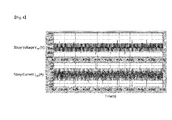
- FIG. 4 is a waveform view obtained through a simulation of a stray voltage and stray current in a conventional grid-connected parallel inverter.
- the conventional photovoltaic generation system using a double wiring transformer includes: a plurality of photovoltaic generation devices 110, 120, and 130; and a double wiring transformer 140 for transforming the output voltages of the photovoltaic generation devices 110, 120, and 130, wherein a grid 150 is connected with the output of the transformer 140.
- the photovoltaic generation devices 110, 120, and 130 include: photovoltaic modules 111, 121, and 131 for converting photovoltaic energy into DC electrical energy; inverters 112, 122, and 132 for converting the DC electrical energy into AC electrical energy; and LC filters 113, 123, and 133 for removing noise included in the AC electrical energy, respectively.
- an undesired stray capacitance Cst1 exists between the first photovoltaic module 111 and the ground G
- an undesired stray capacitance Cst2 exists between the second photovoltaic module 121 and the ground G. That is to say, a grounding impedance Zet1 and the undesired stray capacitance Cst1 exist between the first photovoltaic module 111 and the ground G, and a grounding impedance Zet2 and the undesired stray capacitance Cst2 exist between the second photovoltaic module 121 and the ground G, so that the first photovoltaic module 111 and second photovoltaic module 121 is at a connected state in a circuit.
- the plurality of photovoltaic generation devices operate in parallel, for example, a closed loop connected in order of "the first photovoltaic module 111, the first inverter 112, the first LC filter 113, the second LC filter 123, the second inverter 122, the second photovoltaic module 121, the second stray capacitor Cst2, and the first stray capacitor Cst1," and stray current flows along the closed loop.
- V cst - V sw ⁇ 12 - V sw ⁇ 22 - V sw ⁇ 32 - V sw ⁇ 11 - V sw ⁇ 21 - V sw ⁇ 31 3 - V pv
- the conventional photovoltaic generation system using a double wiring transformer causes undesired stray current, so that there is a danger of an electrical shock when the worker touches a photovoltaic module, the photovoltaic module is easily deteriorated and is easily broken due to the deterioration thereof, and high harmonic distortion appears in the output waveform of the inverter.
- the present invention has been made in an effort to address problems occurring in the related art.
- Embodiments provide a photovoltaic generation system using grid-connected parallel inverters which can significantly reduce stray current.
- Embodiments provide a photovoltaic generation system using grid-connected parallel inverters which can reduce deterioration of a photovoltaic module due to stray current.
- Embodiments provide a photovoltaic generation system using grid-connected parallel inverters which can reduce harmonic distortion in an output waveform.
- Embodiments provide a photovoltaic generation system using grid-connected parallel inverters which significantly reduces stray current using a Y-connected capacitor group and thus can use a double wiring transformer instead of a multi-wiring transformer.
- a photovoltaic generation system using grid-connected parallel inverters comprising: a plurality of photovoltaic generation devices connected in parallel with each other; and a transformer configured to transform and transfer output voltages of the photovoltaic generation devices to a grid
- the photovoltaic generation device comprises: a photovoltaic module configured to convert photovoltaic energy into DC electrical energy; an inverter configured to convert the DC electrical energy outputted from the photovoltaic module into AC electrical energy; an LC filter configured to remove noise included in the AC electrical energy which is outputted from the inverter; and a Y-connected capacitor group which is connected between one terminal of a reactor in the LC filter and one terminal of the photovoltaic module and is configured to reduce stray current.
- the LC filter further comprises a delta-connected capacitor group configured to filter noise at an output terminal of the inverter.
- a stray impedance value by a stray capacitance component between the photovoltaic module and a ground is larger than an impedance value by the Y-connected capacitor group.
- a frequency forming an impedance by the Y-connected capacitor group is a switching frequency of the inverter.
- stray current flowing between the photovoltaic module and a ground is dependent on a capacitance value of the Y-connected capacitor group and a switching frequency of the inverter.
- a resonance frequency by the LC filter and the Y-connected capacitor group is different from a switching frequency of the inverter.
- the transformer is any one of a double wiring transformer and a multi-wiring transformer.
- a photovoltaic generation system using grid-connected parallel inverters comprising: a photovoltaic module configured to convert photovoltaic energy into DC electrical energy; an inverter configured to convert the DC electrical energy outputted from the photovoltaic module into AC electrical energy; an LC filter configured to remove noise included in the AC electrical energy which is outputted from the inverter; a Y-connected capacitor group which is connected between one terminal of a reactor in the LC filter and one terminal of the photovoltaic module and is configured to reduce stray current; and an isolation transformer configured to block the output of a DC portion outputted from the LC filter.
- stray current flowing between the photovoltaic module and a ground is determined depending on a capacitance value of the Y-connected capacitor group and a switching frequency of the inverter.
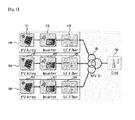
- a photovoltaic generation system using grid-connected parallel inverters includes a plurality of photovoltaic generation devices 410 and 420 connected in parallel with each other, a transformer 440 for transforming the output voltages of the photovoltaic generation devices 410 and 420, and a grid 450 connected with the output of the transformer 440.
- a double wiring transformer or any of multi-wiring transformers may be used as the transformer 440.
- the photovoltaic generation devices 410 and 420 include: photovoltaic modules 411 and 421 for converting photovoltaic energy into DC electrical energy; inverters 412 and 422 for converting the DC electrical energy outputted from the photovoltaic modules 411 and 421 into AC electrical energy; LC filters 413 and 423 for removing noise included in the AC electrical energy which are outputted from the inverters 412 and 422; and Y-connected capacitor groups 414 and 424 which are connected between one terminals of reactors in the LC filters 413 and 423 and one terminals of the photovoltaic modules 411 and 421 and reduce stray current, respectively.
- each of the LC filters 413 and 423 includes a delta-connected capacitor group.
- Vcst - V sw ⁇ 12 - Lf A ⁇ 2 ⁇ di dt - V cf ⁇ 2 ⁇ A
- V cst - V sw ⁇ 22 - Lf B ⁇ 2 ⁇ di dt - V cf ⁇ 2 ⁇ B
- V cst - V sw ⁇ 32 - Lf C ⁇ 2 ⁇ di dt - V cf ⁇ 2 ⁇ C
- Equation 8 is expressed as Equation 9.
- V cst - V sw ⁇ 12 - V sw ⁇ 22 - V sw ⁇ 32 - V sw ⁇ 11 - V sw ⁇ 21 - V sw ⁇ 31 3 - V pv
- the voltage component Vcst may be regarded as a sine-wave form of each phase in which a switching frequency is reduced. Therefore, since a three-phase voltage is zero in parallel, the voltage applied to the stray capacitor has a value near to zero.
- the resonance frequency fr is expressed as Equation 10, wherein a reactance is a reactor value of an LC filter, and a capacitance is a value of a Y-connected capacitor group.
- f represents the switching frequency of the inverter.
- the present disclosure provides a photovoltaic generation system which can significantly reduce stray current, reduce the deterioration of the photovoltaic module by stray current, and reduce harmonic distortion in an output waveform.
- a Y-connected capacitor group is adopted to significantly reduce stray current, it is possible to use a double wiring transformer in an advantageous position for price, volume, weight, design, etc., as compared with multi-wiring transformers.
Landscapes
- Engineering & Computer Science (AREA)
- Power Engineering (AREA)
- Inverter Devices (AREA)
Applications Claiming Priority (1)
| Application Number | Priority Date | Filing Date | Title |
|---|---|---|---|
| KR20110097363A KR101220230B1 (ko) | 2011-09-27 | 2011-09-27 | 계통 연계형 병렬 인버터를 이용한 태양광 발전 시스템 |
Publications (2)
| Publication Number | Publication Date |
|---|---|
| EP2575229A2 true EP2575229A2 (de) | 2013-04-03 |
| EP2575229A3 EP2575229A3 (de) | 2014-01-08 |
Family
ID=44862804
Family Applications (1)
| Application Number | Title | Priority Date | Filing Date |
|---|---|---|---|
| EP20110187245 Pending EP2575229A3 (de) | 2011-09-27 | 2011-10-31 | Photovoltaikgeneratorsystem mit angeschlossenem Netz paralleler Wechselrichter |
Country Status (3)
| Country | Link |
|---|---|
| US (1) | US20130076151A1 (de) |
| EP (1) | EP2575229A3 (de) |
| KR (1) | KR101220230B1 (de) |
Cited By (3)
| Publication number | Priority date | Publication date | Assignee | Title |
|---|---|---|---|---|
| CN104124876A (zh) * | 2013-04-29 | 2014-10-29 | 洛克威尔自动控制技术股份有限公司 | 用于有源前端滤波电容器劣化检测的方法和装置 |
| WO2019215372A1 (es) * | 2018-05-09 | 2019-11-14 | Power Electronics S.L. | Inversor solar fotovoltaico modular |
| WO2022170578A1 (zh) * | 2021-02-10 | 2022-08-18 | 华为数字能源技术有限公司 | 逆变装置及逆变系统 |
Families Citing this family (20)
| Publication number | Priority date | Publication date | Assignee | Title |
|---|---|---|---|---|
| US9653984B2 (en) | 2012-04-30 | 2017-05-16 | Rockwell Automation Technologies, Inc. | Filter capacitor degradation detection apparatus and method |
| KR101283554B1 (ko) | 2013-02-25 | 2013-07-15 | 데스틴파워 주식회사 | 제어 모드에 따라 자동으로 가변되는 필터 구조를 갖는 인버터 시스템 |
| US9898018B2 (en) * | 2013-03-14 | 2018-02-20 | Arda Power Inc. | Power clipping method and system |
| US10666047B2 (en) | 2013-03-14 | 2020-05-26 | Arda Power Inc. | Power management concept in DC distributed systems |
| US9294005B2 (en) * | 2013-10-01 | 2016-03-22 | Rockwell Automation Technologies, Inc. | Method and apparatus for detecting AFE filter capacitor degradation |
| KR101346579B1 (ko) * | 2013-10-08 | 2014-01-06 | 데스틴파워 주식회사 | 태양광 발전용 계통 연계형 병렬 인버터 시스템 |
| US9651592B2 (en) | 2013-12-03 | 2017-05-16 | Rockwell Automation Technologies, Inc. | Impedance detector apparatus and method |
| US9488686B2 (en) | 2014-02-24 | 2016-11-08 | Rockwell Automation Technologies, Inc. | Filter capacitor degradation identification using computed current |
| US9490690B2 (en) | 2014-03-11 | 2016-11-08 | Rockwell Automation Technologies, Inc. | Filter capacitor degradation identification using computed power |
| US9389263B2 (en) | 2014-06-05 | 2016-07-12 | Rockwell Automation Technologies, Inc. | Filter capacitor degradation identification using measured and expected voltage |
| FR3031849B1 (fr) * | 2015-01-16 | 2017-02-17 | Alstom Transp Tech | Convertisseur d'alimentation reseau et/ou de sous-station de recuperation de l'energie de freinage |
| US9735696B2 (en) | 2015-11-25 | 2017-08-15 | Rockwell Automation Technologies, Inc. | Filter capacitor degradation and calibration |
| CN106856332A (zh) * | 2017-03-20 | 2017-06-16 | 国家电网公司 | 一种分布式光伏发电并网系统 |
| CN107634539A (zh) * | 2017-10-17 | 2018-01-26 | 中国地质大学(武汉) | 一种并网逆变器 |
| CN108521144A (zh) * | 2018-04-24 | 2018-09-11 | 北京铂阳顶荣光伏科技有限公司 | 光伏发电系统及谐波抑制方法及设备 |
| CN110380450B (zh) * | 2019-08-13 | 2021-03-12 | 南方电网科学研究院有限责任公司 | 一种光伏控制方法、装置、设备及计算机可读存储介质 |
| CN110535369A (zh) * | 2019-09-30 | 2019-12-03 | 深圳古瑞瓦特新能源股份有限公司 | 一种高功率密度非隔离型光伏并网逆变器 |
| CN113437758B (zh) * | 2021-06-25 | 2022-07-26 | 安徽海螺建材设计研究院有限责任公司 | 水泥厂的光伏并网系统及计量方法 |
| CN217428000U (zh) * | 2022-03-25 | 2022-09-13 | 阳光电源股份有限公司 | 逆变器及逆变系统 |
| CN115642647A (zh) * | 2022-11-08 | 2023-01-24 | 河北科技大学 | 一种电流型逆变器输入串联输出并联的光伏发电系统 |
Family Cites Families (11)
| Publication number | Priority date | Publication date | Assignee | Title |
|---|---|---|---|---|
| US6586900B2 (en) * | 1999-02-08 | 2003-07-01 | Baker Hughes Incorporated | Method for boosting the output voltage of a variable frequency drive |
| US6404655B1 (en) * | 1999-12-07 | 2002-06-11 | Semikron, Inc. | Transformerless 3 phase power inverter |
| JP4052154B2 (ja) | 2003-03-14 | 2008-02-27 | 株式会社明電舎 | 分散型電源の出力安定化装置とその制御方法。 |
| US7177165B2 (en) * | 2004-06-21 | 2007-02-13 | Ballard Power Systems Corporation | System and method for unbalanced independent AC phase voltage control of a 3-phase, 4-wire output DC/AC inverter |
| US7239113B2 (en) * | 2005-05-03 | 2007-07-03 | Caterpillar Inc | Method for reducing undesired currents in an electrical power generation system |
| US7365511B2 (en) * | 2006-09-12 | 2008-04-29 | Hamilton Sundstrand Corporation | Methods to control high speed electric machines having a front-end EMI filter attached |
| US8068352B2 (en) * | 2008-12-19 | 2011-11-29 | Caterpillar Inc. | Power inverter control for grid-tie transition |
| EP2219276B1 (de) * | 2009-02-11 | 2015-12-02 | SMA Solar Technology AG | Photovoltaikanlage zur dreiphasigen Einspeisung in ein elektrisches Energieversorgungsnetz |
| US20100213768A1 (en) * | 2009-02-24 | 2010-08-26 | Alex Faveluke | Apparatus for photovoltaic power generation |
| KR100911122B1 (ko) | 2009-05-21 | 2009-08-11 | (주)그린파워테크놀로지스 | 복수의 dc 전원을 교류로 변환하는 개선된 전력변환장치 |
| KR20100133792A (ko) * | 2009-06-12 | 2010-12-22 | (주) 다쓰테크 | 태양광 계통 연계형 삼상 인버터 회로 |
-
2011
- 2011-09-27 KR KR20110097363A patent/KR101220230B1/ko active Active
- 2011-10-21 US US13/278,962 patent/US20130076151A1/en not_active Abandoned
- 2011-10-31 EP EP20110187245 patent/EP2575229A3/de active Pending
Non-Patent Citations (1)
| Title |
|---|
| None |
Cited By (5)
| Publication number | Priority date | Publication date | Assignee | Title |
|---|---|---|---|---|
| CN104124876A (zh) * | 2013-04-29 | 2014-10-29 | 洛克威尔自动控制技术股份有限公司 | 用于有源前端滤波电容器劣化检测的方法和装置 |
| CN104124876B (zh) * | 2013-04-29 | 2017-05-10 | 洛克威尔自动控制技术股份有限公司 | 用于有源前端滤波电容器劣化检测的方法和装置 |
| WO2019215372A1 (es) * | 2018-05-09 | 2019-11-14 | Power Electronics S.L. | Inversor solar fotovoltaico modular |
| US11552577B2 (en) | 2018-05-09 | 2023-01-10 | Power Electronics España, S.L. | Modular photovoltaic solar inverter |
| WO2022170578A1 (zh) * | 2021-02-10 | 2022-08-18 | 华为数字能源技术有限公司 | 逆变装置及逆变系统 |
Also Published As
| Publication number | Publication date |
|---|---|
| EP2575229A3 (de) | 2014-01-08 |
| KR101220230B1 (ko) | 2013-01-09 |
| US20130076151A1 (en) | 2013-03-28 |
Similar Documents
| Publication | Publication Date | Title |
|---|---|---|
| US20130076151A1 (en) | Photovoltaic generation system using parallel inverter connected grid | |
| Ruddy et al. | Low Frequency AC transmission for offshore wind power: A review | |
| Reed et al. | Ship to grid: Medium-voltage DC concepts in theory and practice | |
| Xiao et al. | Review of grid‐tied converter topologies used in photovoltaic systems | |
| Moḥ. Rabiula Isalāma et al. | Power converters for medium voltage networks | |
| Pharne et al. | A review on multilevel inverter topology | |
| Gnanarathna et al. | Modular multi-level converter based HVDC system for grid connection of offshore wind power plant | |
| Islam et al. | A 43-level 33 kV 3-phase modular multilevel cascaded converter for direct grid integration of renewable generation systems | |
| Quan et al. | Reconsideration of grid-friendly low-order filter enabled by parallel converters | |
| Islam et al. | Performance and cost comparison of NPC, FC and SCHB multilevel converter topologies for high-voltage applications | |
| Hamdan et al. | Hosting capacity enhancement for photovoltaic systems at various conditions based on Volt-Var control | |
| KR101346579B1 (ko) | 태양광 발전용 계통 연계형 병렬 인버터 시스템 | |
| Id Bouhouch et al. | Comparative analysis of three-phase photovoltaic inverters control techniques | |
| Ahrabian et al. | Hybrid filter applications for power quality improvement of power distribution networks utilizing renewable energies | |
| Kumar et al. | PV-based shunt active power filter for improving power quality in accordance with the PQ theory | |
| Dybko et al. | Switching frequency circulating current analysis in parallel-connected multilevel NPC converters | |
| Esmaeili et al. | The effect of various types of distributed generations on ferroresonance | |
| Klumpner et al. | Experimental evaluation of an energy storage system for medium voltage distribution grids enabling solid‐state substation functionality | |
| Ajayi-Obe | Development of a multilevel converter topology for transformer-less connection of renewable energy systems | |
| Garipelly | Improvement of power quality of a distributed generation power system | |
| Pawar et al. | A Review on Harmonic Reduction Techniques in Three-Phase Power Generation in PV Solar Plants | |
| Almeida et al. | Analysis of a MMC-Based 12-MW Direct-Drive Wind Energy Conversion System With Level-Shifted and PS-PWM and NLM Strategies | |
| Wargiya | A study on the propagation of harmonics in a Power System | |
| Nathan | A Novel DC-DC Converter for Photovoltaic Applications | |
| Rao et al. | A Hybrid PV-Wind single-phase transformer-less grid-connected cascaded NPC inverter minimizing leakage currents |
Legal Events
| Date | Code | Title | Description |
|---|---|---|---|
| PUAI | Public reference made under article 153(3) epc to a published international application that has entered the european phase |
Free format text: ORIGINAL CODE: 0009012 |
|
| AK | Designated contracting states |
Kind code of ref document: A2 Designated state(s): AL AT BE BG CH CY CZ DE DK EE ES FI FR GB GR HR HU IE IS IT LI LT LU LV MC MK MT NL NO PL PT RO RS SE SI SK SM TR |
|
| AX | Request for extension of the european patent |
Extension state: BA ME |
|
| PUAL | Search report despatched |
Free format text: ORIGINAL CODE: 0009013 |
|
| AK | Designated contracting states |
Kind code of ref document: A3 Designated state(s): AL AT BE BG CH CY CZ DE DK EE ES FI FR GB GR HR HU IE IS IT LI LT LU LV MC MK MT NL NO PL PT RO RS SE SI SK SM TR |
|
| AX | Request for extension of the european patent |
Extension state: BA ME |
|
| RIC1 | Information provided on ipc code assigned before grant |
Ipc: H02J 13/00 20060101ALI20131203BHEP Ipc: H02M 7/42 20060101ALI20131203BHEP Ipc: H02J 3/38 20060101ALI20131203BHEP Ipc: F24J 2/52 20060101ALI20131203BHEP Ipc: H01L 31/0224 20060101ALI20131203BHEP Ipc: H02J 3/00 20060101AFI20131203BHEP |
|
| 17P | Request for examination filed |
Effective date: 20140708 |
|
| RBV | Designated contracting states (corrected) |
Designated state(s): AL AT BE BG CH CY CZ DE DK EE ES FI FR GB GR HR HU IE IS IT LI LT LU LV MC MK MT NL NO PL PT RO RS SE SI SK SM TR |
|
| 17Q | First examination report despatched |
Effective date: 20140801 |
|
| 18D | Application deemed to be withdrawn |
Effective date: 20150211 |
|
| D18D | Application deemed to be withdrawn (deleted) | ||
| STAA | Information on the status of an ep patent application or granted ep patent |
Free format text: STATUS: THE APPLICATION IS DEEMED TO BE WITHDRAWN |
|
| R18D | Application deemed to be withdrawn (corrected) |
Effective date: 20150212 |