EP2575157A2 - Dual-energy X-ray tubes - Google Patents
Dual-energy X-ray tubes Download PDFInfo
- Publication number
- EP2575157A2 EP2575157A2 EP12186491A EP12186491A EP2575157A2 EP 2575157 A2 EP2575157 A2 EP 2575157A2 EP 12186491 A EP12186491 A EP 12186491A EP 12186491 A EP12186491 A EP 12186491A EP 2575157 A2 EP2575157 A2 EP 2575157A2
- Authority
- EP
- European Patent Office
- Prior art keywords
- cathode
- energy
- dual
- ray tube
- anode
- Prior art date
- Legal status (The legal status is an assumption and is not a legal conclusion. Google has not performed a legal analysis and makes no representation as to the accuracy of the status listed.)
- Withdrawn
Links
- 230000009977 dual effect Effects 0.000 claims description 9
- 239000000463 material Substances 0.000 description 8
- 230000001351 cycling effect Effects 0.000 description 2
- 239000010963 304 stainless steel Substances 0.000 description 1
- 229910000589 SAE 304 stainless steel Inorganic materials 0.000 description 1
- 238000010521 absorption reaction Methods 0.000 description 1
- 229910052790 beryllium Inorganic materials 0.000 description 1
- ATBAMAFKBVZNFJ-UHFFFAOYSA-N beryllium atom Chemical compound [Be] ATBAMAFKBVZNFJ-UHFFFAOYSA-N 0.000 description 1
- 238000009413 insulation Methods 0.000 description 1
- 238000002955 isolation Methods 0.000 description 1
- 238000004519 manufacturing process Methods 0.000 description 1
- 229910001220 stainless steel Inorganic materials 0.000 description 1
- 239000010935 stainless steel Substances 0.000 description 1
- WFKWXMTUELFFGS-UHFFFAOYSA-N tungsten Chemical compound [W] WFKWXMTUELFFGS-UHFFFAOYSA-N 0.000 description 1
- 229910052721 tungsten Inorganic materials 0.000 description 1
- 239000010937 tungsten Substances 0.000 description 1
Images



Classifications
-
- H—ELECTRICITY
- H01—ELECTRIC ELEMENTS
- H01J—ELECTRIC DISCHARGE TUBES OR DISCHARGE LAMPS
- H01J35/00—X-ray tubes
- H01J35/02—Details
- H01J35/04—Electrodes ; Mutual position thereof; Constructional adaptations therefor
- H01J35/08—Anodes; Anti cathodes
- H01J35/112—Non-rotating anodes
-
- H—ELECTRICITY
- H01—ELECTRIC ELEMENTS
- H01J—ELECTRIC DISCHARGE TUBES OR DISCHARGE LAMPS
- H01J35/00—X-ray tubes
- H01J35/02—Details
- H01J35/04—Electrodes ; Mutual position thereof; Constructional adaptations therefor
- H01J35/06—Cathodes
-
- H—ELECTRICITY
- H01—ELECTRIC ELEMENTS
- H01J—ELECTRIC DISCHARGE TUBES OR DISCHARGE LAMPS
- H01J2235/00—X-ray tubes
- H01J2235/06—Cathode assembly
- H01J2235/068—Multi-cathode assembly
Definitions
- An x-ray tube typically includes a cathode and an anode positioned within an evacuated enclosure.
- the cathode includes an electron emitter and the anode includes a target surface that is oriented to receive electrons emitted by the electron emitter.
- an electric current is applied to the electron emitter, which causes electrons to be produced by thermionic emission.
- the electrons are then accelerated toward the target surface of the anode by applying a high-voltage potential between the cathode assembly and the anode.
- the kinetic energy of the electrons causes the production of x-rays.
- the x-rays are produced in an omnidirectional fashion where the useful portion ultimately exits the x-ray tube through a window in the x-ray tube, and interacts with a material sample, patient, or other object with the remainder being absorbed by other structures including those whose specific purpose is absorption of x-rays with non-useful trajectories or energies.
- x-ray energy a distribution of energies with a mean value
- x-ray energy a mean value
- example embodiments relate to dual-energy x-ray tubes.
- the example dual-energy x-ray tubes disclosed herein include two cathodes configured to emit electrons at different energies resulting in the generation of x-rays at different energies.
- the generation of x-rays having different energies from a single x-ray tube can be useful in applications where attempts are made to detect materials of different densities.
- a dual-energy x-ray tube includes an evacuated enclosure, an anode positioned within the evacuated enclosure, a first cathode positioned within the evacuated enclosure, and a second cathode positioned within the evacuated enclosure.
- the first cathode and the second cathode are configured to operate simultaneously at different voltages.
- a dual-energy x-ray tube in another example embodiment, includes an evacuated enclosure, an anode positioned within the evacuated enclosure, a first cathode positioned within the evacuated enclosure, and a second cathode positioned within the evacuated enclosure.
- the anode is configured to operate at a positive high voltage.
- the first cathode is configured to operate at a negative high voltage.
- the second cathode is configured to operate at about zero voltage.
- the first cathode and the second cathode are configured to continuously operate simultaneously.
- a dual-energy x-ray system includes a high-voltage generator configured to continuously generate a single positive high voltage and a single negative high voltage and an x-ray tube.
- the x-ray tube includes an evacuated enclosure, an anode positioned within the evacuated enclosure, a first cathode positioned within the evacuated enclosure, and a second cathode positioned within the evacuated enclosure.
- the anode is configured to operate at the single positive high voltage.
- the first cathode is configured to operate at the single negative high voltage.
- the second cathode is configured to operate at about zero voltage.
- the first cathode and the second cathode are configured to continuously operate simultaneously.
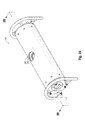
- Figure 1A is a perspective view of an example x-ray tube
- Figure 1B is a cross-sectional side view of the example x-ray tube of Figure 1A ;
- Figure 2A is a perspective view of a second example x-ray tube.
- Figure 2B is a cross-sectional side view of the second example x-ray tube of Figure 2A .
- Example embodiments of the present invention relate to dual-energy x-ray tubes.
- a first example dual-energy x-ray tube 100 is disclosed.
- the example x-ray tube 100 generally includes a can 102 and an x-ray tube window 104 attached to the can 102.
- the x-ray tube window 104 is comprised of an x-ray transmissive material, such as beryllium or other suitable material(s).
- the can 102 may be formed from stainless steel, such as 304 stainless steel.
- the x-ray tube window 104 and the can 102 at least partially define an evacuated enclosure 106 within which an anode 108, a first cathode 110, and a second cathode 112 are positioned. More particularly, the first and second cathodes 110 and 112 extend into the can 102 and the anode 108 is also positioned within the can 102. The anode 108 is spaced apart from and oppositely disposed to the cathodes 110 and 112.
- the anode 108 and the first cathode 110 are connected in a first electrical circuit that allows for the application of a first high voltage potential between the anode 108 and the first cathode 110.
- the anode 108 and the second cathode 112 are connected in a second electrical circuit that allows for the application of a second high voltage potential between the anode 108 and the second cathode 112.
- the anode 108 is configured to operate at a positive high voltage
- the first cathode 110 is configured to operate at a negative high voltage
- the second cathode 112 is configured to operate at about zero voltage.
- the anode 108 and the first cathode 110 are both electrically insulated from about ground, while the second cathode 112 is not electrically insulated from about ground and thus requires no high-voltage stand-off.
- the evacuated enclosure 106 is evacuated to create a vacuum. Then, during operation of the example x-ray tube 100, a positive high voltage is electrically applied to the anode 108 while a negative high voltage is electrically applied to the emitters 114 of the first cathode 110 and an about ground voltage is electrically applied to the emitters 116 of the second cathode 112 to cause electrons to be emitted from the cathodes 110 and 112 by thermionic emission.
- the application of high voltage differentials between the anode 108 and the cathodes 110 and 112 then causes the electrons to accelerate from the cathodes 110 and 112 toward a focal spot of a target 118 that is positioned on the anode 108.
- the target 118 may be composed for example of tungsten or other material(s) having a high atomic ("high Z") number. As the electrons accelerate, they gain a substantial amount of kinetic energy, and upon striking the focal spot on the target 118, some of this kinetic energy is converted into x-rays.
- the target 118 is oriented so that many of the emitted x-rays are visible to the x-ray tube window 104.
- the x-ray tube window 104 is comprised of an x-ray transmissive material, the x-rays emitted from the focal spot on the target 118 pass through the x-ray tube window 104 in order to image an intended target (not shown) to produce an x-ray image (not shown).
- the window 104 therefore hermetically seals the vacuum of the evacuated enclosure of the x-ray tube 100 from the atmospheric air pressure outside the x-ray tube 100 and yet enables the x-rays generated by the anode 108 to exit the x-ray tube 100.
- the cathodes 110 and 112 include emitters 114 and 116, respectively.
- the emitter 114 of the cathode 110 and the anode 108 are both configured to be electrically connected to an appropriate high-voltage generator (not shown).
- a bi-polar high-voltage generator (not shown) may be configured to continuously generate a single positive high voltage and a single negative high voltage.
- the single positive high voltage can define the voltage potential of the anode 108 and the single negative high voltage can define the voltage potential of the cathode 110.
- An about ground voltage can define the voltage potential of the cathode 112.
- the high-voltage generator (not shown) can be configured to produce a voltage potential on the anode 108 at a voltage between about 50kV and about 320kV and the first cathode 110 at a voltage between about -320kV and about -50kV.
- the high-voltage generator (not shown) may be balanced such that the single positive high voltage is about opposite the single negative high voltage.
- the anode 108 may be configured to operate at about 75kV
- the first cathode 110 may be configured to operate at about -75kV
- the second cathode 112 may be configured to operate at 0kV.
- This example results in the generation of x-rays at about 150keV from the first cathode 110 and x-rays at about 75keV from the second cathode 112.
- the operation of the second cathode 112 results in x-rays that are about half the energy of the x-rays that result from the operation of the first cathode 110.
- the high-voltage generator (not shown) may be unbalanced such that the single positive high voltage is not opposite the single negative high voltage.
- the anode 108 may be configured to operate at about 50kV
- the first cathode 110 may be configured to operate at about -100kV
- the second cathode 112 may be configured to operate at 0kV.
- This example results in the generation of x-rays at about 150keV from the first cathode 110 and x-rays at about 50keV from the second cathode 112.
- the operation of the second cathode 112 results in x-rays that are less than half the energy of the x-rays that result from the operation of the first cathode 110.
- an unbalanced high-voltage generator (not shown) could alternatively be configured such that the operation of the second cathode 112 result in x-rays that are greater than half the energy of the x-rays that result from the operation of the first cathode 110. It is also noted that in this example the total voltage potential difference between the cathode 110 and the anode 108 is equal to the previous example at 150keV, while the voltage potential difference between cathode 112 and the anode 108 is reduced to 50keV.
- the x-ray tube 100 is configured to generate x-rays at dual energies simultaneously or intermittently, with the energy of the x-rays produced by the cathode 110 being higher than the energy of the x-rays produced by the cathode 112.
- the x-ray tube 100 can therefore be employed in connection with an x-ray detector, such as a flat-panel detector, that is specifically designed to simultaneously detect x-rays at each of the dual energies.
- the example x-ray tube 200 includes a can 202 and an x-ray tube window 204, which at least partially define an evacuated enclosure 206 within which an anode 208, a first cathode 210, and a second cathode 212 are positioned.
- the anode 208 and the first cathode 210 are connected in a first electrical circuit that allows for the application of a first high voltage potential between the anode 208 and the first cathode 210 and the anode 208 and the second cathode 212 are connected in a second electrical circuit that allows for the application of a second high voltage potential between the anode 208 and the second cathode 212.
- the anode 208 is configured to operate at a positive high voltage
- the first cathode 210 is configured to operate at a negative high voltage
- the second cathode 212 is configured to operate at about zero voltage.
- the second example x-ray tube 200 further includes grids 220 and 222 positioned within the evacuated enclosure 206 between the first and second emitters 214 and 216, respectively, and the anode 208.
- the operation of the second example x-ray tube 200 of Figures 2A and 2B is similar to the operation of the first example x-ray tube of Figures 1A and 1B , except that during operation of the second example x-ray tube 200 the grids 220 and 222 are configured to substantially allow electrons to reach the anode 208 from only the first emitter 214 or the second emitter 216 at any given time.
- the x-ray tube 200 may rapidly cycle between operation of the grid 220, which prevents the emission of electrons from the first emitter 214, and operation of the grid 222, which prevents the emission of electrons from the second emitter 216.
- the x-ray tube 200 is therefore configured to consecutively generate x-rays at dual energies, with the energy of the x-rays produced by the cathode 210 being higher than the energy of the x-rays produced by the cathode 212.
- the x-ray tube 200 can be employed in connection with an x-ray detector, such as a flat-panel detector, that is specifically designed to consecutively detect x-rays at each of the dual energies.
- example x-ray tubes 100 and 200 are depicted as stationary anode x-ray tubes, the example dual-energy x-ray configurations disclosed herein may alternatively be employed, for example, in rotatable anode x-ray tubes. Also, while the example x-ray tubes 100 and 200 are configured for use in baggage scanning applications, but it is understood that the dual-energy x-ray configurations disclosed herein can be employed in x-ray tubes configured for use in other applications including, but not limited to, other industrial or medical applications.
- example x-ray tube 100 is disclosed in connection with Figure 1B as not including any grid, it is understood that the example grids 220 and 222 disclosed in Figure 2B could be employed in the example x-ray tube 100 to enable the consecutive generation of x-rays at dual energies, or to alternate between consecutive generation and simultaneous generation of x-rays at dual energies. It is further understood that a single grid with multiple operational portions could be employed in place of the grids 220 and 222, where the operational portions can be cyclically activated and deactivated.
Landscapes
- Apparatus For Radiation Diagnosis (AREA)
- X-Ray Techniques (AREA)
Abstract
Description
- X-ray tubes are extremely valuable tools that are used in a wide variety of applications, both industrial and medical. An x-ray tube typically includes a cathode and an anode positioned within an evacuated enclosure. The cathode includes an electron emitter and the anode includes a target surface that is oriented to receive electrons emitted by the electron emitter. During operation of the x-ray tube, an electric current is applied to the electron emitter, which causes electrons to be produced by thermionic emission. The electrons are then accelerated toward the target surface of the anode by applying a high-voltage potential between the cathode assembly and the anode. When the electrons strike the anode target surface, the kinetic energy of the electrons causes the production of x-rays. The x-rays are produced in an omnidirectional fashion where the useful portion ultimately exits the x-ray tube through a window in the x-ray tube, and interacts with a material sample, patient, or other object with the remainder being absorbed by other structures including those whose specific purpose is absorption of x-rays with non-useful trajectories or energies.
- During the operation of a typical x-ray tube, electrons are produced at a single energy resulting in x-rays having a distribution of energies with a mean value, herein referred to as x-ray energy. While having one x-ray energy is useful, in some situations it would be desirable to examine a material sample, patient, or other object with x-rays having different x-ray energies. For example, x-rays having multiple energies would be useful in baggage scanning applications where attempts are made to detect materials of different densities.
- The subject matter claimed herein is not limited to embodiments that solve any disadvantages or that operate only in environments such as those described above. Rather, this background is only provided to illustrate one exemplary technology area where some embodiments described herein may be practiced.
- In general, example embodiments relate to dual-energy x-ray tubes. The example dual-energy x-ray tubes disclosed herein include two cathodes configured to emit electrons at different energies resulting in the generation of x-rays at different energies. Among other things, the generation of x-rays having different energies from a single x-ray tube can be useful in applications where attempts are made to detect materials of different densities.
- In one example embodiment, a dual-energy x-ray tube includes an evacuated enclosure, an anode positioned within the evacuated enclosure, a first cathode positioned within the evacuated enclosure, and a second cathode positioned within the evacuated enclosure. The first cathode and the second cathode are configured to operate simultaneously at different voltages.
- In another example embodiment, a dual-energy x-ray tube includes an evacuated enclosure, an anode positioned within the evacuated enclosure, a first cathode positioned within the evacuated enclosure, and a second cathode positioned within the evacuated enclosure. The anode is configured to operate at a positive high voltage. The first cathode is configured to operate at a negative high voltage. The second cathode is configured to operate at about zero voltage. The first cathode and the second cathode are configured to continuously operate simultaneously.
- In yet another example embodiment, a dual-energy x-ray system includes a high-voltage generator configured to continuously generate a single positive high voltage and a single negative high voltage and an x-ray tube. The x-ray tube includes an evacuated enclosure, an anode positioned within the evacuated enclosure, a first cathode positioned within the evacuated enclosure, and a second cathode positioned within the evacuated enclosure. The anode is configured to operate at the single positive high voltage. The first cathode is configured to operate at the single negative high voltage. The second cathode is configured to operate at about zero voltage. The first cathode and the second cathode are configured to continuously operate simultaneously.
- These and other aspects of example embodiments of the invention will become more fully apparent from the following description and appended claims.
- To further clarify certain aspects of the present invention, a more particular description of the invention will be rendered by reference to example embodiments thereof which are disclosed in the appended drawings. It is appreciated that these drawings depict only example embodiments of the invention and are therefore not to be considered limiting of its scope. Aspects of example embodiments of the invention will be described and explained with additional specificity and detail through the use of the accompanying drawings in which:
-
Figure 1A is a perspective view of an example x-ray tube; -
Figure 1B is a cross-sectional side view of the example x-ray tube ofFigure 1A ; -
Figure 2A is a perspective view of a second example x-ray tube; and -
Figure 2B is a cross-sectional side view of the second example x-ray tube ofFigure 2A . - Example embodiments of the present invention relate to dual-energy x-ray tubes. Reference will now be made to the drawings to describe various aspects of example embodiments of the invention. It is to be understood that the drawings are diagrammatic and schematic representations of such example embodiments, and are not limiting of the present invention, nor are they necessarily drawn to scale.
- With reference first to
Figures 1A and1B , a first example dual-energy x-ray tube 100 is disclosed. As disclosed inFigure 1A , theexample x-ray tube 100 generally includes acan 102 and anx-ray tube window 104 attached to thecan 102. Thex-ray tube window 104 is comprised of an x-ray transmissive material, such as beryllium or other suitable material(s). Thecan 102 may be formed from stainless steel, such as 304 stainless steel. - As disclosed in
Figure 1B , thex-ray tube window 104 and thecan 102 at least partially define an evacuated enclosure 106 within which an anode 108, afirst cathode 110, and asecond cathode 112 are positioned. More particularly, the first andsecond cathodes can 102 and the anode 108 is also positioned within thecan 102. The anode 108 is spaced apart from and oppositely disposed to thecathodes - The anode 108 and the
first cathode 110 are connected in a first electrical circuit that allows for the application of a first high voltage potential between the anode 108 and thefirst cathode 110. Similarly, the anode 108 and thesecond cathode 112 are connected in a second electrical circuit that allows for the application of a second high voltage potential between the anode 108 and thesecond cathode 112. In order to create x-rays at dual energies, the anode 108 is configured to operate at a positive high voltage, thefirst cathode 110 is configured to operate at a negative high voltage, and thesecond cathode 112 is configured to operate at about zero voltage. Thus, the anode 108 and thefirst cathode 110 are both electrically insulated from about ground, while thesecond cathode 112 is not electrically insulated from about ground and thus requires no high-voltage stand-off. - With continued reference to
Figure 1B , prior to operation of theexample x-ray tube 100, the evacuated enclosure 106 is evacuated to create a vacuum. Then, during operation of theexample x-ray tube 100, a positive high voltage is electrically applied to the anode 108 while a negative high voltage is electrically applied to the emitters 114 of thefirst cathode 110 and an about ground voltage is electrically applied to theemitters 116 of thesecond cathode 112 to cause electrons to be emitted from thecathodes cathodes cathodes target 118 that is positioned on the anode 108. Thetarget 118 may be composed for example of tungsten or other material(s) having a high atomic ("high Z") number. As the electrons accelerate, they gain a substantial amount of kinetic energy, and upon striking the focal spot on thetarget 118, some of this kinetic energy is converted into x-rays. - The
target 118 is oriented so that many of the emitted x-rays are visible to thex-ray tube window 104. As thex-ray tube window 104 is comprised of an x-ray transmissive material, the x-rays emitted from the focal spot on thetarget 118 pass through thex-ray tube window 104 in order to image an intended target (not shown) to produce an x-ray image (not shown). Thewindow 104 therefore hermetically seals the vacuum of the evacuated enclosure of thex-ray tube 100 from the atmospheric air pressure outside thex-ray tube 100 and yet enables the x-rays generated by the anode 108 to exit thex-ray tube 100. - As noted above, the
cathodes emitters 114 and 116, respectively. The emitter 114 of thecathode 110 and the anode 108 are both configured to be electrically connected to an appropriate high-voltage generator (not shown). For example, a bi-polar high-voltage generator (not shown) may be configured to continuously generate a single positive high voltage and a single negative high voltage. The single positive high voltage can define the voltage potential of the anode 108 and the single negative high voltage can define the voltage potential of thecathode 110. An about ground voltage can define the voltage potential of thecathode 112. For example, the high-voltage generator (not shown) can be configured to produce a voltage potential on the anode 108 at a voltage between about 50kV and about 320kV and thefirst cathode 110 at a voltage between about -320kV and about -50kV. - In some example embodiments, the high-voltage generator (not shown) may be balanced such that the single positive high voltage is about opposite the single negative high voltage. For example, the anode 108 may be configured to operate at about 75kV, the
first cathode 110 may be configured to operate at about -75kV, and thesecond cathode 112 may be configured to operate at 0kV. This example results in the generation of x-rays at about 150keV from thefirst cathode 110 and x-rays at about 75keV from thesecond cathode 112. Thus, the operation of thesecond cathode 112 results in x-rays that are about half the energy of the x-rays that result from the operation of thefirst cathode 110. - In other example embodiments, the high-voltage generator (not shown) may be unbalanced such that the single positive high voltage is not opposite the single negative high voltage. For example, the anode 108 may be configured to operate at about 50kV, the
first cathode 110 may be configured to operate at about -100kV, and thesecond cathode 112 may be configured to operate at 0kV. This example results in the generation of x-rays at about 150keV from thefirst cathode 110 and x-rays at about 50keV from thesecond cathode 112. Thus, the operation of thesecond cathode 112 results in x-rays that are less than half the energy of the x-rays that result from the operation of thefirst cathode 110. It is understood that an unbalanced high-voltage generator (not shown) could alternatively be configured such that the operation of thesecond cathode 112 result in x-rays that are greater than half the energy of the x-rays that result from the operation of thefirst cathode 110. It is also noted that in this example the total voltage potential difference between thecathode 110 and the anode 108 is equal to the previous example at 150keV, while the voltage potential difference betweencathode 112 and the anode 108 is reduced to 50keV. - Since both the
cathodes x-ray tube 100 is configured to generate x-rays at dual energies simultaneously or intermittently, with the energy of the x-rays produced by thecathode 110 being higher than the energy of the x-rays produced by thecathode 112. Thex-ray tube 100 can therefore be employed in connection with an x-ray detector, such as a flat-panel detector, that is specifically designed to simultaneously detect x-rays at each of the dual energies. - With reference now to
Figures 2A and2B , a second example dual-energy x-ray tube 200 is disclosed. As disclosed inFigures 2A and2B , theexample x-ray tube 200 includes acan 202 and anx-ray tube window 204, which at least partially define an evacuated enclosure 206 within which ananode 208, afirst cathode 210, and asecond cathode 212 are positioned. Similar to the configuration of thex-ray tube 100, theanode 208 and thefirst cathode 210 are connected in a first electrical circuit that allows for the application of a first high voltage potential between theanode 208 and thefirst cathode 210 and theanode 208 and thesecond cathode 212 are connected in a second electrical circuit that allows for the application of a second high voltage potential between theanode 208 and thesecond cathode 212. In order to create x-rays at dual energies, theanode 208 is configured to operate at a positive high voltage, thefirst cathode 210 is configured to operate at a negative high voltage, and thesecond cathode 212 is configured to operate at about zero voltage. Thus, theanode 208 and thefirst cathode 210 are both electrically insulated from about ground, while thesecond cathode 212 is not electrically insulated from about ground and thus requires no high-voltage stand-off. The secondexample x-ray tube 200 further includesgrids second emitters anode 208. - The operation of the second
example x-ray tube 200 ofFigures 2A and2B is similar to the operation of the first example x-ray tube ofFigures 1A and1B , except that during operation of the secondexample x-ray tube 200 thegrids anode 208 from only thefirst emitter 214 or thesecond emitter 216 at any given time. For example, thex-ray tube 200 may rapidly cycle between operation of thegrid 220, which prevents the emission of electrons from thefirst emitter 214, and operation of thegrid 222, which prevents the emission of electrons from thesecond emitter 216. In this manner, while both theemitters 215 and 216 are continuously operating, only electrons from one of theemitters anode 208 and producing x-rays at any given time. It is noted that cycling between the operation of thegrids second cathode 212 is not electrically insulated from about ground and thus requires no high-voltage stand-off, thegrid 222 may require some low voltage insulation isolation from ground. - The
x-ray tube 200 is therefore configured to consecutively generate x-rays at dual energies, with the energy of the x-rays produced by thecathode 210 being higher than the energy of the x-rays produced by thecathode 212. Thex-ray tube 200 can be employed in connection with an x-ray detector, such as a flat-panel detector, that is specifically designed to consecutively detect x-rays at each of the dual energies. - Although the
example x-ray tubes example x-ray tubes - Further, while the
example x-ray tube 100 is disclosed in connection withFigure 1B as not including any grid, it is understood that theexample grids Figure 2B could be employed in theexample x-ray tube 100 to enable the consecutive generation of x-rays at dual energies, or to alternate between consecutive generation and simultaneous generation of x-rays at dual energies. It is further understood that a single grid with multiple operational portions could be employed in place of thegrids - The example embodiments disclosed herein may be embodied in other specific forms. The example embodiments disclosed herein are therefore to be considered in all respects only as illustrative and not restrictive.
Claims (12)
- A dual-energy x-ray tube comprising:an evacuated enclosure (106);an anode (108) positioned within the evacuated enclosure (106);a first cathode (110) positioned within the evacuated enclosure (106);
anda second cathode (112) positioned within the evacuated enclosure (106),wherein the first cathode (110) and the second cathode (112) are configured to operate simultaneously at different voltages. - The dual-energy x-ray tube as recited in claim 1, wherein:the anode configured to operate at a positive high voltage;the first cathode configured to operate at a negative high voltage; andthe second cathode configured to operate at about zero voltage.
- The dual-energy x-ray tube as recited in claim 1 or 2, wherein:the anode is configured to operate between about 50kV and about 320kV; andthe first cathode is configured to operate at about -320kV and about -50kV.
- The dual-energy x-ray tube as recited in claim 1, 2 or 3, wherein the operation of the second cathode results in x-rays that are about half the energy of the x-rays that result from the operation of the first cathode.
- The dual-energy x-ray tube as recited in claim 1, 2 or 3, wherein the operation of the second cathode results in x-rays that have an energy level that is greater than or less than half the energy of the x-rays that result from the operation of the first cathode.
- The dual-energy x-ray tube as recited in any one of claims 1 to 5, wherein:the first cathode is electrically insulated from about ground; andthe second cathode is not electrically insulated from about ground.
- The dual-energy x-ray tube as recited in any one of claims 1 to 6, further comprising one or more grids positioned within the evacuated enclosure between the first and second cathodes and the anode, wherein the one or more grids are configured to substantially allow electrons to reach the anode from only an emitter of the first cathode or an emitter of the second cathode at any given time.
- The dual-energy x-ray tube as recited in any one of claims 1 to 7, wherein the x-ray tube is configured to generate x-rays at dual energies simultaneously.
- A dual-energy x-ray system comprising:a high-voltage generator configured to continuously generate a single positive high voltage and a single negative high voltage; andthe x-ray tube of any one of claims 1 to 8,wherein:the anode is configured to operate at the single positive high voltage;the first cathode is configured to operate at the single negative high voltage; andthe second cathode is configured to operate at about zero voltage.
- The dual-energy x-ray system as recited in claim 9, wherein the high-voltage generator is configured to continuously generate a single positive high voltage between about 50kV and about 320kV and a single negative high voltage between about -320kV and about -50kV.
- The dual-energy x-ray system as recited in claim 9 or 10, wherein the high-voltage generator is balanced such that the single positive high voltage is about opposite the single negative high voltage.
- The dual-energy x-ray system as recited in claim 9, 10 or 11, wherein the high-voltage generator is unbalanced such that the single positive high voltage is not opposite the single negative high voltage.
Applications Claiming Priority (1)
| Application Number | Priority Date | Filing Date | Title |
|---|---|---|---|
| US13/251,027 US9324536B2 (en) | 2011-09-30 | 2011-09-30 | Dual-energy X-ray tubes |
Publications (3)
| Publication Number | Publication Date |
|---|---|
| EP2575157A2 true EP2575157A2 (en) | 2013-04-03 |
| EP2575157A8 EP2575157A8 (en) | 2014-01-08 |
| EP2575157A3 EP2575157A3 (en) | 2014-01-22 |
Family
ID=47044839
Family Applications (1)
| Application Number | Title | Priority Date | Filing Date |
|---|---|---|---|
| EP12186491.2A Withdrawn EP2575157A3 (en) | 2011-09-30 | 2012-09-28 | Dual-energy X-ray tubes |
Country Status (2)
| Country | Link |
|---|---|
| US (1) | US9324536B2 (en) |
| EP (1) | EP2575157A3 (en) |
Cited By (1)
| Publication number | Priority date | Publication date | Assignee | Title |
|---|---|---|---|---|
| CN115621104A (en) * | 2021-07-13 | 2023-01-17 | 科罗诺司医疗器械(上海)有限公司 | A dual-stage accelerating structure for dual-energy X-ray tubes |
Families Citing this family (1)
| Publication number | Priority date | Publication date | Assignee | Title |
|---|---|---|---|---|
| US10791615B2 (en) * | 2016-03-24 | 2020-09-29 | Koninklijke Philips N.V. | Apparatus for generating X-rays |
Family Cites Families (31)
| Publication number | Priority date | Publication date | Assignee | Title |
|---|---|---|---|---|
| US4823371A (en) * | 1987-08-24 | 1989-04-18 | Grady John K | X-ray tube system |
| DE4230880A1 (en) * | 1992-09-16 | 1994-03-17 | Philips Patentverwaltung | X-ray generator for supplying an X-ray tube with at least two electron sources |
| US5511105A (en) * | 1993-07-12 | 1996-04-23 | Siemens Aktiengesellschaft | X-ray tube with multiple differently sized focal spots and method for operating same |
| JP2713860B2 (en) * | 1994-04-26 | 1998-02-16 | 浜松ホトニクス株式会社 | X-ray tube device |
| DE19645053C2 (en) * | 1996-10-31 | 1999-11-11 | Siemens Ag | X-ray tube |
| DE19731982C1 (en) * | 1997-07-24 | 1998-12-10 | Siemens Ag | X-ray tube with magnetic deflection of electron beam |
| DE19731985C1 (en) * | 1997-07-24 | 1998-12-10 | Siemens Ag | X-ray tube using electromagnets for deflection of electron beam |
| DE19830349A1 (en) * | 1997-07-24 | 1999-01-28 | Siemens Ag | X=ray tube with magnetic deflection of electron beam |
| DE19743163C2 (en) * | 1997-09-30 | 1999-11-11 | Siemens Ag | X-ray tube |
| JP4250206B2 (en) * | 1998-03-16 | 2009-04-08 | 株式会社東芝 | X-ray tube |
| US6361208B1 (en) * | 1999-11-26 | 2002-03-26 | Varian Medical Systems | Mammography x-ray tube having an integral housing assembly |
| US6674838B1 (en) * | 2001-11-08 | 2004-01-06 | Varian Medical Systems, Inc. | X-ray tube having a unitary vacuum enclosure and housing |
| US6556654B1 (en) * | 2001-11-09 | 2003-04-29 | Varian Medical Systems, Inc. | High voltage cable and clamp system for an X-ray tube |
| JP2004265606A (en) * | 2003-01-21 | 2004-09-24 | Toshiba Corp | X-ray tube device |
| US7127034B1 (en) * | 2003-02-05 | 2006-10-24 | Varian Medical Systems Technologies, Inc. | Composite stator |
| US7466799B2 (en) * | 2003-04-09 | 2008-12-16 | Varian Medical Systems, Inc. | X-ray tube having an internal radiation shield |
| JP2004321310A (en) * | 2003-04-22 | 2004-11-18 | Canon Inc | Radiation imaging device |
| JP4669653B2 (en) * | 2003-04-22 | 2011-04-13 | キヤノン株式会社 | Radiation imaging apparatus, radiation imaging system, and computer program |
| US7120222B2 (en) * | 2003-06-05 | 2006-10-10 | General Electric Company | CT imaging system with multiple peak x-ray source |
| US7065179B2 (en) * | 2003-11-07 | 2006-06-20 | General Electric Company | Multiple target anode assembly and system of operation |
| US7058160B2 (en) * | 2004-09-03 | 2006-06-06 | Varian Medical Systems Technologies, Inc. | Shield structure for x-ray device |
| JP5058517B2 (en) * | 2005-06-14 | 2012-10-24 | キヤノン株式会社 | Radiation imaging apparatus, control method therefor, and radiation imaging system |
| EP2021783B1 (en) * | 2006-05-31 | 2013-03-13 | L-3 Communications Security and Detection Systems, Inc. | Dual energy x-ray source |
| US7852979B2 (en) * | 2007-04-05 | 2010-12-14 | General Electric Company | Dual-focus X-ray tube for resolution enhancement and energy sensitive CT |
| US8953746B2 (en) | 2008-08-29 | 2015-02-10 | Analogic Corporation | Multi-cathode X-ray tubes with staggered focal spots, and systems and methods using same |
| DE102008046288B4 (en) * | 2008-09-08 | 2010-12-09 | Siemens Aktiengesellschaft | Electron beam control of an X-ray source with two or more electron beams |
| US7792241B2 (en) | 2008-10-24 | 2010-09-07 | General Electric Company | System and method of fast KVP switching for dual energy CT |
| US7881425B2 (en) * | 2008-12-30 | 2011-02-01 | General Electric Company | Wide-coverage x-ray source with dual-sided target |
| WO2011053972A2 (en) | 2009-11-02 | 2011-05-05 | Xrsciences Llc | Rapidly switching dual energy x-ray source |
| US8396185B2 (en) * | 2010-05-12 | 2013-03-12 | General Electric Company | Method of fast current modulation in an X-ray tube and apparatus for implementing same |
| US8750458B1 (en) * | 2011-02-17 | 2014-06-10 | Moxtek, Inc. | Cold electron number amplifier |
-
2011
- 2011-09-30 US US13/251,027 patent/US9324536B2/en not_active Expired - Fee Related
-
2012
- 2012-09-28 EP EP12186491.2A patent/EP2575157A3/en not_active Withdrawn
Non-Patent Citations (1)
| Title |
|---|
| None |
Cited By (1)
| Publication number | Priority date | Publication date | Assignee | Title |
|---|---|---|---|---|
| CN115621104A (en) * | 2021-07-13 | 2023-01-17 | 科罗诺司医疗器械(上海)有限公司 | A dual-stage accelerating structure for dual-energy X-ray tubes |
Also Published As
| Publication number | Publication date |
|---|---|
| EP2575157A3 (en) | 2014-01-22 |
| US9324536B2 (en) | 2016-04-26 |
| US20130083899A1 (en) | 2013-04-04 |
| EP2575157A8 (en) | 2014-01-08 |
Similar Documents
| Publication | Publication Date | Title |
|---|---|---|
| CN101494149B (en) | Field emitter based electron source for multiple spot x-ray | |
| US9466455B2 (en) | Electron emitters for x-ray tubes | |
| CN101569529A (en) | Virtual matrix control scheme for multi-point X-ray sources | |
| US8675818B2 (en) | Ceramic metallization in an x-ray tube | |
| US10032595B2 (en) | Robust electrode with septum rod for biased X-ray tube cathode | |
| JP2007095689A (en) | X-ray generator with cold electron source | |
| Matsumoto et al. | Point x-ray source using graphite nanofibers and its application to x-ray radiography | |
| US9524845B2 (en) | X-ray tube cathode with magnetic electron beam steering | |
| US8953747B2 (en) | Shielding electrode for an X-ray generator | |
| US20140177796A1 (en) | X-ray tube | |
| US7346147B2 (en) | X-ray tube with cylindrical anode | |
| CN111554556A (en) | X-ray tubes and medical imaging equipment | |
| US9324536B2 (en) | Dual-energy X-ray tubes | |
| US10297415B2 (en) | Deep channel cathode assembly | |
| US20100195801A1 (en) | Miniature, Low-Power X-Ray Tube Using A Microchannel Electron Generator Electron Source | |
| US20170250050A1 (en) | Robust Emitter For Minimizing Damage From Ion Bombardment | |
| JP4967854B2 (en) | X-ray tube device | |
| CN102842477B (en) | X-ray tube | |
| CN102668012A (en) | X-ray generating device with electron scattering element and X-ray system | |
| US3344298A (en) | Flash x-ray tube with gas focusing of beam | |
| CN217444331U (en) | Cold cathode X-ray tube and X-ray generator | |
| US20170076903A1 (en) | X-ray tube | |
| JP2772687B2 (en) | Ionization gauge | |
| US8867706B2 (en) | Asymmetric x-ray tube | |
| CN114927401A (en) | High repetition frequency and large current multi-pulse X-ray tube and application thereof |
Legal Events
| Date | Code | Title | Description |
|---|---|---|---|
| PUAI | Public reference made under article 153(3) epc to a published international application that has entered the european phase |
Free format text: ORIGINAL CODE: 0009012 |
|
| AK | Designated contracting states |
Kind code of ref document: A2 Designated state(s): AL AT BE BG CH CY CZ DE DK EE ES FI FR GB GR HR HU IE IS IT LI LT LU LV MC MK MT NL NO PL PT RO RS SE SI SK SM TR |
|
| AX | Request for extension of the european patent |
Extension state: BA ME |
|
| PUAL | Search report despatched |
Free format text: ORIGINAL CODE: 0009013 |
|
| RAP1 | Party data changed (applicant data changed or rights of an application transferred) |
Owner name: VARIAN MEDICAL SYSTEMS INC. |
|
| AK | Designated contracting states |
Kind code of ref document: A3 Designated state(s): AL AT BE BG CH CY CZ DE DK EE ES FI FR GB GR HR HU IE IS IT LI LT LU LV MC MK MT NL NO PL PT RO RS SE SI SK SM TR |
|
| AX | Request for extension of the european patent |
Extension state: BA ME |
|
| RIC1 | Information provided on ipc code assigned before grant |
Ipc: H01J 35/06 20060101AFI20131217BHEP |
|
| STAA | Information on the status of an ep patent application or granted ep patent |
Free format text: STATUS: THE APPLICATION IS DEEMED TO BE WITHDRAWN |
|
| 18D | Application deemed to be withdrawn |
Effective date: 20140723 |