EP2575015A2 - Vorrichtung und Verfahren für Tonsteuerung und elektronische Geräte - Google Patents
Vorrichtung und Verfahren für Tonsteuerung und elektronische Geräte Download PDFInfo
- Publication number
- EP2575015A2 EP2575015A2 EP12006644A EP12006644A EP2575015A2 EP 2575015 A2 EP2575015 A2 EP 2575015A2 EP 12006644 A EP12006644 A EP 12006644A EP 12006644 A EP12006644 A EP 12006644A EP 2575015 A2 EP2575015 A2 EP 2575015A2
- Authority
- EP
- European Patent Office
- Prior art keywords
- sound
- capacitive touch
- touch sensors
- capacitance
- contact keys
- Prior art date
- Legal status (The legal status is an assumption and is not a legal conclusion. Google has not performed a legal analysis and makes no representation as to the accuracy of the status listed.)
- Withdrawn
Links
Images



Classifications
-
- G—PHYSICS
- G06—COMPUTING OR CALCULATING; COUNTING
- G06F—ELECTRIC DIGITAL DATA PROCESSING
- G06F3/00—Input arrangements for transferring data to be processed into a form capable of being handled by the computer; Output arrangements for transferring data from processing unit to output unit, e.g. interface arrangements
- G06F3/01—Input arrangements or combined input and output arrangements for interaction between user and computer
- G06F3/03—Arrangements for converting the position or the displacement of a member into a coded form
- G06F3/041—Digitisers, e.g. for touch screens or touch pads, characterised by the transducing means
- G06F3/044—Digitisers, e.g. for touch screens or touch pads, characterised by the transducing means by capacitive means
-
- H—ELECTRICITY
- H03—ELECTRONIC CIRCUITRY
- H03K—PULSE TECHNIQUE
- H03K17/00—Electronic switching or gating, i.e. not by contact-making and –breaking
- H03K17/94—Electronic switching or gating, i.e. not by contact-making and –breaking characterised by the way in which the control signals are generated
- H03K17/96—Touch switches
- H03K17/962—Capacitive touch switches
- H03K17/9622—Capacitive touch switches using a plurality of detectors, e.g. keyboard
-
- H—ELECTRICITY
- H03—ELECTRONIC CIRCUITRY
- H03K—PULSE TECHNIQUE
- H03K17/00—Electronic switching or gating, i.e. not by contact-making and –breaking
- H03K17/94—Electronic switching or gating, i.e. not by contact-making and –breaking characterised by the way in which the control signals are generated
- H03K17/965—Switches controlled by moving an element forming part of the switch
- H03K17/975—Switches controlled by moving an element forming part of the switch using a capacitive movable element
- H03K17/98—Switches controlled by moving an element forming part of the switch using a capacitive movable element having a plurality of control members, e.g. keyboard
-
- H—ELECTRICITY
- H03—ELECTRONIC CIRCUITRY
- H03K—PULSE TECHNIQUE
- H03K2217/00—Indexing scheme related to electronic switching or gating, i.e. not by contact-making or -breaking covered by H03K17/00
- H03K2217/94—Indexing scheme related to electronic switching or gating, i.e. not by contact-making or -breaking covered by H03K17/00 characterised by the way in which the control signal is generated
- H03K2217/96—Touch switches
- H03K2217/96066—Thumbwheel, potentiometer, scrollbar or slider simulation by touch switch
Definitions
- the present invention relates to the field of electronics, and in particular to an apparatus and method for sound control, and an electronic device.
- Such terminal equipment has not only a loudspeaker and a sound output region of the loudspeaker, but also a control key for controlling the sound, which is capable of controlling the play, pause, forward, backward and muting of the sound.
- the embodiments of the present invention provide an apparatus and method for sound control, and electronic device, with the objective being to combine a sound output region and a sound control key, so as to improve the integration of the design and provide better user experiences.
- an apparatus for sound control applicable to a sound output region of a loudspeaker, the apparatus for sound control including:
- the contact keys are multiple, with output holes of the loudspeaker being provided between the contact keys; and the capacitive touch sensors are multiple, with each of the capacitive touch sensors being connected to one or more of the contact keys.
- the sound controller controls the stop or muting of the sound according to the time interval of the change of the capacitance of the capacitive touch sensors.
- the sound controller controls the pause, play, backward or forward of the sound according to the changes of capacitance of different capacitive touch sensors of the multiple capacitive touch sensors.
- the sound controller controls the volume of the sound according to the change of capacitance of the capacitive touch sensors.
- the width of the contact keys is 2.5mm
- the length of the contact keys is 8.0mm
- the width of the output hole is 1.0mm.
- an electronic device having an output region of a loudspeaker, the electronic device including the apparatus for sound control as described above.
- a method for sound control applicable to a sound output region of a loudspeaker, the method for sound control including:
- the contact keys are multiple, with output holes of the loudspeaker being provided between the contact keys; and the capacitive touch sensors are multiple, with each of the capacitive touch sensors being connected to one or more of the contact keys.
- the sound controlling step includes a step of controlling the stop or muting of the sound according to the time interval of the change of the capacitance of the capacitive touch sensors.
- the sound controlling step includes a step of controlling the pause, play, backward or forward of the sound according to the changes of capacitance of different capacitive touch sensors of the multiple capacitive touch sensors.
- the sound controlling step includes a step of controlling the volume of the sound according to the change of capacitance of the capacitive touch sensors.
- the advantages of the embodiments of the present invention exist in that, by setting up contact keys in the sound control region, control signals for controlling the sound are generated when the contact keys are contacted and the capacitance of the capacitive touch sensors are changed, thereby improving the integration of the design, facilitating space saving, and providing better user experiences.
- portable radio communication apparatus includes all apparatuses such as mobile telephones, pagers, communicators, electronic organizers, personal digital assistants (PDAs), smartphones, portable communication devices or the like.
- PDAs personal digital assistants
- embodiments of the invention are described primarily in the context of a portable electronic device in the form of a mobile telephone (also referred to as "mobile phone").
- a mobile telephone also referred to as "mobile phone”
- the invention is not limited to the context of a mobile telephone and may relate to any type of appropriate electronic device having the function of photographing and sound recording.
- Fig. 1 is a schematic diagram of the structure of the sound control apparatus of the embodiments of the present invention.
- the apparatus for sound control includes: contact keys 101, capacitive touch sensors 102 and a sound controller 103.
- the contact keys 101 are arranged in the sound output region; the capacitive touch sensors 102 are connected to the contact keys 101, with the capacitance of the capacitive touch sensors 102 being changed through the contact keys 101 that are contacted; and the sound controller 103 generates sound control signals in accordance with the changed capacitance of the capacitive touch sensors 102, so as to control the sound of the loudspeaker.
- the contact keys 101 may be of a metal structure and connected to the capacitive touch sensors 102.
- capacitance are formed between the finger and the contact keys due to the electrical field of the human body, as the tissues of the skin of the human body are full of conductive electrolytes, thereby changing the capacitance of the capacitive sensors.
- the prior art may be referred to, which shall not be described any further.
- the sound controller 103 may generate a control signal for playing the sound; and when the finger contacts the contact key 101 again, the sound controller 103 may generate a control signal for stopping the sound.
- the sound controller 103 may control the sound in accordance with the time interval of the change of the capacitance of the capacitive touch sensor 102.
- the sound controller 103 may generate a control signal for muting the sound according to the time interval of the change of the capacitance (such as the time intervals of the first-time capacitance from low to high and again to low, and the second-time capacitance from low to high and again to low).
- the sound controller 103 may generate a control signal for stopping the sound according to the time interval of the change of the capacitance (for example, a time interval with the capacitance maintained high during the process of the capacitance changing from low to high and again to low).
- turning on a multimedia player may be defined by spacing apart two fingers on the contact keys array; and turning off a multimedia player may be defined by keeping two fingers close to each other.
- Particular embodiments may be determined as actually demanded.
- the contact keys 101 may be multiple, with output holes of the loudspeaker being provided between the contact keys; and the capacitive touch sensors 102 may also be multiple, with each of the capacitive touch sensors being connected to one or more of the contact keys.
- Fig. 2 is a schematic diagram of the arrangement of the contact keys in accordance with the embodiments of the present invention
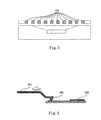
- Fig. 3 is a sectional view taking along line A-A' in Fig. 2 .
- multiple contact keys 101 may be arranged in the sound output region 202, with output holes 201 being provided between the contact keys.
- the sound output region may be decorated, but also the integration of the design may be improved, facilitating space saving.
- Fig. 4 is a schematic diagram of the connection of the contact keys and capacitive touch sensors in accordance with the embodiments of the present invention. As shown in Fig. 4 , the contact keys 101 may be connected to the capacitive touch sensors 102 via contact points 401, thereby ensuring a reliable connection.
- the sound controller 103 may generate control signals, for example, to pause, play, backward, or forward the sound, according to the changes of capacitance of different capacitive touch sensors in the multiple capacitive touch sensors.
- Figs. 5-7 show different sound control performed at different positions.
- Fig. 5 is a schematic diagram of performing the function of play/pause in accordance with the embodiments of the present invention
- Fig. 6 is a schematic diagram of performing the function of backward in accordance with the embodiments of the present invention
- Fig. 7 is a schematic diagram of performing the function of forward in accordance with the embodiments of the present invention.
- one or more contact keys located at the center may be contacted (such as single-click), such that the capacitance of one or more capacitive touch sensors 102 connected with the one or more contact keys is changed, thereby a control signal for playing sound is generated by the sound controller 103; and when the one or more contact keys are contacted by the finger 104 of the user again, the sound controller 103 may generate a control signal for pausing the sound.
- one or more contact keys located at one end may be contacted (such as single-click), such that the capacitance of one or more capacitive touch sensors 102 connected with the one or more contact keys is changed, thereby a control signal for backward of sound is generated by the sound controller 103.
- one or more contact keys located at another end may be contacted (such as single-click), such that the capacitance of one or more capacitive touch sensors connected with the one or more contact keys is changed, thereby a control signal for forward of sound is generated by the sound controller 103.
- the sound controller 103 may further control the volume of the sound according to the change of capacitance of multiple capacitive touch sensors.
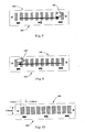
- Figs. 8 and 9 show the sound control by moving a finger 104 on multiple contact keys 101.
- Fig. 8 is a schematic diagram of performing the function of volume up in accordance with the embodiments of the present invention
- Fig. 9 is a schematic diagram of performing the function of volume down in accordance with the embodiments of the present invention.
- a user may move his finger 104 on multiple contact keys 101 from the left to the right, thereby contacting the multiple contact keys from the left to the right and changing the capacitance of multiple capacitive touch sensors 102 connected to the multiple contact keys in turn (for example, the capacitance of the capacitive touch sensor connected to the leftmost contact key is changed from low to high and again to low, and then the capacitance of the capacitive touch sensor connected to the next contact key is changed from low to high and again to low,... at last the capacitance of the capacitive touch sensor connected to the rightmost contact key is changed from low to high and again to low), and the sound controller 103 may generate a control signal for volume up according to the above changes of capacitance.
- a user may move his finger 104 on multiple contact keys 101 from the right to the left, thereby contacting the multiple contact keys from the right to the left and changing the capacitance of multiple capacitive touch sensors 102 connected to the multiple contact keys in turn (for example, the capacitance of the capacitive touch sensor connected to the rightmost contact key is changed from low to high and again to low, and then the capacitance of the capacitive touch sensor connected to the next contact key is changed from low to high and again to low,... at last the capacitance of the capacitive touch sensor connected to the leftmost contact key is changed from low to high and again to low), and the sound controller 103 may generate a control signal for volume down according to the above changes of capacitance.
- a control signal for stopping the sound may be generated after a user double clicks a contact key 101 , and particular setup modes may be determined as actually demanded.
- the user may not only control the sound by single-click or double-click, but also control the volume adjustment by moving in the sound output region, realizing the sound control like playing piano, thereby improving greatly the user experience.
- Fig. 10 is another schematic diagram of the arrangement of the contact keys 101 in accordance with the embodiments of the present invention. As shown in Fig. 10 , it is preferable that the width of each of the contact keys is 2.5mm, and the length is 8.0mm, and the width of an output hole is 1.0mm. From the viewpoint of implementation, the above setting may not only save space, but also have no effect on the implementation of functions.
- control signals for controlling the sound are generated when the contact keys are contacted and the capacitance of the capacitive touch sensors are changed, thereby improving the integration of the design, facilitating space saving, and providing better user experiences.
- the embodiments of the present invention further provide a method for sound control, applicable to a sound output region 202 of a loudspeaker, with the contents being similar to those described above, which shall not be described any further.
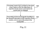
- Fig. 11 is a flowchart of the method for sound control in accordance with the embodiments of the present invention. As shown in Fig. 11 , the method for sound control includes:
- the sound controlling step 1102 includes a step of controlling the stop or muting of the sound according to the time interval of the change of the capacitance of the capacitive touch sensors.
- the contact keys 101 are multiple, with output holes 201 of the loudspeaker being provided between the contact keys; and the capacitive touch sensors 102 are multiple, with each of the capacitive touch sensors being connected to one or more of the contact keys.
- the sound controlling step 1102 includes a step of controlling the pause, play, backward or forward of the sound according to the changes of capacitance of different capacitive touch sensors 102 among the multiple capacitive touch sensors.
- the sound controlling step 1102 includes a step of controlling the volume of the sound according to the change of capacitance of the capacitive touch sensors 102.
- control signals for controlling the sound are generated when the contact keys are contacted and the capacitance of the capacitive touch sensors 102 are changed, thereby improving the integration of the design, facilitating space saving, and providing better user experiences.
- the embodiments of the present invention also provide an electronic device, which includes the sound detection device as described above.
- Fig. 12 is schematic block diagram of the electronic device 1200 in accordance with the embodiments of the present invention, which includes the above-described capacitive touch sensors 102 and sound controller 103, with the contact keys 101 being not shown in this figure.
- Such a figure is exemplary, and other types of structures may be used for supplementing or replacing this structure, so as to realized telecommunications functions or other functions.
- the electronic device 1200 includes a central processing unit 100, a communication module 110, an input unit 120, an audio processing unit 130, a memory 140, a camera 150, a display 160, and a power supply 170.
- the capacitive touch sensors 102 and sound controller 103 may be connected directly, may be connected via the central processing unit 100 shown in Fig. 12 , and may also be integrated into the central processing unit 100.
- the central processing unit 100 receives input and controls every components and operations of the electronic device 1200.
- the input unit 120 provides input to the central processing unit 100.
- the input unit 120 is, for example, a key or a touch input device.
- the camera 150 is used to pick up image data and provide the image data to the central processing unit 100, for use in a conventional manner, such as storage, and transmission, etc.
- the power supply 170 is used to supply electric power to the electronic device 1200.
- the display 160 is used to display the display objects, such as images, and characters, etc.
- the display may be, for example, an LCD display, but it is not limited thereto.
- the memory 140 is coupled to the central processing unit 100.
- the memory 140 may be a solid-state memory, such as a read-only memory (ROM), a random access memory (RAM), and a SIM card, etc. It may also be such a memory that stores information when the power is interrupted, may be optionally erased and provided with more data. Examples of such a memory are sometimes referred to as an EPROM, etc.
- the memory 140 may also be certain other types of devices.
- the memory 140 includes a buffer memory 141 (sometimes referred to as a buffer).
- the memory 140 may comprise an application/function storing portion 142 used to store application programs and function programs, or to execute the flow of the operation of the electronic device 1200 via the central processing unit 100.
- the memory 140 may further comprise a data storing portion 143 used to store data, such as a contact person, digital data, pictures, voices and/or any other data used by the electronic device.
- a driver storing portion 144 of the memory 140 may comprise various types of drivers of the electronic device for the communication function and/or for executing other functions (such as application of message transmission, and application of directory, etc.) of the electronic device.
- the communication module 110 is a transmitter/receiver 110 transmitting and receiving signals via an antenna 111.
- the communication module (transmitter/receiver) 110 is coupled to the central processing unit 100 to provide input signals and receive output signals, this being similar to the case in a conventional mobile phone.
- a plurality of communication modules 110 may be provided in the same electronic device for various communication technologies, such a cellular network module, a Bluetooth module, and/or wireless local network module, etc.
- the communication module (transmitter/receiver) 110 is also coupled to a loudspeaker 131 and a microphone 132 via the audio processing unit 130, for providing audio output via the loudspeaker 131 and receiving the audio input from the microphone 132, thereby achieving common telecommunications functions.
- the audio processing unit 130 may comprise any appropriate buffers, decoders, and amplifiers, etc.
- the audio processing unit 130 is further coupled to the central processing unit 100, thereby enabling the recording of voices in this device via the microphone 132 and the playing of the voices stored in this device via the loudspeaker 131.
- each of the parts of the present invention may be implemented by hardware, software, firmware, or a combination thereof.
- multiple steps or methods may be realized by software or firmware that is stored in the memory and executed by an appropriate instruction executing system.
- a discrete logic circuit having a logic gate circuit for realizing logic functions of data signals
- application-specific integrated circuit having an appropriate combined logic gate circuit
- PGA programmable gate array
- FPGA field programmable gate array
- logic and/or steps shown in the flowcharts or described in other manners here may be, for example, understood as a sequencing list of executable instructions for realizing logic functions, which may be implemented in any computer readable medium, for use by an instruction executing system, device or apparatus (such as a system including a computer, a system including a processor, or other systems capable of extracting instructions from an instruction executing system, device or apparatus and executing the instructions), or for use in combination with the instruction executing system, device or apparatus.
Landscapes
- Engineering & Computer Science (AREA)
- General Engineering & Computer Science (AREA)
- Theoretical Computer Science (AREA)
- Human Computer Interaction (AREA)
- Physics & Mathematics (AREA)
- General Physics & Mathematics (AREA)
- Telephone Function (AREA)
Applications Claiming Priority (2)
| Application Number | Priority Date | Filing Date | Title |
|---|---|---|---|
| CN2011102999100A CN103034376A (zh) | 2011-09-30 | 2011-09-30 | 声音控制装置、方法及电子设备 |
| US13/608,474 US20130083946A1 (en) | 2011-09-30 | 2012-09-10 | Apparatus and method for sound control and electronic service |
Publications (1)
| Publication Number | Publication Date |
|---|---|
| EP2575015A2 true EP2575015A2 (de) | 2013-04-03 |
Family
ID=47358314
Family Applications (1)
| Application Number | Title | Priority Date | Filing Date |
|---|---|---|---|
| EP12006644A Withdrawn EP2575015A2 (de) | 2011-09-30 | 2012-09-21 | Vorrichtung und Verfahren für Tonsteuerung und elektronische Geräte |
Country Status (1)
| Country | Link |
|---|---|
| EP (1) | EP2575015A2 (de) |
-
2012
- 2012-09-21 EP EP12006644A patent/EP2575015A2/de not_active Withdrawn
Non-Patent Citations (1)
| Title |
|---|
| None |
Similar Documents
| Publication | Publication Date | Title |
|---|---|---|
| US20130083946A1 (en) | Apparatus and method for sound control and electronic service | |
| US9344827B2 (en) | Method and apparatus for audio output, and electronic device | |
| US20130127778A1 (en) | Key device and electronic equipment | |
| US11457437B2 (en) | Method and apparatus for configuring information, base station and user equipment | |
| US20120313872A1 (en) | Electronic equipment, pressure detecting method and pressure detecting device | |
| CN108572696B (zh) | 一种柔性屏支撑机构、装置及移动终端 | |
| KR102085309B1 (ko) | 전자 장치에서 스크롤 장치 및 방법 | |
| EP3074861A1 (de) | Anwendungsaktivierungsverfahren und -vorrichtung sowie elektronische ausrüstung | |
| CN103559731B (zh) | 一种锁屏状态下歌词显示的方法及终端 | |
| EP2777040A1 (de) | Sprachsteuerungsvorrichtung, sprachsteuerungsverfahren und programm | |
| CN107547704A (zh) | 通话mic的切换方法、装置和移动终端 | |
| CN105791946B (zh) | 图像显示效果调整方法及装置 | |
| CN108769377A (zh) | 天线控制方法及相关产品 | |
| CN112040324A (zh) | 一种播放进度调节方法、装置、存储介质及终端 | |
| US9921796B2 (en) | Sharing of input information superimposed on images | |
| CN111597029A (zh) | 数据处理方法及装置、电子设备和存储介质 | |
| CN110874128A (zh) | 可视化数据处理方法和电子设备 | |
| CN106126170A (zh) | 一种终端的音效设置方法及终端 | |
| CN105513098B (zh) | 一种图像处理的方法和装置 | |
| CN109711830B (zh) | 二维码支付的快捷显示方法及装置、移动终端及存储介质 | |
| US8515502B2 (en) | Apparatus and method for state detection and terminal equipment | |
| CN108702764B (zh) | 物理下行控制信道监测配置、监测方法及装置和基站 | |
| KR20130040350A (ko) | 휴대단말기의 화면밝기 제어장치 및 방법 | |
| EP2575015A2 (de) | Vorrichtung und Verfahren für Tonsteuerung und elektronische Geräte | |
| CN111435907B (zh) | 传输处理方法、装置、终端和介质 |
Legal Events
| Date | Code | Title | Description |
|---|---|---|---|
| PUAI | Public reference made under article 153(3) epc to a published international application that has entered the european phase |
Free format text: ORIGINAL CODE: 0009012 |
|
| AK | Designated contracting states |
Kind code of ref document: A2 Designated state(s): AL AT BE BG CH CY CZ DE DK EE ES FI FR GB GR HR HU IE IS IT LI LT LU LV MC MK MT NL NO PL PT RO RS SE SI SK SM TR |
|
| AX | Request for extension of the european patent |
Extension state: BA ME |
|
| STAA | Information on the status of an ep patent application or granted ep patent |
Free format text: STATUS: THE APPLICATION HAS BEEN WITHDRAWN |
|
| 18W | Application withdrawn |
Effective date: 20140717 |