EP2574968A1 - Underwater connection assembly with earthing unit - Google Patents
Underwater connection assembly with earthing unit Download PDFInfo
- Publication number
- EP2574968A1 EP2574968A1 EP11306246A EP11306246A EP2574968A1 EP 2574968 A1 EP2574968 A1 EP 2574968A1 EP 11306246 A EP11306246 A EP 11306246A EP 11306246 A EP11306246 A EP 11306246A EP 2574968 A1 EP2574968 A1 EP 2574968A1
- Authority
- EP
- European Patent Office
- Prior art keywords
- sea
- earthing
- earthing electrode
- underwater
- electrode
- Prior art date
- Legal status (The legal status is an assumption and is not a legal conclusion. Google has not performed a legal analysis and makes no representation as to the accuracy of the status listed.)
- Granted
Links
- 230000003287 optical effect Effects 0.000 claims abstract description 22
- 230000006378 damage Effects 0.000 description 5
- 238000012423 maintenance Methods 0.000 description 5
- 230000008878 coupling Effects 0.000 description 3
- 238000010168 coupling process Methods 0.000 description 3
- 238000005859 coupling reaction Methods 0.000 description 3
- 239000013307 optical fiber Substances 0.000 description 3
- XLYOFNOQVPJJNP-UHFFFAOYSA-N water Substances O XLYOFNOQVPJJNP-UHFFFAOYSA-N 0.000 description 3
- 230000007257 malfunction Effects 0.000 description 2
- 238000000926 separation method Methods 0.000 description 2
- 230000003321 amplification Effects 0.000 description 1
- 230000002238 attenuated effect Effects 0.000 description 1
- 230000002950 deficient Effects 0.000 description 1
- 238000010586 diagram Methods 0.000 description 1
- 238000002955 isolation Methods 0.000 description 1
- 230000005923 long-lasting effect Effects 0.000 description 1
- 238000012544 monitoring process Methods 0.000 description 1
- 238000003199 nucleic acid amplification method Methods 0.000 description 1
Images

Classifications
-
- H—ELECTRICITY
- H01—ELECTRIC ELEMENTS
- H01R—ELECTRICALLY-CONDUCTIVE CONNECTIONS; STRUCTURAL ASSOCIATIONS OF A PLURALITY OF MUTUALLY-INSULATED ELECTRICAL CONNECTING ELEMENTS; COUPLING DEVICES; CURRENT COLLECTORS
- H01R4/00—Electrically-conductive connections between two or more conductive members in direct contact, i.e. touching one another; Means for effecting or maintaining such contact; Electrically-conductive connections having two or more spaced connecting locations for conductors and using contact members penetrating insulation
- H01R4/58—Electrically-conductive connections between two or more conductive members in direct contact, i.e. touching one another; Means for effecting or maintaining such contact; Electrically-conductive connections having two or more spaced connecting locations for conductors and using contact members penetrating insulation characterised by the form or material of the contacting members
- H01R4/66—Connections with the terrestrial mass, e.g. earth plate, earth pin
-
- G—PHYSICS
- G02—OPTICS
- G02B—OPTICAL ELEMENTS, SYSTEMS OR APPARATUS
- G02B6/00—Light guides; Structural details of arrangements comprising light guides and other optical elements, e.g. couplings
- G02B6/44—Mechanical structures for providing tensile strength and external protection for fibres, e.g. optical transmission cables
- G02B6/4401—Optical cables
- G02B6/4415—Cables for special applications
- G02B6/4427—Pressure resistant cables, e.g. undersea cables
- G02B6/4428—Penetrator systems in pressure-resistant devices
Definitions
- the present invention relates to an underwater connection assembly for use in underwater communication systems such as submarine optical telecommunication systems.
- cables are typically laid in water in order to connect a first terminal station to a second terminal station.
- a cable may be used for conveying significant amount of data between the two terminal stations while delivering power to the submerged amplifiers from the terminal stations.
- Such cables are typically referred to as trunk cables or simply trunk..
- the cable segment is a repeatered segment which typically allows for the reconfiguration of the powering path.
- a repeatered segment it is typically meant to refer to a segment of underwater optical cable in which one or more repeaters are used along the length of the optical cable in order to amplify the optical signal which may have been attenuated as a result of travelling a certain distance in the segment.
- the additional segments are then safely terminated in the land station typically via a cable termination cubicle of the power feed equipment.
- un-repeatered segments may be used.
- the power needed in order to operate on that segment is typically provided by the land station or the offshore station directly connected to the segment.
- the voltage present on the trunk cable is typically high (up to 12 to 15 KV), it is desirable to avoid circumstances in which the voltage present on the trunk may be applied to the termination of the segment, even when the branching units are reconfigured to switch off during cable maintenance operations.
- one known solution is to provide a permanent connection from a branch cable of the branching unit to which said segment is connected, to the sea earth. This is typically done at or close to the branching unit, typically by means of a sea electrode.
- This solution presents a drawback because often a firm and long-lasting contact of the sea electrode to the sea bed may not be always ensured thus causing a failure in such sea earthing.
- One cause of such failure may be that the sea electrode is defective and/or it is isolated from the branching unit. In such case, the branching unit is disconnected from the sea earth and it may not be possible to guarantee the safety of the system.
- the branching unit is configured such that no electrical connection exists between the trunk cable and the terminal station in order to avoid presence of unwanted high voltage at the terminal station.
- the voltage from the trunk may be applied to the terminal station through the segment. Therefore if the earth connection fails, the above-mentioned high voltages (10 KV or higher) from the trunk may appear at the terminal station. This may be dangerous because at such instances, operating personnel may be in contact with the terminal station for example performing maintenance operations (often referred to as electroding), which may result in personal injuries and/or significant damages to the land or offshore platforms (for example, if the accidental presence of high voltage generates sparks).
- electroding maintenance operations
- Some embodiments of the present disclosure feature an underwater connection assembly comprising an underwater device and an optical cable segment configured for conveying electrical and optical signals to and from a terminal station, wherein the optical cable segment is configured to be coupled to a first sea earth by means of a first sea earthing electrode and the underwater device is configured to be coupled to a second sea earth by means of a second sea earthing electrode and wherein, in use, the first sea earthing electrode and the second sea earthing electrode are disposed at separated locations from each other.
- the first sea earthing electrode and the second sea earthing electrode are separated from each other by mean of a sea earthing unit, wherein the sea earthing unit is configured to maintain the first sea earthing electrode and the second sea earthing electrode separated from each other.
- Some embodiments of the present disclosure relate to a submarine optical telecommunication system comprising the underwater connection assembly as featured herein.
- the submarine optical telecommunication system comprises an underwater oil and gas communication network.
- connection elements that are relevant for understanding the present disclosure.
- connection elements for example optical fibers used for transmitting optical signals and/or electric cables used for conveying electric power are not shown although these elements may be present and necessary for the operation of the devices recited herein.
- FIGS. 1 a and 1 b exemplary schematic representations of two configurations of a known underwater device are shown. Like elements in these figures have like reference numerals.
- the underwater device may be for example a submarine branching unit.
- a submarine branching unit by way of non-limiting example.
- Figure 1 a shows an underwater branching unit 10 which is coupled to a trunk cable (or trunk) 11.
- a terminal station 12 for example a land station or an offshore platform, is coupled to the branching unit 10 by means of a branch cable (or cable segment) 13.
- the cable segment may be an optical cable, comprising (although not shown) optical fibers for carrying optical signals and electrical cables for conveying electric power.
- a first configuration of the branching unit 10 is shown in which the trunk 11 is coupled to port A and port B, and the branch cable 13 is connected to a sea earth by means of a sea earthing electrode 14.
- the sea earth electrode 14 does not make a reliable contact to the sea earth.
- the branching unit 10 switches the trunk voltage onto the branch cable 13, this voltage will become present at the terminal station 12 which would give rise to significant danger for the personnel operating at the terminal station, for example performing maintenance work, or would lead to significant damage to the equipment at the terminal station 12.
- Figure 1b shows a different scenario of configuration of the branching unit 10 in which the trunk 11, coupled to port A and port B, and the branch cable 13 are all connected to a sea earth by means of the sea earthing electrode 14.
- connection assembly 2 shows an exemplary schematic representation of an underwater connection assembly according to some embodiments of the present disclosure.
- the connection assembly 2 comprises an underwater device, which by way of non-limiting example may be a branching unit 20 which is coupled to a trunk 21.
- a terminal station 22 for example a land station or an offshore platform, is coupled to the branching unit 20 by means of a set of branch cables (or cable segments) 23 and 24 as will be further described below.
- the cable segments may be optical cables, comprising (although not shown) optical fibers for carrying optical signals and electrical cables for conveying electric power.
- the coupling between the terminal station 22 and the branching unit 20 comprises a first branch cable 23 connected to the terminal station 22 at one end and to a first sea earth by means of a first sea earthing electrode 25 at the other end; and a second branch cable 24 connected to the branching unit 20 at one end and a second sea earth by means of a second sea earthing electrode 26 at the other end.
- the first sea earthing electrode 25 and the second sea earthing electrode 26 are separated from each other thereby no electric contact is present between the two earthing electrodes.
- the trunk 21 is coupled to port A and port B and the branch cable 24 is connected to a third sea earth by means of a third sea earthing electrode 27.
- first sea earthing electrode 25 and the second sea earthing electrode 26 are electrically separated form each other and are disposed at separate locations at a convenient distant form each other in order eliminate or substantially reduce a risk of electrical coupling between the two sea earthing electrodes through the water.
- An example of a convenient distant may be 10 meters or higher.
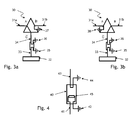
- Figure 3a shows a first scenario in the branching unit 30 in which a first segment 31 a of the trunk is coupled, through port A, port C and branch cable segment 34 to the sea earthing electrode 36, a second segment 31 b of the trunk is coupled, through port B to the sea earthing electrode 37 and the terminal station 32 is coupled through the branch cable segment 33 to the sea earthing electrode 35.
- Figure 3b shows a second scenario in the branching unit 30 in which the first segment 31 a of the trunk is coupled, through port A to the sea earthing electrode 38, a second segment 31 b of the trunk is coupled, through port B, port C and branch cable segment 34 to the sea earthing electrode 36, and the terminal station 32 is coupled through the branch cable segment 33 to the sea earthing electrode 35.
- respective ends of the branch cable 23 and the branch cable 24 are incorporated in a sea earthing unit 28.
- the sea earthing unit is intended to maintain a physical separation between the first sea earthing electrode 25 and the second sea earthing electrode 26 so as to provide a secure isolation between the two electrodes.
- FIG 4 shows an exemplary schematic representation of a sea earthing unit in the connection assembly of figure 2 .
- the sea earthing unit 40 incorporates an end 41 of a first branch cable segment, for example the segment coupled to the terminal station, and an end 43 of a second branch cable segment, for example the segment coupled to the branching unit.
- the end 41 of the first branching cable segment is coupled to a first earthing electrode 42 which is secured to the sea earthing unit 40 at one end, and the end 43 of the second branching cable segment is coupled to a second earthing electrode 44 which is secured to the sea earthing unit 40 at another end such that a distance is ensured between the first earthing electrode 42 and a second earthing electrode 44 which is sufficient to avoid, or substantially reduce, a risk of electrical coupling between the two sea earthing electrodes through the water.
- the sea earthing unit 40 comprises an element 45 (for instance a resistor) disposed between the end 41 of the first branching cable segment and the first earthing electrode 42 to facilitate the continuity monitoring of the branch from the land station or offshore platform.
- This element may be installed inside the sea earthing unit 40.
Abstract
Description
- The present invention relates to an underwater connection assembly for use in underwater communication systems such as submarine optical telecommunication systems.
- In underwater communication systems, cables are typically laid in water in order to connect a first terminal station to a second terminal station. In such systems a cable may be used for conveying significant amount of data between the two terminal stations while delivering power to the submerged amplifiers from the terminal stations. Such cables are typically referred to as trunk cables or simply trunk..
- In submarine optical telecommunication systems there are circumstances where it may be needed to connect several land stations or offshore platforms to the trunk. Typically, this is done by using additional segments of cable in order to connect a land station to the trunk. The cable segment is typically connected to the trunk by means of a branching unit.
- In many occasions the cable segment is a repeatered segment which typically allows for the reconfiguration of the powering path. By a repeatered segment, it is typically meant to refer to a segment of underwater optical cable in which one or more repeaters are used along the length of the optical cable in order to amplify the optical signal which may have been attenuated as a result of travelling a certain distance in the segment.
- The additional segments are then safely terminated in the land station typically via a cable termination cubicle of the power feed equipment.
- On the other hand, in some circumstances where the length of the additional segment is not long enough to justify the use of amplifiers or, where the network is intended for interconnecting offshore platforms to the land stations without the need of amplification, un-repeatered segments may be used.
- In the absence of repeaters on the segment, the power needed in order to operate on that segment is typically provided by the land station or the offshore station directly connected to the segment.
- As the voltage present on the trunk cable is typically high (up to 12 to 15 KV), it is desirable to avoid circumstances in which the voltage present on the trunk may be applied to the termination of the segment, even when the branching units are reconfigured to switch off during cable maintenance operations.
- In order to avoid a situation where the voltage on the trunk is applied to the terminal station through a branching unit and the segment connecting the branching unit to the terminal station, one known solution is to provide a permanent connection from a branch cable of the branching unit to which said segment is connected, to the sea earth. This is typically done at or close to the branching unit, typically by means of a sea electrode. This solution however presents a drawback because often a firm and long-lasting contact of the sea electrode to the sea bed may not be always ensured thus causing a failure in such sea earthing. One cause of such failure may be that the sea electrode is defective and/or it is isolated from the branching unit. In such case, the branching unit is disconnected from the sea earth and it may not be possible to guarantee the safety of the system. Typically when maintenance operation is performed at the terminal station (land station or offshore platform) the branching unit is configured such that no electrical connection exists between the trunk cable and the terminal station in order to avoid presence of unwanted high voltage at the terminal station.
- However, if during such maintenance operations, a malfunctioning of the branching unit occurs, the voltage from the trunk may be applied to the terminal station through the segment. Therefore if the earth connection fails, the above-mentioned high voltages (10 KV or higher) from the trunk may appear at the terminal station. This may be dangerous because at such instances, operating personnel may be in contact with the terminal station for example performing maintenance operations (often referred to as electroding), which may result in personal injuries and/or significant damages to the land or offshore platforms (for example, if the accidental presence of high voltage generates sparks).
- Some embodiments of the present disclosure feature an underwater connection assembly comprising an underwater device and an optical cable segment configured for conveying electrical and optical signals to and from a terminal station, wherein the optical cable segment is configured to be coupled to a first sea earth by means of a first sea earthing electrode and the underwater device is configured to be coupled to a second sea earth by means of a second sea earthing electrode and wherein, in use, the first sea earthing electrode and the second sea earthing electrode are disposed at separated locations from each other.
- According to some specific embodiments, in use, the first sea earthing electrode and the second sea earthing electrode are separated from each other by mean of a sea earthing unit, wherein the sea earthing unit is configured to maintain the first sea earthing electrode and the second sea earthing electrode separated from each other.
- Some embodiments of the present disclosure relate to a submarine optical telecommunication system comprising the underwater connection assembly as featured herein.
- According to some specific embodiments, the submarine optical telecommunication system comprises an underwater oil and gas communication network.
- These and further features and advantages of the present invention are described in more detail, for the purpose of illustration and not limitation, in the following description as well as in the claims with the aid of the accompanying drawings.
-
-
Figures 1 a and 1 b are exemplary schematic representations of two connection configurations of a known underwater device. -
Figure 2 is an exemplary schematic representation of an underwater connection assembly according to some embodiments. -
Figures 3a and 3b are exemplary schematic representations of various connection scenarios of the underwater connection assembly offigure 2 . -
Figure 4 is an exemplary schematic representation in some detail of a sea earthing unit configured for use in the connection assembly offigure 2 . - It is to be noted that, for the sake of simplicity, the drawings are intended to mainly show the connection elements that are relevant for understanding the present disclosure. Those skilled in the related art will realize that other connection elements, for example optical fibers used for transmitting optical signals and/or electric cables used for conveying electric power are not shown although these elements may be present and necessary for the operation of the devices recited herein.
- In
figures 1 a and 1 b exemplary schematic representations of two configurations of a known underwater device are shown. Like elements in these figures have like reference numerals. The underwater device may be for example a submarine branching unit. In the following description, reference is made to a submarine branching unit by way of non-limiting example. -
Figure 1 a shows anunderwater branching unit 10 which is coupled to a trunk cable (or trunk) 11. Aterminal station 12, for example a land station or an offshore platform, is coupled to the branchingunit 10 by means of a branch cable (or cable segment) 13. The cable segment may be an optical cable, comprising (although not shown) optical fibers for carrying optical signals and electrical cables for conveying electric power. In the scenario offigure 1a , a first configuration of thebranching unit 10 is shown in which thetrunk 11 is coupled to port A and port B, and thebranch cable 13 is connected to a sea earth by means of asea earthing electrode 14. However, as mentioned above, situations may occur that thesea earth electrode 14 does not make a reliable contact to the sea earth. In such conditions, if by error or malfunction, thebranching unit 10 switches the trunk voltage onto thebranch cable 13, this voltage will become present at theterminal station 12 which would give rise to significant danger for the personnel operating at the terminal station, for example performing maintenance work, or would lead to significant damage to the equipment at theterminal station 12. -
Figure 1b shows a different scenario of configuration of thebranching unit 10 in which thetrunk 11, coupled to port A and port B, and thebranch cable 13 are all connected to a sea earth by means of thesea earthing electrode 14. - Other configurations are also possible but not described herein as they are considered not relevant for the understanding of the present specification.
-
Figure 2 shows an exemplary schematic representation of an underwater connection assembly according to some embodiments of the present disclosure. The connection assembly 2 comprises an underwater device, which by way of non-limiting example may be abranching unit 20 which is coupled to atrunk 21. Aterminal station 22, for example a land station or an offshore platform, is coupled to the branchingunit 20 by means of a set of branch cables (or cable segments) 23 and 24 as will be further described below. The cable segments may be optical cables, comprising (although not shown) optical fibers for carrying optical signals and electrical cables for conveying electric power. - As shown in the figure the coupling between the
terminal station 22 and thebranching unit 20 comprises afirst branch cable 23 connected to theterminal station 22 at one end and to a first sea earth by means of a firstsea earthing electrode 25 at the other end; and asecond branch cable 24 connected to the branchingunit 20 at one end and a second sea earth by means of a secondsea earthing electrode 26 at the other end. As shown in the figure, the firstsea earthing electrode 25 and the secondsea earthing electrode 26 are separated from each other thereby no electric contact is present between the two earthing electrodes. - In the particular scenario of
figure 2 , thetrunk 21 is coupled to port A and port B and thebranch cable 24 is connected to a third sea earth by means of a thirdsea earthing electrode 27. - With this arrangement, in case the
sea earth electrode 27 does not make a reliable contact to the sea earth the dangers and risk of damages as discussed in the case offigure 1a would not exist anymore, because even if by error or malfunction, thebranching unit 20 switches the trunk voltage onto thebranch cable 13, this voltage will not be coupled to theterminal station 22 because of the existence of the secondsea earthing electrode 26 which would provide a safe earth connection at the end of thebranch cable 24. Furthermore, the presence of physical separation between thefirst branch cable 23 and the second branch cable 24) and of the firstsea earthing electrode 25 at the end ofbranch cable 23 ensure a further factor of safety and security. - Yet as an additional factor of safety and security, the first
sea earthing electrode 25 and the secondsea earthing electrode 26 are electrically separated form each other and are disposed at separate locations at a convenient distant form each other in order eliminate or substantially reduce a risk of electrical coupling between the two sea earthing electrodes through the water. An example of a convenient distant may be 10 meters or higher. -
Figure 3a shows a first scenario in thebranching unit 30 in which afirst segment 31 a of the trunk is coupled, through port A, port C andbranch cable segment 34 to thesea earthing electrode 36, asecond segment 31 b of the trunk is coupled, through port B to thesea earthing electrode 37 and theterminal station 32 is coupled through thebranch cable segment 33 to thesea earthing electrode 35. -
Figure 3b shows a second scenario in thebranching unit 30 in which thefirst segment 31 a of the trunk is coupled, through port A to thesea earthing electrode 38, asecond segment 31 b of the trunk is coupled, through port B, port C andbranch cable segment 34 to thesea earthing electrode 36, and theterminal station 32 is coupled through thebranch cable segment 33 to thesea earthing electrode 35. - Here again, the use of the two physically separated
sea earthing electrodes - Preferably, respective ends of the
branch cable 23 and thebranch cable 24 are incorporated in asea earthing unit 28. The sea earthing unit is intended to maintain a physical separation between the firstsea earthing electrode 25 and the secondsea earthing electrode 26 so as to provide a secure isolation between the two electrodes. -
Figure 4 shows an exemplary schematic representation of a sea earthing unit in the connection assembly offigure 2 . As shown in the figure, thesea earthing unit 40 incorporates anend 41 of a first branch cable segment, for example the segment coupled to the terminal station, and anend 43 of a second branch cable segment, for example the segment coupled to the branching unit. Theend 41 of the first branching cable segment is coupled to a first earthingelectrode 42 which is secured to thesea earthing unit 40 at one end, and theend 43 of the second branching cable segment is coupled to asecond earthing electrode 44 which is secured to thesea earthing unit 40 at another end such that a distance is ensured between the first earthingelectrode 42 and asecond earthing electrode 44 which is sufficient to avoid, or substantially reduce, a risk of electrical coupling between the two sea earthing electrodes through the water. - Preferably the
sea earthing unit 40 comprises an element 45 (for instance a resistor) disposed between theend 41 of the first branching cable segment and the first earthingelectrode 42 to facilitate the continuity monitoring of the branch from the land station or offshore platform. This element may be installed inside thesea earthing unit 40. - The various embodiments of the present invention may be combined as long as such combination is compatible and/or complimentary.
- Further it is to be noted that the list of structures corresponding to the claimed means is not exhaustive and that one skilled in the art understands that equivalent structures can be substituted for the recited structure without departing from the scope of the invention.
- It should be appreciated by those skilled in the art that any block diagrams herein represent conceptual views of illustrative circuitry embodying the principles of the invention.
Claims (5)
- An underwater connection assembly comprising an underwater device and an optical cable segment configured for conveying electrical and optical signals to or from a terminal station, wherein the optical cable segment is configured to be coupled to a first sea earth by means of a first sea earthing electrode and the underwater device is configured to be coupled to a second sea earth by means of a second sea earthing electrode and wherein, in use, the first sea earthing electrode and the second sea earthing electrode are disposed at separated locations from each other.
- The underwater connection assembly of claim 1 wherein, in use, the first sea earthing electrode and the second sea earthing electrode are separated from each other by mean of a sea earthing unit, wherein the sea earthing unit is configured to maintain the first sea earthing electrode and the second sea earthing electrode separated from each other.
- The underwater connection assembly of claim 1 or claim 2 wherein the underwater device is a submarine branching unit.
- A submarine optical telecommunication system comprising the underwater connection assembly of any one of claims 1 to claim 3.
- The submarine optical telecommunication system of claim 4 comprising an underwater oil and gas communication network.
Priority Applications (6)
| Application Number | Priority Date | Filing Date | Title |
|---|---|---|---|
| EP11306246.7A EP2574968B1 (en) | 2011-09-29 | 2011-09-29 | Underwater connection assembly with earthing unit |
| KR1020147010994A KR101661500B1 (en) | 2011-09-29 | 2012-09-19 | Underwater connection assembly with earthing unit |
| JP2014532319A JP5969035B2 (en) | 2011-09-29 | 2012-09-19 | Underwater connection assembly |
| CN201280046651.3A CN103827720B (en) | 2011-09-29 | 2012-09-19 | Coupling assembly under water with ground unit |
| US14/347,681 US9196974B2 (en) | 2011-09-29 | 2012-09-19 | Underwater connection assembly for use in underwater communication systems |
| PCT/EP2012/068389 WO2013045320A1 (en) | 2011-09-29 | 2012-09-19 | Underwater connection assembly with earthing unit |
Applications Claiming Priority (1)
| Application Number | Priority Date | Filing Date | Title |
|---|---|---|---|
| EP11306246.7A EP2574968B1 (en) | 2011-09-29 | 2011-09-29 | Underwater connection assembly with earthing unit |
Publications (2)
| Publication Number | Publication Date |
|---|---|
| EP2574968A1 true EP2574968A1 (en) | 2013-04-03 |
| EP2574968B1 EP2574968B1 (en) | 2019-04-10 |
Family
ID=46875829
Family Applications (1)
| Application Number | Title | Priority Date | Filing Date |
|---|---|---|---|
| EP11306246.7A Active EP2574968B1 (en) | 2011-09-29 | 2011-09-29 | Underwater connection assembly with earthing unit |
Country Status (6)
| Country | Link |
|---|---|
| US (1) | US9196974B2 (en) |
| EP (1) | EP2574968B1 (en) |
| JP (1) | JP5969035B2 (en) |
| KR (1) | KR101661500B1 (en) |
| CN (1) | CN103827720B (en) |
| WO (1) | WO2013045320A1 (en) |
Families Citing this family (3)
| Publication number | Priority date | Publication date | Assignee | Title |
|---|---|---|---|---|
| US10355744B2 (en) * | 2014-12-10 | 2019-07-16 | Nec Corporation | Feed line branching apparatus and feed line branching method |
| US10461852B1 (en) | 2018-08-07 | 2019-10-29 | Facebook, Inc. | Submarine cable network architecture |
| CN111082259B (en) * | 2019-11-20 | 2021-02-02 | 烽火海洋网络设备有限公司 | Far-end grounding electrode structure for submarine equipment |
Citations (7)
| Publication number | Priority date | Publication date | Assignee | Title |
|---|---|---|---|---|
| JPS6158419A (en) * | 1984-07-26 | 1986-03-25 | 富士通株式会社 | Earth structure |
| JPH01201610A (en) * | 1988-02-08 | 1989-08-14 | Fujitsu Ltd | Connecting structure for optical submarine cable |
| WO1994018732A1 (en) * | 1993-02-02 | 1994-08-18 | Cable & Wireless (Marine) Limited | Repairs to repeatered submarine communication cables |
| WO2000038291A1 (en) * | 1998-12-22 | 2000-06-29 | Ccs Technology, Inc. | Cable system for use in hazardous environments |
| EP1312962A2 (en) * | 2001-10-31 | 2003-05-21 | Alcatel | Earthing electrode assembly for submerged electrical apparatus |
| GB2463487A (en) * | 2008-09-15 | 2010-03-17 | Viper Subsea Ltd | Subsea protection device |
| EP2209175A1 (en) * | 2008-12-19 | 2010-07-21 | OpenHydro IP Limited | A method of installing a hydroelectric turbine generator |
Family Cites Families (8)
| Publication number | Priority date | Publication date | Assignee | Title |
|---|---|---|---|---|
| US2440963A (en) * | 1945-03-06 | 1948-05-04 | Richard W Luce | Method of making molds |
| US4799825A (en) * | 1983-12-08 | 1989-01-24 | Meyerhoff Shirley B | Oil transfer system |
| JPS60249105A (en) * | 1984-05-25 | 1985-12-09 | Kokusai Denshin Denwa Co Ltd <Kdd> | Construction for detaining optical submarine cable |
| JP2595287B2 (en) | 1988-02-29 | 1997-04-02 | 日本電信電話株式会社 | Submarine cable with earth electrode for underwater branching equipment |
| JP2624499B2 (en) | 1988-02-29 | 1997-06-25 | 日本電信電話株式会社 | Power supply branch switching method and switching device for submarine cable transmission line |
| JPH0224909A (en) * | 1988-07-14 | 1990-01-26 | Fujitsu Ltd | Submarine cable |
| JP3387614B2 (en) | 1994-03-17 | 2003-03-17 | 富士通株式会社 | Underwater branching equipment power supply switching circuit |
| JP3341245B2 (en) * | 1995-12-21 | 2002-11-05 | ケイディーディーアイ株式会社 | Power supply line switching circuit |
-
2011
- 2011-09-29 EP EP11306246.7A patent/EP2574968B1/en active Active
-
2012
- 2012-09-19 JP JP2014532319A patent/JP5969035B2/en active Active
- 2012-09-19 CN CN201280046651.3A patent/CN103827720B/en active Active
- 2012-09-19 US US14/347,681 patent/US9196974B2/en active Active
- 2012-09-19 KR KR1020147010994A patent/KR101661500B1/en active IP Right Grant
- 2012-09-19 WO PCT/EP2012/068389 patent/WO2013045320A1/en active Application Filing
Patent Citations (7)
| Publication number | Priority date | Publication date | Assignee | Title |
|---|---|---|---|---|
| JPS6158419A (en) * | 1984-07-26 | 1986-03-25 | 富士通株式会社 | Earth structure |
| JPH01201610A (en) * | 1988-02-08 | 1989-08-14 | Fujitsu Ltd | Connecting structure for optical submarine cable |
| WO1994018732A1 (en) * | 1993-02-02 | 1994-08-18 | Cable & Wireless (Marine) Limited | Repairs to repeatered submarine communication cables |
| WO2000038291A1 (en) * | 1998-12-22 | 2000-06-29 | Ccs Technology, Inc. | Cable system for use in hazardous environments |
| EP1312962A2 (en) * | 2001-10-31 | 2003-05-21 | Alcatel | Earthing electrode assembly for submerged electrical apparatus |
| GB2463487A (en) * | 2008-09-15 | 2010-03-17 | Viper Subsea Ltd | Subsea protection device |
| EP2209175A1 (en) * | 2008-12-19 | 2010-07-21 | OpenHydro IP Limited | A method of installing a hydroelectric turbine generator |
Also Published As
| Publication number | Publication date |
|---|---|
| KR20140074962A (en) | 2014-06-18 |
| CN103827720B (en) | 2017-05-31 |
| JP2014534664A (en) | 2014-12-18 |
| WO2013045320A1 (en) | 2013-04-04 |
| EP2574968B1 (en) | 2019-04-10 |
| US9196974B2 (en) | 2015-11-24 |
| JP5969035B2 (en) | 2016-08-10 |
| US20140238716A1 (en) | 2014-08-28 |
| KR101661500B1 (en) | 2016-09-30 |
| CN103827720A (en) | 2014-05-28 |
Similar Documents
| Publication | Publication Date | Title |
|---|---|---|
| EP2738959B1 (en) | System and method for providing underwater communication data | |
| EP2393220B1 (en) | Undersea optical and electrical distribution apparatus | |
| EP2393222A1 (en) | System and method for transporting electric power and providing optical fiber communications under sea water | |
| US10263712B2 (en) | Submarine optical cable shore landing apparatus | |
| CN107005269B (en) | Feeder branching device and feeder branching method | |
| EP2393221B1 (en) | Undersea power distribution system | |
| US9196974B2 (en) | Underwater connection assembly for use in underwater communication systems | |
| US10230456B2 (en) | Branching configuration including a cross-coupling arrangement to provide fault tolerance and topside recovery in the event of subsea umbilical assembly failure and system and method including same | |
| CN111817245A (en) | Branching unit for power distribution | |
| CN111133684B (en) | Subsea branching unit and subsea branching method | |
| EP2728765A2 (en) | Power feeding path switching device and power feeding system | |
| EP1294113B1 (en) | Branching unit for an optical transmission system | |
| Thomas et al. | Data transmission and electrical powering flexibility for cabled ocean observatories | |
| Waterworth | Industrial solutions for regional cabled ocean observatories | |
| Thomas et al. | Extending the reach of cabled ocean observatories | |
| Bizarria et al. | Technique applied in electrical power distribution for Satellite Launch Vehicle |
Legal Events
| Date | Code | Title | Description |
|---|---|---|---|
| PUAI | Public reference made under article 153(3) epc to a published international application that has entered the european phase |
Free format text: ORIGINAL CODE: 0009012 |
|
| AK | Designated contracting states |
Kind code of ref document: A1 Designated state(s): AL AT BE BG CH CY CZ DE DK EE ES FI FR GB GR HR HU IE IS IT LI LT LU LV MC MK MT NL NO PL PT RO RS SE SI SK SM TR |
|
| AX | Request for extension of the european patent |
Extension state: BA ME |
|
| 111Z | Information provided on other rights and legal means of execution |
Free format text: AL AT BE BG CH CY CZ DE DK EE ES FI FR GB GR HR HU IE IS IT LI LT LU LV MC MK MT NL NO PL PT RO RS SE SI SK SM TR Effective date: 20130410 |
|
| 17P | Request for examination filed |
Effective date: 20131004 |
|
| RBV | Designated contracting states (corrected) |
Designated state(s): AL AT BE BG CH CY CZ DE DK EE ES FI FR GB GR HR HU IE IS IT LI LT LU LV MC MK MT NL NO PL PT RO RS SE SI SK SM TR |
|
| RAP1 | Party data changed (applicant data changed or rights of an application transferred) |
Owner name: ALCATEL LUCENT |
|
| D11X | Information provided on other rights and legal means of execution (deleted) | ||
| 17Q | First examination report despatched |
Effective date: 20160315 |
|
| RAP1 | Party data changed (applicant data changed or rights of an application transferred) |
Owner name: ALCATEL LUCENT |
|
| GRAP | Despatch of communication of intention to grant a patent |
Free format text: ORIGINAL CODE: EPIDOSNIGR1 |
|
| STAA | Information on the status of an ep patent application or granted ep patent |
Free format text: STATUS: GRANT OF PATENT IS INTENDED |
|
| RIC1 | Information provided on ipc code assigned before grant |
Ipc: G02B 6/44 20060101AFI20180927BHEP Ipc: H01R 4/66 20060101ALI20180927BHEP |
|
| INTG | Intention to grant announced |
Effective date: 20181016 |
|
| GRAS | Grant fee paid |
Free format text: ORIGINAL CODE: EPIDOSNIGR3 |
|
| GRAA | (expected) grant |
Free format text: ORIGINAL CODE: 0009210 |
|
| STAA | Information on the status of an ep patent application or granted ep patent |
Free format text: STATUS: THE PATENT HAS BEEN GRANTED |
|
| AK | Designated contracting states |
Kind code of ref document: B1 Designated state(s): AL AT BE BG CH CY CZ DE DK EE ES FI FR GB GR HR HU IE IS IT LI LT LU LV MC MK MT NL NO PL PT RO RS SE SI SK SM TR |
|
| REG | Reference to a national code |
Ref country code: GB Ref legal event code: FG4D |
|
| REG | Reference to a national code |
Ref country code: CH Ref legal event code: EP Ref country code: AT Ref legal event code: REF Ref document number: 1119497 Country of ref document: AT Kind code of ref document: T Effective date: 20190415 |
|
| REG | Reference to a national code |
Ref country code: DE Ref legal event code: R096 Ref document number: 602011057913 Country of ref document: DE |
|
| REG | Reference to a national code |
Ref country code: IE Ref legal event code: FG4D |
|
| REG | Reference to a national code |
Ref country code: NL Ref legal event code: MP Effective date: 20190410 |
|
| REG | Reference to a national code |
Ref country code: LT Ref legal event code: MG4D |
|
| REG | Reference to a national code |
Ref country code: AT Ref legal event code: MK05 Ref document number: 1119497 Country of ref document: AT Kind code of ref document: T Effective date: 20190410 |
|
| PG25 | Lapsed in a contracting state [announced via postgrant information from national office to epo] |
Ref country code: NL Free format text: LAPSE BECAUSE OF FAILURE TO SUBMIT A TRANSLATION OF THE DESCRIPTION OR TO PAY THE FEE WITHIN THE PRESCRIBED TIME-LIMIT Effective date: 20190410 |
|
| PG25 | Lapsed in a contracting state [announced via postgrant information from national office to epo] |
Ref country code: NO Free format text: LAPSE BECAUSE OF FAILURE TO SUBMIT A TRANSLATION OF THE DESCRIPTION OR TO PAY THE FEE WITHIN THE PRESCRIBED TIME-LIMIT Effective date: 20190710 Ref country code: FI Free format text: LAPSE BECAUSE OF FAILURE TO SUBMIT A TRANSLATION OF THE DESCRIPTION OR TO PAY THE FEE WITHIN THE PRESCRIBED TIME-LIMIT Effective date: 20190410 Ref country code: LT Free format text: LAPSE BECAUSE OF FAILURE TO SUBMIT A TRANSLATION OF THE DESCRIPTION OR TO PAY THE FEE WITHIN THE PRESCRIBED TIME-LIMIT Effective date: 20190410 Ref country code: SE Free format text: LAPSE BECAUSE OF FAILURE TO SUBMIT A TRANSLATION OF THE DESCRIPTION OR TO PAY THE FEE WITHIN THE PRESCRIBED TIME-LIMIT Effective date: 20190410 Ref country code: PT Free format text: LAPSE BECAUSE OF FAILURE TO SUBMIT A TRANSLATION OF THE DESCRIPTION OR TO PAY THE FEE WITHIN THE PRESCRIBED TIME-LIMIT Effective date: 20190910 Ref country code: HR Free format text: LAPSE BECAUSE OF FAILURE TO SUBMIT A TRANSLATION OF THE DESCRIPTION OR TO PAY THE FEE WITHIN THE PRESCRIBED TIME-LIMIT Effective date: 20190410 Ref country code: ES Free format text: LAPSE BECAUSE OF FAILURE TO SUBMIT A TRANSLATION OF THE DESCRIPTION OR TO PAY THE FEE WITHIN THE PRESCRIBED TIME-LIMIT Effective date: 20190410 Ref country code: AL Free format text: LAPSE BECAUSE OF FAILURE TO SUBMIT A TRANSLATION OF THE DESCRIPTION OR TO PAY THE FEE WITHIN THE PRESCRIBED TIME-LIMIT Effective date: 20190410 |
|
| PG25 | Lapsed in a contracting state [announced via postgrant information from national office to epo] |
Ref country code: BG Free format text: LAPSE BECAUSE OF FAILURE TO SUBMIT A TRANSLATION OF THE DESCRIPTION OR TO PAY THE FEE WITHIN THE PRESCRIBED TIME-LIMIT Effective date: 20190710 Ref country code: LV Free format text: LAPSE BECAUSE OF FAILURE TO SUBMIT A TRANSLATION OF THE DESCRIPTION OR TO PAY THE FEE WITHIN THE PRESCRIBED TIME-LIMIT Effective date: 20190410 Ref country code: PL Free format text: LAPSE BECAUSE OF FAILURE TO SUBMIT A TRANSLATION OF THE DESCRIPTION OR TO PAY THE FEE WITHIN THE PRESCRIBED TIME-LIMIT Effective date: 20190410 Ref country code: RS Free format text: LAPSE BECAUSE OF FAILURE TO SUBMIT A TRANSLATION OF THE DESCRIPTION OR TO PAY THE FEE WITHIN THE PRESCRIBED TIME-LIMIT Effective date: 20190410 Ref country code: GR Free format text: LAPSE BECAUSE OF FAILURE TO SUBMIT A TRANSLATION OF THE DESCRIPTION OR TO PAY THE FEE WITHIN THE PRESCRIBED TIME-LIMIT Effective date: 20190711 |
|
| PG25 | Lapsed in a contracting state [announced via postgrant information from national office to epo] |
Ref country code: IS Free format text: LAPSE BECAUSE OF FAILURE TO SUBMIT A TRANSLATION OF THE DESCRIPTION OR TO PAY THE FEE WITHIN THE PRESCRIBED TIME-LIMIT Effective date: 20190810 Ref country code: AT Free format text: LAPSE BECAUSE OF FAILURE TO SUBMIT A TRANSLATION OF THE DESCRIPTION OR TO PAY THE FEE WITHIN THE PRESCRIBED TIME-LIMIT Effective date: 20190410 |
|
| REG | Reference to a national code |
Ref country code: DE Ref legal event code: R097 Ref document number: 602011057913 Country of ref document: DE |
|
| PG25 | Lapsed in a contracting state [announced via postgrant information from national office to epo] |
Ref country code: SK Free format text: LAPSE BECAUSE OF FAILURE TO SUBMIT A TRANSLATION OF THE DESCRIPTION OR TO PAY THE FEE WITHIN THE PRESCRIBED TIME-LIMIT Effective date: 20190410 Ref country code: DK Free format text: LAPSE BECAUSE OF FAILURE TO SUBMIT A TRANSLATION OF THE DESCRIPTION OR TO PAY THE FEE WITHIN THE PRESCRIBED TIME-LIMIT Effective date: 20190410 Ref country code: EE Free format text: LAPSE BECAUSE OF FAILURE TO SUBMIT A TRANSLATION OF THE DESCRIPTION OR TO PAY THE FEE WITHIN THE PRESCRIBED TIME-LIMIT Effective date: 20190410 Ref country code: CZ Free format text: LAPSE BECAUSE OF FAILURE TO SUBMIT A TRANSLATION OF THE DESCRIPTION OR TO PAY THE FEE WITHIN THE PRESCRIBED TIME-LIMIT Effective date: 20190410 Ref country code: RO Free format text: LAPSE BECAUSE OF FAILURE TO SUBMIT A TRANSLATION OF THE DESCRIPTION OR TO PAY THE FEE WITHIN THE PRESCRIBED TIME-LIMIT Effective date: 20190410 |
|
| PLBE | No opposition filed within time limit |
Free format text: ORIGINAL CODE: 0009261 |
|
| STAA | Information on the status of an ep patent application or granted ep patent |
Free format text: STATUS: NO OPPOSITION FILED WITHIN TIME LIMIT |
|
| PG25 | Lapsed in a contracting state [announced via postgrant information from national office to epo] |
Ref country code: SM Free format text: LAPSE BECAUSE OF FAILURE TO SUBMIT A TRANSLATION OF THE DESCRIPTION OR TO PAY THE FEE WITHIN THE PRESCRIBED TIME-LIMIT Effective date: 20190410 Ref country code: IT Free format text: LAPSE BECAUSE OF FAILURE TO SUBMIT A TRANSLATION OF THE DESCRIPTION OR TO PAY THE FEE WITHIN THE PRESCRIBED TIME-LIMIT Effective date: 20190410 |
|
| 26N | No opposition filed |
Effective date: 20200113 |
|
| PG25 | Lapsed in a contracting state [announced via postgrant information from national office to epo] |
Ref country code: TR Free format text: LAPSE BECAUSE OF FAILURE TO SUBMIT A TRANSLATION OF THE DESCRIPTION OR TO PAY THE FEE WITHIN THE PRESCRIBED TIME-LIMIT Effective date: 20190410 |
|
| PG25 | Lapsed in a contracting state [announced via postgrant information from national office to epo] |
Ref country code: SI Free format text: LAPSE BECAUSE OF FAILURE TO SUBMIT A TRANSLATION OF THE DESCRIPTION OR TO PAY THE FEE WITHIN THE PRESCRIBED TIME-LIMIT Effective date: 20190410 Ref country code: MC Free format text: LAPSE BECAUSE OF FAILURE TO SUBMIT A TRANSLATION OF THE DESCRIPTION OR TO PAY THE FEE WITHIN THE PRESCRIBED TIME-LIMIT Effective date: 20190410 |
|
| REG | Reference to a national code |
Ref country code: CH Ref legal event code: PL |
|
| PG25 | Lapsed in a contracting state [announced via postgrant information from national office to epo] |
Ref country code: LI Free format text: LAPSE BECAUSE OF NON-PAYMENT OF DUE FEES Effective date: 20190930 Ref country code: IE Free format text: LAPSE BECAUSE OF NON-PAYMENT OF DUE FEES Effective date: 20190929 Ref country code: CH Free format text: LAPSE BECAUSE OF NON-PAYMENT OF DUE FEES Effective date: 20190930 Ref country code: LU Free format text: LAPSE BECAUSE OF NON-PAYMENT OF DUE FEES Effective date: 20190929 |
|
| REG | Reference to a national code |
Ref country code: BE Ref legal event code: MM Effective date: 20190930 |
|
| PG25 | Lapsed in a contracting state [announced via postgrant information from national office to epo] |
Ref country code: BE Free format text: LAPSE BECAUSE OF NON-PAYMENT OF DUE FEES Effective date: 20190930 |
|
| PG25 | Lapsed in a contracting state [announced via postgrant information from national office to epo] |
Ref country code: CY Free format text: LAPSE BECAUSE OF FAILURE TO SUBMIT A TRANSLATION OF THE DESCRIPTION OR TO PAY THE FEE WITHIN THE PRESCRIBED TIME-LIMIT Effective date: 20190410 |
|
| PG25 | Lapsed in a contracting state [announced via postgrant information from national office to epo] |
Ref country code: HU Free format text: LAPSE BECAUSE OF FAILURE TO SUBMIT A TRANSLATION OF THE DESCRIPTION OR TO PAY THE FEE WITHIN THE PRESCRIBED TIME-LIMIT; INVALID AB INITIO Effective date: 20110929 Ref country code: MT Free format text: LAPSE BECAUSE OF FAILURE TO SUBMIT A TRANSLATION OF THE DESCRIPTION OR TO PAY THE FEE WITHIN THE PRESCRIBED TIME-LIMIT Effective date: 20190410 |
|
| PG25 | Lapsed in a contracting state [announced via postgrant information from national office to epo] |
Ref country code: MK Free format text: LAPSE BECAUSE OF FAILURE TO SUBMIT A TRANSLATION OF THE DESCRIPTION OR TO PAY THE FEE WITHIN THE PRESCRIBED TIME-LIMIT Effective date: 20190410 |
|
| PGFP | Annual fee paid to national office [announced via postgrant information from national office to epo] |
Ref country code: GB Payment date: 20230810 Year of fee payment: 13 |
|
| PGFP | Annual fee paid to national office [announced via postgrant information from national office to epo] |
Ref country code: FR Payment date: 20230808 Year of fee payment: 13 Ref country code: DE Payment date: 20230802 Year of fee payment: 13 |