EP2574888A1 - Capteur IR pour thermomètre électronique - Google Patents
Capteur IR pour thermomètre électronique Download PDFInfo
- Publication number
- EP2574888A1 EP2574888A1 EP12183796A EP12183796A EP2574888A1 EP 2574888 A1 EP2574888 A1 EP 2574888A1 EP 12183796 A EP12183796 A EP 12183796A EP 12183796 A EP12183796 A EP 12183796A EP 2574888 A1 EP2574888 A1 EP 2574888A1
- Authority
- EP
- European Patent Office
- Prior art keywords
- probe
- detector
- emitter
- subject
- electronic thermometer
- Prior art date
- Legal status (The legal status is an assumption and is not a legal conclusion. Google has not performed a legal analysis and makes no representation as to the accuracy of the status listed.)
- Withdrawn
Links
- 239000000523 sample Substances 0.000 claims abstract description 125
- 238000001514 detection method Methods 0.000 claims abstract description 6
- 239000000835 fiber Substances 0.000 claims description 19
- 238000000034 method Methods 0.000 claims description 6
- 230000036760 body temperature Effects 0.000 description 10
- 238000009529 body temperature measurement Methods 0.000 description 8
- 239000010408 film Substances 0.000 description 8
- 239000000463 material Substances 0.000 description 7
- 210000003454 tympanic membrane Anatomy 0.000 description 7
- 230000002093 peripheral effect Effects 0.000 description 4
- 230000004907 flux Effects 0.000 description 3
- -1 for example Substances 0.000 description 3
- 239000004033 plastic Substances 0.000 description 3
- 229920003023 plastic Polymers 0.000 description 3
- 238000012546 transfer Methods 0.000 description 3
- 241001465754 Metazoa Species 0.000 description 2
- 201000010099 disease Diseases 0.000 description 2
- 208000037265 diseases, disorders, signs and symptoms Diseases 0.000 description 2
- 238000004519 manufacturing process Methods 0.000 description 2
- 241000894006 Bacteria Species 0.000 description 1
- 206010050337 Cerumen impaction Diseases 0.000 description 1
- 239000004698 Polyethylene Substances 0.000 description 1
- 239000004743 Polypropylene Substances 0.000 description 1
- 230000004888 barrier function Effects 0.000 description 1
- 230000005540 biological transmission Effects 0.000 description 1
- 210000002939 cerumen Anatomy 0.000 description 1
- 238000004140 cleaning Methods 0.000 description 1
- 238000010276 construction Methods 0.000 description 1
- 239000013039 cover film Substances 0.000 description 1
- 238000012864 cross contamination Methods 0.000 description 1
- 238000003745 diagnosis Methods 0.000 description 1
- 238000010586 diagram Methods 0.000 description 1
- 210000000613 ear canal Anatomy 0.000 description 1
- 230000000694 effects Effects 0.000 description 1
- 238000003780 insertion Methods 0.000 description 1
- 230000037431 insertion Effects 0.000 description 1
- 239000002184 metal Substances 0.000 description 1
- 239000007769 metal material Substances 0.000 description 1
- 238000012986 modification Methods 0.000 description 1
- 230000004048 modification Effects 0.000 description 1
- 229920000573 polyethylene Polymers 0.000 description 1
- 229920001155 polypropylene Polymers 0.000 description 1
- 230000002265 prevention Effects 0.000 description 1
- 238000012545 processing Methods 0.000 description 1
- 230000005855 radiation Effects 0.000 description 1
- 238000003860 storage Methods 0.000 description 1
Images


Classifications
-
- G—PHYSICS
- G01—MEASURING; TESTING
- G01J—MEASUREMENT OF INTENSITY, VELOCITY, SPECTRAL CONTENT, POLARISATION, PHASE OR PULSE CHARACTERISTICS OF INFRARED, VISIBLE OR ULTRAVIOLET LIGHT; COLORIMETRY; RADIATION PYROMETRY
- G01J5/00—Radiation pyrometry, e.g. infrared or optical thermometry
- G01J5/02—Constructional details
- G01J5/026—Control of working procedures of a pyrometer, other than calibration; Bandwidth calculation; Gain control
-
- G—PHYSICS
- G01—MEASURING; TESTING
- G01J—MEASUREMENT OF INTENSITY, VELOCITY, SPECTRAL CONTENT, POLARISATION, PHASE OR PULSE CHARACTERISTICS OF INFRARED, VISIBLE OR ULTRAVIOLET LIGHT; COLORIMETRY; RADIATION PYROMETRY
- G01J5/00—Radiation pyrometry, e.g. infrared or optical thermometry
- G01J5/02—Constructional details
- G01J5/021—Probe covers for thermometers, e.g. tympanic thermometers; Containers for probe covers; Disposable probes
-
- G—PHYSICS
- G01—MEASURING; TESTING
- G01J—MEASUREMENT OF INTENSITY, VELOCITY, SPECTRAL CONTENT, POLARISATION, PHASE OR PULSE CHARACTERISTICS OF INFRARED, VISIBLE OR ULTRAVIOLET LIGHT; COLORIMETRY; RADIATION PYROMETRY
- G01J5/00—Radiation pyrometry, e.g. infrared or optical thermometry
- G01J5/02—Constructional details
- G01J5/04—Casings
- G01J5/049—Casings for tympanic thermometers
-
- G—PHYSICS
- G01—MEASURING; TESTING
- G01J—MEASUREMENT OF INTENSITY, VELOCITY, SPECTRAL CONTENT, POLARISATION, PHASE OR PULSE CHARACTERISTICS OF INFRARED, VISIBLE OR ULTRAVIOLET LIGHT; COLORIMETRY; RADIATION PYROMETRY
- G01J5/00—Radiation pyrometry, e.g. infrared or optical thermometry
- G01J5/02—Constructional details
- G01J5/08—Optical arrangements
- G01J5/0818—Waveguides
- G01J5/0821—Optical fibres
Definitions
- the present invention generally relates to thermometers, and more particularly to a thermometer having an IR probe sensor.
- thermometers are typically employed to measure a subject's body temperature to facilitate the prevention, diagnosis, and treatment of diseases, body ailments, etc., for humans and other animals. An accurate reading of a subject's body temperature is required for effective use and should be taken from the internal or core temperature of a subject's body.
- thermometer devices are known for measuring a subject's body temperature, such as, for example, electronic thermometers, including tympanic thermometers.
- Tympanic thermometers have a sensing probe that is inserted into a subject's cavity (e.g., ear) for measuring the subject's body temperature. Before inserting the sensing probe into the subject's cavity, a probe cover is preferably mounted onto the sensing probe to provide a sanitary barrier between the sensing probe and the subject. The probe cover is typically discarded after the subject's body temperature has been obtained.
- a subject's cavity e.g., ear
- the probe cover is typically discarded after the subject's body temperature has been obtained.
- the sensing probe includes a heat sensor such as a thermopile for sensing infrared emission from the tympanic membrane, or eardrum.
- a heat sensor such as a thermopile for sensing infrared emission from the tympanic membrane, or eardrum.
- the thermopile is generally located inside the ear canal.
- the thermopile utilizes a waveguide of radiant heat to transfer heat energy from the eardrum to the sensor.
- thermometer probe is inadvertently placed into a subject's cavity without a probe cover. This exposes the thermometer to cross contamination, which compromises the ability of the thermometer to generate accurate reading and necessitates cleaning the probe.
- a conventional thermometer cannot detect the placement of the probe in the subject's cavity. Therefore, a need exists for a thermometer that can better promote proper usage of the thermometer, including the placement of the probe.
- an electronic thermometer generally comprises a probe adapted to be heated by a subject for use in measuring a temperature of the subject. At least one temperature sensor detects a temperature of the probe. An IR emitter emits an infrared signal from the probe. An IR detector detects the infrared signal emitted by the IR emitter. The detection of the IR signal by the IR detector indicates that the probe is received in a probe cover. The infrared signal is reflected by a film of the probe cover to the IR detector.
- a method of controlling an electronic thermometer having a probe adapted to be heated by a subject and at least one temperature sensor for detecting a temperature of the probe generally comprises emitting an IR signal out of the probe. Detecting the IR signal after the signal is reflected by a film of a probe cover. The detection of the IR signal indicates that the probe is received in the probe cover. Enabling the temperature sensor to detect the temperature of the probe when the probe is received in the probe cover. And detecting a temperature of the probe using the temperature sensor.
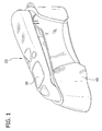
- FIG. 1 is a perspective view of a tympanic thermometer, in accordance with the principles of the present disclosure, mounted on a holder;
- FIG. 2 is a perspective view of the tympanic thermometer shown in FIG. 1 with a probe cover disposed on a distal end of the thermometer;
- FIG. 3 is a perspective view of the probe cover shown in FIG. 2 ;
- FIG. 4 is an exploded perspective view of the distal end of the tympanic thermometer shown in FIG. 2 ;
- FIG. 5 is a cross-sectional and fragmentary view of the probe cover mounted on the distal end of the tympanic thermometer taken through line 5-5 of FIG. 6 ;
- FIG. 6 is an end view of the distal end of the tympanic thermometer
- FIG. 7 is a cross-sectional and fragmentary view taken through line 7-7 of FIG. 6 showing the probe cover mounted on the distal end of the tympanic thermometer;
- FIG. 8 is a block diagram of an IR system of the tympanic thermometer
- FIG. 9 is an enlarged perspective view of the probe cover mounted on the distal end of the tympanic thermometer with portions broken away showing internal detail;
- FIG. 10 is an end view of a second embodiment of a distal end of a probe of the tympanic thermometer.
- FIG. 11 is a flow chart showing a control sequence performed by a processor of the tympanic thermometer.
- thermometers for measuring body temperature
- tympanic thermometer that includes a temperature sensor for measuring body temperature when the thermometer is inserted into an ear of a subject.
- the disclosed elements can be used with other types of electronic thermometers (ex., oral and rectal thermometer) without departing from the scope of the present invention.
- proximal will refer to the portion of a structure that is closer to a practitioner, while the term “distal” will refer to the portion that is farther from the practitioner.
- FIG. 2 illustrates “proximal” and “distal” for the structure, which is the fully assembled and usable tympanic thermometer.
- subject refers to a human patient or other animal having its body temperature measured.
- prtitioner refers to a doctor, nurse, parent or other care provider utilizing a tympanic thermometer to measure a subject's body temperature, and may include support personnel.
- tympanic thermometer 20 includes the necessary electronics and/or processing components to perform temperature measurement via the tympanic membrane, as is known to one skilled in the art. It is further envisioned that tympanic thermometer 20 may include a waveguide to facilitate sensing of the tympanic membrane heat energy. However, in the illustrated embodiments, the waveguide is beneficially omitted.
- the tympanic thermometer 20 is releasably mounted in a holder 40 for storage in contemplation for use.
- the tympanic thermometer 20 and holder 40 may be fabricated from semi-rigid, rigid plastic and/or metal materials suitable for temperature measurement and related use. It is envisioned that the holder 40 may include the electronics necessary to facilitate powering the tympanic thermometer 20, including, for example, battery charging capability, etc.
- the thermometer 20 is operable in a sleep mode wherein the thermometer 20 conserves energy and is not capable of performing a temperature measurement and an awake mode wherein the thermometer is operating at full power and is capable of performing a temperature measurement in certain conditions as will be described in greater detail below.
- tympanic thermometer 20 includes a cylindrical heat sensing probe, generally indicated at 22.
- the heat sensing probe 22 extends from a distal end 24 of tympanic thermometer 20 and defines a longitudinal axis X.
- the heat sensing probe 22 may have various geometric cross-sectional configurations, such as, for example, rectangular, elliptical, etc.
- a probe cover 32 may be disposed over the heat sensing probe 22.
- the probe cover 32 has a distal end 54 that is substantially enclosed by a film 56.
- the film is substantially transparent to infrared radiation and configured to facilitate sensing of infrared emissions by heat sensing probe 22.
- the film 56 is advantageously impervious to ear wax, moisture and bacteria to prevent disease propagation.
- the heat sensing probe 22 includes a nozzle, generally indicated at 100, mounted on a base 106.
- the nozzle 100 includes a base 110 and an elongated nose portion 112 projecting distally from the base.
- nozzle 100 may be fabricated from metal or other material which aides in the rapid exchange or transfer of heat.
- the nozzle 100 is formed of two parts (the base 110 and the nose portion 112) in the illustrated embodiment. It will be understood that a nozzle can be formed as one piece or more than two pieces without departing from the scope of the present invention. In particular, it is envisioned that the elongated nose section 112 can be formed of two or more pieces.
- the heat sensing probe 22 also includes a sensor can, generally indicated at 102, attached to temperature sensing electronics mounted on a distal end of a sensor housing 104 (or "retainer") received within the nozzle 100.
- the can 102 includes a sensor base 126 and a generally inverted cup-shaped tip 116 mounted on the base.
- a temperature sensor 122 e.g., a thermopile
- an infrared filter or window 120 and thermistor 124 are housed within can 102.
- the sensor housing 104 is mounted on the base 106 of probe 22 such that it extends generally coaxially within nozzle 100.
- the sensor housing 104 is fabricated from materials that provide for less thermo transmission (i.e., more insulated) than the nozzle 100, for example, plastic or other similar matter. So the material of the sensor housing 104 has a low thermal conductivity as compared to the thermal conductivity of the nozzle 100 and the base 126 of the can 102.
- the probe may also include a probe cover film 119 ( FIG. 8 ).
- the probe cover 32 is received on the nozzle 100 such that a distal portion of the cover is in thermal contact with the nose 112 of the nozzle.
- Probe cover 32 may be shaped, for example, frustoconically, or shaped in a tapered manner as to allow for easier insertion into the ear of the subject and attachment and detachment from the heat sensing probe 22.
- the probe cover 32 which is disposable, may be fabricated from materials suitable for measuring body temperature via the tympanic membrane with a tympanic thermometer measuring apparatus. These materials may include, for example, plastic materials, such as, for example, polypropylene, polyethylene, etc., depending on the particular temperature measurement application and/or preference of a practitioner.
- infrared energy IR ( FIG. 5 ) from the subject's tympanic membrane, for example, passes through the film 56 of probe cover 32 and enters can 102 through the window 120 of probe 22.
- This infrared energy may heat the can 102 and create a temperature gradient across the tip 116 from its distal end to its proximal end contacting the base 126. That is, the distal end can be much warmer than the proximal end.
- Heat from, for example, the ear of the subject is transferred from probe cover 32 to nozzle 100 to the base 126 of the can 102 via a path of heat flux (not shown).
- the path of heat flux heats the can 102 in order to reduce the temperature gradient across tip 116, thereby enabling a faster and more accurate temperature reading.
- An internal ridge 121 engages a distal side of a peripheral edge margin 114 of the base 126 to provide a heat conducting path from the nozzle 100 to the base 126 defining the path of heat flux. It is contemplated herein that nozzle 100 may be both in physical contact with the peripheral edge margin 114 or in a close proximate relationship with peripheral edge margin 114 of can 102. In either case, there should be such thermal contact as to enable heat transfer from the internal ridge 121 of the nozzle 100 to the peripheral edge margin 114 of the base 126.
- an IR signal emitter 130 and an IR signal detector 132 are disposed in a wall of the nozzle 100 at a proximal end of the nozzle.
- the IR signal emitter 130 is configured to emit an infrared signal and the IR signal detector 132 is configured to detect the infrared signal emitted by the IR signal emitter when the probe 22 is received in the probe cover 32.
- the IR emitter emits an infrared signal within about a 940nm wavelength range and the IR detector 132 generates a voltage level that is proportional to the strength of the infrared signal detected by the IR detector.
- a constant current source 131 provides electric current to the IR signal emitter 130.
- a signal conditioner 133 conditions the voltage signal produced by the IR signal detector 132 to condition the signal into a suitable form to be processed by a controller (not shown) of the thermometer 20.
- the constant current source 131, IR signal emitter 130, IR signal detector, and signal conditioner 133 comprise an IR system.
- An emitter fiber 134 extends within the wall of the nozzle 100 along a length of the nozzle from the IR emitter 130 at the proximal end of the nozzle to a distal end of the nozzle.
- the emitter fiber 134 comprises fiber optic strands for conducting an infrared signal.
- the emitter fiber 134 terminates at an emitter opening 136 in the distal end of the nozzle 100 so that the emitted infrared signal is conducted out of the distal end of the nozzle.
- a detector fiber 138 extends within the wall of the nozzle 100 along the length of the nozzle from the IR detector 132 at the proximal end of the nozzle to the distal end of the nozzle.
- the detector fiber 138 also comprises, for example, fiber optic strands for conducting an infrared signal.
- the detector fiber 138 terminates at a detector opening 140 in the distal end of the nozzle 100 so that the emitted infrared signal from the IR emitter 130 can be conducted to the IR detector 132 when the probe 22 is received in the probe cover 32.
- the film 56 of the probe cover 32 reflects the infrared signal emitted by the IR emitter 130 into the detector opening 140 and to the detector fiber 138 so that the infrared signal can be conducted to the IR detector 132.
- the infrared signal IRS is reflected multiple times between an inner surface of the film 56 and distal edge of the nozzle 100 until the signal reaches the detector opening 140. Once the signal is directed to the detector opening 140, the detector fiber 138 conducts the signal to the IR detector 132. The detection of the infrared signal by the IR detector 132 indicates that the probe 22 is received in the probe cover 32.
- the emitter opening 136 and detector opening 140 are spaced about 90 degrees from each other to ensure that the infrared signal reaches the IR detector 132 without having to travel an extended distance.
- the openings 136, 140 can be spaced at other distances and angles from each other without departing from the scope of the invention.
- FIG. 10 shows a second embodiment of a probe 222 of the present invention having several options for possible emitter and detector openings.
- the IR signal emitter 130 and IR signal detector 132 can be disposed at the distal end of the probe 22 near the emitter opening 136 and detector opening 140, respectively.
- the emitter fiber 134 and detector fiber 138 may be omitted.
- the temperature sensor 122, IR signal emitter 130, IR signal detector 132, constant current source 131, and signal conditioner 133 are operatively connected to a microprocessor system including a processor (not shown) of the controller.
- the processor is programmed to perform the temperature measurements for determining the temperature of the subject through the connection between the processor and the temperature sensor 122.
- the processor may also control the IR system for detecting the placement of the probe 22 as will be explained in greater detail below.
- the processor may control the IR system so that when the thermometer 20 is in the sleep mode, and when the thermometer is in the awake mode, but the probe 22 is not received in the probe cover 32, the processor will deactivate the IR system.
- the processor may also be programmed to prevent power from being supplied to the temperature sensor 122.
- the thermometer 20 would not be capable of performing a temperature measurement.
- the probe cover engages a switch (not shown) on the probe and switches the thermometer 20 to the awake mode so that the processor may activate the IR system.
- the microprocessor of the thermometer is described as controlling both the temperature measurements and the IR system, a separate processor from the thermometer microprocessor may control the IR system.
- the processor can be programmed to identify a first condition wherein the infrared signal detected by the IR detector 132 indicates that the probe 22 is received in the probe cover 32 but not inserted into the subject, and a second condition wherein the infrared signal detected by the IR detector indicates that the probe is received in the probe cover and inserted into the subject.
- the processor can be programmed to provide an indication, such as a read-out on a display 30 of the thermometer 20, notifying the practitioner which condition is being detected by the IR system.
- the indications can be provided in other ways such as audible indications without departing from the scope of the invention.
- the IR detector when the processor identifies the first condition, the IR detector produces a voltage based on the received infrared energy; this voltage will be the reference voltage.
- the IR detector detects a voltage level shift from the reference voltage established during the first condition.
- the voltage ranges corresponding to the first and second conditions can have other values without departing from the scope of the invention.
- the processor can also be programmed to activate the temperature sensor 122 to measure the temperature of the subject only after the processor identifies the second condition wherein the probe 22 is received in the probe cover 32 and inserted into the subject. This improves the accuracy of the thermometer 20 because power is not supplied to the temperature sensor 122 until the probe 22 is properly inserted into the subject. Also, external effects on the temperature sensor 122 are minimized making the temperature readings produced by the temperature sensor more accurate. Once the thermometer 20 acquires the subject's temperature, the processor may deactivate the IR system to conserve battery life and prevent the reuse of the probe cover.
Applications Claiming Priority (1)
| Application Number | Priority Date | Filing Date | Title |
|---|---|---|---|
| US13/249,636 US8292500B1 (en) | 2011-09-30 | 2011-09-30 | IR sensor for electronic thermometer |
Publications (1)
| Publication Number | Publication Date |
|---|---|
| EP2574888A1 true EP2574888A1 (fr) | 2013-04-03 |
Family
ID=46940308
Family Applications (1)
| Application Number | Title | Priority Date | Filing Date |
|---|---|---|---|
| EP12183796A Withdrawn EP2574888A1 (fr) | 2011-09-30 | 2012-09-11 | Capteur IR pour thermomètre électronique |
Country Status (2)
| Country | Link |
|---|---|
| US (2) | US8292500B1 (fr) |
| EP (1) | EP2574888A1 (fr) |
Citations (2)
| Publication number | Priority date | Publication date | Assignee | Title |
|---|---|---|---|---|
| US20100208767A1 (en) * | 2009-02-17 | 2010-08-19 | Erik Chen | Ear Thermometer using optical fiber transmission |
| US20110134962A1 (en) * | 2008-12-29 | 2011-06-09 | Jacob Fraden | Probe cover with matching feature for a medical thermometer |
Family Cites Families (30)
| Publication number | Priority date | Publication date | Assignee | Title |
|---|---|---|---|---|
| US3905232A (en) | 1973-10-05 | 1975-09-16 | Ivac Corp | Electronic thermometer |
| US4341992A (en) | 1980-01-21 | 1982-07-27 | Control Electronics Co., Inc. | Conductive probe cover |
| US4900162A (en) * | 1989-03-20 | 1990-02-13 | Ivac Corporation | Infrared thermometry system and method |
| US5066142A (en) | 1990-03-08 | 1991-11-19 | Ivac Corporation | Protective apparatus for a biomedical probe |
| US5167235A (en) | 1991-03-04 | 1992-12-01 | Pat O. Daily Revocable Trust | Fiber optic ear thermometer |
| US5487607A (en) | 1992-04-08 | 1996-01-30 | Omron Corporation | Radiation clinical thermometer |
| US5411032A (en) | 1993-06-18 | 1995-05-02 | Infra-Temp Inc. | Electronic thermometer probe cover |
| DE19543096C2 (de) | 1995-11-18 | 1998-07-23 | Braun Ag | Infrarot-Strahlungsthermometer |
| EP0861425A1 (fr) | 1995-11-18 | 1998-09-02 | Braun Aktiengesellschaft | Procede d'evaluation du signal emis par un thermometre a infrarouge et thermometre a infrarouge approprie |
| DE19600334C2 (de) | 1996-01-08 | 2002-11-14 | Braun Gmbh | Verfahren zur Auswertung des von einem Infrarotsensor eines Infrarot-Thermometers gelieferten Meßsignals sowie Infrarot-Thermometer |
| AU7807898A (en) | 1997-06-03 | 1998-12-21 | Trutek, Inc. | Tympanic thermometer with modular sensing probe |
| ATE248356T1 (de) | 1998-01-30 | 2003-09-15 | Tecnimed Srl | Infrarot thermometer |
| WO1999056629A1 (fr) * | 1998-05-06 | 1999-11-11 | Matsushita Electric Industrial Co., Ltd. | Thermometre auriculaire a usage feminin |
| JP2000131146A (ja) | 1998-10-28 | 2000-05-12 | Omron Corp | 電子温度計 |
| JP2000217788A (ja) | 1999-02-01 | 2000-08-08 | Matsushita Electric Ind Co Ltd | 放射体温計 |
| DE19913672A1 (de) | 1999-03-25 | 2000-11-02 | Braun Gmbh | Infrarot-Thermometer mit einer beheizbaren Meßspitze und Schutzkappe |
| WO2001096825A1 (fr) | 2000-06-13 | 2001-12-20 | Omron Corporation | Pyrometre |
| JP3945189B2 (ja) | 2001-06-01 | 2007-07-18 | オムロンヘルスケア株式会社 | 赤外線体温計 |
| US8328420B2 (en) * | 2003-04-22 | 2012-12-11 | Marcio Marc Abreu | Apparatus and method for measuring biologic parameters |
| US20060078037A1 (en) * | 2003-04-16 | 2006-04-13 | Tzong-Sheng Lee | Thermometer with image display |
| EP1642084A1 (fr) * | 2003-07-03 | 2006-04-05 | Optris GmbH | Systeme de visee et appareil comportant un dispositif de mesure, de travail et/ou d'actionnement pouvant etre utilise avec ou sans contact |
| US7355178B2 (en) * | 2004-06-22 | 2008-04-08 | Everest Charles E | Infrared thermometer with through-the-lens visible targeting system |
| US7572056B2 (en) | 2004-11-16 | 2009-08-11 | Welch Allyn, Inc. | Probe cover for thermometry apparatus |
| US7815367B2 (en) * | 2004-11-16 | 2010-10-19 | Welch Allyn, Inc. | Multi-site infrared thermometer |
| US7536568B2 (en) | 2005-12-01 | 2009-05-19 | Covidien Ag | Ultra low power wake-up circuit |
| US7314310B2 (en) | 2006-04-13 | 2008-01-01 | The General Electric Company | Predictive temperature probe with proximity sensor |
| JP5053674B2 (ja) | 2007-03-26 | 2012-10-17 | テルモ株式会社 | 耳式体温計 |
| US7813889B2 (en) | 2008-01-16 | 2010-10-12 | Welch Allyn, Inc. | Guiding IR temperature measuring device with probe cover |
| US8136985B2 (en) * | 2009-05-05 | 2012-03-20 | Welch Allyn, Inc. | IR thermometer thermal isolation tip assembly |
| MX2012011692A (es) * | 2010-04-05 | 2013-04-03 | Kaz Europe Sa | Detector de insercion para una sonda medica. |
-
2011
- 2011-09-30 US US13/249,636 patent/US8292500B1/en active Active
-
2012
- 2012-09-11 EP EP12183796A patent/EP2574888A1/fr not_active Withdrawn
- 2012-10-16 US US13/613,842 patent/US8622613B2/en active Active
Patent Citations (2)
| Publication number | Priority date | Publication date | Assignee | Title |
|---|---|---|---|---|
| US20110134962A1 (en) * | 2008-12-29 | 2011-06-09 | Jacob Fraden | Probe cover with matching feature for a medical thermometer |
| US20100208767A1 (en) * | 2009-02-17 | 2010-08-19 | Erik Chen | Ear Thermometer using optical fiber transmission |
Also Published As
| Publication number | Publication date |
|---|---|
| US20130083822A1 (en) | 2013-04-04 |
| US8292500B1 (en) | 2012-10-23 |
| US8622613B2 (en) | 2014-01-07 |
Similar Documents
| Publication | Publication Date | Title |
|---|---|---|
| US20130083823A1 (en) | Electronic thermometer with image sensor and display | |
| EP1581785B1 (fr) | Capuchon de sonde de thermometre tympanique | |
| CA2509033C (fr) | Extremite thermique de thermometre tympanique | |
| US8949065B2 (en) | Capacitive sensor for thermometer probe | |
| US20060120432A1 (en) | Tympanic thermometer with ejection mechanism | |
| US8622613B2 (en) | IR sensor for electronic thermometer | |
| AU2003303687B2 (en) | Tympanic thermometer with ejection mechanism | |
| US20080042075A1 (en) | Thermometry apparatus probe sterilization | |
| AU2007200873B2 (en) | Thermal tympanic thermometer tip | |
| RU2319119C2 (ru) | Колпачок датчика | |
| NZ540637A (en) | Tympanic thermometer with ejection mechanism |
Legal Events
| Date | Code | Title | Description |
|---|---|---|---|
| PUAI | Public reference made under article 153(3) epc to a published international application that has entered the european phase |
Free format text: ORIGINAL CODE: 0009012 |
|
| 17P | Request for examination filed |
Effective date: 20120911 |
|
| AK | Designated contracting states |
Kind code of ref document: A1 Designated state(s): AL AT BE BG CH CY CZ DE DK EE ES FI FR GB GR HR HU IE IS IT LI LT LU LV MC MK MT NL NO PL PT RO RS SE SI SK SM TR |
|
| AX | Request for extension of the european patent |
Extension state: BA ME |
|
| REG | Reference to a national code |
Ref country code: HK Ref legal event code: DE Ref document number: 1183937 Country of ref document: HK |
|
| RAP1 | Party data changed (applicant data changed or rights of an application transferred) |
Owner name: KPR U.S., LLC |
|
| 17Q | First examination report despatched |
Effective date: 20181029 |
|
| STAA | Information on the status of an ep patent application or granted ep patent |
Free format text: STATUS: THE APPLICATION IS DEEMED TO BE WITHDRAWN |
|
| 18D | Application deemed to be withdrawn |
Effective date: 20190509 |
|
| REG | Reference to a national code |
Ref country code: HK Ref legal event code: WD Ref document number: 1183937 Country of ref document: HK |