EP2574846A2 - A method of operating a combustion chamber - Google Patents
A method of operating a combustion chamber Download PDFInfo
- Publication number
- EP2574846A2 EP2574846A2 EP12184230A EP12184230A EP2574846A2 EP 2574846 A2 EP2574846 A2 EP 2574846A2 EP 12184230 A EP12184230 A EP 12184230A EP 12184230 A EP12184230 A EP 12184230A EP 2574846 A2 EP2574846 A2 EP 2574846A2
- Authority
- EP
- European Patent Office
- Prior art keywords
- air
- wall
- mixing
- supplying
- combustion chamber
- Prior art date
- Legal status (The legal status is an assumption and is not a legal conclusion. Google has not performed a legal analysis and makes no representation as to the accuracy of the status listed.)
- Withdrawn
Links
- 238000002485 combustion reaction Methods 0.000 title claims abstract description 125
- 238000000034 method Methods 0.000 title claims abstract description 41
- 238000001816 cooling Methods 0.000 claims abstract description 110
- 238000011144 upstream manufacturing Methods 0.000 claims abstract description 54
- 239000000446 fuel Substances 0.000 claims description 13
- 239000002826 coolant Substances 0.000 description 11
- 239000000203 mixture Substances 0.000 description 2
- 230000009286 beneficial effect Effects 0.000 description 1
Images

Classifications
-
- F—MECHANICAL ENGINEERING; LIGHTING; HEATING; WEAPONS; BLASTING
- F23—COMBUSTION APPARATUS; COMBUSTION PROCESSES
- F23R—GENERATING COMBUSTION PRODUCTS OF HIGH PRESSURE OR HIGH VELOCITY, e.g. GAS-TURBINE COMBUSTION CHAMBERS
- F23R3/00—Continuous combustion chambers using liquid or gaseous fuel
- F23R3/02—Continuous combustion chambers using liquid or gaseous fuel characterised by the air-flow or gas-flow configuration
- F23R3/04—Air inlet arrangements
-
- F—MECHANICAL ENGINEERING; LIGHTING; HEATING; WEAPONS; BLASTING
- F23—COMBUSTION APPARATUS; COMBUSTION PROCESSES
- F23R—GENERATING COMBUSTION PRODUCTS OF HIGH PRESSURE OR HIGH VELOCITY, e.g. GAS-TURBINE COMBUSTION CHAMBERS
- F23R3/00—Continuous combustion chambers using liquid or gaseous fuel
- F23R3/02—Continuous combustion chambers using liquid or gaseous fuel characterised by the air-flow or gas-flow configuration
- F23R3/04—Air inlet arrangements
- F23R3/06—Arrangement of apertures along the flame tube
-
- F—MECHANICAL ENGINEERING; LIGHTING; HEATING; WEAPONS; BLASTING
- F23—COMBUSTION APPARATUS; COMBUSTION PROCESSES
- F23R—GENERATING COMBUSTION PRODUCTS OF HIGH PRESSURE OR HIGH VELOCITY, e.g. GAS-TURBINE COMBUSTION CHAMBERS
- F23R3/00—Continuous combustion chambers using liquid or gaseous fuel
- F23R3/42—Continuous combustion chambers using liquid or gaseous fuel characterised by the arrangement or form of the flame tubes or combustion chambers
- F23R3/50—Combustion chambers comprising an annular flame tube within an annular casing
Definitions
- the present invention relates to a method of operating a combustion chamber and in particular to a method of operating a gas turbine engine combustion chamber.
- combustion chambers use a "rich-burn" design.
- the fuel injectors supply a mixture of air and fuel at a ratio that is much richer than the stoichiometric value of approximately 15.
- the rich mixture of air and fuel is then diluted with air supplied through rows of mixing ports in the walls of the combustion chamber.
- the walls of combustion chambers have been provided with one, two or three rows of mixing ports. The total flow of air to the combustion chamber is divided and a first portion is supplied to the fuel injector, a second portion is supplied to the mixing ports and a third portion is supplied to cool the walls of the combustion chamber.
- the present invention seeks to provide a novel method of operating a combustion chamber which reduces, preferably overcomes, the above mentioned problem.
- the present invention provides a method of operating a combustion chamber, the combustion chamber comprising an upstream wall having at least one inlet for a fuel injector and primary air, at least one double skin annular wall, the at least one double skin annular wall comprising an inner wall and an outer wall, the at least one double skin annular wall having at least one mixing port extending there-through, the inner wall or the outer wall having at least one additional mixing port extending there-through adjacent the mixing port, the method comprising supplying air for the combustion chamber, the method comprising supplying 10% of the air for the combustion chamber through the inlet in the upstream wall, supplying 64% to 80% of the air for mixing, and supplying 10% to 26% of the air for cooling the at least one double skin annular wall and the upstream wall, the method further comprising supplying a first portion of the 64% to 80% of the air for mixing through the at least one mixing port into the combustion chamber and supplying a second portion of the 64% to 80% of the air for mixing to provide convective cooling of the at least one
- the method may comprise supplying half of the air for mixing through the at least one mixing port into the combustion chamber and supplying half of the air for mixing to provide convective cooling of the at least one double skin annular wall before being supplied through the at least one additional mixing port into the combustion chamber.
- the at least one mixing port extending through the at least one double skin annular wall comprising at least one primary mixing port extending through the at least one double skin annular wall and at least one secondary mixing port extending through the at least one double skin annular wall and arranged downstream of the at least one primary mixing port, the at least one additional mixing port in the inner wall or outer wall comprising at least one additional primary mixing port extending through the inner wall or the outer wall adjacent the primary mixing port and at least one additional secondary mixing port extending through the inner wall or the outer wall adjacent the secondary mixing port, the method comprising supplying 10% of the air for the combustion chamber through the inlet in the upstream wall, supplying 32% to 40% of the air for primary mixing, supplying 32% to 40% of the air for secondary mixing and supplying 10% to 26% of the air for cooling the at least one double skin annular wall and the upstream wall, the method further comprising supplying a first portion of the 32% to 40% of the air for primary mixing through the at least one primary mixing port into the combustion chamber and supplying a second portion of the 32%
- the method may comprise supplying 10% of the air for the combustion chamber through the inlet in the upstream wall, supplying 35% to 40% of the air for primary mixing, supplying 35% to 40% of the air for secondary mixing and supplying 10% to 20% of the air for cooling the at least one double skin annular wall and the upstream wall, the method further comprising supplying a first portion of the 35% to 40% of the air for primary mixing through the at least one primary mixing port into the combustion chamber and supplying a second portion of the 35% to 40% of the air for primary mixing to provide convective cooling of the at least one double skin annular wall before being supplied through the at least one additional primary mixing port into the combustion chamber, supplying a first portion of the 35% to 40% of the air for secondary mixing through the at least one secondary mixing port into the combustion chamber and supplying a second portion of the 35% to 40% of the air for secondary mixing to provide convective cooling of the at least one double skin annular wall before being supplied through the at least one additional secondary mixing port into the combustion chamber and supplying the 10% to 20% of the
- the method may comprise supplying 10% of the air for the combustion chamber through the inlet in the upstream wall, supplying 40% of the air for primary mixing, supplying 40% of the air for secondary mixing and supplying 10% of the air for cooling the at least one double skin annular wall and the upstream wall, the method further comprising supplying a first portion of the 40% of the air for primary mixing through the at least one primary mixing port into the combustion chamber and supplying a second portion of the 40% of the air for primary mixing to provide convective cooling of the at least one double skin annular wall before being supplied through the at least one additional primary mixing port into the combustion chamber, supplying a first portion of the 40% of the air for secondary mixing through the at least one secondary mixing port into the combustion chamber and supplying a second portion of the 40% of the air for secondary mixing to provide convective cooling of the at least one double skin annular wall before being supplied through the at least one additional secondary mixing port into the combustion chamber and supplying the 10% of the air for cooling the at least one double skin annular wall and the upstream wall to provide convec
- the method may comprise supplying half of the air for primary mixing through the at least one primary mixing port into the combustion chamber and supplying half of the air for primary mixing to provide convective cooling of the at least one double skin annular wall before being supplied through the at least one additional primary mixing port into the combustion chamber.
- the method may comprise supplying half of the air for secondary mixing through the at least one secondary mixing port into the combustion chamber and supplying half of the air for secondary mixing to provide convective cooling of the at least one double skin annular wall before being supplied through the at least one additional secondary mixing port into the combustion chamber.
- the at least one double skinned annular wall may comprise a plurality of circumferentially spaced additional primary mixing ports and a plurality of circumferentially spaced additional secondary mixing ports.
- the at least one additional secondary mixing port may be arranged around the at least one secondary mixing port.
- the radially inner annular wall 44 has a plurality of circumferentially spaced mixing ports 58 through which a flow of mixing air is arranged to flow into the annular combustion chamber 42 in operation.
- the radially outer annular wall 46 has a plurality of circumferentially spaced mixing ports 62 through which a flow of mixing air is arranged to flow into the annular combustion chamber 42 in operation.
- the fuel injector apertures 52 in the upstream wall 48 define inlets for primary air for the annular combustion chamber 42.
- the radially inner annular wall 44 is a double skin annular wall and the radially outer annular wall 46 is a double skin annular wall.
- the radially inner annular wall 44 comprises a radially inner wall 66 and a radially outer wall 68 and the radially outer annular wall 46 comprises a radially inner wall 70 and a radially outer wall 72.
- the radially outer wall 68 of the radially inner annular wall 44 comprises a plurality of tiles 68A and 68B and the radially inner wall 70 of the radially outer annular wall 46 comprises a plurality of tiles 70A and 70B.
- the double skin radially inner annular wall 44 has a plurality of circumferentially spaced primary mixing ports 58A extending there-through and a plurality of circumferentially spaced secondary mixing ports 58B extending there-through and the secondary mixing ports 58B are arranged downstream of the primary mixing ports 58A.
- the double skin radially outer annular wall 46 has a plurality of circumferentially spaced primary mixing ports 62A extending there-through and a plurality of circumferentially spaced secondary mixing ports 62B extending there-through and the secondary mixing ports 62B are arranged downstream of the primary mixing ports 62A.
- the radially outer wall 68 of the double skin radially inner wall 44 has a plurality of circumferentially spaced additional primary mixing ports 74A extending there-through adjacent the primary mixing ports 58A, the radially outer wall 68 of the double skin radially inner wall 44 also has a plurality of circumferentially spaced additional secondary mixing ports 74B extending there-through adjacent the secondary mixing ports 58B.
- the radially inner wall 70 of the double skin radially outer wall 46 has a plurality of circumferentially spaced additional primary mixing ports 76A extending there-through adjacent the primary mixing ports 62A
- the radially inner wall 70 of the double skin radially outer wall 46 also has a plurality of circumferentially spaced additional secondary mixing ports 76B extending there-through adjacent the secondary mixing ports 62B.
- Each of the additional primary mixing ports 74A is arranged around the respective primary mixing port 58A and each of the additional secondary mixing ports 74B is arranged around the respective secondary mixing port 58B.
- each of the additional primary mixing ports 76A is arranged around the respective primary mixing port 62A and each of the additional secondary mixing ports 76B is arranged around the respective secondary mixing port 62B.
- the radially inner wall 66 of the double skin radially inner annular wall 44 also has a plurality of smaller diameter cooling apertures 60 through which a flow of coolant, air, is arranged to flow in operation.
- the coolant, air is arranged to flow through the apertures 60 into chambers 80 defined between the radially inner wall 66 and the tiles 68A and 68B of the radially outer wall 68 of the double skin radially inner wall 44.
- the coolant is arranged to impinge upon the radially inner surfaces 82 of the tiles 68A and 68B to provide impingement cooling and then to flow over the radially inner surfaces 82 of the tiles 68A and 68B to provide convective cooling of the tiles 68A and 68B.
- the radially outer wall 72 of the double skin radially outer annular wall 46 also has a plurality of smaller diameter cooling apertures 64 through which a flow of coolant, air, is arranged to flow in operation.
- the coolant, air is arranged to flow through the apertures 64 into chambers 88 defined between the radially outer wall 72 and the tiles 70A and 70B of the radially inner wall 70 of the double skin radially outer wall 46.
- the coolant is arranged to impinge upon the radially outer surfaces 90 of the tiles 70A and 70B to provide impingement cooling and then to flow over the radially outer surfaces 90 of the tiles 70A and 70B to provide convective cooling of the tiles 70A and 70B.
- the tiles 70A and 70B of the radially inner wall 70 of the double skin radially outer annular wall 46 have a plurality of effusion cooling apertures 86 through which a flow of coolant, air, is arranged to flow in operation from the chambers 88 and over the radially inner surfaces 92 of the tiles 70A and 70B. Some of the coolant in the chambers 88 is arranged to flow through the additional primary mixing ports 76A and the additional secondary mixing ports 76B.
- 10% of the air for the combustion chamber 42 is supplied through the inlets, the fuel injector apertures 52, in the upstream wall 48, 32% to 40% of the air is supplied for primary mixing, 32% to 40% of the air is supplied for secondary mixing and 10% to 26% of the air is supplied for cooling the double skin radially inner annular wall 44 and the double skin radially outer annular wall 46 and the upstream wall 48.
- a first portion A of the 32% to 40% of the air for primary mixing is supplied through the primary mixing ports 58A and 62A in the double skin radially inner annular wall 44 and the double skin radially outer annular wall 46 respectively into the combustion chamber 42.
- a second portion B of the 32% to 40% of the air for primary mixing provides convective cooling of the double skin radially inner annular wall 44 and the double skin radially outer annular wall 46 before it is supplied through the additional primary mixing ports 74A and 76A in the radially outer wall 68 of the double skin radially inner annular wall 44 and in the radially inner wall 70 of the double skin radially outer annular wall 46 respectively into the combustion chamber 42.
- a first portion C of the 32% to 40% of the air for secondary mixing is supplied through the secondary mixing ports 58B and 62B in the double skin radially inner annular wall 44 and the double skin radially outer annular wall 46 respectively into the combustion chamber 42.
- a second portion D of the 32% to 40% of the air for secondary mixing provides convective cooling of the double skin radially inner annular wall 44 and the double skin radially outer annular wall 46 before it is supplied through the additional secondary mixing ports 74B and 76B in the radially outer wall 68 of the double skin radially inner annular wall 44 and in the radially inner wall 70 of the double skin radially outer annular wall 46 respectively into the combustion chamber 42.
- 35% to 40% of the air is supplied for primary mixing
- 35% to 40% of the air is supplied for secondary mixing
- 10% to 20% of the air is supplied for cooling the double skin radially inner annular wall 44 and the double skin radially outer annular wall 46 and the upstream wall 48.
- a first portion A of the 35% to 40% of the air for primary mixing is supplied through the primary mixing ports 58A and 62A in the double skin radially inner annular wall 44 and the double skin radially outer annular wall 46 respectively into the combustion chamber 42.
- a second portion B of the 35% to 40% of the air for primary mixing provides convective cooling of the double skin radially inner annular wall 44 and the double skin radially outer annular wall 46 before it is supplied through the additional primary mixing ports 74A and 76A in the radially outer wall 68 of the double skin radially inner annular wall 44 and in the radially inner wall 70 of the double skin radially outer annular wall 46 respectively into the combustion chamber 42.
- a first portion C of the 35% to 40% of the air for secondary mixing is supplied through the secondary mixing ports 58B and 62B in the double skin radially inner annular wall 44 and the double skin radially outer annular wall 46 respectively into the combustion chamber 42.
- a second portion D of the 35% to 40% of the air for secondary mixing provides convective cooling of the double skin radially inner annular wall 44 and the double skin radially outer annular wall 46 before it is supplied through the additional secondary mixing ports 74B and 76B in the radially outer wall 68 of the double skin radially inner annular wall 44 and in the radially inner wall 70 of the double skin radially outer annular wall 46 respectively into the combustion chamber 42.
- 10% to 20% of the air is used for cooling the double skin radially inner annular wall 44 and the double skin radially outer annular wall 46 and the upstream wall 48 provides convective cooling and/or effusion cooling of the double skin radially inner annular wall 44, the double skin radially outer annular wall 46 and the upstream wall 48.
- 40% of the air is supplied for primary mixing, 40% of the air is supplied for secondary mixing and 10% of the air is supplied for cooling the double skin radially inner annular wall 44 and the double skin radially outer annular wall 46 and the upstream wall 48.
- a first portion A of the 40% of the air for primary mixing is supplied through the primary mixing ports 58A and 62A in the double skin radially inner annular wall 44 and the double skin radially outer annular wall 46 respectively into the combustion chamber 42.
- a second portion B of the 40% of the air for primary mixing provides convective cooling of the double skin radially inner annular wall 44 and the double skin radially outer annular wall 46 before it is supplied through the additional primary mixing ports 74A and 76A in the radially outer wall 68 of the double skin radially inner annular wall 44 and in the radially inner wall 70 of the double skin radially outer annular wall 46 respectively into the combustion chamber 42.
- a first portion C of the 40% of the air for secondary mixing is supplied through the secondary mixing ports 58B and 62B in the double skin radially inner annular wall 44 and the double skin radially outer annular wall 46 respectively into the combustion chamber 42.
- half of the air for mixing is supplied through the mixing ports 58A, 58B, 62A and 62B into the combustion chamber 42 and half of the air for mixing is used to provide impingement and/or convective cooling of the double skin radially inner annular wall 44 and the double skin radially outer annular wall 46 before being supplied through the additional mixing ports 74A, 74B, 76A and 76B into the combustion chamber 42.
- half of the air for primary mixing A is supplied through the primary mixing ports 58A and 62A into the combustion chamber 42 and half of the air for primary mixing B is used to provide impingement and/or convective cooling of the double skin radially inner annular wall 42 and the double skin radially outer annular wall 46 before being supplied through the additional primary mixing ports 74A and 76A into the combustion chamber 42 and half of the air for secondary mixing C is supplied through the secondary mixing ports 58B and 62B into the combustion chamber 42 and half of the air for secondary mixing D is used to provide impingement and/or convective cooling of the double skin radially inner annular wall 44 and the double skin radially outer annular wall 46 before being supplied through the additional secondary mixing ports 74B and 76B into the combustion chamber 42.
- FIG. 3 shows an embodiment of the double skin radially outer annular wall 46 and shows a tile 70A of the radially inner wall 70 and the radially outer wall 72.
- the radially outer wall 72 has apertures 64 to provide impingement cooling of the radially outer surface 90 of the tiles 70A, alternatively the radially outer surface 90 of the tiles 70A may be convectively cooled or the radially outer surface 90 of the tiles 70A may be provided with radially outwardly extending ribs, or projections, to provide cooling of the tiles 70A.
- Each mixing port 62A is defined by a boss 94 which is integral, e.g. cast integral, with the tile 70A and abuts the radially inner surface of the radially outer wall 72.
- Each additional mixing port 76A, or 76B comprises one or more slots in the tile 70A which are arranged around, e.g. concentrically around, the boss 94.
- Figure 4 shows another embodiment of the double skin radially outer annular wall 46 and shows a tile 70A of the radially inner wall 70 and the radially outer wall 72.
- the radially outer wall 72 has apertures 64 to provide impingement cooling of the radially outer surface 90 of the tiles 70A, alternatively the radially outer surface 90 of the tiles 70A may be convectively cooled or the radially outer surface 90 of the tiles 70A may be provided with radially outwardly extending ribs, or projections, to provide cooling of the tiles 70A.
- the tiles 70A also have effusion cooling apertures 86 at predetermined locations to cool hot spots on the tiles 70A.
- Each mixing port 62A is defined by a boss 96 which extends radially through the radially outer wall 72 and a tile 70A of the radially inner wall 70 and the boss 96 has a flange 98 which abuts, and is secured to, the radially outer surface of the radially outer wall 72.
- Each additional mixing port 76A, or 76B comprises an annular slot defined between the tile 70A and the boss 96.
- Each additional mixing port 76A or 76B is concentric with the boss 96.
- Figure 5 shows a further embodiment of the double skin radially outer annular wall 46 and shows a tile 70A of the radially inner wall 70 and the radially outer wall 72.
- the radially outer wall 72 has apertures 64 to provide impingement cooling of the radially outer surface 90 of the tiles 70A, alternatively the radially outer surface 90 of the tiles 70A may be convectively cooled or the radially outer surface 90 of the tiles 70A may be provided with radially outwardly extending ribs, or projections, to provide cooling of the tiles 70A.
- Each mixing port 62A is defined by a boss 100 which extends radially through the tile 70A of the radially inner wall 70 and the boss 100 has a flange 102 which abuts, and is secured to, the radially inner surface of the radially outer wall 72.
- Each additional mixing port 76A, or 76B comprises an annular slot defined between the tile 70A and the boss 100.
- Each additional mixing port 76A or 76B is concentric with the boss 100.
- Each boss 100 has a portion 104 which extends radially into the combustion chamber 42 and enhances mixing in the combustion chamber 42. The portion 104 is chamfered such that the downstream end 106 extends radially further into the combustion chamber 42 than the upstream end 108.
- the additional mixing air flowing through the additional mixing port 76A, 76B also cools the portion of the boss 100 extending into the combustion chamber 42.
- the present invention provides more air than is currently supplied for mixing purposes.
- the present invention uses some, or all, of the air currently used to provide film cooling of the inner wall of the double skinned annular wall(s) to provide convection cooling and/or effusion cooling of the double skinned annular wall(s) and this air is then supplied through the additional mixing port in the inner wall of the double skinned annular wall(s) to function as mixing air to provide supplementary mixing air.
- the present invention provides these additional mixing ports adjacent to, around, the mixing ports.
- the additional mixing ports may be concentric annular slots around the mixing ports or as a plurality of slots arranged concentrically with the mixing ports.
- the present invention uses some of the air currently supplied through the mixing ports and used as mixing air to provide convection cooling and/or effusion cooling of the double skinned annular wall(s) and this air is then supplied through the additional mixing port in the inner wall of the double skinned annular wall(s) to function as mixing air to provide supplementary mixing air.
- the advantage of the present invention is that it increases the amount of air available for mixing in a "rich burn" combustion chamber and therefore improves the mixing process within the combustion chamber and hence reduces engine emissions.
- the present invention significantly increases the amount of air available for cooling of the double skinned annular wall(s) compared to current designs.
- the increased mass flow of air for cooling of the double skinned annular wall(s) reduces the level of temperature rise in the cooling air, so improving the cooling performance and at the same time any temperature rise that does occur in the cooling air is beneficial in improving the mixing performance in the combustion chamber, because this spent cooling air is supplied through the additional mixing port(s).
- the supply of mixing air through the double skinned annular wall(s) results in a pressure drop in the cooling air and hence in the cooling air supplied through the additional mixing port(s) as mixing air.
- This pressure drop reduces the ability of the cooling air flowing through the additional mixing port(s) to mix efficiently with the combustion products in the combustion chamber. That is why the present invention does not supply all the air required for mixing through the double skinned annular wall(s) to cool the double skinned annular wall(s) before being used as mixing air.
- An optimum use of the air is to supply half of the air directly through the mixing port(s) as mixing air and to supply half of the air for cooling the double skinned annular wall(s) and then through the additional mixing port(s) as mixing air so as to provide sufficient momentum to achieve efficient mixing of the mixing air and combustion products in the combustion chamber.
Landscapes
- Engineering & Computer Science (AREA)
- Chemical & Material Sciences (AREA)
- Combustion & Propulsion (AREA)
- Mechanical Engineering (AREA)
- General Engineering & Computer Science (AREA)
- Combustion Methods Of Internal-Combustion Engines (AREA)
Abstract
Description
- The present invention relates to a method of operating a combustion chamber and in particular to a method of operating a gas turbine engine combustion chamber.
- Most gas turbine engine combustion chambers use a "rich-burn" design. In these "rich-burn" design combustion chambers the fuel injectors supply a mixture of air and fuel at a ratio that is much richer than the stoichiometric value of approximately 15. To meet emission requirements and engine operating requirements, the rich mixture of air and fuel is then diluted with air supplied through rows of mixing ports in the walls of the combustion chamber. The walls of combustion chambers have been provided with one, two or three rows of mixing ports. The total flow of air to the combustion chamber is divided and a first portion is supplied to the fuel injector, a second portion is supplied to the mixing ports and a third portion is supplied to cool the walls of the combustion chamber.
- A problem with the "rich-burn" design is that as the gas turbine engine operating cycle has become more arduous, additional air is required to cool the walls of the combustion chamber and additional air is required to be supplied to the fuel injectors. Thus, "rich burn" combustion chambers have an insufficient amount of air for the mixing ports once the requirements of the fuel injectors and the wall cooling have been fulfilled. This results in a reduction in the amount of air available for the mixing ports, which therefore reduces the ability to reduce, or minimise, the emissions from the combustion chamber.
- Accordingly the present invention seeks to provide a novel method of operating a combustion chamber which reduces, preferably overcomes, the above mentioned problem.
- Accordingly the present invention provides a method of operating a combustion chamber, the combustion chamber comprising an upstream wall having at least one inlet for a fuel injector and primary air, at least one double skin annular wall, the at least one double skin annular wall comprising an inner wall and an outer wall, the at least one double skin annular wall having at least one mixing port extending there-through, the inner wall or the outer wall having at least one additional mixing port extending there-through adjacent the mixing port,
the method comprising supplying air for the combustion chamber,
the method comprising supplying 10% of the air for the combustion chamber through the inlet in the upstream wall, supplying 64% to 80% of the air for mixing, and supplying 10% to 26% of the air for cooling the at least one double skin annular wall and the upstream wall,
the method further comprising supplying a first portion of the 64% to 80% of the air for mixing through the at least one mixing port into the combustion chamber and supplying a second portion of the 64% to 80% of the air for mixing to provide convective cooling of the at least one double skin annular wall before being supplied through the additional mixing port into the combustion chamber and supplying the 10% to 26% of the air for cooling the at least one double skin annular wall and the upstream wall to provide convective cooling and/or effusion cooling of the at least one double skin annular wall and the upstream wall. - The method may comprise supplying half of the air for mixing through the at least one mixing port into the combustion chamber and supplying half of the air for mixing to provide convective cooling of the at least one double skin annular wall before being supplied through the at least one additional mixing port into the combustion chamber.
- The at least one mixing port extending through the at least one double skin annular wall comprising at least one primary mixing port extending through the at least one double skin annular wall and at least one secondary mixing port extending through the at least one double skin annular wall and arranged downstream of the at least one primary mixing port, the at least one additional mixing port in the inner wall or outer wall comprising at least one additional primary mixing port extending through the inner wall or the outer wall adjacent the primary mixing port and at least one additional secondary mixing port extending through the inner wall or the outer wall adjacent the secondary mixing port,
the method comprising supplying 10% of the air for the combustion chamber through the inlet in the upstream wall, supplying 32% to 40% of the air for primary mixing, supplying 32% to 40% of the air for secondary mixing and supplying 10% to 26% of the air for cooling the at least one double skin annular wall and the upstream wall,
the method further comprising supplying a first portion of the 32% to 40% of the air for primary mixing through the at least one primary mixing port into the combustion chamber and supplying a second portion of the 32% to 40% of the air for primary mixing to provide convective cooling of the at least one double skin annular wall before being supplied through the at least one additional primary mixing port into the combustion chamber, supplying a first portion of the 32% to 40% of the air for secondary mixing through the at least one secondary mixing port into the combustion chamber and supplying a second portion of the 32% to 40% of the air for secondary mixing to provide convective cooling of the at least one double skin annular wall before being supplied through the at least one additional secondary mixing port into the combustion chamber and supplying the 10% to 26% of the air for cooling the at least one double skin annular wall and the upstream wall to provide convective cooling and/or effusion cooling of the at least one double skin annular wall and the upstream wall. - The method may comprise supplying 10% of the air for the combustion chamber through the inlet in the upstream wall, supplying 35% to 40% of the air for primary mixing, supplying 35% to 40% of the air for secondary mixing and supplying 10% to 20% of the air for cooling the at least one double skin annular wall and the upstream wall,
the method further comprising supplying a first portion of the 35% to 40% of the air for primary mixing through the at least one primary mixing port into the combustion chamber and supplying a second portion of the 35% to 40% of the air for primary mixing to provide convective cooling of the at least one double skin annular wall before being supplied through the at least one additional primary mixing port into the combustion chamber, supplying a first portion of the 35% to 40% of the air for secondary mixing through the at least one secondary mixing port into the combustion chamber and supplying a second portion of the 35% to 40% of the air for secondary mixing to provide convective cooling of the at least one double skin annular wall before being supplied through the at least one additional secondary mixing port into the combustion chamber and supplying the 10% to 20% of the air for cooling the at least one double skin annular wall and the upstream wall to provide convective cooling and/or effusion cooling of the at least one double skin annular wall and the upstream wall. - The method may comprise supplying 10% of the air for the combustion chamber through the inlet in the upstream wall, supplying 40% of the air for primary mixing, supplying 40% of the air for secondary mixing and supplying 10% of the air for cooling the at least one double skin annular wall and the upstream wall,
the method further comprising supplying a first portion of the 40% of the air for primary mixing through the at least one primary mixing port into the combustion chamber and supplying a second portion of the 40% of the air for primary mixing to provide convective cooling of the at least one double skin annular wall before being supplied through the at least one additional primary mixing port into the combustion chamber, supplying a first portion of the 40% of the air for secondary mixing through the at least one secondary mixing port into the combustion chamber and supplying a second portion of the 40% of the air for secondary mixing to provide convective cooling of the at least one double skin annular wall before being supplied through the at least one additional secondary mixing port into the combustion chamber and supplying the 10% of the air for cooling the at least one double skin annular wall and the upstream wall to provide convective cooling and effusion cooling of the at least one double skin annular wall and/or the upstream wall. - The method may comprise supplying half of the air for primary mixing through the at least one primary mixing port into the combustion chamber and supplying half of the air for primary mixing to provide convective cooling of the at least one double skin annular wall before being supplied through the at least one additional primary mixing port into the combustion chamber.
- The method may comprise supplying half of the air for secondary mixing through the at least one secondary mixing port into the combustion chamber and supplying half of the air for secondary mixing to provide convective cooling of the at least one double skin annular wall before being supplied through the at least one additional secondary mixing port into the combustion chamber.
- The at least one double skinned annular wall may comprise a plurality of circumferentially spaced primary mixing ports and a plurality of circumferentially spaced secondary mixing ports.
- The at least one double skinned annular wall may comprise a plurality of circumferentially spaced additional primary mixing ports and a plurality of circumferentially spaced additional secondary mixing ports.
- The at least one additional primary mixing port may be arranged around the at least one primary mixing port.
- The at least one additional secondary mixing port may be arranged around the at least one secondary mixing port.
- The combustion chamber may be an annular combustion chamber comprising a radially inner double skinned annular wall and a radially outer double skinned annular wall.
- The combustion chamber may be a tubular combustion chamber comprising a single double skinned annular wall.
- The present invention will be more fully described by way of example with reference to the accompanying drawings, in which:-
-
Figure 1 is a cross-sectional view through a turbofan gas turbine engine having a combustion chamber according to the present invention. -
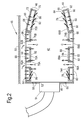
Figure 2 is an enlarged cross-sectional view through the combustion chamber shown infigure 1 . -
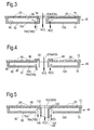
Figure 3 is an enlarged cross-sectional view of a wall and a mixing port in the wall of the combustion chamber shown infigure 2 . -
Figure 4 is an alternative enlarged cross-sectional view of a wall and a mixing port in the wall of the combustion chamber shown infigure 2 . -
Figure 5 is another enlarged cross-sectional view of a wall and a mixing port in the wall of the combustion chamber shown infigure 2 . - A turbofan
gas turbine engine 10, as shown infigure 1 , comprises in flow series aninlet 12, afan section 14, acompressor section 16, acombustion section 18, aturbine section 20 and anexhaust 22. Thefan section 14 comprises afan 24. Thecompressor section 16 comprises in flow series anintermediate pressure compressor 26 and ahigh pressure compressor 28. Theturbine section 20 comprises in flow series ahigh pressure turbine 30, anintermediate pressure turbine 32 and alow pressure turbine 34. Thefan 24 is driven by thelow pressure turbine 34 via ashaft 40. Theintermediate pressure compressor 26 is driven by theintermediate pressure turbine 32 via ashaft 38 and thehigh pressure compressor 28 is driven by thehigh pressure turbine 30 via ashaft 36. The turbofangas turbine engine 10 operates quite conventionally and its operation will not be discussed further. The turbofangas turbine engine 10 has a rotational axis X. - The
combustion section 18 comprises anannular combustion chamber 42, which is shown more clearly infigure 2 . Theannular combustion chamber 42 has a radially innerannular wall 44, a radially outerannular wall 46 and anupstream wall 48 connecting the upstream ends of the radially innerannular wall 44 and the radially outerannular wall 46. Theannular combustion chamber 42 is surrounded by acasing 50. Theupstream wall 48 has a plurality of circumferentially spacedfuel injector apertures 52 and eachfuel injector aperture 52 has a respective one of a plurality offuel injectors 54. Theupstream wall 48 also has a plurality of smallerdiameter cooling apertures 56 through which a flow of coolant, air, is arranged to flow in operation. The radially innerannular wall 44 has a plurality of circumferentially spaced mixing ports 58 through which a flow of mixing air is arranged to flow into theannular combustion chamber 42 in operation. The radially outerannular wall 46 has a plurality of circumferentially spaced mixing ports 62 through which a flow of mixing air is arranged to flow into theannular combustion chamber 42 in operation. The fuel injector apertures 52 in theupstream wall 48 define inlets for primary air for theannular combustion chamber 42. - The radially inner
annular wall 44 is a double skin annular wall and the radially outerannular wall 46 is a double skin annular wall. The radially innerannular wall 44 comprises a radiallyinner wall 66 and a radiallyouter wall 68 and the radially outerannular wall 46 comprises a radiallyinner wall 70 and a radiallyouter wall 72. The radiallyouter wall 68 of the radially innerannular wall 44 comprises a plurality oftiles inner wall 70 of the radially outerannular wall 46 comprises a plurality oftiles annular wall 44 has a plurality of circumferentially spacedprimary mixing ports 58A extending there-through and a plurality of circumferentially spacedsecondary mixing ports 58B extending there-through and thesecondary mixing ports 58B are arranged downstream of theprimary mixing ports 58A. The double skin radially outerannular wall 46 has a plurality of circumferentially spacedprimary mixing ports 62A extending there-through and a plurality of circumferentially spacedsecondary mixing ports 62B extending there-through and thesecondary mixing ports 62B are arranged downstream of theprimary mixing ports 62A. The radiallyouter wall 68 of the double skin radiallyinner wall 44 has a plurality of circumferentially spaced additionalprimary mixing ports 74A extending there-through adjacent theprimary mixing ports 58A, the radiallyouter wall 68 of the double skin radiallyinner wall 44 also has a plurality of circumferentially spaced additionalsecondary mixing ports 74B extending there-through adjacent thesecondary mixing ports 58B. The radiallyinner wall 70 of the double skin radiallyouter wall 46 has a plurality of circumferentially spaced additionalprimary mixing ports 76A extending there-through adjacent theprimary mixing ports 62A, the radiallyinner wall 70 of the double skin radiallyouter wall 46 also has a plurality of circumferentially spaced additionalsecondary mixing ports 76B extending there-through adjacent thesecondary mixing ports 62B. Each of the additionalprimary mixing ports 74A is arranged around the respectiveprimary mixing port 58A and each of the additionalsecondary mixing ports 74B is arranged around the respectivesecondary mixing port 58B. Similarly each of the additionalprimary mixing ports 76A is arranged around the respectiveprimary mixing port 62A and each of the additionalsecondary mixing ports 76B is arranged around the respectivesecondary mixing port 62B. - The radially
inner wall 66 of the double skin radially innerannular wall 44 also has a plurality of smallerdiameter cooling apertures 60 through which a flow of coolant, air, is arranged to flow in operation. The coolant, air, is arranged to flow through theapertures 60 intochambers 80 defined between the radiallyinner wall 66 and thetiles outer wall 68 of the double skin radiallyinner wall 44. The coolant is arranged to impinge upon the radiallyinner surfaces 82 of thetiles inner surfaces 82 of thetiles tiles tiles outer wall 68 of the double skin radially innerannular wall 44 have a plurality ofeffusion cooling apertures 78 through which a flow of coolant, air, is arranged to flow in operation from thechambers 80 and over the radiallyouter surfaces 84 of thetiles chambers 80 is arranged to flow through the additionalprimary mixing ports 74A and the additional secondary mixingports 74B. - The radially
outer wall 72 of the double skin radially outerannular wall 46 also has a plurality of smallerdiameter cooling apertures 64 through which a flow of coolant, air, is arranged to flow in operation. The coolant, air, is arranged to flow through theapertures 64 intochambers 88 defined between the radiallyouter wall 72 and thetiles inner wall 70 of the double skin radiallyouter wall 46. The coolant is arranged to impinge upon the radiallyouter surfaces 90 of thetiles outer surfaces 90 of thetiles tiles tiles inner wall 70 of the double skin radially outerannular wall 46 have a plurality ofeffusion cooling apertures 86 through which a flow of coolant, air, is arranged to flow in operation from thechambers 88 and over the radiallyinner surfaces 92 of thetiles chambers 88 is arranged to flow through the additionalprimary mixing ports 76A and the additional secondary mixingports 76B. - In
operation 10% of the air for thecombustion chamber 42 is supplied through the inlets, thefuel injector apertures 52, in theupstream wall annular wall 44 and the double skin radially outerannular wall 46 and theupstream wall 48. A first portion A of the 32% to 40% of the air for primary mixing is supplied through theprimary mixing ports annular wall 44 and the double skin radially outerannular wall 46 respectively into thecombustion chamber 42. A second portion B of the 32% to 40% of the air for primary mixing provides convective cooling of the double skin radially innerannular wall 44 and the double skin radially outerannular wall 46 before it is supplied through the additionalprimary mixing ports outer wall 68 of the double skin radially innerannular wall 44 and in the radiallyinner wall 70 of the double skin radially outerannular wall 46 respectively into thecombustion chamber 42. A first portion C of the 32% to 40% of the air for secondary mixing is supplied through the secondary mixingports annular wall 44 and the double skin radially outerannular wall 46 respectively into thecombustion chamber 42. A second portion D of the 32% to 40% of the air for secondary mixing provides convective cooling of the double skin radially innerannular wall 44 and the double skin radially outerannular wall 46 before it is supplied through the additional secondary mixingports outer wall 68 of the double skin radially innerannular wall 44 and in the radiallyinner wall 70 of the double skin radially outerannular wall 46 respectively into thecombustion chamber 42. Inaddition 10% to 26% of the air is used for cooling the double skin radially innerannular wall 44 and the double skin radially outerannular wall 46 and theupstream wall 48 provides convective cooling and/or effusion cooling of the double skin radially innerannular wall 44, the double skin radially outerannular wall 46 and theupstream wall 48. - In an example, 35% to 40% of the air is supplied for primary mixing, 35% to 40% of the air is supplied for secondary mixing and 10% to 20% of the air is supplied for cooling the double skin radially inner
annular wall 44 and the double skin radially outerannular wall 46 and theupstream wall 48. A first portion A of the 35% to 40% of the air for primary mixing is supplied through theprimary mixing ports annular wall 44 and the double skin radially outerannular wall 46 respectively into thecombustion chamber 42. A second portion B of the 35% to 40% of the air for primary mixing provides convective cooling of the double skin radially innerannular wall 44 and the double skin radially outerannular wall 46 before it is supplied through the additionalprimary mixing ports outer wall 68 of the double skin radially innerannular wall 44 and in the radiallyinner wall 70 of the double skin radially outerannular wall 46 respectively into thecombustion chamber 42. A first portion C of the 35% to 40% of the air for secondary mixing is supplied through the secondary mixingports annular wall 44 and the double skin radially outerannular wall 46 respectively into thecombustion chamber 42. A second portion D of the 35% to 40% of the air for secondary mixing provides convective cooling of the double skin radially innerannular wall 44 and the double skin radially outerannular wall 46 before it is supplied through the additional secondary mixingports outer wall 68 of the double skin radially innerannular wall 44 and in the radiallyinner wall 70 of the double skin radially outerannular wall 46 respectively into thecombustion chamber 42. Inaddition 10% to 20% of the air is used for cooling the double skin radially innerannular wall 44 and the double skin radially outerannular wall 46 and theupstream wall 48 provides convective cooling and/or effusion cooling of the double skin radially innerannular wall 44, the double skin radially outerannular wall 46 and theupstream wall 48. - In a more specific example, 40% of the air is supplied for primary mixing, 40% of the air is supplied for secondary mixing and 10% of the air is supplied for cooling the double skin radially inner
annular wall 44 and the double skin radially outerannular wall 46 and theupstream wall 48. A first portion A of the 40% of the air for primary mixing is supplied through theprimary mixing ports annular wall 44 and the double skin radially outerannular wall 46 respectively into thecombustion chamber 42. A second portion B of the 40% of the air for primary mixing provides convective cooling of the double skin radially innerannular wall 44 and the double skin radially outerannular wall 46 before it is supplied through the additionalprimary mixing ports outer wall 68 of the double skin radially innerannular wall 44 and in the radiallyinner wall 70 of the double skin radially outerannular wall 46 respectively into thecombustion chamber 42. A first portion C of the 40% of the air for secondary mixing is supplied through the secondary mixingports annular wall 44 and the double skin radially outerannular wall 46 respectively into thecombustion chamber 42. A second portion D of the 40% of the air for secondary mixing provides convective cooling of the double skin radially innerannular wall 44 and the double skin radially outerannular wall 46 before it is supplied through the additional secondary mixingports outer wall 68 of the double skin radially innerannular wall 44 and in the radiallyinner wall 70 of the double skin radially outerannular wall 46 respectively into thecombustion chamber 42. Inaddition 10% of the air is used for cooling the double skin radially innerannular wall 44 and the double skin radially outerannular wall 46 and theupstream wall 48 provides convective cooling and/or effusion cooling of the double skin radially innerannular wall 44, the double skin radially outerannular wall 46 and theupstream wall 48. - In the examples given above half of the air for mixing is supplied through the mixing
ports combustion chamber 42 and half of the air for mixing is used to provide impingement and/or convective cooling of the double skin radially innerannular wall 44 and the double skin radially outerannular wall 46 before being supplied through theadditional mixing ports combustion chamber 42. In particular half of the air for primary mixing A is supplied through theprimary mixing ports combustion chamber 42 and half of the air for primary mixing B is used to provide impingement and/or convective cooling of the double skin radially innerannular wall 42 and the double skin radially outerannular wall 46 before being supplied through the additionalprimary mixing ports combustion chamber 42 and half of the air for secondary mixing C is supplied through the secondary mixingports combustion chamber 42 and half of the air for secondary mixing D is used to provide impingement and/or convective cooling of the double skin radially innerannular wall 44 and the double skin radially outerannular wall 46 before being supplied through the additional secondary mixingports combustion chamber 42. -
Figure 3 shows an embodiment of the double skin radially outerannular wall 46 and shows atile 70A of the radiallyinner wall 70 and the radiallyouter wall 72. The radiallyouter wall 72 hasapertures 64 to provide impingement cooling of the radiallyouter surface 90 of thetiles 70A, alternatively the radiallyouter surface 90 of thetiles 70A may be convectively cooled or the radiallyouter surface 90 of thetiles 70A may be provided with radially outwardly extending ribs, or projections, to provide cooling of thetiles 70A. Each mixingport 62A is defined by aboss 94 which is integral, e.g. cast integral, with thetile 70A and abuts the radially inner surface of the radiallyouter wall 72. Each additional mixingport tile 70A which are arranged around, e.g. concentrically around, theboss 94. -
Figure 4 shows another embodiment of the double skin radially outerannular wall 46 and shows atile 70A of the radiallyinner wall 70 and the radiallyouter wall 72. The radiallyouter wall 72 hasapertures 64 to provide impingement cooling of the radiallyouter surface 90 of thetiles 70A, alternatively the radiallyouter surface 90 of thetiles 70A may be convectively cooled or the radiallyouter surface 90 of thetiles 70A may be provided with radially outwardly extending ribs, or projections, to provide cooling of thetiles 70A. Thetiles 70A also haveeffusion cooling apertures 86 at predetermined locations to cool hot spots on thetiles 70A. Each mixingport 62A is defined by a boss 96 which extends radially through the radiallyouter wall 72 and atile 70A of the radiallyinner wall 70 and the boss 96 has aflange 98 which abuts, and is secured to, the radially outer surface of the radiallyouter wall 72. Each additional mixingport tile 70A and the boss 96. Each additional mixingport -
Figure 5 shows a further embodiment of the double skin radially outerannular wall 46 and shows atile 70A of the radiallyinner wall 70 and the radiallyouter wall 72. The radiallyouter wall 72 hasapertures 64 to provide impingement cooling of the radiallyouter surface 90 of thetiles 70A, alternatively the radiallyouter surface 90 of thetiles 70A may be convectively cooled or the radiallyouter surface 90 of thetiles 70A may be provided with radially outwardly extending ribs, or projections, to provide cooling of thetiles 70A. Each mixingport 62A is defined by aboss 100 which extends radially through thetile 70A of the radiallyinner wall 70 and theboss 100 has aflange 102 which abuts, and is secured to, the radially inner surface of the radiallyouter wall 72. Each additional mixingport tile 70A and theboss 100. Each additional mixingport boss 100. Eachboss 100 has aportion 104 which extends radially into thecombustion chamber 42 and enhances mixing in thecombustion chamber 42. Theportion 104 is chamfered such that thedownstream end 106 extends radially further into thecombustion chamber 42 than theupstream end 108. The additional mixing air flowing through the additional mixingport boss 100 extending into thecombustion chamber 42. - Although the present invention has been described with reference to an annular combustion chamber comprising a radially inner double skinned annular wall and a radially outer double skinned annular wall, the present invention is equally applicable to a tubular combustion chamber comprising a single double skinned annular wall.
- The present invention provides more air than is currently supplied for mixing purposes. The present invention uses some, or all, of the air currently used to provide film cooling of the inner wall of the double skinned annular wall(s) to provide convection cooling and/or effusion cooling of the double skinned annular wall(s) and this air is then supplied through the additional mixing port in the inner wall of the double skinned annular wall(s) to function as mixing air to provide supplementary mixing air. The present invention provides these additional mixing ports adjacent to, around, the mixing ports. The additional mixing ports may be concentric annular slots around the mixing ports or as a plurality of slots arranged concentrically with the mixing ports. In addition, the present invention uses some of the air currently supplied through the mixing ports and used as mixing air to provide convection cooling and/or effusion cooling of the double skinned annular wall(s) and this air is then supplied through the additional mixing port in the inner wall of the double skinned annular wall(s) to function as mixing air to provide supplementary mixing air.
- In the present invention the air supplied through the mixing ports is used as an ejector, or energiser, for the air supplied through the corresponding additional mixing port.
- The advantage of the present invention is that it increases the amount of air available for mixing in a "rich burn" combustion chamber and therefore improves the mixing process within the combustion chamber and hence reduces engine emissions. In addition the present invention significantly increases the amount of air available for cooling of the double skinned annular wall(s) compared to current designs. The increased mass flow of air for cooling of the double skinned annular wall(s) reduces the level of temperature rise in the cooling air, so improving the cooling performance and at the same time any temperature rise that does occur in the cooling air is beneficial in improving the mixing performance in the combustion chamber, because this spent cooling air is supplied through the additional mixing port(s). The supply of mixing air through the double skinned annular wall(s) results in a pressure drop in the cooling air and hence in the cooling air supplied through the additional mixing port(s) as mixing air. This pressure drop reduces the ability of the cooling air flowing through the additional mixing port(s) to mix efficiently with the combustion products in the combustion chamber. That is why the present invention does not supply all the air required for mixing through the double skinned annular wall(s) to cool the double skinned annular wall(s) before being used as mixing air. An optimum use of the air is to supply half of the air directly through the mixing port(s) as mixing air and to supply half of the air for cooling the double skinned annular wall(s) and then through the additional mixing port(s) as mixing air so as to provide sufficient momentum to achieve efficient mixing of the mixing air and combustion products in the combustion chamber.
Claims (14)
- A method of operating a combustion chamber (42), the combustion chamber (42) comprising an upstream wall (48) having at least one inlet (52) for a fuel injector (54) and primary air, at least one double skin annular wall (44, 46), the at least one double skin annular wall (44, 46) comprising an inner wall (66, 70) and an outer wall (68, 72), the at least one double skin annular wall (44, 46) having at least one mixing port (58A, 58B, 62A, 62B) extending there-through, the inner wall (66, 70) or the outer wall (68, 72) having at least one additional mixing port (74A, 74B, 76A, 76B) extending there-through adjacent the mixing port (58A, 58B, 62A, 62B),
the method comprising supplying air for the combustion chamber (42),
the method comprising supplying 10% of the air for the combustion chamber (42) through the inlet (52) in the upstream wall (48), supplying 64% to 80% of the air for mixing, and supplying 10% to 26% of the air for cooling the at least one double skin annular wall (44,46) and the upstream wall (48),
the method further comprising supplying a first portion of the 64% to 80% of the air for mixing through the at least one mixing port (58A, 58B, 62A, 62B) into the combustion chamber (42) and supplying a second portion of the 64% to 80% of the air for mixing to provide convective cooling of the at least one double skin annular wall (44, 46) before being supplied through the additional mixing port (74A, 74B, 76A, 76B) into the combustion chamber (42) and supplying the 10% to 26% of the air for cooling the at least one double skin annular wall (44, 46) and the upstream wall (48) to provide convective cooling and/or effusion cooling of the at least one double skin annular wall (44, 46) and the upstream wall (48). - A method as claimed in claim 1 wherein the at least one mixing port (58A, 58B, 62A, 62B) extending through the at least one double skin annular wall (44, 46) comprising at least one primary mixing port (58A, 62A) extending through the at least one double skin annular wall (44, 46) and at least one secondary mixing port (58B, 62B) extending through the at least one double skin annular wall (44, 46) and arranged downstream of the at least one primary mixing port (58A, 62A), the at least one additional mixing port (74A, 74B, 76A, 76B) in the inner wall (66, 70) or outer wall (68, 72) comprising at least one additional primary mixing port (74A, 76A) extending through the inner wall (66, 70) or the outer wall (68, 72) adjacent the primary mixing port (58A, 62A) and at least one additional secondary mixing port (74B, 76B) extending through the inner wall (66, 70) or the outer wall (68, 72) adjacent the secondary mixing port (58B, 62B),
the method comprising supplying 10% of the air for the combustion chamber (42) through the inlet (52) in the upstream wall (48), supplying 32% to 40% of the air for primary mixing, supplying 32% to 40% of the air for secondary mixing and supplying 10% to 26% of the air for cooling the at least one double skin annular wall (44, 46) and the upstream wall (48),
the method further comprising supplying a first portion of the 32% to 40% of the air for primary mixing through the at least one primary mixing port (58A, 62A) into the combustion chamber (42) and supplying a second portion of the 32% to 40% of the air for primary mixing to provide convective cooling of the at least one double skin annular wall (44, 46) before being supplied through the at least one additional primary mixing port (74A, 76A) into the combustion chamber (42), supplying a first portion of the 32% to 40% of the air for secondary mixing through the at least one secondary mixing port (58B, 62B) into the combustion chamber (42) and supplying a second portion of the 32% to 40% of the air for secondary mixing to provide convective cooling of the at least one double skin annular wall (44, 46) before being supplied through the at least one additional secondary mixing port ( 74B, 76B) into the combustion chamber (42) and supplying the 10% to 26% of the air for cooling the at least one double skin annular wall (44, 46) and the upstream wall (48) to provide convective cooling and/or effusion cooling of the at least one double skin annular wall (44, 46) and the upstream wall (48). - A method as claimed in claim 2 comprising supplying 10% of the air for the combustion chamber (42) through the inlet (52) in the upstream wall (48), supplying 35% to 40% of the air for primary mixing, supplying 35% to 40% of the air for secondary mixing and supplying 10% to 20% of the air for cooling the at least one double skin annular wall (44, 46) and the upstream wall (48),
the method further comprising supplying a first portion of the 35% to 40% of the air for primary mixing through the at least one primary mixing port (58A, 62A) into the combustion chamber (42) and supplying a second portion of the 35% to 40% of the air for primary mixing to provide convective cooling of the at least one double skin annular wall (44, 46) before being supplied through the at least one additional primary mixing port (74A, 76A) into the combustion chamber (42), supplying a first portion of the 35% to 40% of the air for secondary mixing through the at least one secondary mixing port (58B, 62B) into the combustion chamber (42) and supplying a second portion of the 35% to 40% of the air for secondary mixing to provide convective cooling of the at least one double skin annular wall (44, 46) before being supplied through the at least one additional secondary mixing port (74B, 76B) into the combustion chamber (42) and supplying the 10% to 20% of the air for cooling the at least one double skin annular wall (44, 46) and the upstream wall (48) to provide convective cooling and/or effusion cooling of the at least one double skin annular wall (44, 46) and the upstream wall (48). - A method as claimed in claim 2 or claim 3 comprising supplying 10% of the air for the combustion chamber (42) through the inlet (52) in the upstream wall (48), supplying 40% of the air for primary mixing, supplying 40% of the air for secondary mixing and supplying 10% of the air for cooling the at least one double skin annular wall (44, 46) and the upstream wall (48),
the method further comprising supplying a first portion of the 40% of the air for primary mixing through the at least one primary mixing port (58A, 62A) into the combustion chamber (42) and supplying a second portion of the 40% of the air for primary mixing to provide convective cooling of the at least one double skin annular wall (44, 46) before being supplied through the at least one additional primary mixing port (74A, 76A) into the combustion chamber (42), supplying a first portion of the 40% of the air for secondary mixing through the at least one secondary mixing port (58B, 62B) into the combustion chamber (42) and supplying a second portion of the 40% of the air for secondary mixing to provide convective cooling of the at least one double skin annular wall (44, 46) before being supplied through the at least one additional secondary mixing port (74B, 76B) into the combustion chamber (42) and supplying the 10% of the air for cooling the at least one double skin annular wall (44, 46) and the upstream wall (48) to provide convective cooling and effusion cooling of the at least one double skin annular wall (44, 46) and/or the upstream wall (48). - A method as claimed in claim 2, claim 3 or claim 4 comprising supplying half of the air for primary mixing through the at least one primary mixing port (58A, 62A) into the combustion chamber (42) and supplying half of the air for primary mixing to provide convective cooling of the at least one double skin annular wall (44, 46) before being supplied through the at least one additional primary mixing port (74A, 76A) into the combustion chamber (42).
- A method as claimed in any of claims 2 to 5 comprising supplying half of the air for secondary mixing through the at least one secondary mixing port (58B, 62B) into the combustion chamber (42) and supplying half of the air for secondary mixing to provide convective cooling of the at least one double skin annular wall (44, 46) before being supplied through the at least one additional secondary mixing port (74B, 76B) into the combustion chamber (42).
- A method as claimed in any of claims 2 to 6 wherein the at least one double skinned annular wall (44, 46) comprises a plurality of circumferentially spaced primary mixing ports (58A, 62A) and a plurality of circumferentially spaced secondary mixing ports (58B, 62B).
- A method as claimed in any of claims 2 to 7 wherein the at least one double skinned annular wall (44, 46) comprises a plurality of circumferentially spaced additional primary mixing ports (74A, 76A) and a plurality of circumferentially spaced additional secondary mixing ports (74B, 76B).
- A method as claimed in any of claims 2 to 8 wherein the at least one additional primary mixing port (74A, 76A) is arranged around the at least one primary mixing port (58A, 62A).
- A method as claimed in any of claims 2 to 9 wherein the at least one additional secondary mixing port (74B, 76B) is arranged around the at least one secondary mixing port (58B, 62B).
- A method as claimed in claim 1 comprising supplying half of the air for mixing through the at least one mixing port (58A, 58B, 62A, 62B) into the combustion chamber (42) and supplying half of the air for mixing to provide convective cooling of the at least one double skin annular wall (44, 46) before being supplied through the at least one additional mixing port (74A, 74B, 76A, 76B) into the combustion chamber (42).
- A method as claimed in any of claims 1 to 11 wherein the combustion chamber (42) is an annular combustion chamber comprising a radially inner double skinned annular wall (44) and a radially outer double skinned annular wall (46).
- A method as claimed in any of claims 1 to 11 wherein the combustion chamber is a tubular combustion chamber comprising a single double skinned annular wall.
- A method as claimed in any of claims 1 to 13 wherein the combustion chamber (42) is a gas turbine engine combustion chamber.
Applications Claiming Priority (1)
| Application Number | Priority Date | Filing Date | Title |
|---|---|---|---|
| GBGB1116608.9A GB201116608D0 (en) | 2011-09-27 | 2011-09-27 | A method of operating a combustion chamber |
Publications (2)
| Publication Number | Publication Date |
|---|---|
| EP2574846A2 true EP2574846A2 (en) | 2013-04-03 |
| EP2574846A3 EP2574846A3 (en) | 2017-10-18 |
Family
ID=44994018
Family Applications (1)
| Application Number | Title | Priority Date | Filing Date |
|---|---|---|---|
| EP12184230.6A Withdrawn EP2574846A3 (en) | 2011-09-27 | 2012-09-13 | A method of operating a combustion chamber |
Country Status (3)
| Country | Link |
|---|---|
| US (1) | US20130078582A1 (en) |
| EP (1) | EP2574846A3 (en) |
| GB (1) | GB201116608D0 (en) |
Cited By (1)
| Publication number | Priority date | Publication date | Assignee | Title |
|---|---|---|---|---|
| US10823413B2 (en) | 2016-08-01 | 2020-11-03 | Rolls-Royce Plc | Combustion chamber assembly and a combustion chamber segment |
Families Citing this family (17)
| Publication number | Priority date | Publication date | Assignee | Title |
|---|---|---|---|---|
| US9360215B2 (en) * | 2012-04-02 | 2016-06-07 | United Technologies Corporation | Combustor having a beveled grommet |
| US20150354819A1 (en) * | 2013-01-16 | 2015-12-10 | United Technologies Corporation | Combustor Cooled Quench Zone Array |
| WO2015030927A1 (en) * | 2013-08-30 | 2015-03-05 | United Technologies Corporation | Contoured dilution passages for a gas turbine engine combustor |
| EP3039340B1 (en) * | 2013-08-30 | 2018-11-28 | United Technologies Corporation | Vena contracta swirling dilution passages for gas turbine engine combustor |
| WO2015039075A1 (en) | 2013-09-16 | 2015-03-19 | United Technologies Corporation | Angled combustor liner cooling holes through transverse structure within a gas turbine engine combustor |
| EP3099976B1 (en) * | 2014-01-30 | 2019-03-13 | United Technologies Corporation | Cooling flow for leading panel in a gas turbine engine combustor |
| US10533745B2 (en) * | 2014-02-03 | 2020-01-14 | United Technologies Corporation | Film cooling a combustor wall of a turbine engine |
| US20160178199A1 (en) * | 2014-12-17 | 2016-06-23 | United Technologies Corporation | Combustor dilution hole active heat transfer control apparatus and system |
| US10132498B2 (en) * | 2015-01-20 | 2018-11-20 | United Technologies Corporation | Thermal barrier coating of a combustor dilution hole |
| DE102016207057A1 (en) * | 2016-04-26 | 2017-10-26 | Rolls-Royce Deutschland Ltd & Co Kg | Gas turbine combustor |
| US11221143B2 (en) | 2018-01-30 | 2022-01-11 | General Electric Company | Combustor and method of operation for improved emissions and durability |
| US11313560B2 (en) | 2018-07-18 | 2022-04-26 | General Electric Company | Combustor assembly for a heat engine |
| US11719438B2 (en) * | 2021-03-15 | 2023-08-08 | General Electric Company | Combustion liner |
| CN113551258B (en) * | 2021-08-31 | 2025-02-11 | 西北工业大学 | Truss type double wall heat insulation device for engine combustion chamber and cold air film forming method |
| US12222104B2 (en) * | 2022-03-21 | 2025-02-11 | General Electric Company | Turbine engine combustor and combustor liner |
| US11739935B1 (en) * | 2022-03-23 | 2023-08-29 | General Electric Company | Dome structure providing a dome-deflector cavity with counter-swirled airflow |
| US12259133B2 (en) * | 2023-02-15 | 2025-03-25 | Rtx Corporation | Cooling combustor wall boss |
Family Cites Families (32)
| Publication number | Priority date | Publication date | Assignee | Title |
|---|---|---|---|---|
| BE514534A (en) * | 1951-05-31 | |||
| US2974485A (en) * | 1958-06-02 | 1961-03-14 | Gen Electric | Combustor for fluid fuels |
| FR1500110A (en) * | 1966-07-08 | 1967-11-03 | Snecma | Improvements to turbo-reactors |
| US4480436A (en) * | 1972-12-19 | 1984-11-06 | General Electric Company | Combustion chamber construction |
| US4109459A (en) * | 1974-07-19 | 1978-08-29 | General Electric Company | Double walled impingement cooled combustor |
| GB1550368A (en) * | 1975-07-16 | 1979-08-15 | Rolls Royce | Laminated materials |
| GB2017827B (en) * | 1978-04-04 | 1983-02-02 | Gen Electric | Combustor liner cooling |
| US4302941A (en) * | 1980-04-02 | 1981-12-01 | United Technologies Corporation | Combuster liner construction for gas turbine engine |
| GB2087065B (en) * | 1980-11-08 | 1984-11-07 | Rolls Royce | Wall structure for a combustion chamber |
| US4688310A (en) * | 1983-12-19 | 1987-08-25 | General Electric Company | Fabricated liner article and method |
| US4622821A (en) * | 1985-01-07 | 1986-11-18 | United Technologies Corporation | Combustion liner for a gas turbine engine |
| US4790140A (en) * | 1985-01-18 | 1988-12-13 | Ishikawajima-Harima Jukogyo Kabushiki Kaisha | Liner cooling construction for gas turbine combustor or the like |
| US4744670A (en) * | 1986-05-05 | 1988-05-17 | Honeywell, Inc. | Method and apparatus for monitoring the temperature of the propulsion gas at the inlet to a high-performance turbine wheel |
| US4838031A (en) * | 1987-08-06 | 1989-06-13 | Avco Corporation | Internally cooled combustion chamber liner |
| JP2543981B2 (en) * | 1989-05-23 | 1996-10-16 | 株式会社東芝 | Gas turbine combustor |
| DE19547703C2 (en) * | 1995-12-20 | 1999-02-18 | Mtu Muenchen Gmbh | Combustion chamber, in particular ring combustion chamber, for gas turbine engines |
| US6079199A (en) * | 1998-06-03 | 2000-06-27 | Pratt & Whitney Canada Inc. | Double pass air impingement and air film cooling for gas turbine combustor walls |
| US6155056A (en) * | 1998-06-04 | 2000-12-05 | Pratt & Whitney Canada Corp. | Cooling louver for annular gas turbine engine combustion chamber |
| US6279323B1 (en) * | 1999-11-01 | 2001-08-28 | General Electric Company | Low emissions combustor |
| GB2373319B (en) * | 2001-03-12 | 2005-03-30 | Rolls Royce Plc | Combustion apparatus |
| US6546733B2 (en) * | 2001-06-28 | 2003-04-15 | General Electric Company | Methods and systems for cooling gas turbine engine combustors |
| US6495207B1 (en) * | 2001-12-21 | 2002-12-17 | Pratt & Whitney Canada Corp. | Method of manufacturing a composite wall |
| US20050034399A1 (en) * | 2002-01-15 | 2005-02-17 | Rolls-Royce Plc | Double wall combustor tile arrangement |
| DE10214570A1 (en) * | 2002-04-02 | 2004-01-15 | Rolls-Royce Deutschland Ltd & Co Kg | Mixed air hole in gas turbine combustion chamber with combustion chamber shingles |
| EP1650503A1 (en) * | 2004-10-25 | 2006-04-26 | Siemens Aktiengesellschaft | Method for cooling a heat shield element and a heat shield element |
| US7954325B2 (en) * | 2005-12-06 | 2011-06-07 | United Technologies Corporation | Gas turbine combustor |
| EP1832812A3 (en) * | 2006-03-10 | 2012-01-04 | Rolls-Royce Deutschland Ltd & Co KG | Gas turbine combustion chamber wall with absorption of combustion chamber vibrations |
| DE102006026969A1 (en) * | 2006-06-09 | 2007-12-13 | Rolls-Royce Deutschland Ltd & Co Kg | Gas turbine combustor wall for a lean-burn gas turbine combustor |
| DE102007018061A1 (en) * | 2007-04-17 | 2008-10-23 | Rolls-Royce Deutschland Ltd & Co Kg | Gas turbine combustion chamber wall |
| FR2921463B1 (en) * | 2007-09-26 | 2013-12-06 | Snecma | COMBUSTION CHAMBER OF A TURBOMACHINE |
| US7905094B2 (en) * | 2007-09-28 | 2011-03-15 | Honeywell International Inc. | Combustor systems with liners having improved cooling hole patterns |
| US8307657B2 (en) * | 2009-03-10 | 2012-11-13 | General Electric Company | Combustor liner cooling system |
-
2011
- 2011-09-27 GB GBGB1116608.9A patent/GB201116608D0/en not_active Ceased
-
2012
- 2012-09-13 EP EP12184230.6A patent/EP2574846A3/en not_active Withdrawn
- 2012-09-13 US US13/614,580 patent/US20130078582A1/en not_active Abandoned
Non-Patent Citations (1)
| Title |
|---|
| None |
Cited By (1)
| Publication number | Priority date | Publication date | Assignee | Title |
|---|---|---|---|---|
| US10823413B2 (en) | 2016-08-01 | 2020-11-03 | Rolls-Royce Plc | Combustion chamber assembly and a combustion chamber segment |
Also Published As
| Publication number | Publication date |
|---|---|
| EP2574846A3 (en) | 2017-10-18 |
| GB201116608D0 (en) | 2011-11-09 |
| US20130078582A1 (en) | 2013-03-28 |
Similar Documents
| Publication | Publication Date | Title |
|---|---|---|
| EP2574846A2 (en) | A method of operating a combustion chamber | |
| EP2211105A2 (en) | Turbulated combustor aft-end liner assembly and related cooling method | |
| EP2481983B1 (en) | Turbulated Aft-End liner assembly and cooling method for gas turbine combustor | |
| EP2375167B1 (en) | Combustor exit temperature profile control via fuel staging and related method | |
| EP3155233B1 (en) | Gas turbine engine with rotor centering cooling system in an exhaust diffuser | |
| US9010124B2 (en) | Cooled double walled article | |
| US9140454B2 (en) | Bundled multi-tube nozzle for a turbomachine | |
| EP2613083B1 (en) | Fuel nozzle assembly for use in a turbine engine and methods of assembling same | |
| EP2927428B1 (en) | Cooled airfoil of a turbine engine | |
| EP2559947B1 (en) | Micromixer Heat Shield | |
| JP2009085222A (en) | Rear end liner assembly with turbulator and cooling method thereof | |
| EP3032176B1 (en) | Fuel injector guide(s) for a turbine engine combustor | |
| EP3171086A1 (en) | Combustor wall channel cooling system | |
| US20160252249A1 (en) | Combustor wall with tapered cooling cavity | |
| CA2936200C (en) | Combustor cooling system | |
| CA2853444A1 (en) | Combustor chamber cooling | |
| CN106989416B (en) | For the burner inner liner used in burner assembly and manufacturing method | |
| EP2634489A1 (en) | Fuel nozzle assembly for use in turbine engines and method of assembling same | |
| EP3032174B1 (en) | Counter-swirl doublet combustor with plunged holes | |
| US9709277B2 (en) | Fuel plenum premixing tube with surface treatment | |
| CN109416180B (en) | Combustor assembly for use in a turbine engine and method of assembling the same | |
| JP2018506693A (en) | Combustor inlet mixing system with swirler vanes having slots | |
| US20120134782A1 (en) | Purge systems for rotary machines and methods of assembling same | |
| WO2015102736A2 (en) | Gas turbine engine quench pattern for gas turbine engine combustor |
Legal Events
| Date | Code | Title | Description |
|---|---|---|---|
| PUAI | Public reference made under article 153(3) epc to a published international application that has entered the european phase |
Free format text: ORIGINAL CODE: 0009012 |
|
| AK | Designated contracting states |
Kind code of ref document: A2 Designated state(s): AL AT BE BG CH CY CZ DE DK EE ES FI FR GB GR HR HU IE IS IT LI LT LU LV MC MK MT NL NO PL PT RO RS SE SI SK SM TR |
|
| AX | Request for extension of the european patent |
Extension state: BA ME |
|
| RAP1 | Party data changed (applicant data changed or rights of an application transferred) |
Owner name: ROLLS-ROYCE PLC |
|
| PUAL | Search report despatched |
Free format text: ORIGINAL CODE: 0009013 |
|
| AK | Designated contracting states |
Kind code of ref document: A3 Designated state(s): AL AT BE BG CH CY CZ DE DK EE ES FI FR GB GR HR HU IE IS IT LI LT LU LV MC MK MT NL NO PL PT RO RS SE SI SK SM TR |
|
| AX | Request for extension of the european patent |
Extension state: BA ME |
|
| RIC1 | Information provided on ipc code assigned before grant |
Ipc: F23R 3/50 20060101ALI20170913BHEP Ipc: F23R 3/04 20060101AFI20170913BHEP |
|
| STAA | Information on the status of an ep patent application or granted ep patent |
Free format text: STATUS: THE APPLICATION HAS BEEN PUBLISHED |
|
| STAA | Information on the status of an ep patent application or granted ep patent |
Free format text: STATUS: THE APPLICATION IS DEEMED TO BE WITHDRAWN |
|
| 18D | Application deemed to be withdrawn |
Effective date: 20180419 |