EP2375167B1 - Combustor exit temperature profile control via fuel staging and related method - Google Patents
Combustor exit temperature profile control via fuel staging and related method Download PDFInfo
- Publication number
- EP2375167B1 EP2375167B1 EP11161667.8A EP11161667A EP2375167B1 EP 2375167 B1 EP2375167 B1 EP 2375167B1 EP 11161667 A EP11161667 A EP 11161667A EP 2375167 B1 EP2375167 B1 EP 2375167B1
- Authority
- EP
- European Patent Office
- Prior art keywords
- fuel injection
- injection nozzles
- fuel
- combustor
- transition duct
- Prior art date
- Legal status (The legal status is an assumption and is not a legal conclusion. Google has not performed a legal analysis and makes no representation as to the accuracy of the status listed.)
- Active
Links
- 239000000446 fuel Substances 0.000 title claims description 62
- 238000000034 method Methods 0.000 title claims description 7
- 238000002347 injection Methods 0.000 claims description 39
- 239000007924 injection Substances 0.000 claims description 39
- 230000007704 transition Effects 0.000 claims description 37
- 239000007789 gas Substances 0.000 claims description 21
- 238000002485 combustion reaction Methods 0.000 claims description 18
- 239000000567 combustion gas Substances 0.000 claims description 6
- 238000011144 upstream manufacturing Methods 0.000 claims description 5
- 239000003570 air Substances 0.000 description 12
- 238000010304 firing Methods 0.000 description 2
- 239000007788 liquid Substances 0.000 description 2
- 230000000712 assembly Effects 0.000 description 1
- 238000000429 assembly Methods 0.000 description 1
- 238000001816 cooling Methods 0.000 description 1
- 238000010586 diagram Methods 0.000 description 1
- 230000003116 impacting effect Effects 0.000 description 1
- 230000000977 initiatory effect Effects 0.000 description 1
- 210000001503 joint Anatomy 0.000 description 1
- 238000012423 maintenance Methods 0.000 description 1
- 239000002184 metal Substances 0.000 description 1
- 239000000203 mixture Substances 0.000 description 1
- 230000002093 peripheral effect Effects 0.000 description 1
- VEMKTZHHVJILDY-UHFFFAOYSA-N resmethrin Chemical compound CC1(C)C(C=C(C)C)C1C(=O)OCC1=COC(CC=2C=CC=CC=2)=C1 VEMKTZHHVJILDY-UHFFFAOYSA-N 0.000 description 1
- XLYOFNOQVPJJNP-UHFFFAOYSA-N water Substances O XLYOFNOQVPJJNP-UHFFFAOYSA-N 0.000 description 1
Images
Classifications
-
- F—MECHANICAL ENGINEERING; LIGHTING; HEATING; WEAPONS; BLASTING
- F23—COMBUSTION APPARATUS; COMBUSTION PROCESSES
- F23R—GENERATING COMBUSTION PRODUCTS OF HIGH PRESSURE OR HIGH VELOCITY, e.g. GAS-TURBINE COMBUSTION CHAMBERS
- F23R3/00—Continuous combustion chambers using liquid or gaseous fuel
- F23R3/28—Continuous combustion chambers using liquid or gaseous fuel characterised by the fuel supply
- F23R3/34—Feeding into different combustion zones
- F23R3/346—Feeding into different combustion zones for staged combustion
Definitions
- This invention relates generally to gas turbine machinery and specifically, to a can-type combustor configured for late fuel injection for management of the combustor exit temperature profile.
- Gas turbines generally include a compressor, one or more combustors, a fuel injection system and a multi-stage turbine section.
- the compressor pressurizes inlet air which is then turned in direction or reverse-flowed to the combustors where it is used to cool the combustors and also to provide air to the combustion process.
- the combustors themselves are located in a circular arrangement about the turbine rotor, in what is generally referred to as a "can-annular" array, and transition ducts deliver combustion gases from each of the combustors to the first stage of the turbine section.
- each combustor in a typical gas turbine configuration, includes a generally cylindrical combustor casing secured to the turbine casing. Each combustor also includes a flow sleeve and a combustor liner substantially concentrically arranged within the flow sleeve. Both the flow sleeve and combustor liner extend between a double-walled transition duct at their downstream or aft ends, and a combustor liner cap assembly at their upstream or forward ends.
- the outer wall of the transition duct and a portion of the flow sleeve are provided with an arrangement of cooling air supply holes over a substantial portion of their respective surfaces, thereby permitting compressor air to enter the radial space between the inner and outer walls of the transition piece and between the combustor liner and the flow sleeve, and to be reverse-flowed to the upstream portion of the combustor where the airflow is again reversed to flow through the cap assembly and into the combustion chamber within the combustor liner.
- Dry low NOx (DLN) gas turbines typically utilize dual-fuel combustors that have both liquid and gas fuel capability.
- One common arrangement includes five dual-fuel nozzles surrounding a center dual-fuel nozzle, arranged to supply fuel and air to the combustion chamber.
- Exemplary can-type combustors configured for late fuel injection are disclosed in US 6 192 688 B1 and US 2009/0084082 A1 .
- the present invention provides a gas turbine combustor according to claim 1.
- a known gas turbine 10 includes a compressor 12 (also partially shown), a plurality of can-annular-type combustors 14 (one shown), and a turbine section represented here by a single nozzle blade 16.
- the turbine is drivingly connected to the compressor 12 along a common axis, i.e., the rotor axis.
- the compressor 12 pressurizes inlet air which is then reverse flowed to the combustor 14 where it is used to cool the combustor and to provide air to the combustion process.
- the invention is not limited to can-annular type combustors.
- a plurality of combustors 14 are located in an annular array about the axis of the gas turbine.
- a transition duct 18 connects the aft end of each combustor with the inlet end of the turbine to deliver the hot products of combustion to the turbine first stage. Ignition is achieved in the various combustors 14 by means of a spark initiating device in conjunction with crossfire tubes 22 (one shown) in the usual manner.
- Each combustor 14 includes a substantially cylindrical combustor casing 24 which is secured to the turbine casing 26 by means of bolts 28.
- the forward end of the combustor casing is closed by an end cover assembly 30 which includes supply tubes, manifolds and associated valves for feeding gaseous fuel, liquid fuel, air and water to the combustor as well understood in the art.
- the end cover assembly 30 also supports a plurality (for example, three to six) "outer" fuel nozzle assemblies 32 (only one shown in Fig. 1 for purposes of convenience and clarity), arranged in a circular array about a longitudinal axis of the combustor, and one center nozzle (not visible in Fig. 1 ).
- a substantially cylindrical flow sleeve 34 which connects at its aft end to the outer wall 36 of the transition duct 18.
- the flow sleeve 34 is connected at its forward end by means of a radial flange 35 to the combustor casing 24 at a butt joint 37 where fore and aft sections of the combustor casing 24 are joined.
- combustor liner 38 defining a combustion chamber 39, and which is connected at its aft end with the inner wall 40 of the transition duct 18.
- the forward end of the combustor liner 38 is supported by a combustor liner cap assembly 42 which is, in turn, supported within the combustor casing 24 by a plurality of struts and an associated mounting assembly (not shown in detail).
- the outer wall 36 of the transition duct 18 and the flow sleeve 34 may be provided with an array of apertures 44 to permit compressor discharge air to flow through the apertures 44 and into the annular space between the flow sleeve 34 and combustor liner 38 where it reverses flow toward the upstream end of the combustor (as indicated by the flow arrows in Fig. 1 ). This is a well known arrangement that needs no further discussion.
- a modified transition duct 20 is attached to the first stage of the turbine section at the aft end of the duct, defined by a relatively rigid peripheral frame member 46 and additional attachment hardware indicated generally at 48.
- the transition duct frame and attachment hardware are generally known and form no part of this invention.
- the turbine first stage nozzle is represented in Fig. 2 by a plurality of first stage nozzle vanes 50, 52 and 54 it being understood that the nozzle vanes are arranged in an annular array adjacent the blades or buckets attached to the first stage wheel of the turbine rotor (not shown).
- two or more late lean fuel injection nozzles 56,58 are mounted on the transition duct at its aft end 20 proximate the attachment hardware 48 and the rigid frame 46, and extending through the double-walled duct, i.e., outer wall 36 and inner wall 40.
- Fuel is supplied to the injection nozzles 56,58 by means of a manifold 60 and a supply conduit 62 which extends to another manifold (not shown) surrounding the aft ends of the array of can-annular combustors.
- the surrounding manifold will supply fuel to the fuel injection nozzles 56,58 and branch inlets 64,66 associated with each of the several combustor transition ducts.
- the fuel injection nozzles 56,58 may have open upper ends 68,70 respectively which draw compressor discharge air into the nozzles to mix with the fuel supplied by the manifold 60.
- internal swirler devices 72,74 may also be included within the nozzles 56,58 to facilitate mixing of the air and fuel prior to injection into the transition duct 18.
- the size of the open ends 68,70 of the injection nozzles 56,58 would be chosen to draw in the desired amount of air for mixing with the fuel, and thereafter introduced into the transition duct substantially perpendicular to the flow of combustion gases within the duct. Ignition of the mixture may be achieved by any suitable and otherwise conventional means.
- the fuel injection nozzles 56,58 are located so as to be generally circumferentially between downstream pairs of the turbine stage one nozzle vanes 50,52 and 52,54, and on either side of a longitudinal axis of the transition duct.
- the injection nozzle 56 is located circumferentially between the nozzle vanes 50 and 52
- the injection nozzle 58 is located circumferentially between the nozzle vanes 52 and 54.
- three nozzle vanes are located generally within the exit opening profile of the transition duct 20.
- the average temperature profile of the combustor exit temperature may be maintained or even increased without exposing the hot gas path combustor components to peak temperatures.
- the late lean combustion occurs downstream of the combustion chamber 39 which is normally at a higher temperature than the aft end of the transition duct 18.
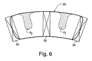
- the peak temperature regions produced by the late lean injection combustion are located away from the duct walls and circumferentially between the first stage nozzle vanes as depicted at P 1 and P 2 in Fig. 6 .
- FIG. 3 Another advantage of the present invention with respect to maintenance of a temperature exit profile but with increased service life of hot gas path components can also be seen from a comparison of Figs. 3 and 4 .
- the average temperature profile and peak temperature pattern are not perfectly symmetrical, indicating a so-called cold streak nearer one side of the transition duct side walls represented by the horizontal lines 76 and 78.
- the fuel feed to the late lean fuel injection nozzles 56,58 may be differentiated to provide more fuel on that side characterized by the cold streak than on the other side of the duct.
- the temperature profile may be made more uniform and, at the same time, and the temperature peak pattern may be diverted away from the side walls of the transition duct as shown in Fig. 4 .
- the peak temperature pattern is engineered away from the transition duct side walls 76,78.
- the peak temperatures can be kept away from the metal parts, while the overall heat into to the turbine can be increased or adjusted to provide more uniform exit temperature profiles. This leads to a longer service life for the components and increased output efficiency for the turbine.
- Fig. 5 illustrates in flowchart form, the various operating conditions of the turbine from start up to full-speed to full-load. More specifically after start up, the turbine is brought up to a full speed no-load condition, and subsequently to a firing temperature that is normally limited by hot gas path component durability.
- the turbine firing temperature can be increased without negatively impacting on the hot gas path durability, and the turbine may be brought to a full-speed full-load condition with acceptable component durability.
Landscapes
- Engineering & Computer Science (AREA)
- Chemical & Material Sciences (AREA)
- Combustion & Propulsion (AREA)
- Mechanical Engineering (AREA)
- General Engineering & Computer Science (AREA)
- Turbine Rotor Nozzle Sealing (AREA)
Description
- This invention relates generally to gas turbine machinery and specifically, to a can-type combustor configured for late fuel injection for management of the combustor exit temperature profile.
- Gas turbines generally include a compressor, one or more combustors, a fuel injection system and a multi-stage turbine section. Typically, the compressor pressurizes inlet air which is then turned in direction or reverse-flowed to the combustors where it is used to cool the combustors and also to provide air to the combustion process. In some multi-combustor turbines, the combustors themselves are located in a circular arrangement about the turbine rotor, in what is generally referred to as a "can-annular" array, and transition ducts deliver combustion gases from each of the combustors to the first stage of the turbine section.
- More specifically, in a typical gas turbine configuration, each combustor includes a generally cylindrical combustor casing secured to the turbine casing. Each combustor also includes a flow sleeve and a combustor liner substantially concentrically arranged within the flow sleeve. Both the flow sleeve and combustor liner extend between a double-walled transition duct at their downstream or aft ends, and a combustor liner cap assembly at their upstream or forward ends. The outer wall of the transition duct and a portion of the flow sleeve are provided with an arrangement of cooling air supply holes over a substantial portion of their respective surfaces, thereby permitting compressor air to enter the radial space between the inner and outer walls of the transition piece and between the combustor liner and the flow sleeve, and to be reverse-flowed to the upstream portion of the combustor where the airflow is again reversed to flow through the cap assembly and into the combustion chamber within the combustor liner. Dry low NOx (DLN) gas turbines typically utilize dual-fuel combustors that have both liquid and gas fuel capability. One common arrangement includes five dual-fuel nozzles surrounding a center dual-fuel nozzle, arranged to supply fuel and air to the combustion chamber.
- At various operating conditions, however, and in order to attain a high efficiency, it is desirable to maintain relatively high combustion gas temperatures for introduction into the turbine first stage. However, maintaining combustion gas temperatures at the desired high level will often negatively impact the service life of the hot gas path components subjected to such high temperatures.
- Exemplary can-type combustors configured for late fuel injection are disclosed in
US 6 192 688 B1 andUS 2009/0084082 A1 . - In accordance with a first exemplary but non-limiting embodiment, the present invention provides a gas turbine combustor according to claim 1.
- In another exemplary but nonlimiting aspect, there is provided a method of managing a combustor exit temperature profile according to claim 7.
- The invention will now be described in detail in connection with the drawings identified below.
-
-
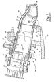
Fig. 1 is a partial cross-section of a known gas turbine combustor; -
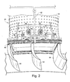
Fig. 2 is a top perspective, and partially schematic view of the interface between a combustor transition duct and a turbine first stage nozzle; -
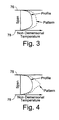
Fig. 3 is a diagrammatic illustration of average and peak temperature profiles at the exit end of a transition duct of a combustor that does not incorporate additional fuel nozzles in the transition duct as in an exemplary but non-limiting embodiment of the invention. -
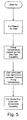
Fig. 4 is a diagrammatic illustration similar toFig. 3 but illustrating the average and peak temperature profiles for a transition duct that does incorporate additional nozzles in accordance with an exemplary but non-limiting embodiment; -
Fig. 5 is a flow diagram illustrating the various operating conditions of a turbine indicating the timing of the late lean fuel injection technique in accordance with an exemplary but non-limiting embodiment disclosed herein; and -
Fig. 6 is a schematic end view of the transition duct and nozzle vanes, illustrating the location of peak temperature regions relative to the duct wall and nozzle vanes in accordance with the exemplary but nonlimiting embodiment described herein. - With initial reference to
Fig. 1 , a known gas turbine 10 (partially shown) includes a compressor 12 (also partially shown), a plurality of can-annular-type combustors 14 (one shown), and a turbine section represented here by asingle nozzle blade 16. Although not specifically shown, the turbine is drivingly connected to the compressor 12 along a common axis, i.e., the rotor axis. The compressor 12 pressurizes inlet air which is then reverse flowed to thecombustor 14 where it is used to cool the combustor and to provide air to the combustion process. It will be appreciated, however, the invention is not limited to can-annular type combustors. - As noted above, a plurality of
combustors 14 are located in an annular array about the axis of the gas turbine. Atransition duct 18 connects the aft end of each combustor with the inlet end of the turbine to deliver the hot products of combustion to the turbine first stage. Ignition is achieved in thevarious combustors 14 by means of a spark initiating device in conjunction with crossfire tubes 22 (one shown) in the usual manner. - Each
combustor 14 includes a substantiallycylindrical combustor casing 24 which is secured to theturbine casing 26 by means ofbolts 28. The forward end of the combustor casing is closed by anend cover assembly 30 which includes supply tubes, manifolds and associated valves for feeding gaseous fuel, liquid fuel, air and water to the combustor as well understood in the art. Theend cover assembly 30 also supports a plurality (for example, three to six) "outer" fuel nozzle assemblies 32 (only one shown inFig. 1 for purposes of convenience and clarity), arranged in a circular array about a longitudinal axis of the combustor, and one center nozzle (not visible inFig. 1 ). - Within the
combustor casing 24, there is mounted, in substantially concentric relation thereto, a substantiallycylindrical flow sleeve 34 which connects at its aft end to theouter wall 36 of thetransition duct 18. Theflow sleeve 34 is connected at its forward end by means of aradial flange 35 to thecombustor casing 24 at abutt joint 37 where fore and aft sections of thecombustor casing 24 are joined. - Within the
flow sleeve 34, there is a concentrically-arrangedcombustor liner 38 defining acombustion chamber 39, and which is connected at its aft end with theinner wall 40 of thetransition duct 18. The forward end of thecombustor liner 38 is supported by a combustorliner cap assembly 42 which is, in turn, supported within thecombustor casing 24 by a plurality of struts and an associated mounting assembly (not shown in detail). - The
outer wall 36 of thetransition duct 18 and theflow sleeve 34 may be provided with an array ofapertures 44 to permit compressor discharge air to flow through theapertures 44 and into the annular space between theflow sleeve 34 andcombustor liner 38 where it reverses flow toward the upstream end of the combustor (as indicated by the flow arrows inFig. 1 ). This is a well known arrangement that needs no further discussion. - Turning to
Fig. 2 , a modifiedtransition duct 20 is attached to the first stage of the turbine section at the aft end of the duct, defined by a relatively rigidperipheral frame member 46 and additional attachment hardware indicated generally at 48. The transition duct frame and attachment hardware are generally known and form no part of this invention. The turbine first stage nozzle is represented inFig. 2 by a plurality of firststage nozzle vanes - In accordance with an exemplary but non-limiting embodiment, two or more late lean
fuel injection nozzles 56,58 (also referred to simply as "fuel injection nozzles") are mounted on the transition duct at itsaft end 20 proximate theattachment hardware 48 and therigid frame 46, and extending through the double-walled duct, i.e.,outer wall 36 andinner wall 40. Fuel is supplied to theinjection nozzles manifold 60 and asupply conduit 62 which extends to another manifold (not shown) surrounding the aft ends of the array of can-annular combustors. Thus, the surrounding manifold will supply fuel to thefuel injection nozzles branch inlets - Optionally, and without limitation on the invention described herein, the
fuel injection nozzles upper ends manifold 60. If desired,internal swirler devices nozzles transition duct 18. As will be understood by one of ordinary skill in the art, the size of theopen ends injection nozzles - As also apparent from
Fig. 2 , thefuel injection nozzles injection nozzle 56 is located circumferentially between thenozzle vanes injection nozzle 58 is located circumferentially between thenozzle vanes transition duct 20. For other turbine applications, there may be four nozzle vanes within the outlet profile of the transition duct and that case, there may be three late lean fuel injection nozzles, also placed circumferentially between respective adjacent vane pairs. - By locating the late lean
fuel injection nozzles transition duct 18, and in proper alignment the first stage nozzle vanes 50, 52 and 54, the average temperature profile of the combustor exit temperature may be maintained or even increased without exposing the hot gas path combustor components to peak temperatures. In other words, the late lean combustion occurs downstream of thecombustion chamber 39 which is normally at a higher temperature than the aft end of thetransition duct 18. In addition, the peak temperature regions produced by the late lean injection combustion are located away from the duct walls and circumferentially between the first stage nozzle vanes as depicted at P1 and P2 inFig. 6 . - Another advantage of the present invention with respect to maintenance of a temperature exit profile but with increased service life of hot gas path components can also be seen from a comparison of
Figs. 3 and 4 . InFig. 3 , the average temperature profile and peak temperature pattern are not perfectly symmetrical, indicating a so-called cold streak nearer one side of the transition duct side walls represented by thehorizontal lines fuel injection nozzles Fig. 4 . In other words, while the average exit temperature remains unchanged as betweenFigs. 3 and 4 , the peak temperature pattern is engineered away from the transitionduct side walls - In other words, the peak temperatures can be kept away from the metal parts, while the overall heat into to the turbine can be increased or adjusted to provide more uniform exit temperature profiles. This leads to a longer service life for the components and increased output efficiency for the turbine.
-
Fig. 5 illustrates in flowchart form, the various operating conditions of the turbine from start up to full-speed to full-load. More specifically after start up, the turbine is brought up to a full speed no-load condition, and subsequently to a firing temperature that is normally limited by hot gas path component durability. By using the late lean fuel injection in accordance with the embodiments described herein, the turbine firing temperature can be increased without negatively impacting on the hot gas path durability, and the turbine may be brought to a full-speed full-load condition with acceptable component durability.
Claims (10)
- A gas turbine combustor (10) comprising:a combustion chamber (39) defined by a combustor liner (38), said combustor liner having an upstream end cover (30) supporting one or more nozzles (32) arranged to supply fuel to the combustion chamber where the fuel mixes with air supplied from a compressor (12); a transition duct (18) connected between a downstream end of said combustor liner and a first stage turbine nozzle (50, 52, 54), said transition duct supplying gaseous products of combustion to said first stage turbine nozzle; and a plurality of fuel injection nozzles (56, 58) for introducing additional fuel and air for combustion into said transition duct (18) upstream of said first stage turbine nozzle, wherein each of said plurality of fuel injection nozzles is formed with an open end to draw air from surrounding compressor discharge air , characterized in that said plurality of fuel injection nozzles (56, 58) are arranged at an aft end (20) of said transition duct (18) and are located circumferentially between proximate vanes of said first stage turbine nozzle, and in that each of said plurality of fuel injection nozzles (56, 58) includes an internal swirler device (72,74) for mixing the compressor discharge air with fuel supplied to said plurality of fuel injection nozzles (56,58).
- The gas turbine combustor of claim 1, wherein said plurality of fuel injection nozzles (56, 58) are arranged to introduce additional fuel and air in a direction substantially perpendicular to flow of gaseous products of combustion in said transition duct (18).
- The gas turbine combustor of claim 2, wherein said plurality of fuel injection nozzles (56,58) comprise a pair of fuel injection nozzles arranged on either side of a longitudinal axis of said transition duct (18).
- The gas turbine combustor of any of the preceding claims, wherein said plurality of fuel injection nozzles (56, 58) comprise three fuel injection nozzles.
- The gas turbine combustor of any of the preceding claims, wherein said plurality of fuel injection nozzles (56, 58) are located to increase inlet temperature at the first stage turbine nozzle but to move higher peak temperatures away from surfaces of proximate turbine hot gas path components.
- The gas turbine combustor of any of the preceding claims, wherein fuel supplied to said plurality of fuel injection nozzles (56, 58) is introduced differentially such that more fuel is supplied to regions of relatively cooler combustion gas temperatures.
- A method of managing a combustor exit temperature profile comprising:(a) flowing combustion gases from a turbine combustion chamber (39) to a first stage turbine nozzle (50, 52, 54) via a transition duct (18) attached to one end to a combustor liner (38) at least partially defining said combustion chamber (39);(b) arranging a plurality of fuel injection nozzles (56, 58) remote from said combustion chamber (39); and(c) supplying an amount of fuel to said fuel injection nozzles sufficient to achieve a desired combustor exit temperatures profile,characterized in that step (b) is implemented by locating said plurality of fuel injection nozzles at an aft end (20) of said transition duct (18) and circumferentially between proximate first stage turbine nozzle vanes (50,52,54), wherein each of said plurality of fuel injection nozzles (56,58) draws compressor discharge air into an internal swirler (72,74) for mixing said fuel and said compressor discharge air within each of said plurality of fuel injection nozzles (56,58).
- The method of claim 7, wherein, during step (c) fuel is supplied in different amounts to each of said fuel injection nozzles (56, 58).
- The method of any of claims 7 to 8, wherein said plurality of fuel injection nozzles (56, 58) comprise one less than the number of first stage nozzle blades (50, 52, 54) that are at least partially exposed within an exit opening profile of said transition duct (18).
- The method of any of claims 7 to 9, wherein said plurality of fuel injection nozzles (56, 58) are arranged to introduce additional fuel in a direction substantially perpendicular to flow of gaseous products of combustion in said transition duct (18).
Applications Claiming Priority (1)
| Application Number | Priority Date | Filing Date | Title |
|---|---|---|---|
| US12/758,296 US8082739B2 (en) | 2010-04-12 | 2010-04-12 | Combustor exit temperature profile control via fuel staging and related method |
Publications (3)
| Publication Number | Publication Date |
|---|---|
| EP2375167A2 EP2375167A2 (en) | 2011-10-12 |
| EP2375167A3 EP2375167A3 (en) | 2012-05-30 |
| EP2375167B1 true EP2375167B1 (en) | 2015-06-24 |
Family
ID=44260276
Family Applications (1)
| Application Number | Title | Priority Date | Filing Date |
|---|---|---|---|
| EP11161667.8A Active EP2375167B1 (en) | 2010-04-12 | 2011-04-08 | Combustor exit temperature profile control via fuel staging and related method |
Country Status (4)
| Country | Link |
|---|---|
| US (1) | US8082739B2 (en) |
| EP (1) | EP2375167B1 (en) |
| JP (1) | JP5236769B2 (en) |
| CN (1) | CN102235670B (en) |
Families Citing this family (26)
| Publication number | Priority date | Publication date | Assignee | Title |
|---|---|---|---|---|
| JP5180807B2 (en) | 2008-12-24 | 2013-04-10 | 三菱重工業株式会社 | 1st-stage stationary blade cooling structure and gas turbine |
| US9267443B2 (en) | 2009-05-08 | 2016-02-23 | Gas Turbine Efficiency Sweden Ab | Automated tuning of gas turbine combustion systems |
| US9671797B2 (en) | 2009-05-08 | 2017-06-06 | Gas Turbine Efficiency Sweden Ab | Optimization of gas turbine combustion systems low load performance on simple cycle and heat recovery steam generator applications |
| US8437941B2 (en) | 2009-05-08 | 2013-05-07 | Gas Turbine Efficiency Sweden Ab | Automated tuning of gas turbine combustion systems |
| US9354618B2 (en) | 2009-05-08 | 2016-05-31 | Gas Turbine Efficiency Sweden Ab | Automated tuning of multiple fuel gas turbine combustion systems |
| JP5479058B2 (en) * | 2009-12-07 | 2014-04-23 | 三菱重工業株式会社 | Communication structure between combustor and turbine section, and gas turbine |
| US20130291548A1 (en) * | 2011-02-28 | 2013-11-07 | General Electric Company | Combustor mixing joint and methods of improving durability of a first stage bucket of a turbine |
| US8407892B2 (en) * | 2011-08-05 | 2013-04-02 | General Electric Company | Methods relating to integrating late lean injection into combustion turbine engines |
| RU2494312C1 (en) * | 2012-04-02 | 2013-09-27 | Федеральное государственное унитарное предприятие "Государственный космический научно-производственный центр имени М.В. Хруничева" | Packaged burner |
| US9133722B2 (en) * | 2012-04-30 | 2015-09-15 | General Electric Company | Transition duct with late injection in turbine system |
| US9551492B2 (en) | 2012-11-30 | 2017-01-24 | General Electric Company | Gas turbine engine system and an associated method thereof |
| US9435541B2 (en) * | 2013-03-15 | 2016-09-06 | General Electric Company | Systems and apparatus relating to downstream fuel and air injection in gas turbines |
| US9631812B2 (en) | 2013-03-18 | 2017-04-25 | General Electric Company | Support frame and method for assembly of a combustion module of a gas turbine |
| US9322556B2 (en) * | 2013-03-18 | 2016-04-26 | General Electric Company | Flow sleeve assembly for a combustion module of a gas turbine combustor |
| US9400114B2 (en) | 2013-03-18 | 2016-07-26 | General Electric Company | Combustor support assembly for mounting a combustion module of a gas turbine |
| US9316155B2 (en) | 2013-03-18 | 2016-04-19 | General Electric Company | System for providing fuel to a combustor |
| US10436445B2 (en) | 2013-03-18 | 2019-10-08 | General Electric Company | Assembly for controlling clearance between a liner and stationary nozzle within a gas turbine |
| US9383104B2 (en) | 2013-03-18 | 2016-07-05 | General Electric Company | Continuous combustion liner for a combustor of a gas turbine |
| US9316396B2 (en) | 2013-03-18 | 2016-04-19 | General Electric Company | Hot gas path duct for a combustor of a gas turbine |
| US9360217B2 (en) * | 2013-03-18 | 2016-06-07 | General Electric Company | Flow sleeve for a combustion module of a gas turbine |
| CN104776449A (en) * | 2015-01-23 | 2015-07-15 | 北京华清燃气轮机与煤气化联合循环工程技术有限公司 | Hot channel afterburning combustion chamber |
| US20160265782A1 (en) * | 2015-03-10 | 2016-09-15 | General Electric Company | Air shield for a fuel injector of a combustor |
| EP3124749B1 (en) * | 2015-07-28 | 2018-12-19 | Ansaldo Energia Switzerland AG | First stage turbine vane arrangement |
| US10823422B2 (en) | 2017-10-17 | 2020-11-03 | General Electric Company | Tangential bulk swirl air in a trapped vortex combustor for a gas turbine engine |
| US11371709B2 (en) | 2020-06-30 | 2022-06-28 | General Electric Company | Combustor air flow path |
| CN113123883B (en) * | 2021-04-02 | 2022-06-28 | 浙江省涡轮机械与推进系统研究院 | Turbine engine and self-starting method thereof |
Family Cites Families (27)
| Publication number | Priority date | Publication date | Assignee | Title |
|---|---|---|---|---|
| US2520967A (en) * | 1948-01-16 | 1950-09-05 | Heinz E Schmitt | Turbojet engine with afterburner and fuel control system therefor |
| US3701255A (en) * | 1970-10-26 | 1972-10-31 | United Aircraft Corp | Shortened afterburner construction for turbine engine |
| US5000004A (en) * | 1988-08-16 | 1991-03-19 | Kabushiki Kaisha Toshiba | Gas turbine combustor |
| US5373694A (en) | 1992-11-17 | 1994-12-20 | United Technologies Corporation | Combustor seal and support |
| US5394688A (en) * | 1993-10-27 | 1995-03-07 | Westinghouse Electric Corporation | Gas turbine combustor swirl vane arrangement |
| US5454221A (en) | 1994-03-14 | 1995-10-03 | General Electric Company | Dilution flow sleeve for reducing emissions in a gas turbine combustor |
| US5974781A (en) * | 1995-12-26 | 1999-11-02 | General Electric Company | Hybrid can-annular combustor for axial staging in low NOx combustors |
| US6047550A (en) * | 1996-05-02 | 2000-04-11 | General Electric Co. | Premixing dry low NOx emissions combustor with lean direct injection of gas fuel |
| JP3063001B1 (en) * | 1998-12-28 | 2000-07-12 | 川崎重工業株式会社 | Combustion method and combustion apparatus |
| US6405536B1 (en) | 2000-03-27 | 2002-06-18 | Wu-Chi Ho | Gas turbine combustor burning LBTU fuel gas |
| US20030024234A1 (en) * | 2001-08-02 | 2003-02-06 | Siemens Westinghouse Power Corporation | Secondary combustor for low NOx gas combustion turbine |
| US7137613B2 (en) | 2002-02-28 | 2006-11-21 | Jansen's Aircraft Systems Controls, Inc. | Pattern factor control valve |
| US6868676B1 (en) * | 2002-12-20 | 2005-03-22 | General Electric Company | Turbine containing system and an injector therefor |
| US7000400B2 (en) | 2004-03-17 | 2006-02-21 | Honeywell International, Inc. | Temperature variance reduction using variable penetration dilution jets |
| US7373772B2 (en) | 2004-03-17 | 2008-05-20 | General Electric Company | Turbine combustor transition piece having dilution holes |
| JP4400314B2 (en) * | 2004-06-02 | 2010-01-20 | 株式会社日立製作所 | Gas turbine combustor and fuel supply method for gas turbine combustor |
| JP4670035B2 (en) * | 2004-06-25 | 2011-04-13 | 独立行政法人 宇宙航空研究開発機構 | Gas turbine combustor |
| US7000396B1 (en) | 2004-09-02 | 2006-02-21 | General Electric Company | Concentric fixed dilution and variable bypass air injection for a combustor |
| US7421843B2 (en) | 2005-01-15 | 2008-09-09 | Siemens Power Generation, Inc. | Catalytic combustor having fuel flow control responsive to measured combustion parameters |
| CN100570216C (en) * | 2005-06-24 | 2009-12-16 | 株式会社日立制作所 | The cooling means of pulverizing jet, gas turbine burner, pulverizing jet and the remodeling method of pulverizing jet |
| US20100018211A1 (en) * | 2008-07-23 | 2010-01-28 | General Electric Company | Gas turbine transition piece having dilution holes |
| US7886545B2 (en) * | 2007-04-27 | 2011-02-15 | General Electric Company | Methods and systems to facilitate reducing NOx emissions in combustion systems |
| US8387398B2 (en) * | 2007-09-14 | 2013-03-05 | Siemens Energy, Inc. | Apparatus and method for controlling the secondary injection of fuel |
| US7665309B2 (en) * | 2007-09-14 | 2010-02-23 | Siemens Energy, Inc. | Secondary fuel delivery system |
| US8047008B2 (en) * | 2008-03-31 | 2011-11-01 | General Electric Company | Replaceable orifice for combustion tuning and related method |
| US8707707B2 (en) * | 2009-01-07 | 2014-04-29 | General Electric Company | Late lean injection fuel staging configurations |
| US8689559B2 (en) * | 2009-03-30 | 2014-04-08 | General Electric Company | Secondary combustion system for reducing the level of emissions generated by a turbomachine |
-
2010
- 2010-04-12 US US12/758,296 patent/US8082739B2/en active Active
-
2011
- 2011-04-06 JP JP2011084134A patent/JP5236769B2/en active Active
- 2011-04-08 EP EP11161667.8A patent/EP2375167B1/en active Active
- 2011-04-12 CN CN201110099786.3A patent/CN102235670B/en active Active
Also Published As
| Publication number | Publication date |
|---|---|
| US20110247314A1 (en) | 2011-10-13 |
| EP2375167A3 (en) | 2012-05-30 |
| CN102235670A (en) | 2011-11-09 |
| US8082739B2 (en) | 2011-12-27 |
| JP5236769B2 (en) | 2013-07-17 |
| JP2011220673A (en) | 2011-11-04 |
| CN102235670B (en) | 2015-11-25 |
| EP2375167A2 (en) | 2011-10-12 |
Similar Documents
| Publication | Publication Date | Title |
|---|---|---|
| EP2375167B1 (en) | Combustor exit temperature profile control via fuel staging and related method | |
| CN105371300B (en) | Downstream nozzle and late lean injector for a combustor of a gas turbine engine | |
| US9835333B2 (en) | System and method for utilizing cooling air within a combustor | |
| CN108019777B (en) | Small hybrid fuel nozzle assembly for multi-point centerbody injector | |
| CN108019775B (en) | Compact hybrid fuel nozzle assembly with mixing sleeve | |
| US8528839B2 (en) | Combustor nozzle and method for fabricating the combustor nozzle | |
| US10690350B2 (en) | Combustor with axially staged fuel injection | |
| EP3220047B1 (en) | Gas turbine flow sleeve mounting | |
| US20190024895A1 (en) | Combustor dilution structure for gas turbine engine | |
| US10508811B2 (en) | Circumferential fuel shifting and biasing in an axial staged combustor for a gas turbine engine | |
| AU2019271909B2 (en) | Premixed fuel nozzle | |
| US11566790B1 (en) | Methods of operating a turbomachine combustor on hydrogen | |
| EP3875856B1 (en) | Integrated combustor nozzle with fluid mixing assembly | |
| US11156362B2 (en) | Combustor with axially staged fuel injection | |
| US20180187563A1 (en) | Gas turbine transition duct with late lean injection having reduced combustion residence time | |
| JP2017116250A (en) | Fuel injectors and staged fuel injection systems in gas turbines | |
| JP6001854B2 (en) | Combustor assembly for turbine engine and method for assembling the same | |
| US20120031099A1 (en) | Combustor assembly for use in a turbine engine and methods of assembling same | |
| CN113864818A (en) | Combustor air flow path | |
| US20180340689A1 (en) | Low Profile Axially Staged Fuel Injector | |
| US10344978B2 (en) | Combustion liner cooling | |
| US20080148738A1 (en) | Combustor construction | |
| US20180163968A1 (en) | Fuel Nozzle Assembly with Inlet Flow Conditioner | |
| EP4067746B1 (en) | Combustor having a wake energizer | |
| US10935235B2 (en) | Non-planar combustor liner panel for a gas turbine engine combustor |
Legal Events
| Date | Code | Title | Description |
|---|---|---|---|
| PUAI | Public reference made under article 153(3) epc to a published international application that has entered the european phase |
Free format text: ORIGINAL CODE: 0009012 |
|
| AK | Designated contracting states |
Kind code of ref document: A2 Designated state(s): AL AT BE BG CH CY CZ DE DK EE ES FI FR GB GR HR HU IE IS IT LI LT LU LV MC MK MT NL NO PL PT RO RS SE SI SK SM TR |
|
| AX | Request for extension of the european patent |
Extension state: BA ME |
|
| PUAL | Search report despatched |
Free format text: ORIGINAL CODE: 0009013 |
|
| AK | Designated contracting states |
Kind code of ref document: A3 Designated state(s): AL AT BE BG CH CY CZ DE DK EE ES FI FR GB GR HR HU IE IS IT LI LT LU LV MC MK MT NL NO PL PT RO RS SE SI SK SM TR |
|
| AX | Request for extension of the european patent |
Extension state: BA ME |
|
| RIC1 | Information provided on ipc code assigned before grant |
Ipc: F23R 3/34 20060101AFI20120425BHEP |
|
| 17P | Request for examination filed |
Effective date: 20121130 |
|
| GRAP | Despatch of communication of intention to grant a patent |
Free format text: ORIGINAL CODE: EPIDOSNIGR1 |
|
| INTG | Intention to grant announced |
Effective date: 20150212 |
|
| GRAS | Grant fee paid |
Free format text: ORIGINAL CODE: EPIDOSNIGR3 |
|
| GRAA | (expected) grant |
Free format text: ORIGINAL CODE: 0009210 |
|
| AK | Designated contracting states |
Kind code of ref document: B1 Designated state(s): AL AT BE BG CH CY CZ DE DK EE ES FI FR GB GR HR HU IE IS IT LI LT LU LV MC MK MT NL NO PL PT RO RS SE SI SK SM TR |
|
| REG | Reference to a national code |
Ref country code: GB Ref legal event code: FG4D |
|
| REG | Reference to a national code |
Ref country code: CH Ref legal event code: EP |
|
| REG | Reference to a national code |
Ref country code: AT Ref legal event code: REF Ref document number: 733074 Country of ref document: AT Kind code of ref document: T Effective date: 20150715 |
|
| REG | Reference to a national code |
Ref country code: IE Ref legal event code: FG4D |
|
| REG | Reference to a national code |
Ref country code: DE Ref legal event code: R096 Ref document number: 602011017300 Country of ref document: DE |
|
| PG25 | Lapsed in a contracting state [announced via postgrant information from national office to epo] |
Ref country code: NO Free format text: LAPSE BECAUSE OF FAILURE TO SUBMIT A TRANSLATION OF THE DESCRIPTION OR TO PAY THE FEE WITHIN THE PRESCRIBED TIME-LIMIT Effective date: 20150924 Ref country code: FI Free format text: LAPSE BECAUSE OF FAILURE TO SUBMIT A TRANSLATION OF THE DESCRIPTION OR TO PAY THE FEE WITHIN THE PRESCRIBED TIME-LIMIT Effective date: 20150624 Ref country code: HR Free format text: LAPSE BECAUSE OF FAILURE TO SUBMIT A TRANSLATION OF THE DESCRIPTION OR TO PAY THE FEE WITHIN THE PRESCRIBED TIME-LIMIT Effective date: 20150624 Ref country code: LT Free format text: LAPSE BECAUSE OF FAILURE TO SUBMIT A TRANSLATION OF THE DESCRIPTION OR TO PAY THE FEE WITHIN THE PRESCRIBED TIME-LIMIT Effective date: 20150624 |
|
| REG | Reference to a national code |
Ref country code: AT Ref legal event code: MK05 Ref document number: 733074 Country of ref document: AT Kind code of ref document: T Effective date: 20150624 |
|
| REG | Reference to a national code |
Ref country code: LT Ref legal event code: MG4D |
|
| PG25 | Lapsed in a contracting state [announced via postgrant information from national office to epo] |
Ref country code: LV Free format text: LAPSE BECAUSE OF FAILURE TO SUBMIT A TRANSLATION OF THE DESCRIPTION OR TO PAY THE FEE WITHIN THE PRESCRIBED TIME-LIMIT Effective date: 20150624 Ref country code: GR Free format text: LAPSE BECAUSE OF FAILURE TO SUBMIT A TRANSLATION OF THE DESCRIPTION OR TO PAY THE FEE WITHIN THE PRESCRIBED TIME-LIMIT Effective date: 20150925 Ref country code: RS Free format text: LAPSE BECAUSE OF FAILURE TO SUBMIT A TRANSLATION OF THE DESCRIPTION OR TO PAY THE FEE WITHIN THE PRESCRIBED TIME-LIMIT Effective date: 20150624 Ref country code: BG Free format text: LAPSE BECAUSE OF FAILURE TO SUBMIT A TRANSLATION OF THE DESCRIPTION OR TO PAY THE FEE WITHIN THE PRESCRIBED TIME-LIMIT Effective date: 20150924 |
|
| REG | Reference to a national code |
Ref country code: NL Ref legal event code: MP Effective date: 20150624 |
|
| PG25 | Lapsed in a contracting state [announced via postgrant information from national office to epo] |
Ref country code: EE Free format text: LAPSE BECAUSE OF FAILURE TO SUBMIT A TRANSLATION OF THE DESCRIPTION OR TO PAY THE FEE WITHIN THE PRESCRIBED TIME-LIMIT Effective date: 20150624 |
|
| PG25 | Lapsed in a contracting state [announced via postgrant information from national office to epo] |
Ref country code: ES Free format text: LAPSE BECAUSE OF FAILURE TO SUBMIT A TRANSLATION OF THE DESCRIPTION OR TO PAY THE FEE WITHIN THE PRESCRIBED TIME-LIMIT Effective date: 20150624 Ref country code: SK Free format text: LAPSE BECAUSE OF FAILURE TO SUBMIT A TRANSLATION OF THE DESCRIPTION OR TO PAY THE FEE WITHIN THE PRESCRIBED TIME-LIMIT Effective date: 20150624 Ref country code: RO Free format text: LAPSE BECAUSE OF NON-PAYMENT OF DUE FEES Effective date: 20150624 Ref country code: AT Free format text: LAPSE BECAUSE OF FAILURE TO SUBMIT A TRANSLATION OF THE DESCRIPTION OR TO PAY THE FEE WITHIN THE PRESCRIBED TIME-LIMIT Effective date: 20150624 Ref country code: PL Free format text: LAPSE BECAUSE OF FAILURE TO SUBMIT A TRANSLATION OF THE DESCRIPTION OR TO PAY THE FEE WITHIN THE PRESCRIBED TIME-LIMIT Effective date: 20150624 Ref country code: IS Free format text: LAPSE BECAUSE OF FAILURE TO SUBMIT A TRANSLATION OF THE DESCRIPTION OR TO PAY THE FEE WITHIN THE PRESCRIBED TIME-LIMIT Effective date: 20151024 Ref country code: CZ Free format text: LAPSE BECAUSE OF FAILURE TO SUBMIT A TRANSLATION OF THE DESCRIPTION OR TO PAY THE FEE WITHIN THE PRESCRIBED TIME-LIMIT Effective date: 20150624 Ref country code: PT Free format text: LAPSE BECAUSE OF FAILURE TO SUBMIT A TRANSLATION OF THE DESCRIPTION OR TO PAY THE FEE WITHIN THE PRESCRIBED TIME-LIMIT Effective date: 20151026 |
|
| REG | Reference to a national code |
Ref country code: DE Ref legal event code: R097 Ref document number: 602011017300 Country of ref document: DE |
|
| PG25 | Lapsed in a contracting state [announced via postgrant information from national office to epo] |
Ref country code: DK Free format text: LAPSE BECAUSE OF FAILURE TO SUBMIT A TRANSLATION OF THE DESCRIPTION OR TO PAY THE FEE WITHIN THE PRESCRIBED TIME-LIMIT Effective date: 20150624 Ref country code: IT Free format text: LAPSE BECAUSE OF FAILURE TO SUBMIT A TRANSLATION OF THE DESCRIPTION OR TO PAY THE FEE WITHIN THE PRESCRIBED TIME-LIMIT Effective date: 20150624 |
|
| PLBE | No opposition filed within time limit |
Free format text: ORIGINAL CODE: 0009261 |
|
| STAA | Information on the status of an ep patent application or granted ep patent |
Free format text: STATUS: NO OPPOSITION FILED WITHIN TIME LIMIT |
|
| 26N | No opposition filed |
Effective date: 20160329 |
|
| PG25 | Lapsed in a contracting state [announced via postgrant information from national office to epo] |
Ref country code: BE Free format text: LAPSE BECAUSE OF NON-PAYMENT OF DUE FEES Effective date: 20160430 Ref country code: SI Free format text: LAPSE BECAUSE OF FAILURE TO SUBMIT A TRANSLATION OF THE DESCRIPTION OR TO PAY THE FEE WITHIN THE PRESCRIBED TIME-LIMIT Effective date: 20150624 |
|
| REG | Reference to a national code |
Ref country code: CH Ref legal event code: PL |
|
| GBPC | Gb: european patent ceased through non-payment of renewal fee |
Effective date: 20160408 |
|
| PG25 | Lapsed in a contracting state [announced via postgrant information from national office to epo] |
Ref country code: BE Free format text: LAPSE BECAUSE OF FAILURE TO SUBMIT A TRANSLATION OF THE DESCRIPTION OR TO PAY THE FEE WITHIN THE PRESCRIBED TIME-LIMIT Effective date: 20150624 Ref country code: LU Free format text: LAPSE BECAUSE OF FAILURE TO SUBMIT A TRANSLATION OF THE DESCRIPTION OR TO PAY THE FEE WITHIN THE PRESCRIBED TIME-LIMIT Effective date: 20160408 |
|
| REG | Reference to a national code |
Ref country code: IE Ref legal event code: MM4A |
|
| REG | Reference to a national code |
Ref country code: FR Ref legal event code: ST Effective date: 20161230 |
|
| PG25 | Lapsed in a contracting state [announced via postgrant information from national office to epo] |
Ref country code: GB Free format text: LAPSE BECAUSE OF NON-PAYMENT OF DUE FEES Effective date: 20160408 Ref country code: LI Free format text: LAPSE BECAUSE OF NON-PAYMENT OF DUE FEES Effective date: 20160430 Ref country code: FR Free format text: LAPSE BECAUSE OF NON-PAYMENT OF DUE FEES Effective date: 20160502 Ref country code: CH Free format text: LAPSE BECAUSE OF NON-PAYMENT OF DUE FEES Effective date: 20160430 |
|
| PG25 | Lapsed in a contracting state [announced via postgrant information from national office to epo] |
Ref country code: IE Free format text: LAPSE BECAUSE OF NON-PAYMENT OF DUE FEES Effective date: 20160408 |
|
| PG25 | Lapsed in a contracting state [announced via postgrant information from national office to epo] |
Ref country code: NL Free format text: LAPSE BECAUSE OF FAILURE TO SUBMIT A TRANSLATION OF THE DESCRIPTION OR TO PAY THE FEE WITHIN THE PRESCRIBED TIME-LIMIT Effective date: 20150624 Ref country code: SE Free format text: LAPSE BECAUSE OF FAILURE TO SUBMIT A TRANSLATION OF THE DESCRIPTION OR TO PAY THE FEE WITHIN THE PRESCRIBED TIME-LIMIT Effective date: 20150624 |
|
| PG25 | Lapsed in a contracting state [announced via postgrant information from national office to epo] |
Ref country code: HU Free format text: LAPSE BECAUSE OF FAILURE TO SUBMIT A TRANSLATION OF THE DESCRIPTION OR TO PAY THE FEE WITHIN THE PRESCRIBED TIME-LIMIT; INVALID AB INITIO Effective date: 20110408 Ref country code: SM Free format text: LAPSE BECAUSE OF FAILURE TO SUBMIT A TRANSLATION OF THE DESCRIPTION OR TO PAY THE FEE WITHIN THE PRESCRIBED TIME-LIMIT Effective date: 20150624 Ref country code: CY Free format text: LAPSE BECAUSE OF FAILURE TO SUBMIT A TRANSLATION OF THE DESCRIPTION OR TO PAY THE FEE WITHIN THE PRESCRIBED TIME-LIMIT Effective date: 20150624 |
|
| PG25 | Lapsed in a contracting state [announced via postgrant information from national office to epo] |
Ref country code: MT Free format text: LAPSE BECAUSE OF NON-PAYMENT OF DUE FEES Effective date: 20160430 Ref country code: MC Free format text: LAPSE BECAUSE OF FAILURE TO SUBMIT A TRANSLATION OF THE DESCRIPTION OR TO PAY THE FEE WITHIN THE PRESCRIBED TIME-LIMIT Effective date: 20150624 Ref country code: TR Free format text: LAPSE BECAUSE OF FAILURE TO SUBMIT A TRANSLATION OF THE DESCRIPTION OR TO PAY THE FEE WITHIN THE PRESCRIBED TIME-LIMIT Effective date: 20150624 Ref country code: MK Free format text: LAPSE BECAUSE OF FAILURE TO SUBMIT A TRANSLATION OF THE DESCRIPTION OR TO PAY THE FEE WITHIN THE PRESCRIBED TIME-LIMIT Effective date: 20150624 |
|
| PG25 | Lapsed in a contracting state [announced via postgrant information from national office to epo] |
Ref country code: AL Free format text: LAPSE BECAUSE OF FAILURE TO SUBMIT A TRANSLATION OF THE DESCRIPTION OR TO PAY THE FEE WITHIN THE PRESCRIBED TIME-LIMIT Effective date: 20150624 |
|
| REG | Reference to a national code |
Ref country code: DE Ref legal event code: R081 Ref document number: 602011017300 Country of ref document: DE Owner name: GENERAL ELECTRIC TECHNOLOGY GMBH, CH Free format text: FORMER OWNER: GENERAL ELECTRIC CO., SCHENECTADY, N.Y., US |
|
| PGFP | Annual fee paid to national office [announced via postgrant information from national office to epo] |
Ref country code: DE Payment date: 20240320 Year of fee payment: 14 |