EP2574811A2 - Hydraulic clutch - Google Patents
Hydraulic clutch Download PDFInfo
- Publication number
- EP2574811A2 EP2574811A2 EP20120186310 EP12186310A EP2574811A2 EP 2574811 A2 EP2574811 A2 EP 2574811A2 EP 20120186310 EP20120186310 EP 20120186310 EP 12186310 A EP12186310 A EP 12186310A EP 2574811 A2 EP2574811 A2 EP 2574811A2
- Authority
- EP
- European Patent Office
- Prior art keywords
- hub
- hydraulic
- clutch
- hydraulic chamber
- toroidal
- Prior art date
- Legal status (The legal status is an assumption and is not a legal conclusion. Google has not performed a legal analysis and makes no representation as to the accuracy of the status listed.)
- Withdrawn
Links
Images

Classifications
-
- F—MECHANICAL ENGINEERING; LIGHTING; HEATING; WEAPONS; BLASTING
- F16—ENGINEERING ELEMENTS AND UNITS; GENERAL MEASURES FOR PRODUCING AND MAINTAINING EFFECTIVE FUNCTIONING OF MACHINES OR INSTALLATIONS; THERMAL INSULATION IN GENERAL
- F16D—COUPLINGS FOR TRANSMITTING ROTATION; CLUTCHES; BRAKES
- F16D25/00—Fluid-actuated clutches
- F16D25/06—Fluid-actuated clutches in which the fluid actuates a piston incorporated in, i.e. rotating with the clutch
- F16D25/062—Fluid-actuated clutches in which the fluid actuates a piston incorporated in, i.e. rotating with the clutch the clutch having friction surfaces
- F16D25/063—Fluid-actuated clutches in which the fluid actuates a piston incorporated in, i.e. rotating with the clutch the clutch having friction surfaces with clutch members exclusively moving axially
- F16D25/0635—Fluid-actuated clutches in which the fluid actuates a piston incorporated in, i.e. rotating with the clutch the clutch having friction surfaces with clutch members exclusively moving axially with flat friction surfaces, e.g. discs
- F16D25/0638—Fluid-actuated clutches in which the fluid actuates a piston incorporated in, i.e. rotating with the clutch the clutch having friction surfaces with clutch members exclusively moving axially with flat friction surfaces, e.g. discs with more than two discs, e.g. multiple lamellae
-
- F—MECHANICAL ENGINEERING; LIGHTING; HEATING; WEAPONS; BLASTING
- F16—ENGINEERING ELEMENTS AND UNITS; GENERAL MEASURES FOR PRODUCING AND MAINTAINING EFFECTIVE FUNCTIONING OF MACHINES OR INSTALLATIONS; THERMAL INSULATION IN GENERAL
- F16D—COUPLINGS FOR TRANSMITTING ROTATION; CLUTCHES; BRAKES
- F16D25/00—Fluid-actuated clutches
- F16D25/12—Details not specific to one of the before-mentioned types
- F16D25/123—Details not specific to one of the before-mentioned types in view of cooling and lubrication
-
- F—MECHANICAL ENGINEERING; LIGHTING; HEATING; WEAPONS; BLASTING
- F16—ENGINEERING ELEMENTS AND UNITS; GENERAL MEASURES FOR PRODUCING AND MAINTAINING EFFECTIVE FUNCTIONING OF MACHINES OR INSTALLATIONS; THERMAL INSULATION IN GENERAL
- F16D—COUPLINGS FOR TRANSMITTING ROTATION; CLUTCHES; BRAKES
- F16D48/00—External control of clutches
- F16D48/02—Control by fluid pressure
- F16D2048/0212—Details of pistons for primary or secondary cylinders especially adapted for fluid control
Definitions
- the present invention is related to hydraulic clutches, and more particularly, exemplary embodiments of the present invention are related to hydraulic clutches comprising hydraulic balance chambers.
- a hydraulic clutch apparatus includes a first hub, wherein the first hub includes a plurality of frictional clutch discs arranged therein, and a second hub arranged within the first hub and proximate the plurality of frictional clutch discs, wherein the second hub includes a first toroidal hydraulic chamber configured to depress the plurality of frictional clutch discs and a second toroidal hydraulic chamber opposing the first toroidal hydraulic chamber.
- a hydraulic clutch apparatus includes an output portion, a first hub in mechanical communication with the output portion, a second hub in mechanical communication with the first hub through a plurality of frictional clutch discs, and an input portion in mechanical communication with the second hub.
- the second hub includes a first hydraulic cavity configured to expand and depress the plurality of frictional clutch discs and the second hub further includes a second hydraulic cavity in mechanical communication with the first hydraulic cavity which is configured to restrict expansion of the first hydraulic cavity in response to rotation of the second hub.
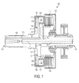
- FIG. 1 is a cross sectional view of a hydraulic clutch, according to an exemplary embodiment.
- FIG. 2 is an expanded cross sectional view of the hydraulic clutch of FIG. 1 .
- a hydraulic clutch which simplifies clutch application in high-speed rotating devices.
- the clutch includes a hydraulic balancing chamber opposing a conventional clutch application chamber.
- the hydraulic balancing chamber is in mechanical and fluid communication with the application chamber.
- the inner radius of the hydraulic balancing chamber is sized to produce an axial force sufficient to retract a clutch application piston, thereby forcing the application chamber fluid to sump through an associated hydraulic circuit.
- the hydraulic balancing chamber allows hydraulic release of an applied clutch without costly dumping of fluid to circumvent centrifugal pressure.
- the technical effects and benefits of the invention include increased reliability, lower cost, and enhanced controllability of engagement events for the clutch due to reduction in the effects of centrifugal forces within the clutch.
- the clutch 100 is configured to engage or disengage rotational torque provided from an input portion 111 to an output portion 112 and transfer rotational energy from the input portion 111 to the output portion 112 through a plurality of clutch discs 110.
- the axis of rotation of the clutch 100 is herein referred to and labeled as Z'.
- the clutch 100 includes a first hub 101 arranged about a second hub 102.
- Each of the first hub 101 and second hub 102 may be rotationally symmetric about the Z' axis (i.e., central axis).
- the second hub 102 may be configured to depress the plurality of clutch discs 110 arranged within the first hub 101 so as to engage the clutch 100.
- the clutch 100 may include a plurality of hydraulic circuits arranged therein to enable depressing the plurality of clutch discs 110.
- the plurality of clutch discs 110 may be annular, frictional clutch discs of any suitable material and form.
- the plurality of clutch discs 110 may be wet clutch discs configured to receive oil or fluid for cooling through hydraulic circuit 103 supplied through fluid reservoir 104.
- the clutch 100 includes a primary or application chamber 106.
- the application chamber 106 is a first toroidal hydraulic chamber within the second hub 102 defined by interior space of the hub 102 and annular wall 114.
- Annular wall 114 is a protrusion from a main body 116 of the clutch 100, and provides support for the second hub 102.
- the clutch 100 further includes hydraulic application circuit 115 in fluid communication with the application chamber 106. As illustrated, hydraulic application circuit 115 may transfer hydraulic fluid through main body 116 to fill the application chamber 106. Upon receiving hydraulic fluid, increase in pressure within the application chamber 106 causes the second hub 102 to slide upon annular wall 114 thereby depressing the plurality of clutch discs 110 against the interior of hub 101. Thus, the combination of hydraulic circuit 115 and application chamber 106 allows application of the clutch 100.
- the balance chamber 109 is a second toroidal hydraulic chamber within the second hub 102 defined by interior space of the hub 102, annular wall 114, annular wall 113, and annular wall 117.
- Annular wall 117 is a protrusion from main body 116.
- Annular wall 113 is fixedly attached to second hub 102 and is configured to slide upon annular support wall 117.
- the balance chamber 109 is configured to receive hydraulic fluid through passage 108. Hydraulic fluid is provided to the balance chamber 109 from supply chamber 107. Finally, hydraulic fluid is provided to supply chamber 107 from hydraulic circuit 105. Upon receiving hydraulic fluid, increase in pressure within the balance chamber 109 restricts the expansive forces of chamber 106, thereby serving to mechanically "balance" the hydraulic system.
- a relative size and radial position of each of the application chamber 106 and balance chamber 109 determine an overall balance to centrifugal forces within the clutch 100.
- a central axis of the main body is collinear with a central axis of the first hub and a central axis of the second hub as shown in FIG. 2 denoted as Z'.
- FIG. 2 the relative size and position the application chamber 106 and balance chamber 109 are illustrated in detail. As illustrated, all values are determined through the radial distance from the axis Z'.
- Ro is the radial distance to an outer wall of the hub 102.
- Ri1 is the radial distance to an inner wall of the hub 102.
- Ri2 is the radial spill distance to the fluid passage 108.
- Rs is the radial distance to the supply chamber 107. Accordingly, the average centrifugal pressure apparent for any speed of revolution of the clutch 100 may be easily calculated through these radial distances.
- the average centrifugal pressure of the application chamber 106 may be calculated with Equation 1, provided below: C * RPM / 100 2 * Ro 4 / 2 - Ri ⁇ 1 4 / 2 - Rs 2 * Ro 2 + Rs 2 * Ri ⁇ 1 2 / pi * Ro 2 - Ri ⁇ 1 2
- Equation 1 RPM denotes the revolutions per minute of the entire clutch assembly 100, pi denotes the constant denoting the ratio of a circular circumference versus diameter, and C denotes a constant value or corrective value.
- the average centrifugal pressure of the balance chamber 109 may be calculated with Equation 2, provided below: C * RPM / 100 2 * Ro 4 / 2 - Ri ⁇ 2 4 / 2 - Rs 2 * Ro 2 + Rs 2 * Ri ⁇ 2 2 / pi * Ro 2 - Ri ⁇ 2 2
Landscapes
- Engineering & Computer Science (AREA)
- General Engineering & Computer Science (AREA)
- Mechanical Engineering (AREA)
- Hydraulic Clutches, Magnetic Clutches, Fluid Clutches, And Fluid Joints (AREA)
Abstract
Description
- The present invention is related to hydraulic clutches, and more particularly, exemplary embodiments of the present invention are related to hydraulic clutches comprising hydraulic balance chambers.
- High-speed, hydraulically actuated clutches generate large centrifugal pressures. The centrifugal pressure, operating on a clamping piston, generates clamp loads in excess of forces provided by most mechanical springs designed to release a clutch. Therefore, these clamp loads must be overcome to effectively release an applied clutch. Conventionally, a costly mechanical dump valve is implemented to circumvent the clamp loads and allow springs to retract an applied clutch. This results in additional time and fluid necessary to refill a hydraulic clutch application chamber and an associated hydraulic circuit for subsequent clutch application.
- According to an exemplary embodiment of the present invention, a hydraulic clutch apparatus includes a first hub, wherein the first hub includes a plurality of frictional clutch discs arranged therein, and a second hub arranged within the first hub and proximate the plurality of frictional clutch discs, wherein the second hub includes a first toroidal hydraulic chamber configured to depress the plurality of frictional clutch discs and a second toroidal hydraulic chamber opposing the first toroidal hydraulic chamber.
- According to another exemplary embodiment of the present invention, a hydraulic clutch apparatus includes an output portion, a first hub in mechanical communication with the output portion, a second hub in mechanical communication with the first hub through a plurality of frictional clutch discs, and an input portion in mechanical communication with the second hub. According to the embodiment, the second hub includes a first hydraulic cavity configured to expand and depress the plurality of frictional clutch discs and the second hub further includes a second hydraulic cavity in mechanical communication with the first hydraulic cavity which is configured to restrict expansion of the first hydraulic cavity in response to rotation of the second hub.
- The subject matter which is regarded as the invention is particularly pointed out and distinctly claimed in the claims at the conclusion of the specification. The foregoing and other features, and advantages of the invention are apparent from the following detailed description taken in conjunction with the accompanying drawings in which:
-
FIG. 1 is a cross sectional view of a hydraulic clutch, according to an exemplary embodiment; and -
FIG. 2 is an expanded cross sectional view of the hydraulic clutch ofFIG. 1 . - According to an embodiment of the present invention, a hydraulic clutch is provided which simplifies clutch application in high-speed rotating devices. The clutch includes a hydraulic balancing chamber opposing a conventional clutch application chamber. The hydraulic balancing chamber is in mechanical and fluid communication with the application chamber. The inner radius of the hydraulic balancing chamber is sized to produce an axial force sufficient to retract a clutch application piston, thereby forcing the application chamber fluid to sump through an associated hydraulic circuit. Thus, the hydraulic balancing chamber allows hydraulic release of an applied clutch without costly dumping of fluid to circumvent centrifugal pressure. The technical effects and benefits of the invention include increased reliability, lower cost, and enhanced controllability of engagement events for the clutch due to reduction in the effects of centrifugal forces within the clutch.
- Turning to
FIGS. 1 and2 , cross sectional views of a hydraulic clutch are provided. Theclutch 100 is configured to engage or disengage rotational torque provided from aninput portion 111 to anoutput portion 112 and transfer rotational energy from theinput portion 111 to theoutput portion 112 through a plurality ofclutch discs 110. The axis of rotation of theclutch 100 is herein referred to and labeled as Z'. As illustrated, theclutch 100 includes afirst hub 101 arranged about asecond hub 102. Each of thefirst hub 101 andsecond hub 102 may be rotationally symmetric about the Z' axis (i.e., central axis). - The
second hub 102 may be configured to depress the plurality ofclutch discs 110 arranged within thefirst hub 101 so as to engage theclutch 100. Theclutch 100 may include a plurality of hydraulic circuits arranged therein to enable depressing the plurality ofclutch discs 110. The plurality ofclutch discs 110 may be annular, frictional clutch discs of any suitable material and form. The plurality ofclutch discs 110 may be wet clutch discs configured to receive oil or fluid for cooling throughhydraulic circuit 103 supplied throughfluid reservoir 104. - The
clutch 100 includes a primary orapplication chamber 106. Theapplication chamber 106 is a first toroidal hydraulic chamber within thesecond hub 102 defined by interior space of thehub 102 andannular wall 114.Annular wall 114 is a protrusion from amain body 116 of theclutch 100, and provides support for thesecond hub 102. Theclutch 100 further includeshydraulic application circuit 115 in fluid communication with theapplication chamber 106. As illustrated,hydraulic application circuit 115 may transfer hydraulic fluid throughmain body 116 to fill theapplication chamber 106. Upon receiving hydraulic fluid, increase in pressure within theapplication chamber 106 causes thesecond hub 102 to slide uponannular wall 114 thereby depressing the plurality ofclutch discs 110 against the interior ofhub 101. Thus, the combination ofhydraulic circuit 115 andapplication chamber 106 allows application of theclutch 100. - It should be appreciated that as the
clutch 100 rotates, hydrostatic pressure builds withinapplication chamber 106 thereby increasing expansive forces within thechamber 106, which would otherwise increase the force applied on the plurality ofclutch discs 110 and increase a required force to disengage the clutch. However, in order to balance and mitigate negative effects from rotation, anopposing balance chamber 109 is provided. - The
balance chamber 109 is a second toroidal hydraulic chamber within thesecond hub 102 defined by interior space of thehub 102,annular wall 114,annular wall 113, andannular wall 117.Annular wall 117 is a protrusion frommain body 116.Annular wall 113 is fixedly attached tosecond hub 102 and is configured to slide uponannular support wall 117. Thebalance chamber 109 is configured to receive hydraulic fluid throughpassage 108. Hydraulic fluid is provided to thebalance chamber 109 fromsupply chamber 107. Finally, hydraulic fluid is provided to supplychamber 107 fromhydraulic circuit 105. Upon receiving hydraulic fluid, increase in pressure within thebalance chamber 109 restricts the expansive forces ofchamber 106, thereby serving to mechanically "balance" the hydraulic system. - For example, as the
clutch 100 rotates, hydrostatic pressure building within theapplication chamber 106 is mitigated through hydrostatic pressure building withinbalance chamber 109, which produces expansive forces againstannular wall 113. Therefore, overall forces betweenwall 113 andhub 102 are balanced. It should be appreciated that a relative size and radial position of each of theapplication chamber 106 andbalance chamber 109 determine an overall balance to centrifugal forces within theclutch 100. Further, a central axis of the main body is collinear with a central axis of the first hub and a central axis of the second hub as shown inFIG. 2 denoted as Z'. - Turning to
FIG. 2 , the relative size and position theapplication chamber 106 andbalance chamber 109 are illustrated in detail. As illustrated, all values are determined through the radial distance from the axis Z'. Ro is the radial distance to an outer wall of thehub 102. Ri1 is the radial distance to an inner wall of thehub 102. Ri2 is the radial spill distance to thefluid passage 108. Finally, Rs is the radial distance to thesupply chamber 107. Accordingly, the average centrifugal pressure apparent for any speed of revolution of theclutch 100 may be easily calculated through these radial distances. - For example, the average centrifugal pressure of the
application chamber 106 may be calculated with Equation 1, provided below:
- In Equation 1, RPM denotes the revolutions per minute of the
entire clutch assembly 100, pi denotes the constant denoting the ratio of a circular circumference versus diameter, and C denotes a constant value or corrective value. - Similarly, the average centrifugal pressure of the
balance chamber 109 may be calculated with Equation 2, provided below:
- Using equations 1 and 2, suitable design values for the radial distances illustrated in
FIG. 2 may be found to correctly balance the centrifugal forces apparent within hydraulic circuits of theclutch 100. - While the invention has been described in detail in connection with only a limited number of embodiments, it should be readily understood that the invention is not limited to such disclosed embodiments. Rather, the invention can be modified to incorporate any number of variations, alterations, substitutions or equivalent arrangements not heretofore described, but which are commensurate with the scope of the invention, which is defined by the claims. Additionally, while various embodiments of the invention have been described, it is to be understood that aspects of the invention may include only some of the described embodiments. Accordingly, the invention is not to be seen as limited by the foregoing description, but is only limited by the scope of the appended claims.
Claims (6)
- A hydraulic clutch apparatus, comprising:a first hub, wherein the first hub includes a plurality of frictional clutch discs arranged therein; anda second hub having a portion proximate the plurality of frictional clutch discs, wherein the second hub includes a first toroidal hydraulic chamber configured to depress the plurality of frictional clutch discs, wherein the second hub further includes a second toroidal hydraulic chamber, arranged to oppose the first toroidal hydraulic chamber, and wherein the second toroidal hydraulic chamber is configured to balance centrifugal expansion forces of the first toroidal hydraulic chamber.
- The apparatus of claim 1, further comprising:an input portion in mechanical communication with the second hub; andan output portion in mechanical communication with the first hub, wherein the plurality of frictional clutch discs are disposed to transfer rotational energy from the input portion to the output portion in response to hydraulic fluid filling the first toroidal hydraulic chamber.
- The apparatus of claim 1 or 2, further comprising a first hydraulic circuit in fluid communication with the first toroidal hydraulic chamber configured to provide hydraulic fluid to the first toroidal hydraulic chamber.
- The apparatus of claim 3, further comprising a second hydraulic circuit in fluid communication with the second toroidal hydraulic chamber configured to provide hydraulic fluid to the second toroidal hydraulic chamber in response to rotation of the second hub.
- The apparatus of claim 1, 2, 3 or 4, further comprising a main body arranged within the second hub and configured to rotate the second hub, wherein a central axis of the main body is collinear with a central axis of the first hub and a central axis of the second hub.
- The apparatus of any preceding claim wherein the second hub is arranged at least partially within the first hub.
Applications Claiming Priority (1)
| Application Number | Priority Date | Filing Date | Title |
|---|---|---|---|
| US13/249,347 US20130081920A1 (en) | 2011-09-30 | 2011-09-30 | Hydraulic clutch |
Publications (2)
| Publication Number | Publication Date |
|---|---|
| EP2574811A2 true EP2574811A2 (en) | 2013-04-03 |
| EP2574811A3 EP2574811A3 (en) | 2013-08-14 |
Family
ID=46924360
Family Applications (1)
| Application Number | Title | Priority Date | Filing Date |
|---|---|---|---|
| EP20120186310 Withdrawn EP2574811A3 (en) | 2011-09-30 | 2012-09-27 | Hydraulic clutch |
Country Status (3)
| Country | Link |
|---|---|
| US (1) | US20130081920A1 (en) |
| EP (1) | EP2574811A3 (en) |
| CA (1) | CA2791446A1 (en) |
Cited By (1)
| Publication number | Priority date | Publication date | Assignee | Title |
|---|---|---|---|---|
| CN110462243A (en) * | 2017-03-31 | 2019-11-15 | 舍弗勒技术股份两合公司 | Clutch device for a drive train of a vehicle |
Family Cites Families (6)
| Publication number | Priority date | Publication date | Assignee | Title |
|---|---|---|---|---|
| US3007562A (en) * | 1956-10-02 | 1961-11-07 | Twin Disc Clutch Co | Hydraulically actuated friction clutch |
| US3105582A (en) * | 1961-03-13 | 1963-10-01 | Twin Disc Clutch Co | Oil pressure actuated clutch |
| JP3111768B2 (en) * | 1993-08-24 | 2000-11-27 | トヨタ自動車株式会社 | Automatic transmission friction engagement device |
| JP3221329B2 (en) * | 1996-10-01 | 2001-10-22 | 日産自動車株式会社 | Rotary clutch device for automatic transmission |
| SE515744C2 (en) * | 1999-12-13 | 2001-10-01 | Volvo Lastvagnar Ab | Hydraulically operated double clutch |
| US6595340B2 (en) * | 2001-12-19 | 2003-07-22 | General Motors Corporation | Charging system for a rotating clutch assembly |
-
2011
- 2011-09-30 US US13/249,347 patent/US20130081920A1/en not_active Abandoned
-
2012
- 2012-09-27 EP EP20120186310 patent/EP2574811A3/en not_active Withdrawn
- 2012-09-28 CA CA2791446A patent/CA2791446A1/en not_active Abandoned
Non-Patent Citations (1)
| Title |
|---|
| None |
Cited By (1)
| Publication number | Priority date | Publication date | Assignee | Title |
|---|---|---|---|---|
| CN110462243A (en) * | 2017-03-31 | 2019-11-15 | 舍弗勒技术股份两合公司 | Clutch device for a drive train of a vehicle |
Also Published As
| Publication number | Publication date |
|---|---|
| CA2791446A1 (en) | 2013-03-30 |
| EP2574811A3 (en) | 2013-08-14 |
| US20130081920A1 (en) | 2013-04-04 |
Similar Documents
| Publication | Publication Date | Title |
|---|---|---|
| US10006510B2 (en) | Hydrodynamic machine | |
| JP5222979B2 (en) | Torque converter lockup device | |
| EP1043512B1 (en) | Rotating clutch balance apparatus | |
| JP2012522189A (en) | Flywheel | |
| CN103775534B (en) | Clutch assembly | |
| JP2020518512A (en) | Hybrid module with rotary feedthrough | |
| US20130081920A1 (en) | Hydraulic clutch | |
| US1689245A (en) | Powee transmitter | |
| CA2812323C (en) | Hydraulic clutch assembly and method of providing hydraulic fluid to a hydraulic clutch assembly | |
| JP6412692B2 (en) | Lubrication structure of friction engagement device | |
| CN106499742B (en) | clutch device | |
| WO2016112905A3 (en) | Clutch device with additional friction torque resulting from a radial constriction of at least one lamella plate | |
| KR20170090415A (en) | Fluid coupling | |
| US8113325B2 (en) | Hydrodynamic clutch arrangement | |
| JP5925867B1 (en) | Fluid coupling | |
| US10295034B2 (en) | Device for transmitting torque | |
| US10151356B2 (en) | Hydraulic engagement device | |
| RU2550585C1 (en) | Torque loading mechanism | |
| US9103379B2 (en) | Controllable composite clutch having limited torque while being in released state | |
| CN107848498B (en) | Method for controlling a synchronization device for a retarder, retarder and vehicle | |
| US8387766B2 (en) | Wet-running clutch arrangement | |
| CN111536215A (en) | Torque converter clutch | |
| EP3070307B1 (en) | Deaerator shaft with attachment surfaces | |
| US10422408B2 (en) | Dynamic vibration absorbing device and fluid coupling | |
| WO2014004277A1 (en) | Viscous friction coupling |
Legal Events
| Date | Code | Title | Description |
|---|---|---|---|
| PUAI | Public reference made under article 153(3) epc to a published international application that has entered the european phase |
Free format text: ORIGINAL CODE: 0009012 |
|
| AK | Designated contracting states |
Kind code of ref document: A2 Designated state(s): AL AT BE BG CH CY CZ DE DK EE ES FI FR GB GR HR HU IE IS IT LI LT LU LV MC MK MT NL NO PL PT RO RS SE SI SK SM TR |
|
| AX | Request for extension of the european patent |
Extension state: BA ME |
|
| PUAL | Search report despatched |
Free format text: ORIGINAL CODE: 0009013 |
|
| AK | Designated contracting states |
Kind code of ref document: A3 Designated state(s): AL AT BE BG CH CY CZ DE DK EE ES FI FR GB GR HR HU IE IS IT LI LT LU LV MC MK MT NL NO PL PT RO RS SE SI SK SM TR |
|
| AX | Request for extension of the european patent |
Extension state: BA ME |
|
| RIC1 | Information provided on ipc code assigned before grant |
Ipc: F16D 25/12 20060101ALI20130710BHEP Ipc: F16D 25/0638 20060101AFI20130710BHEP Ipc: F16D 48/02 20060101ALI20130710BHEP |
|
| 17P | Request for examination filed |
Effective date: 20140214 |
|
| RBV | Designated contracting states (corrected) |
Designated state(s): AL AT BE BG CH CY CZ DE DK EE ES FI FR GB GR HR HU IE IS IT LI LT LU LV MC MK MT NL NO PL PT RO RS SE SI SK SM TR |
|
| 17Q | First examination report despatched |
Effective date: 20150417 |
|
| STAA | Information on the status of an ep patent application or granted ep patent |
Free format text: STATUS: THE APPLICATION IS DEEMED TO BE WITHDRAWN |
|
| 18D | Application deemed to be withdrawn |
Effective date: 20150828 |