EP2574721A1 - Outil de poinçonnage - Google Patents
Outil de poinçonnage Download PDFInfo
- Publication number
- EP2574721A1 EP2574721A1 EP11183494A EP11183494A EP2574721A1 EP 2574721 A1 EP2574721 A1 EP 2574721A1 EP 11183494 A EP11183494 A EP 11183494A EP 11183494 A EP11183494 A EP 11183494A EP 2574721 A1 EP2574721 A1 EP 2574721A1
- Authority
- EP
- European Patent Office
- Prior art keywords
- punch
- punching
- abutment
- tool according
- punching tool
- Prior art date
- Legal status (The legal status is an assumption and is not a legal conclusion. Google has not performed a legal analysis and makes no representation as to the accuracy of the status listed.)
- Withdrawn
Links
- 238000004080 punching Methods 0.000 title claims abstract description 98
- 239000012530 fluid Substances 0.000 claims abstract description 53
- 239000002184 metal Substances 0.000 claims abstract description 20
- 238000000034 method Methods 0.000 claims abstract description 8
- 239000011796 hollow space material Substances 0.000 claims description 6
- 238000000926 separation method Methods 0.000 claims description 2
- 239000003921 oil Substances 0.000 description 10
- 239000007789 gas Substances 0.000 description 7
- 238000005474 detonation Methods 0.000 description 5
- 238000007789 sealing Methods 0.000 description 5
- VNWKTOKETHGBQD-UHFFFAOYSA-N methane Chemical compound C VNWKTOKETHGBQD-UHFFFAOYSA-N 0.000 description 4
- 238000013461 design Methods 0.000 description 3
- XLYOFNOQVPJJNP-UHFFFAOYSA-N water Substances O XLYOFNOQVPJJNP-UHFFFAOYSA-N 0.000 description 3
- 239000010779 crude oil Substances 0.000 description 2
- 229930195733 hydrocarbon Natural products 0.000 description 2
- 150000002430 hydrocarbons Chemical class 0.000 description 2
- 238000003780 insertion Methods 0.000 description 2
- 230000037431 insertion Effects 0.000 description 2
- 239000003345 natural gas Substances 0.000 description 2
- 230000000149 penetrating effect Effects 0.000 description 2
- 238000005086 pumping Methods 0.000 description 2
- 230000015572 biosynthetic process Effects 0.000 description 1
- 238000004891 communication Methods 0.000 description 1
- 239000011499 joint compound Substances 0.000 description 1
- 238000004519 manufacturing process Methods 0.000 description 1
- 238000012986 modification Methods 0.000 description 1
- 230000004048 modification Effects 0.000 description 1
- 239000000126 substance Substances 0.000 description 1
- 238000012360 testing method Methods 0.000 description 1
Images


Classifications
-
- E—FIXED CONSTRUCTIONS
- E21—EARTH DRILLING; MINING
- E21B—EARTH DRILLING, e.g. DEEP DRILLING; OBTAINING OIL, GAS, WATER, SOLUBLE OR MELTABLE MATERIALS OR A SLURRY OF MINERALS FROM WELLS
- E21B43/00—Methods or apparatus for obtaining oil, gas, water, soluble or meltable materials or a slurry of minerals from wells
- E21B43/11—Perforators; Permeators
- E21B43/112—Perforators with extendable perforating members, e.g. actuated by fluid means
-
- E—FIXED CONSTRUCTIONS
- E21—EARTH DRILLING; MINING
- E21B—EARTH DRILLING, e.g. DEEP DRILLING; OBTAINING OIL, GAS, WATER, SOLUBLE OR MELTABLE MATERIALS OR A SLURRY OF MINERALS FROM WELLS
- E21B29/00—Cutting or destroying pipes, packers, plugs, or wire lines, located in boreholes or wells, e.g. cutting of damaged pipes, of windows; Deforming of pipes in boreholes or wells; Reconditioning of well casings while in the ground
- E21B29/08—Cutting or deforming pipes to control fluid flow
Definitions
- the present invention relates to a punching tool for providing a hole in a metal casing in a borehole.
- the present invention further relates to a method for providing a hole in a metal casing downhole.
- the casing When producing hydrocarbons from a well, the casing is most often perforated by means of detonations in order to provide holes in the casing for letting the formation fluid into the casing.
- perforating by detonations is risky and there is an increasing demand for alternatives not using detonations for making such holes.
- the holes in the casing may also be used for insertion of completion elements after making the completion.
- completion element could be a valve.
- a punching tool for providing a hole in a metal casing in a borehole comprising:
- the punching unit may comprise an abutment arranged circumferentially opposite the punch about the tool body.
- part of the punch may engage part of the abutment to control the radial movement between the retracted and the projected position of the punch.
- Said punch may engage the abutment on an outside thereof or vice versa.
- one of the punch and the abutment may comprise one or more radially extending guide elements
- the other of the punch and the abutment may comprise one or more radially extending tracks being adapted to engage with the guide elements to control the radial movement between the retracted and the projected position of the punch.
- the punch and the abutment may define an expandable space.
- a part of the punch cylinder may move in the expandable space.
- the punching unit may comprise a plurality of punch cylinders.
- a piston of the punch cylinder may comprise a spring which is being compressed while the space expands.
- the punching unit may be arranged in a through-bore in the tool body.
- sealing means may be arranged in grooves in the through-bore of the tool body to seal against the punching unit.
- Such sealing means may be arranged in grooves in the punching unit to seal against the through-bore and the tool body.
- the abutment may be fixedly connected with the tool body.
- Said abutment may project radially from the tool body.
- the tool may comprise a plurality of punching units.
- the tool may comprise a plurality of abutments.
- the punching unit may comprise a piston movable in the cylinder and connected with the abutment or the punch.
- the abutment may be connected with the piston through a piston rod and the other of the punch and the abutment may have a hollow space in which the piston moves.
- one of the punch and the abutment may be connected with the piston through a piston rod and the other of the punch and the abutment may have an end arranged inside the tool body and comprising a flange, and a spring may be arranged between the piston and the flange.
- a stop element may be arranged in connection with the punch and the abutment for avoiding separation of the punch and abutment.
- the stop element may further comprise a second hydraulic cylinder moving the abutment radially in relation to the axial extension.
- the stop element may be arranged in connection with the fluid inlet.
- the punching unit may comprise a plurality of second hydraulic cylinders.
- the fluid inlet may be positioned in the centre of the punching unit.
- Said fluid inlet may be connected with one or more fluid channels being in fluid communication with a pressure side of the piston.
- a distance between the retracted and a projected position of the punch may be 3 mm, preferably above 10 mm, most preferably above 20 mm and more preferably above 100 mm.
- the punch may comprise a pointed surface adapted to rupture the metal casing during the movement of the punch from the retracted to the projected position.
- the abutment may comprise a "curved" (convex) face which is adapted to abut an inner surface of a tubular metal casing during the punching.
- the abutment may comprise attachment elements so that the face of the abutment can be changed in relation to the inner surface of the metal casing.
- the tool may comprise a pump being connected to the fluid inlet.
- the tool may comprise an electrical motor driving the pump.
- Said tool may comprise a fluid reservoir.
- fluid inlet may be connected to a fluid reservoir via wireline.
- a fluid chamber may be arranged between the punch and the abutment, the fluid inlet being connected with the fluid chamber, the fluid chamber being expandable by pressurising a fluid in the fluid chamber, whereby at least the punch moves radially from the retracted to the projected position.
- the present invention also relates to a method for providing a hole in a metal casing downhole, comprising the steps of
- the steps of positioning the abutment and the moving of the punch radially may be performed simultaneously.
- the method for providing a hole in a metal casing downhole may further comprise a step of moving the punch radially from the projected position to the retracted position, enabling further axial movement of the punching tool in the metal casing.
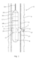
- Fig. 1 shows a punching tool 1 having just punched a hole 2 in a casing 3 in a borehole 4.
- the punching tool 1 comprises a tool body 5 having an axial extension 6, and a punching unit 7 is arranged in a bore 27 of the tool body and comprising a punch 9 movable between a retracted and a projected position and extending substantially radially in relation to the axial extension.
- the punching unit of the tool further comprises a hydraulic punch cylinder 11 moving the punch between the retracted and the projected position in order to punch a piece 12 out of a wall 13 of the casing 3.
- the punching tool 1 further comprises an abutment 10 arranged circumferentially opposite the punch about the tool body to abut the wall of the casing so that all force of the hydraulic cylinder is applied to the punching process.
- the abutment is fixedly connected with the tool body.
- the punching tool 1 is submerged into the well and powered through a wireline 14 and connected with the tool through a cable head 15.
- the punching tool 1 comprises a motor 17 for driving a pump 18 which drives the hydraulic cylinder.
- the motor is connected with the cable head 15 through an electronic section 16.
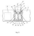
- the punch 9 has a hollow space 19 in which a piston 20 of the hydraulic punch cylinder 11 is arranged so that the punch 9 is able to move from its retracted position to its projected position, as shown, to punch a hole in the casing wall.
- the punch 9 moves inside an expandable space 31 in the hydraulic punch cylinder.
- the punch In one end of the punch 9, the punch has a punching edge 21 and in the other end in the tool body, the punch 9 has a flange 22 extending towards a piston rod 23 of the piston.
- a spring 24 is arranged which is compressed when the punch is in its projected position and while the space expands.
- the pump 18 illustrated with dotted lines in Fig. 2 provides fluid through fluid channels 25 into the punch cylinder 11 through inlets 26 in order to force the punch radially outwards from the tool body 5.
- the pump stops pumping fluid into the punch cylinder and the fluid is forced back into the fluid channel 25 by the decompressing force of the spring.
- Sealing means 28 is arranged in grooves 29 in the bore 27 of the tool body to seal against the punching unit 7.
- the punching force can be substantially increased compared to prior art mechanically operated solutions. Furthermore, tests have shown that the hole in the casing can be made with a higher degree of accuracy and that this cut is cleaner leaving almost no burrs on the edges. The prior art solutions leave substantial burrs on the edges hindering the insertion of a valve in the hole in a subsequent process. If the hole is made to open the casing to an inflow of well fluid, such as hydrocarbons also called oil and/or gas, the burrs hinder an optimal inflow, causing a more turbulent flow before the hole at the burring side.
- well fluid such as hydrocarbons also called oil and/or gas
- the abutment 10 projects radially from the tool body 5 and is therefore slidably arranged in a second bore 32 of the tool body activated by a second hydraulic cylinder 30 moving the abutment 10 radially in relation to the axial extension.
- the abutment has a hollow space 33 in which a second piston 34 moves compressing a second spring 35 between a second flange 36 in one end of the abutment opposite an outer face of the abutment abutting the inner wall of the casing.
- the radial movement of the abutment is performed by the pump pumping fluid into second fluid channels 37 into the expandable space 31 through second inlets 39.
- One pump may thus supply fluid to both the punch cylinder and the second cylinder.
- the fluid channels 25, 37 supplying fluid to the punch 9 and the abutment 10 may be one channel.
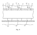
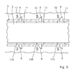
- the punching tool 1 may comprise several punching units 11 punching holes in the casing in a predetermined pattern, as shown in Fig. 4 .
- the punching tool can be used instead of a perforation gun, thereby avoiding the risky detonations downhole.
- the punching tool 1 comprises second punching units 11b also arranged circumferentially opposite the first punching units 11 about the tool body 5.
- the second punching units have the same design as the first punching units 11 and function as abutments in relation to the first punching units 11, and similarly the first punching units function as abutments to the second punching units 11b.
- the punching units in Fig. 5 are arranged having an angular spacing of 180°. In Fig.
- the punching tool 1 comprises more and third punching units 11c arranged in between the first and second punching units having both an angular spacing of 45° and a longitudinal spacing in the axial extension of the tool.
- the third punching units 11c are also arranged circumferentially opposite the third punching units 11c shown in Fig. 6 about the tool body.
- the punching tool shown in Fig. 5 thus comprises 10 punching units spaced apart to optimise the tool length and all the punching units may be supplied with fluid from the same pump through the same channel or through several channels.
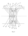
- the abutment 10 and the punch 9 engage one another in Fig. 7 so that they form one expandable space 31.
- the radial movement of the abutment and the punch thus occurs as one movement of both moving radially away from each other.
- the abutment 10 and the punch 9 form two fluidly connected hydraulic cylinders.
- a piston 20 is arranged in each cylinder.
- the pistons 20 are connected with the abutment 10 by screws 41, and the punch 9 is connected with two inserts 40 threadingly connected with a base part 42 of the punch forming a hollow space 19.
- the pistons are movable within each hollow space forming an expandable space 31 together with the abutment 10.
- the inserts 40 each have a flange 22 which together with the piston compresses a spring 24 while the space 31 expands to project the punch and the abutment from the tool body.
- the punching unit 7 thus comprises one punch, one abutment and two hydraulic cylinders forming one expandable space.
- the punch 9 and the abutment 10 are forced away from each other by means of fluid pumped into the expandable space 31 through fluid channels 25 and is let into the expandable space through a circumferential groove 43 leading the fluid in through the inlet 26 and into a cylinder bore 44.
- Sealing means 28 is arranged in grooves 29 in the through-bore 27 in which the punching unit 7 is arranged, preventing the fluid from escaping into the surroundings of the tool.
- a hollow rod 45 functioning as a stop element 45 is arranged penetrating both the punch and the abutment. Both comprise an elongated opening so that the punch 9 and the abutment 10 can move in relation the rod and each other.
- the rod is hollow to lead the fluid and has openings for the fluid to enter, thus leading the fluid into the expandable space 31.
- the fluid inlet 8 is thus positioned in the centre of the punching unit.
- the punching unit 7 is arranged so that hydraulic cylinders are arranged along the axial extension of the tool and in Fig. 8 , hydraulic cylinders are arranged along a line which is perpendicular to the axial extension 6 of the tool.
- the punching unit has substantially the same design as the punching unit 7 of Fig. 7 .
- the punching unit has a fluid channel 46 in the punch 9 to lead the fluid from the hollow rod 45 to one end of the hydraulic cylinder so that the fluid is injected into the space acting directly on the pistons.
- the initial movement of the punch 9 and the abutment 10 requires less fluid power.
- part of the punch 9 engages part of the abutment 10 to control the radial movement between the retracted and the projected position of the punch 9.
- the abutment 10 has radially extending guide elements 50 engaging radially extending tracks 51 of the punch 9.
- the punch 9 engages the abutment 10 on an outside thereof or vice versa so as to control the radial movement between the retracted and the projected position of the punch 9.
- the sealing means 28 is arranged in grooves in the punching unit 7 to seal against the through-bore and the tool body 5.
- the punching tool 1 is designed so that the distance between the retracted and the projected position of the punch is above 5 mm, preferably above 10 mm, more preferably above 20 mm, most preferably above 50 mm. However, this depends on the completion and the restrictions already present in the completion.
- the punching tool may be used to punch only a small hole having a diameter smaller than that of the punch, and thus the hole is made by the tip of the punch.
- it may be necessary to make small relief holes and even pump gas down through the outer casing in through the inner casing to force the fluid upwards.
- Such relief holes may also be necessary to even out the pressure between the casing and the annulus.
- the piece of the casing is not separate from the rest of the casing and is not flowing freely around in the annulus.
- the punching tool may have several abutments and one punch all of which are hydraulically activated so that the abutments are positioned on both sides of the punch and are projected radially until the punch presses against the inner wall of the casing. Subsequently, the punch is activated and the punch cuts its way into the casing wall without having to travel a certain length before reaching the inner casing wall. In this way, the punch is capable of penetrating thicker casings than if it had to travel a certain length before reaching the inner casing wall.
- the punch may be any kind of punch, e.g. comprising a pointed surface adapted to rupture the metal casing during the movement of the punch from the retracted to the projected position.
- the abutment has a curved and convex face which is adapted to abut an inner surface of a tubular metal casing during the punching.
- the abutment may comprise attachment elements so that the face of the abutment can be changed in relation to the inner surface of the metal casing.
- the abutment face may then change to a teethed surface or similar design to better be able to fasten the tool while punching the hole.
- the pump of the tool takes fluid in from the well through a filter but the tool may instead comprise a fluid reservoir, or the fluid is led from surface through the wireline which is thus also a supply line.
- fluid or well fluid any kind of fluid that may be present in oil or gas wells downhole, such as natural gas, oil, oil mud, crude oil, water, etc.
- gas is meant any kind of gas composition present in a well, completion, or open hole
- oil is meant any kind of oil composition, such as crude oil, an oil-containing fluid, etc.
- Gas, oil, and water fluids may thus all comprise other elements or substances than gas, oil, and/or water, respectively.
- a casing any kind of pipe, tubing, tubular, liner, string etc. used downhole in relation to oil or natural gas production.
- a downhole tractor can be used to push the tools all the way into position in the well.
- a downhole tractor is any kind of driving tool capable of pushing or pulling tools in a well downhole, such as a Well Tractor®.
Landscapes
- Life Sciences & Earth Sciences (AREA)
- Engineering & Computer Science (AREA)
- Geology (AREA)
- Mining & Mineral Resources (AREA)
- Physics & Mathematics (AREA)
- Environmental & Geological Engineering (AREA)
- Fluid Mechanics (AREA)
- General Life Sciences & Earth Sciences (AREA)
- Geochemistry & Mineralogy (AREA)
- Perforating, Stamping-Out Or Severing By Means Other Than Cutting (AREA)
- Earth Drilling (AREA)
Priority Applications (10)
| Application Number | Priority Date | Filing Date | Title |
|---|---|---|---|
| EP11183494A EP2574721A1 (fr) | 2011-09-30 | 2011-09-30 | Outil de poinçonnage |
| RU2014114427/03A RU2014114427A (ru) | 2011-09-30 | 2012-09-27 | Перфорационный инструмент |
| CA2848818A CA2848818A1 (fr) | 2011-09-30 | 2012-09-27 | Outil de poinconnage |
| BR112014005115A BR112014005115A2 (pt) | 2011-09-30 | 2012-09-27 | ferramenta de perfuração |
| US14/344,473 US20140374100A1 (en) | 2011-09-30 | 2012-09-27 | Punching tool |
| EP12762624.0A EP2761128A1 (fr) | 2011-09-30 | 2012-09-27 | Outil de poinçonnage |
| PCT/EP2012/069084 WO2013045550A1 (fr) | 2011-09-30 | 2012-09-27 | Outil de poinçonnage |
| CN201280044906.2A CN103797212A (zh) | 2011-09-30 | 2012-09-27 | 冲击工具 |
| MX2014003023A MX2014003023A (es) | 2011-09-30 | 2012-09-27 | Herramienta de punzonar. |
| AU2012314450A AU2012314450A1 (en) | 2011-09-30 | 2012-09-27 | A punching tool |
Applications Claiming Priority (1)
| Application Number | Priority Date | Filing Date | Title |
|---|---|---|---|
| EP11183494A EP2574721A1 (fr) | 2011-09-30 | 2011-09-30 | Outil de poinçonnage |
Publications (1)
| Publication Number | Publication Date |
|---|---|
| EP2574721A1 true EP2574721A1 (fr) | 2013-04-03 |
Family
ID=46924462
Family Applications (2)
| Application Number | Title | Priority Date | Filing Date |
|---|---|---|---|
| EP11183494A Withdrawn EP2574721A1 (fr) | 2011-09-30 | 2011-09-30 | Outil de poinçonnage |
| EP12762624.0A Withdrawn EP2761128A1 (fr) | 2011-09-30 | 2012-09-27 | Outil de poinçonnage |
Family Applications After (1)
| Application Number | Title | Priority Date | Filing Date |
|---|---|---|---|
| EP12762624.0A Withdrawn EP2761128A1 (fr) | 2011-09-30 | 2012-09-27 | Outil de poinçonnage |
Country Status (9)
| Country | Link |
|---|---|
| US (1) | US20140374100A1 (fr) |
| EP (2) | EP2574721A1 (fr) |
| CN (1) | CN103797212A (fr) |
| AU (1) | AU2012314450A1 (fr) |
| BR (1) | BR112014005115A2 (fr) |
| CA (1) | CA2848818A1 (fr) |
| MX (1) | MX2014003023A (fr) |
| RU (1) | RU2014114427A (fr) |
| WO (1) | WO2013045550A1 (fr) |
Cited By (2)
| Publication number | Priority date | Publication date | Assignee | Title |
|---|---|---|---|---|
| WO2014207025A3 (fr) * | 2013-06-26 | 2015-06-18 | Welltec A/S | Système d'extraction au gaz et procédé d'extraction au gaz |
| WO2017211825A1 (fr) * | 2016-06-07 | 2017-12-14 | Welltec A/S | Outil fonctionnel de fond de trou |
Families Citing this family (7)
| Publication number | Priority date | Publication date | Assignee | Title |
|---|---|---|---|---|
| EP2909427B1 (fr) * | 2012-10-16 | 2019-08-21 | Maersk Olie Og Gas A/S | Dispositif et procédé d'étanchéité |
| US9394768B2 (en) * | 2013-09-30 | 2016-07-19 | Passerby Inc. | Hydromecanical piercing perforator and method of operation thereof |
| US10287860B2 (en) * | 2013-11-14 | 2019-05-14 | Halliburton Energy Services, Inc. | Downhole mechanical tubing perforator |
| BR112017017663B1 (pt) | 2015-03-03 | 2022-10-25 | Welltec A/S | Ferramenta de acesso a fundo de poço, sistema de fundo de poço e uso de uma ferramenta de acesso a fundo de poço |
| CA3097675C (fr) * | 2018-05-25 | 2023-03-21 | Aarbakke Innovation As | Procede de modification de dispositifs installes de regulation d'ecoulement de puits de forage |
| EP3663509A1 (fr) | 2018-12-06 | 2020-06-10 | Welltec A/S | Outil de fond de trou comportant une longue rallonge en saillie |
| BR112021022072A2 (pt) * | 2019-05-15 | 2021-12-28 | Shell Int Research | Ferramenta de fundo de poço, e, método para injetar um vedante em um anular em torno de um invólucro em um orifício de furo |
Citations (4)
| Publication number | Priority date | Publication date | Assignee | Title |
|---|---|---|---|---|
| US2457277A (en) * | 1941-08-01 | 1948-12-28 | Schlumberger Marcel | Well conditioning apparatus |
| US3720262A (en) * | 1971-01-21 | 1973-03-13 | D Grable | Method and apparatus for sub-surface deformation of well pipe |
| WO2007085047A1 (fr) * | 2006-01-24 | 2007-08-02 | Well Ops Sea Pty Ltd | Dispositif de colmatage a distance pour puits |
| US20110061874A1 (en) * | 2009-09-11 | 2011-03-17 | Prospector Drilling & Tool Co., Inc. | Tool and method for enhancing the extraction of landfill gas |
Family Cites Families (6)
| Publication number | Priority date | Publication date | Assignee | Title |
|---|---|---|---|---|
| US3876000A (en) * | 1973-10-29 | 1975-04-08 | Schlumberger Technology Corp | Inflatable packer drill stem testing apparatus |
| CN1013781B (zh) * | 1986-12-30 | 1991-09-04 | 赫曼·J·舒尔史特 | 井管钻孔器件及方法 |
| RU2211310C1 (ru) * | 2002-03-11 | 2003-08-27 | Вагапов Самат Юнирович | Скважинный пробойник-перфоратор |
| US7073394B2 (en) * | 2004-04-05 | 2006-07-11 | Rosemount Inc. | Scalable averaging insertion vortex flow meter |
| GB2433754B (en) * | 2005-12-30 | 2009-04-22 | Schlumberger Holdings | Wellbore intervention tool |
| GB0801730D0 (en) * | 2008-01-31 | 2008-03-05 | Red Spider Technology Ltd | Retrofit gas lift straddle |
-
2011
- 2011-09-30 EP EP11183494A patent/EP2574721A1/fr not_active Withdrawn
-
2012
- 2012-09-27 BR BR112014005115A patent/BR112014005115A2/pt not_active IP Right Cessation
- 2012-09-27 WO PCT/EP2012/069084 patent/WO2013045550A1/fr active Application Filing
- 2012-09-27 RU RU2014114427/03A patent/RU2014114427A/ru not_active Application Discontinuation
- 2012-09-27 CA CA2848818A patent/CA2848818A1/fr not_active Abandoned
- 2012-09-27 CN CN201280044906.2A patent/CN103797212A/zh active Pending
- 2012-09-27 EP EP12762624.0A patent/EP2761128A1/fr not_active Withdrawn
- 2012-09-27 US US14/344,473 patent/US20140374100A1/en not_active Abandoned
- 2012-09-27 AU AU2012314450A patent/AU2012314450A1/en not_active Abandoned
- 2012-09-27 MX MX2014003023A patent/MX2014003023A/es not_active Application Discontinuation
Patent Citations (4)
| Publication number | Priority date | Publication date | Assignee | Title |
|---|---|---|---|---|
| US2457277A (en) * | 1941-08-01 | 1948-12-28 | Schlumberger Marcel | Well conditioning apparatus |
| US3720262A (en) * | 1971-01-21 | 1973-03-13 | D Grable | Method and apparatus for sub-surface deformation of well pipe |
| WO2007085047A1 (fr) * | 2006-01-24 | 2007-08-02 | Well Ops Sea Pty Ltd | Dispositif de colmatage a distance pour puits |
| US20110061874A1 (en) * | 2009-09-11 | 2011-03-17 | Prospector Drilling & Tool Co., Inc. | Tool and method for enhancing the extraction of landfill gas |
Cited By (5)
| Publication number | Priority date | Publication date | Assignee | Title |
|---|---|---|---|---|
| WO2014207025A3 (fr) * | 2013-06-26 | 2015-06-18 | Welltec A/S | Système d'extraction au gaz et procédé d'extraction au gaz |
| CN105283630A (zh) * | 2013-06-26 | 2016-01-27 | 韦尔泰克有限公司 | 气举系统和气举方法 |
| AU2014301129B2 (en) * | 2013-06-26 | 2017-04-13 | Welltec A/S | A gas lift system and a gas lift method |
| WO2017211825A1 (fr) * | 2016-06-07 | 2017-12-14 | Welltec A/S | Outil fonctionnel de fond de trou |
| US10557312B2 (en) | 2016-06-07 | 2020-02-11 | Welltec A/S | Downhole operational tool |
Also Published As
| Publication number | Publication date |
|---|---|
| RU2014114427A (ru) | 2015-11-10 |
| US20140374100A1 (en) | 2014-12-25 |
| AU2012314450A1 (en) | 2014-05-22 |
| CA2848818A1 (fr) | 2013-04-04 |
| EP2761128A1 (fr) | 2014-08-06 |
| BR112014005115A2 (pt) | 2017-04-18 |
| WO2013045550A1 (fr) | 2013-04-04 |
| MX2014003023A (es) | 2014-05-28 |
| CN103797212A (zh) | 2014-05-14 |
Similar Documents
| Publication | Publication Date | Title |
|---|---|---|
| EP2574721A1 (fr) | Outil de poinçonnage | |
| USRE49029E1 (en) | Packer apparatus and method of sealing well casing | |
| US20080236829A1 (en) | Casing profiling and recovery system | |
| US10208572B2 (en) | Apparatus and method for perforating a subterranean formation | |
| EP2643544B1 (fr) | Élément poinçon de fond de trou | |
| US10066466B2 (en) | Delivering pressurised fluid | |
| CA2944172C (fr) | Systeme d'expansion | |
| CN104704196A (zh) | 电缆泵 | |
| EP3891355B1 (fr) | Outil de fond de trou comportant une longue rallonge en saillie | |
| EP3526440B1 (fr) | Ensemble expansif |
Legal Events
| Date | Code | Title | Description |
|---|---|---|---|
| PUAI | Public reference made under article 153(3) epc to a published international application that has entered the european phase |
Free format text: ORIGINAL CODE: 0009012 |
|
| AK | Designated contracting states |
Kind code of ref document: A1 Designated state(s): AL AT BE BG CH CY CZ DE DK EE ES FI FR GB GR HR HU IE IS IT LI LT LU LV MC MK MT NL NO PL PT RO RS SE SI SK SM TR |
|
| AX | Request for extension of the european patent |
Extension state: BA ME |
|
| STAA | Information on the status of an ep patent application or granted ep patent |
Free format text: STATUS: THE APPLICATION IS DEEMED TO BE WITHDRAWN |
|
| 18D | Application deemed to be withdrawn |
Effective date: 20131005 |