EP2574544B1 - Method of integrating an avionics bay and floor structure for implementing the method - Google Patents
Method of integrating an avionics bay and floor structure for implementing the method Download PDFInfo
- Publication number
- EP2574544B1 EP2574544B1 EP12186411.0A EP12186411A EP2574544B1 EP 2574544 B1 EP2574544 B1 EP 2574544B1 EP 12186411 A EP12186411 A EP 12186411A EP 2574544 B1 EP2574544 B1 EP 2574544B1
- Authority
- EP
- European Patent Office
- Prior art keywords
- bay
- floor
- floor structure
- structure according
- space
- Prior art date
- Legal status (The legal status is an assumption and is not a legal conclusion. Google has not performed a legal analysis and makes no representation as to the accuracy of the status listed.)
- Active
Links
- 238000000034 method Methods 0.000 title claims description 14
- 230000010354 integration Effects 0.000 claims description 13
- 238000009423 ventilation Methods 0.000 claims description 10
- 238000007664 blowing Methods 0.000 claims description 7
- 238000000605 extraction Methods 0.000 claims description 6
- 239000012530 fluid Substances 0.000 claims description 3
- 230000002093 peripheral effect Effects 0.000 claims description 3
- 230000001681 protective effect Effects 0.000 claims description 3
- 238000007789 sealing Methods 0.000 claims description 3
- 230000003014 reinforcing effect Effects 0.000 claims 1
- 238000005192 partition Methods 0.000 description 3
- 238000012423 maintenance Methods 0.000 description 2
- 230000002787 reinforcement Effects 0.000 description 2
- RZVHIXYEVGDQDX-UHFFFAOYSA-N 9,10-anthraquinone Chemical compound C1=CC=C2C(=O)C3=CC=CC=C3C(=O)C2=C1 RZVHIXYEVGDQDX-UHFFFAOYSA-N 0.000 description 1
- 210000001015 abdomen Anatomy 0.000 description 1
- 230000005465 channeling Effects 0.000 description 1
- 238000001816 cooling Methods 0.000 description 1
- 230000008878 coupling Effects 0.000 description 1
- 238000010168 coupling process Methods 0.000 description 1
- 238000005859 coupling reaction Methods 0.000 description 1
- 238000001514 detection method Methods 0.000 description 1
- 238000010586 diagram Methods 0.000 description 1
- 230000000763 evoking effect Effects 0.000 description 1
- 230000005484 gravity Effects 0.000 description 1
- 238000009434 installation Methods 0.000 description 1
- 230000035515 penetration Effects 0.000 description 1
- 239000000779 smoke Substances 0.000 description 1
- 239000003351 stiffener Substances 0.000 description 1
Images
Classifications
-
- B—PERFORMING OPERATIONS; TRANSPORTING
- B64—AIRCRAFT; AVIATION; COSMONAUTICS
- B64D—EQUIPMENT FOR FITTING IN OR TO AIRCRAFT; FLIGHT SUITS; PARACHUTES; ARRANGEMENTS OR MOUNTING OF POWER PLANTS OR PROPULSION TRANSMISSIONS IN AIRCRAFT
- B64D13/00—Arrangements or adaptations of air-treatment apparatus for aircraft crew or passengers, or freight space, or structural parts of the aircraft
-
- B—PERFORMING OPERATIONS; TRANSPORTING
- B64—AIRCRAFT; AVIATION; COSMONAUTICS
- B64C—AEROPLANES; HELICOPTERS
- B64C1/00—Fuselages; Constructional features common to fuselages, wings, stabilising surfaces or the like
- B64C1/18—Floors
-
- B—PERFORMING OPERATIONS; TRANSPORTING
- B64—AIRCRAFT; AVIATION; COSMONAUTICS
- B64D—EQUIPMENT FOR FITTING IN OR TO AIRCRAFT; FLIGHT SUITS; PARACHUTES; ARRANGEMENTS OR MOUNTING OF POWER PLANTS OR PROPULSION TRANSMISSIONS IN AIRCRAFT
- B64D13/00—Arrangements or adaptations of air-treatment apparatus for aircraft crew or passengers, or freight space, or structural parts of the aircraft
- B64D13/06—Arrangements or adaptations of air-treatment apparatus for aircraft crew or passengers, or freight space, or structural parts of the aircraft the air being conditioned
- B64D2013/0603—Environmental Control Systems
- B64D2013/0614—Environmental Control Systems with subsystems for cooling avionics
-
- Y—GENERAL TAGGING OF NEW TECHNOLOGICAL DEVELOPMENTS; GENERAL TAGGING OF CROSS-SECTIONAL TECHNOLOGIES SPANNING OVER SEVERAL SECTIONS OF THE IPC; TECHNICAL SUBJECTS COVERED BY FORMER USPC CROSS-REFERENCE ART COLLECTIONS [XRACs] AND DIGESTS
- Y02—TECHNOLOGIES OR APPLICATIONS FOR MITIGATION OR ADAPTATION AGAINST CLIMATE CHANGE
- Y02T—CLIMATE CHANGE MITIGATION TECHNOLOGIES RELATED TO TRANSPORTATION
- Y02T50/00—Aeronautics or air transport
- Y02T50/40—Weight reduction
Definitions
- the invention relates to a method for integrating an avionics bay into an aircraft floor structure, as well as to an aircraft floor structure, in particular a cockpit structure, incorporating such an array.
- the invention relates to the optimized implementation of an avionics bay grouping one or more electrical and / or electronic furniture, incorporating electrical and / or electronic equipment, for example the calculators and their avionics functions. Ventilation of such furniture in such a congested space is one aspect of the field of the invention that can be taken into consideration.
- the furniture such as electric and / or electronic bays are conventionally arranged vertically and integrated in the hold under the cockpit while extending in part in the cargo volume located under the space dedicated to the passenger cabin.
- the terms “vertical”, “horizontal”, “upper”, “lower” and their derivatives refer to positions in standard mode of use with reference to universal gravity.
- These furniture are conventionally arranged vertically and are formed on the basis of a carrier frame comprising at least two uprights on which are mounted horizontal shelves. Shelves and uprights are arranged in sealed boxes with single or double compartment. These boxes provide a structural function as well as an integrated air circulation function.
- the shelves serve as support for the electronic modules (computers, cards, additional disks, electronic equipment, modules power, etc.) via standardized intermediate racks. These racks provide both the mechanical connection and the electrical connection of each module housed in the rack.
- an intermediate electrical network provides for each module, or each interconnection between modules, the connection to the external power network called "aircraft network” via cut-off plates.
- the electronic modules dissipate heat and are sensitive to high temperatures and temperature variations, it is advantageous to ventilate them. To this end, it is conventionally provided to cool each module by blowing a fresh air flow through the module and extract the hot air above each module.
- the furniture is interconnected to the general ventilation circuit of the aircraft.
- the furniture is generally attached to the structure of the aircraft by means of tenons (Chappe type) and connecting rod.
- tenons Choappe type
- connecting rod A global isostatic link is thus obtained with respect to the aircraft structure, which makes it possible to take into account the deformations of the structure of the aircraft.
- the document FR-2933241 shows an under floor housing system for electronic boxes and is regarded as the closest prior art.
- the object of the invention is to overcome these drawbacks by proposing an avionics bay integration, advantageously of great capacity for housing electrical / electronic functions, in a floor zone, the integration being able to be associated with an appropriate ventilation at this location. .
- the present invention relates to a method of integrating an avionics bay into an aircraft floor structure, as defined by claim 1.
- a space is previously released in the floor structure.
- the bay is then integrated in a horizontal position in this landscaped space. Direct access to this bay in the upper face is provided at the floor level by a protection also acting floor.
- forced ventilation of the bay can be achieved by blowing fresh air distributed vertically from the lower wall of the bay and extracted after heat exchange by the upper wall. Furthermore, a shear load transfer is achieved by a reinforcement of the structural volume around said space. In addition, an access opposite The lower bay can also be laid out from the forward tip belly.
- the method according to the invention also provides a fresh air supply function laterally between the upper and lower walls before being deflected towards the lower wall and then distributed vertically from the bottom wall, a sealing function and draining fluid out of the bay, and / or an air manifold function dedicated to the hood for extraction by a ducted airflow.
- the invention also relates to an aircraft floor structure, in particular a cockpit, capable of integrating at least one such bay according to the method above, as defined by claim 8.
- This structure comprises a floor of walk and a structural volume supported by sleepers on which rests the floor. The sleepers and the floor are cut so that a space is released in the structural volume to integrate the bay in horizontal position.
- lateral openings formed in the frame are able, by coupling with vertical walls, to allow fresh air to be blown upwards from the bottom wall of the bay to the top cover and an air extraction by a extractor on the upper face.
- load transfer sails are arranged.
- the bay may include a hinged peripheral frame with at least one protective cover for direct access to this bay at the floor and a rear access opening at the bottom face.
- the bay integrated in a horizontal position in this space, can be secured by specific fixing means to the floor and / or cut beams.
- the invention applies in particular to the floor structure of an aircraft cockpit which is a privileged secure space, the structural volume of the floor then separating the cockpit from the nose-tip hold.
- the floor of other areas of the aircraft can also be used, especially that of dedicated passage areas (kitchen, toilets, etc.).
- the "front”, “rear” and “lateral” qualifiers and their derivatives used in the present description define element positions with respect to the standard relative positioning of these elements in a plane disposed on the ground.
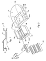
- the example described with reference to the global view of the figure 2 refers to a cockpit floor.
- the cockpit step 1 is pierced to release a volume 2 in its structure 10 to house an avionics bay 3 according to the arrow F1.
- An advantageous location for this volume 2 is located in the access corridor to the cockpits (see figure 4 ).
- the floor structure 10 consists of boxes 11, the walls of which are sleepers 110. This floor structure 10 is released by cutting the sleepers 110 to an appropriate length (a few sleepers are shown schematically in dashed lines). Stiffening webs 113 are secured to the right and between these cuts to promote the transfer of load on the uncut floor structure.
- the volume 2 is limited longitudinally by these webs 113 and transversely by cross members 110 uncut. The dimensions of the volume 2 are substantially those of the bay 3 to integrate.
- the avionics bay 3 is a piece of furniture consisting of a carrier frame 31 and longitudinal internal partitions 32 forming shelves 33 able to accommodate, in this example, racks 34 along their entire length called "maxi racks". These maxi racks house thin modules in card format 35.
- the frame 31 consists of two longitudinal walls 311 and two transverse walls 312 according to their position after integration.
- the bay 3 is closed by two covers 36 relatively thick, for example of the order of 50 to 60 mm thick, relative to the thickness of the frame and partitions, to maintain a resistance equivalent to the rest 1.
- This multifunctional aspect of the hoods that act as floor allows a gain in mass and cost.
- the walls 311, 312 and the cover 36 of the bay 3 are arranged in connection with the stiffening webs 113.
- each cover is sealed and has joints 39 connecting with the frame 31 particularly selected for their sealing.
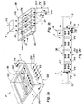
- FIG. 3a The perspective view of the figure 3a , concerning an example of simplified avionics bay 3 'with two compartments 321 and 322, shows that the longitudinal walls 311 have calibrated orifices 331 of the input of blowing fresh air according to the flow symbolized by the parallel arrows F2.
- the ventilation of a single compartment 321 is described, that of the other compartment 322 being in every way similar.
- the fresh air then circulates in the longitudinal wall 311 to be oriented towards the bottom 320 of the compartment 321 (arrow F3) and then to circulate (arrows F4) in it from the bottom.
- the air rises to the top of the furniture 3 '(arrows F5) and leaves it via the extractor 4 (Arrow F6) secured to the edge of the cover 36 (shown in transparency).
- the lid 36 itself is compartmentalized by longitudinal stiffeners 360 for channeling air from orifices 332 formed in the walls of the lid 36 and dimensioned in the structural boundaries.
- the arrows F5 indicate the flow of air in the cover 36.
- the air coming from the orifices 331 passes into the wall 311 of the frame 31 and is then deflected towards the bottom of the chassis (arrow F3) because of the lower position of the the internal orifice 333 of the wall 311.
- the sectional view of the figure 3c uses the same arrows to indicate the flow of air in the bay 3 ': the arrows F2 illustrate the flow of air from the structure 10, the arrows F3 the deflection towards the bottom of the frame, the arrows F4 the circulation in either direction at the bottom wall 320, the arrows F7 the rise of the air and the arrow F6 its extraction in the extractor 4.
- the air can also come (arrows F8 ) of the hold via appropriate tubing (not shown).
- the other references relate to the elements already described: the covers 36, the floor 1, the frame 31
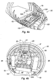
- the released and reinforced volume 2 extends transversely over a large part of the width of the cockpit 20. This volume is delimited by lateral portions 15 of the floor structure which conduct the ventilation.
- the air comes from tubings (not shown) and is channeled through orifices 151 pierced in internal partitions 150 and in longitudinal walls 152. Alternatively, the pipes can arrive directly on the bay without passing through the floor portions.
- a 3 "avionics bay is easily integrated into the released volume 2 of the cockpit 20 floor structure 10 during the cockpit layout
- the avionics bay 3" is integrated more precisely over a width covering the entire corridor 21 d access to the cockpit seats 22 and 23 of the cockpit 20.
- the fixing of the bay is performed in a very simple manner in a few discrete points, at the angles and sides, for example by brackets or equivalent maintained by screw systems. nuts.
- Other furniture 35 is arranged laterally on the lateral ventilation portions 15 formed in the structure 10. According to the configurations, other parts of the floor structure, for example located just behind the pilot's seats 25 or between these seats, can to be released to accommodate avionics bays of appropriate appropriate form.
- the invention is not limited to the embodiments described and shown.
- the hoods of the bay can serve as thermal and acoustic protection of the cockpit vis-à-vis a technical area in the cargo hold.
- these covers can serve as fire and smoke protection.
- the avionics bay may have one or multiple covers in place of the two covers described.
Description
L'invention se rapporte à un procédé d'intégration d'une baie avionique dans une structure de plancher d'un aéronef, ainsi qu'à une structure de plancher d'aéronef, en particulier de cockpit, intégrant une telle baie.The invention relates to a method for integrating an avionics bay into an aircraft floor structure, as well as to an aircraft floor structure, in particular a cockpit structure, incorporating such an array.
En application principale, l'invention concerne la mise en place optimisée d'une baie avionique regroupant un ou plusieurs meubles électriques et/ou électroniques, intégrant les équipements électriques et/ou électroniques, par exemple particulier les calculateurs et leurs fonctions avioniques. La ventilation de ces meubles dans un tel espace encombré est un aspect du domaine de l'invention qui peut être pris en considération.In main application, the invention relates to the optimized implementation of an avionics bay grouping one or more electrical and / or electronic furniture, incorporating electrical and / or electronic equipment, for example the calculators and their avionics functions. Ventilation of such furniture in such a congested space is one aspect of the field of the invention that can be taken into consideration.
Jusqu'à présent, les meubles tels que les baies électriques et/ou électroniques sont classiquement disposés verticalement et intégrés en soute sous le cockpit tout en s'étendant en partie dans le volume cargo situé sous l'espace dédié à la cabine de passagers. Les termes « vertical », « horizontal », « supérieur », « inférieur », ainsi que leurs dérivés, se rapportent à des positions en mode d'utilisation standard en référence à la gravité universelle.Until now, the furniture such as electric and / or electronic bays are conventionally arranged vertically and integrated in the hold under the cockpit while extending in part in the cargo volume located under the space dedicated to the passenger cabin. The terms "vertical", "horizontal", "upper", "lower" and their derivatives refer to positions in standard mode of use with reference to universal gravity.
Ces meubles sont classiquement disposés verticalement et sont constitués sur la base d'un châssis porteur comprenant au moins deux montants sur lesquels sont montés des étagères horizontales. Les étagères et les montants sont agencés en caissons étanches à simple ou double compartiment. Ces caissons assurent une fonction structurale ainsi qu'une fonction de circulation d'air intégré.These furniture are conventionally arranged vertically and are formed on the basis of a carrier frame comprising at least two uprights on which are mounted horizontal shelves. Shelves and uprights are arranged in sealed boxes with single or double compartment. These boxes provide a structural function as well as an integrated air circulation function.
Les étagères servent de support aux modules électroniques (calculateurs, cartes, disques additionnels, équipements électroniques, modules de puissance, etc.) via des racks intermédiaires standardisés. Ces racks assurent tant la liaison mécanique que la connexion électrique de chaque module logé dans le rack.The shelves serve as support for the electronic modules (computers, cards, additional disks, electronic equipment, modules power, etc.) via standardized intermediate racks. These racks provide both the mechanical connection and the electrical connection of each module housed in the rack.
Sur la face arrière du meuble, un réseau électrique intermédiaire assure pour chaque module, ou chaque interconnexion entre modules, la liaison au réseau électrique extérieur dit « réseau avion » via des platines de coupure.On the back of the cabinet, an intermediate electrical network provides for each module, or each interconnection between modules, the connection to the external power network called "aircraft network" via cut-off plates.
Sur la face avant, un accès aisé aux calculateurs est aménagé pour les intégrer et les remplacer rapidement lors d'une détection de fonction défectueuse en phase de maintenance ou de contrôle pré-vol.On the front panel, easy access to computers is arranged to integrate and replace quickly when a faulty function detection in maintenance phase or pre-flight control.
Ces accès en faces avant et arrière sont facilités par la position verticale des meubles.These front and rear access are facilitated by the vertical position of the furniture.
Dans un standard plus récent d'intégration sous forme de « cabinet », un seul rack dit « maxi rack » occupe toute une étagère. L'intégration électrique arrière est alors simplifiée car tous les connecteurs électriques étant distribués sur une même carte-mère intégrée au cabinet. Dans ce cabinet, les fonctions électriques sont distribuées par des cartes de type « blade » (« lame » en terminologie anglaise, ce terme évoquant la faible épaisseur relative des cartes). Les cabinets sont regroupés dans un caisson ou disposés individuellement à l'instar des étagères.In a more recent standard of integration as a "cabinet", a single rack called "maxi rack" occupies a whole shelf. The rear electrical integration is then simplified because all electrical connectors are distributed on a single integrated motherboard cabinet. In this cabinet, the electrical functions are distributed by "blade" type cards ("blade" in English terminology, this term evoking the small relative thickness of the cards). Cabinets are grouped in a box or individually arranged like shelves.
Les modules électroniques dissipant de la chaleur et étant sensibles aux températures élevées ainsi qu'aux variations de température, il est avantageux de les ventiler. A cette fin, il est classiquement prévu de refroidir chaque module par le soufflage d'un flux d'air frais qui traverse le module puis d'extraire l'air chaud au-dessus de chaque module. Le meuble est interconnecté au circuit général de ventilation de l'aéronef.Since the electronic modules dissipate heat and are sensitive to high temperatures and temperature variations, it is advantageous to ventilate them. To this end, it is conventionally provided to cool each module by blowing a fresh air flow through the module and extract the hot air above each module. The furniture is interconnected to the general ventilation circuit of the aircraft.
Afin d'optimiser l'espace disponible et d'augmenter ainsi le nombre de modules, il est connu d'intégrer le circuit de refroidissement directement dans le châssis du meuble pour assurer un échange thermique avec l'air circulant dans le caisson. Ainsi, comme illustré par la vue en coupe d'une étagère G selon la
Par ailleurs, les meubles sont en général fixés à la structure de l'aéronef par des liaisons par tenon (de type Chappe) et bielle. Une liaison globale isostatique est ainsi obtenue par rapport à la structure aéronef, ce qui permet de prendre en compte les déformations de la structure de l'aéronef.In addition, the furniture is generally attached to the structure of the aircraft by means of tenons (Chappe type) and connecting rod. A global isostatic link is thus obtained with respect to the aircraft structure, which makes it possible to take into account the deformations of the structure of the aircraft.
Cependant, il est à présent recherché d'installer les baies électriques et/ou électroniques dans des espaces sécurisés car ces baies, qui intègrent de plus en plus l'ensemble des fonctions de commande et de contrôle, sont d'une importance vitale. Un espace sécurisé approprié serait en particulier le cockpit de l'aéronef.However, it is now sought to install the electrical and / or electronic bays in secure spaces because these bays, which integrate more and more all the control and control functions, are of vital importance. An appropriate secure space would be in particular the cockpit of the aircraft.
L'intégration de tels meubles dans un cockpit n'a pu jusqu'à présent être concrétisée du fait des problèmes d'encombrement qu'une telle installation entraîne, difficilement compatibles avec une ventilation des baies ou meubles avioniques intégrant des circuits électroniques.The integration of such furniture in a cockpit has so far been realized because of the congestion problems that such an installation causes, hardly compatible with a ventilation of the bays or avionics furniture incorporating electronic circuits.
Le document
L'invention vise à s'affranchir de ces inconvénients en proposant une intégration de baie avionique, avantageusement de grande capacité de logement de fonctions électriques/électroniques, dans une zone de plancher, l'intégration pouvant être associée à une ventilation appropriée à cet emplacement.The object of the invention is to overcome these drawbacks by proposing an avionics bay integration, advantageously of great capacity for housing electrical / electronic functions, in a floor zone, the integration being able to be associated with an appropriate ventilation at this location. .
Plus précisément, la présente invention a pour objet un procédé d'intégration d'une baie avionique dans une structure de plancher d'un aéronef , tel que défini par la revendication 1. Un espace est préalablement libéré dans la structure de plancher. La baie est ensuite intégrée en position horizontale dans cet espace aménagé. Un accès direct à cette baie en face supérieure est aménagé au niveau du plancher par une protection faisant également fonction de plancher.More specifically, the present invention relates to a method of integrating an avionics bay into an aircraft floor structure, as defined by claim 1. A space is previously released in the floor structure. The bay is then integrated in a horizontal position in this landscaped space. Direct access to this bay in the upper face is provided at the floor level by a protection also acting floor.
De manière préférée, une ventilation forcée de la baie peut être réalisée par un soufflage d'air frais distribué verticalement à partir de la paroi inférieure de la baie puis extrait après échange thermique par la paroi supérieure. Par ailleurs, un transfert de charge par cisaillement est réalisé par un renforcement du volume structural autour dudit espace. De plus, un accès en face inférieure de la baie peut également être aménagé à partir de la soute de pointe avant.Preferably, forced ventilation of the bay can be achieved by blowing fresh air distributed vertically from the lower wall of the bay and extracted after heat exchange by the upper wall. Furthermore, a shear load transfer is achieved by a reinforcement of the structural volume around said space. In addition, an access opposite The lower bay can also be laid out from the forward tip belly.
Selon des particularités avantageuses, le procédé selon l'invention prévoit également une fonction de fourniture d'air frais latéralement entre les parois supérieure et inférieure avant d'être dévié vers la paroi inférieure puis distribué verticalement depuis la paroi inférieure, une fonction d'étanchéité et de drainage de fluide hors de la baie, et/ou une fonction de collecteur d'air dédiée au capot en vue d'une extraction par un écoulement d'air canalisé.According to advantageous features, the method according to the invention also provides a fresh air supply function laterally between the upper and lower walls before being deflected towards the lower wall and then distributed vertically from the bottom wall, a sealing function and draining fluid out of the bay, and / or an air manifold function dedicated to the hood for extraction by a ducted airflow.
L'invention se rapporte également à une structure de plancher d'aéronef, en particulier d'un cockpit, apte à intégrer au moins une telle baie selon le procédé ci-dessus, comme défini par la revendication 8. Cette structure comporte un plancher de marche et un volume structural étayé par des traverses sur lequel repose le plancher. Les traverses et le plancher sont découpés de sorte qu'un espace est libéré dans le volume structural pour y intégrer la baie en position horizontale.The invention also relates to an aircraft floor structure, in particular a cockpit, capable of integrating at least one such bay according to the method above, as defined by claim 8. This structure comprises a floor of walk and a structural volume supported by sleepers on which rests the floor. The sleepers and the floor are cut so that a space is released in the structural volume to integrate the bay in horizontal position.
De manière avantageuse, des ouvertures latérales formées dans le châssis sont aptes par couplage avec des parois verticales à permettre un soufflage d'air frais ascensionnel à partir de la paroi inférieure de la baie jusqu'au capot supérieur et une extraction d'air par un extracteur en face supérieure. Par ailleurs, au droit et entre les poutrelles découpées, des voiles de transfert de charge sont agencés. De plus, la baie peut comporter un châssis périphérique articulé avec au moins un capot de protection d'accès direct à cette baie au niveau du plancher et une ouverture arrière d'accès en face inférieure. En outre, la baie, intégrée en position horizontale dans cet espace, peut être solidarisée par des moyens de fixation ponctuels au plancher et/ou aux poutrelles découpées.Advantageously, lateral openings formed in the frame are able, by coupling with vertical walls, to allow fresh air to be blown upwards from the bottom wall of the bay to the top cover and an air extraction by a extractor on the upper face. Furthermore, right and between the cut beams, load transfer sails are arranged. In addition, the bay may include a hinged peripheral frame with at least one protective cover for direct access to this bay at the floor and a rear access opening at the bottom face. In addition, the bay, integrated in a horizontal position in this space, can be secured by specific fixing means to the floor and / or cut beams.
Selon certains modes de réalisation préférés :
- la baie est compartimentée en caissons comportant des parois verticales aptes à permettre le soufflage d'air frais ascensionnel dans chaque compartiment ;
- le volume structural du plancher est compartimenté en caissons ;
- les ouvertures latérales sont équipées de diaphragme ;
- les parois et le capot sont agencés en liaison avec les voiles raidisseurs perforés.
- the bay is compartmentalized in boxes with vertical walls able to allow the blowing of fresh air in each compartment;
- the structural volume of the floor is compartmentalized in boxes;
- the lateral openings are equipped with diaphragm;
- the walls and the cover are arranged in connection with the perforated stiffening webs.
L'invention s'applique en particulier à la structure de plancher d'un cockpit d'aéronef qui est un espace sécurisé privilégié, le volume structural du plancher séparant alors le cockpit de la soute de pointe avant. Le plancher d'autres zones de l'aéronef peut également être utilisé, en particulier celui de zones de passage dédiées (cuisine, toilettes, etc.).The invention applies in particular to the floor structure of an aircraft cockpit which is a privileged secure space, the structural volume of the floor then separating the cockpit from the nose-tip hold. The floor of other areas of the aircraft can also be used, especially that of dedicated passage areas (kitchen, toilets, etc.).
D'autres données, caractéristiques et avantages de la présente invention apparaîtront à la lecture de la description non limitée qui suit, en référence aux figures annexées qui représentent, respectivement :
- la
figure 1 , une vue en coupe d'une étagère de meuble avionique (déjà commentée) ; - la
figure 2 , une vue schématique éclatée de l'assemblage d'une baie avionique à maxi racks dans une structure de plancher selon l'invention ; - les
figures 3a à 3c , des vues schématiques en perspective (figure 3a ), en coupe et perspective partielle agrandie (figure 3b ) et en coupe (figure 3c ) d'une baie avionique ventilée selon l'invention ; et - les
figures 4a et 4b , des vues partielles en perspective depuis l'avant et depuis l'arrière du cockpit en cours d'aménagement, respectivement avant et après l'intégration d'une baie avionique au plancher conformément à l'invention.
- the
figure 1 , a sectional view of a avionics furniture shelf (already commented); - the
figure 2 , an exploded schematic view of the assembly of an avionics rack with maxi racks in a floor structure according to the invention; - the
Figures 3a to 3c , schematic views in perspective (figure 3a ), in section and enlarged partial perspective (figure 3b ) and in section (figure 3c ) a ventilated avionic bay according to the invention; and - the
Figures 4a and 4b , Partial perspective views from the front and from the rear of the cockpit under development, respectively before and after the integration of an avionics bay floor according to the invention.
Les qualificatifs « avant », arrière », « latéral » et leurs dérivés utilisés dans la présente description définissent des positions d'éléments par rapport au positionnement relatif standard de ces éléments dans un avion disposé au sol.The "front", "rear" and "lateral" qualifiers and their derivatives used in the present description define element positions with respect to the standard relative positioning of these elements in a plane disposed on the ground.
L'exemple décrit en référence à la vue globale de la
La structure de plancher 10 est constituée par des caissons 11 dont les parois sont des traverses 110. Cette structure de plancher 10 est libérée par découpe des traverses 110 sur une longueur appropriée (quelques traverses sont représentés schématiquement en pointillés). Des voiles raidisseurs 113 sont solidarisés au droit et entre ces découpes afin de favoriser le transfert de charge sur la structure de plancher non découpée. Le volume 2 est limité longitudinalement par ces voiles 113 et transversalement par des traverses 110 non découpées. Les dimensions du volume 2 sont sensiblement celles de la baie 3 à intégrer.The
La baie avionique 3 quant à elle est un meuble constitué d'un châssis porteur 31 et de cloisons internes longitudinales 32 formant des étagères 33 aptes à accueillir, dans cet exemple, des racks 34 sur toute leur longueur dit « maxi racks ». Ces maxi racks logent de minces modules au format de cartes 35. Le châssis 31 se compose de deux parois longitudinales 311 et de deux parois transversales 312 en fonction de leur position après intégration.The
De plus, la baie 3 est fermée par deux capots 36 relativement épais, par exemple de l'ordre de 50 à 60 mm d'épaisseur, par rapport à l'épaisseur du châssis et des cloisons, afin de conserver une résistance équivalente au reste du plancher 1. Cet aspect multifonctionnel des capots qui font office de plancher permet un gain en masse et en coût. Les parois 311, 312 et le capot 36 de la baie 3 sont agencés en liaison avec les voiles raidisseurs 113.In addition, the
Ces capots assurent non seulement la fonction de plancher de marche et de protection mécanique de la baie, mais également de protection contre les pénétrations de fluides diverses. A ce titre, chaque capot est étanche et dispose de joints 39 de liaison avec le châssis 31 particulièrement choisis pour leur étanchéité.These hoods ensure not only the function of the walkway and the mechanical protection of the bay, but also protection against the penetration of various fluids. As such, each cover is sealed and has
La ventilation d'un meuble avionique, une fois intégré dans la structure du plancher 10, est maintenant décrite en référence aux schémas des
La vue en perspective de la
L'air frais circule ensuite dans la paroi longitudinale 311 pour être orienté vers le fond 320 du compartiment 321 (flèche F3) puis pour circuler (flèches F4) dans celui-ci à partir du fond. L'air remonte vers le haut du meuble 3' (flèches F5) et sort de celui-ci via l'extracteur 4 (Flèche F6) solidarisé en bordure du capot 36 (représenté en transparence).The fresh air then circulates in the
Sur la vue agrandie en coupe et perspective partielle de la
La vue en coupe de la
Un exemple de structure de plancher 10, en référence à la
En référence à la
Un excellent accès à la baie avionique en zone sécurisée est ainsi mis en oeuvre pour la baie 3 ", en particulier une accessibilité au câblage provenant de la soute avant 40 par la paroi inférieure 320 de la baie. La paroi inférieure est libre puisque le fond des étagères est ouvert. Cet accès est aménagé à partir de la soute avant 40. De plus, l'architecture proposée présente une bonne tenue mécanique du fait de la faible profondeur relative de la baie et du maintien par le renforcement périphérique, notamment pour les charges de crash.An excellent access to the avionics bay in a secure area is thus implemented for the 3 "bay, in particular an accessibility of the wiring coming from the
D'autres meubles 35 sont disposés latéralement sur les portions latérales de ventilation 15 formées dans la structure 10. Suivant les configurations, d'autres parties de structure de plancher, par exemple située juste derrière les sièges des pilotes 25 ou entre ces sièges, peuvent être libérées pour accueillir des baies avioniques de forme correspondante appropriée.
Bien entendu, l'invention n'est pas limitée aux exemples de réalisation décrits et représentés. Ainsi, les capots de la baie peuvent servir de protection thermique et phonique du cockpit vis-à-vis d'une zone technique située dans la soute. De plus, bien équipés en joints adaptés à la définition d'une étanchéité supérieure, ces capots peuvent servir de protection feu et fumée.Of course, the invention is not limited to the embodiments described and shown. Thus, the hoods of the bay can serve as thermal and acoustic protection of the cockpit vis-à-vis a technical area in the cargo hold. In addition, well equipped with joints adapted to the definition of a superior seal, these covers can serve as fire and smoke protection.
Par ailleurs, la baie avionique peut avoir un seul ou de multiples capots à la place des deux capots décrits.In addition, the avionics bay may have one or multiple covers in place of the two covers described.
Claims (15)
- Method of integrating an avionics bay (3, 3', 3") in an aircraft floor structure (10), characterized in that a space (2) is firstly liberated in the floor structure (10), in that the bay (3, 3', 3") is then integrated, in a horizontal position, in this provided space (2) and in that a direct access to this bay (3, 3', 3") from the upper surface is made at the floor level (1) by means of a protective cover (36) also fulfilling the function of a floor.
- Method of integration according to claim 1, in which a forced ventilation of the bay is performed by blowing fresh air which is delivered vertically (F7) from the lower wall (320) of the bay and then extracted (F6) through the upper wall (36) after thermic exchange.
- Method of integration according to any one of claims 1 or 2, in which a transfer of shear load is made by reinforcing (113) the structural volume around of the aforementioned space.
- Method of integration according to any one of preceding claims, in which an access through the lower surface (320) of the bay is also made from the front hold (40).
- Method of integration according to any one of preceding claims, in which fresh air is supplied laterally (F2), between upper (36) and lower (320) walls of the bay, before being diverted (F3) towards the lower wall (320) and then delivered vertically (F7) from the lower wall.
- Method of integration according to any one of preceding claims, in which a sealing and fluid drainage function is performed outside the bay (3, 3', 3").
- Method of integration according to any one of preceding claims, in which a function of air collection is fulfilled by the upper wall (36) with the aim of an extraction (F6) via a flow of channelled air.
- Floor structure of an aircraft, in particular of a cockpit (20), having the ability to integrate at least one bay (3, 3', 3") according to the method of any one of preceding claims, comprising a walking floor (1) and a structural volume (10) supported by crosspieces (110) on which the floor (1) rests, characterized in that the structural volume (10) comprises a space (2), the bay (3, 3', 3") being integrated in a horizontal position in said space (2).
- Floor structure according to the preceding claim, in which side openings (331) formed in the frame (31) and associated with vertical walls (311) are able to allow fresh air blowing (F7) from the lower wall (320) of the bay up to the top cover (36) and air extraction by means of an upper surface extractor (4).
- Floor structure according to one of claims 8 or 10, in which stiffening sheets (113) for transferring the load are arranged just in front of and between the cut girders (110).
- Floor structure according to any one of claims 8 to 10, in which the bay comprises a peripheral frame (31) with at least one articulated protective cover (36) for direct access to said bay at the floor level (1) and an access rear opening (320) in the lower surface.
- Floor structure according to any one of claims 8 to 11, in which the bay (3, 3', 3") is divided (33; 321, 322) in boxes comprising vertical walls (311, 312) capable to allow the upward blowing of fresh air in every compartment.
- Floor structure according to any one of claims 8 to 12, in which the structural volume (10) of the floor is divided in boxes (10, 11).
- Floor structure according to any one of claims 9 to 13, in which the side openings (331) are equipped with a diaphragm.
- Floor structure according to any one of claims 11 to 14, in which the walls (311, 312) and the cover (36) of the bay (3) are arranged in connexion with the stiffening sheets (113).
Applications Claiming Priority (1)
| Application Number | Priority Date | Filing Date | Title |
|---|---|---|---|
| FR1158843A FR2980768B1 (en) | 2011-09-30 | 2011-09-30 | METHOD FOR INTEGRATING AN AVIONIC BAY AND FLOOR STRUCTURE FOR IMPLEMENTING THE SAME |
Publications (2)
| Publication Number | Publication Date |
|---|---|
| EP2574544A1 EP2574544A1 (en) | 2013-04-03 |
| EP2574544B1 true EP2574544B1 (en) | 2014-08-27 |
Family
ID=46880649
Family Applications (1)
| Application Number | Title | Priority Date | Filing Date |
|---|---|---|---|
| EP12186411.0A Active EP2574544B1 (en) | 2011-09-30 | 2012-09-27 | Method of integrating an avionics bay and floor structure for implementing the method |
Country Status (5)
| Country | Link |
|---|---|
| US (1) | US9745067B2 (en) |
| EP (1) | EP2574544B1 (en) |
| CN (1) | CN103029845B (en) |
| CA (1) | CA2791763A1 (en) |
| FR (1) | FR2980768B1 (en) |
Families Citing this family (11)
| Publication number | Priority date | Publication date | Assignee | Title |
|---|---|---|---|---|
| FR3000031B1 (en) * | 2012-12-21 | 2015-11-13 | Airbus Operations Sas | AVIONICS FLOOR MODULE WITH INTEGRATED SUPERIOR FLOOR |
| US10106990B2 (en) | 2017-01-18 | 2018-10-23 | International Business Machines Corporation | Hazard warning system |
| CN107672778A (en) * | 2017-11-10 | 2018-02-09 | 江苏美龙航空部件有限公司 | A kind of unmanned plane forebody structure |
| FR3075178A1 (en) * | 2017-12-19 | 2019-06-21 | Airbus Operations | ELECTRONIC AND ELECTRICAL COMPARTMENT ON COMPARTMENT OF A LANDING TRAIN |
| US10611496B2 (en) * | 2018-01-22 | 2020-04-07 | Textron Innovations Inc. | Power allocation systems for aircraft |
| FR3082913B1 (en) | 2018-06-20 | 2022-01-21 | Airbus Operations Sas | COUPLING FOR CONNECTING TWO PORTIONS OF AN AIR CIRCUIT, JUNCTION DEVICE COMPRISING SAID COUPLING AND AIR CIRCUIT OF AN AIRCRAFT COMPRISING SAID JUNCTION DEVICE |
| FR3082824A1 (en) * | 2018-06-20 | 2019-12-27 | Airbus Operations | TRANSVERSE CHASSIS FOR AN AVIONIC HOLDER OF AN AIRCRAFT, ASSEMBLY MODULE AND AIRCRAFT COMPRISING SAID TRANSVERSE CHASSIS |
| CN109606612A (en) * | 2018-12-28 | 2019-04-12 | 中国电子科技集团公司电子科学研究院 | Extraordinary unmanned plane structure-function integration bay section and extraordinary unmanned plane |
| CN111432589B (en) * | 2020-04-30 | 2021-06-18 | 中国直升机设计研究所 | Avionics equipment cabin with ventilation loop |
| CN113879543A (en) * | 2021-11-23 | 2022-01-04 | 中国商用飞机有限责任公司 | Aircraft ventilation system and aircraft comprising same |
| CN114056579A (en) * | 2021-11-29 | 2022-02-18 | 中航光电科技股份有限公司 | Integral composite material air cavity structure |
Family Cites Families (17)
| Publication number | Priority date | Publication date | Assignee | Title |
|---|---|---|---|---|
| US4089040A (en) * | 1976-01-28 | 1978-05-09 | The Boeing Company | Electrical/electronic rack and plug-in modules therefor |
| US6058288A (en) * | 1995-08-07 | 2000-05-02 | Sextant In-Flight Systems, Llc | Passenger service and entertainment system |
| ES2203768T3 (en) * | 1997-07-31 | 2004-04-16 | Juy Sa | TECHNICAL TILE WITH FUNCTIONAL FUNCTIONAL ELEMENTS FOR FALSE SOIL SURFACES. |
| DE19922295C1 (en) * | 1999-05-14 | 2000-07-27 | Eurocopter Deutschland | Underfloor structure of fuselage cell for helicopter is connected with floor and outer fuselage shell, comprising interconnected longitudinal and crossbearers |
| US6290518B1 (en) * | 1999-09-14 | 2001-09-18 | Norman R. Byrne | Rotatable power and data center with storage area |
| US6610927B2 (en) * | 2001-03-15 | 2003-08-26 | Thomas & Betts International, Inc. | Water resistant electrical box |
| US6527227B1 (en) * | 2001-08-16 | 2003-03-04 | The Boeing Company | Storage compartment with universal mounting capability |
| US6572054B1 (en) * | 2001-12-07 | 2003-06-03 | Inflight Canada, Inc. | Under floor air cooled housing system for aircraft passenger digital system entertainment boxes and the like |
| US6585189B1 (en) * | 2001-12-07 | 2003-07-01 | Inflight Canada Inc. | Under floor air cooled housing system for aircraft passenger system electrical boxes and the like |
| US7205488B2 (en) * | 2001-12-10 | 2007-04-17 | Pent Technologies, Inc. | Receptacle box for an underfloor system |
| US6527566B1 (en) * | 2001-12-19 | 2003-03-04 | The Boeing Company | Spring-loaded mechanism to access passenger interface units |
| US20060202084A1 (en) * | 2005-03-08 | 2006-09-14 | Smallhorn George R | Under floor housing system for aircraft passenger entertainment and communications systems |
| FR2891239B1 (en) * | 2005-09-28 | 2009-04-17 | Airbus France Sas | FLOOR PANEL AND INSTALLATION FOR FIXING BUILDING ELEMENTS COMPRISING SUCH PANELS |
| DE102006007469A1 (en) * | 2006-02-17 | 2007-08-30 | Airbus Deutschland Gmbh | Floor structure for use in e.g. large-capacity passenger aircraft, has number of seat rails and floor panel with set of through-holes, where interior equipment components of aircraft are locked into place on seat rails via holes |
| CN101636316B (en) * | 2007-03-30 | 2013-12-25 | 空中客车营运有限公司 | Under-floor system for aircraft |
| DE102008011026B4 (en) * | 2008-02-25 | 2012-05-03 | Airbus Operations Gmbh | Modular device carrier |
| FR2974477B1 (en) * | 2011-04-21 | 2013-05-24 | Airbus Operations Sas | METHOD FOR INTEGRATING EQUIPMENT FOR A COMPLEX ELECTRIC CORE AND MODULE FOR IMPLEMENTING IT |
-
2011
- 2011-09-30 FR FR1158843A patent/FR2980768B1/en not_active Expired - Fee Related
-
2012
- 2012-09-25 CA CA2791763A patent/CA2791763A1/en not_active Abandoned
- 2012-09-27 EP EP12186411.0A patent/EP2574544B1/en active Active
- 2012-09-28 US US13/630,877 patent/US9745067B2/en active Active
- 2012-09-29 CN CN201210459996.3A patent/CN103029845B/en active Active
Also Published As
| Publication number | Publication date |
|---|---|
| FR2980768A1 (en) | 2013-04-05 |
| CN103029845B (en) | 2018-02-16 |
| FR2980768B1 (en) | 2013-10-18 |
| CA2791763A1 (en) | 2013-03-30 |
| US20130084792A1 (en) | 2013-04-04 |
| US9745067B2 (en) | 2017-08-29 |
| EP2574544A1 (en) | 2013-04-03 |
| CN103029845A (en) | 2013-04-10 |
Similar Documents
| Publication | Publication Date | Title |
|---|---|---|
| EP2574544B1 (en) | Method of integrating an avionics bay and floor structure for implementing the method | |
| EP2574552B1 (en) | Ventilation system, air blowing and extraction circuits of such a system, as well as an aircraft avionics bay | |
| EP2598398B1 (en) | Arrangement of an avionic bay in the nose section of an aircraft fuselage and associated installation method | |
| EP2098105B1 (en) | Electronic device housing cooled by natural and forced ventilation | |
| EP2678224B1 (en) | Heat exchanger built into a wall of an aircraft | |
| EP2355637B1 (en) | Frontal cabling connection unit of at least one electronic device in an aircraft | |
| EP1365203B1 (en) | Heat exchanger for aircraft air conditioning system and propulsion system including same | |
| EP2115363B1 (en) | Carrier structure for partitioning and/or inner partitioning with integrated heating and/or cooling | |
| CA2915295C (en) | Method for integrating a detachable interconnection module in a cabinet, cabinet thus fitted, and aircraft comprising a bay consisting of such cabinets | |
| EP2675711A2 (en) | Central pylon for an aircraft cockpit and aircraft comprising such a pylon | |
| EP1937048B1 (en) | Device with integrated electronic components equipped with a partition for separating ventilated areas | |
| EP3180213B1 (en) | Arrangement for a motor vehicle provided with an electronic housing support and disposed in front of a front wheel arch element | |
| JP6183581B2 (en) | Solar cell module | |
| EP2368414B1 (en) | Modular electrical card for power components | |
| EP2330879B1 (en) | Cabinet for avionics equipment | |
| EP2309833B1 (en) | Module for IT cabinets and installation thereof | |
| FR2974477A1 (en) | METHOD FOR INTEGRATING EQUIPMENT FOR A COMPLEX ELECTRIC CORE AND MODULE FOR IMPLEMENTING IT | |
| EP3518641A1 (en) | System for cooling an electronic device and method for assembling same | |
| EP3347244B1 (en) | Electrical device mounted inclined above the area of a vehicle wheel | |
| EP2330376B1 (en) | Armour element for a structure such as a vehicle | |
| FR3000721A1 (en) | AIRCRAFT PROPULSIVE ASSEMBLY COMPRISING AERODYNAMIC AERODYNAMIC REAR FITTING FOR SIDE WALLS FOR THE INJECTION OF FRESH AIR ALONG A THERMAL PROTECTION FLOOR | |
| FR3030181A1 (en) | BOX OF ELECTRONIC EQUIPMENT ON BOARD AND CALCULATOR AVIONIQUE COMPRISING SUCH A BOX | |
| FR2977446A1 (en) | Card tray-type electronic cabinet for accommodating electronic modules of avionic equipment of aircraft, has back panel comprising interface connector that is arranged in front of back panel | |
| EP3675616B1 (en) | System for protecting an electronic component | |
| EP1640196B1 (en) | Structural element of a vehicle passenger compartment comprising a selective air distribution module |
Legal Events
| Date | Code | Title | Description |
|---|---|---|---|
| PUAI | Public reference made under article 153(3) epc to a published international application that has entered the european phase |
Free format text: ORIGINAL CODE: 0009012 |
|
| AK | Designated contracting states |
Kind code of ref document: A1 Designated state(s): AL AT BE BG CH CY CZ DE DK EE ES FI FR GB GR HR HU IE IS IT LI LT LU LV MC MK MT NL NO PL PT RO RS SE SI SK SM TR |
|
| AX | Request for extension of the european patent |
Extension state: BA ME |
|
| 17P | Request for examination filed |
Effective date: 20130730 |
|
| RBV | Designated contracting states (corrected) |
Designated state(s): AL AT BE BG CH CY CZ DE DK EE ES FI FR GB GR HR HU IE IS IT LI LT LU LV MC MK MT NL NO PL PT RO RS SE SI SK SM TR |
|
| REG | Reference to a national code |
Ref country code: DE Ref legal event code: R079 Ref document number: 602012002877 Country of ref document: DE Free format text: PREVIOUS MAIN CLASS: B64C0001180000 Ipc: B64D0013000000 |
|
| GRAP | Despatch of communication of intention to grant a patent |
Free format text: ORIGINAL CODE: EPIDOSNIGR1 |
|
| RIC1 | Information provided on ipc code assigned before grant |
Ipc: B64D 13/00 20060101AFI20140310BHEP |
|
| INTG | Intention to grant announced |
Effective date: 20140411 |
|
| GRAS | Grant fee paid |
Free format text: ORIGINAL CODE: EPIDOSNIGR3 |
|
| GRAA | (expected) grant |
Free format text: ORIGINAL CODE: 0009210 |
|
| AK | Designated contracting states |
Kind code of ref document: B1 Designated state(s): AL AT BE BG CH CY CZ DE DK EE ES FI FR GB GR HR HU IE IS IT LI LT LU LV MC MK MT NL NO PL PT RO RS SE SI SK SM TR |
|
| REG | Reference to a national code |
Ref country code: GB Ref legal event code: FG4D Free format text: NOT ENGLISH |
|
| REG | Reference to a national code |
Ref country code: CH Ref legal event code: EP |
|
| REG | Reference to a national code |
Ref country code: AT Ref legal event code: REF Ref document number: 684398 Country of ref document: AT Kind code of ref document: T Effective date: 20140915 |
|
| REG | Reference to a national code |
Ref country code: IE Ref legal event code: FG4D Free format text: LANGUAGE OF EP DOCUMENT: FRENCH |
|
| REG | Reference to a national code |
Ref country code: DE Ref legal event code: R096 Ref document number: 602012002877 Country of ref document: DE Effective date: 20141009 |
|
| REG | Reference to a national code |
Ref country code: AT Ref legal event code: MK05 Ref document number: 684398 Country of ref document: AT Kind code of ref document: T Effective date: 20140827 |
|
| REG | Reference to a national code |
Ref country code: LT Ref legal event code: MG4D |
|
| REG | Reference to a national code |
Ref country code: NL Ref legal event code: VDEP Effective date: 20140827 |
|
| PG25 | Lapsed in a contracting state [announced via postgrant information from national office to epo] |
Ref country code: ES Free format text: LAPSE BECAUSE OF FAILURE TO SUBMIT A TRANSLATION OF THE DESCRIPTION OR TO PAY THE FEE WITHIN THE PRESCRIBED TIME-LIMIT Effective date: 20140827 Ref country code: PT Free format text: LAPSE BECAUSE OF FAILURE TO SUBMIT A TRANSLATION OF THE DESCRIPTION OR TO PAY THE FEE WITHIN THE PRESCRIBED TIME-LIMIT Effective date: 20141229 Ref country code: FI Free format text: LAPSE BECAUSE OF FAILURE TO SUBMIT A TRANSLATION OF THE DESCRIPTION OR TO PAY THE FEE WITHIN THE PRESCRIBED TIME-LIMIT Effective date: 20140827 Ref country code: SE Free format text: LAPSE BECAUSE OF FAILURE TO SUBMIT A TRANSLATION OF THE DESCRIPTION OR TO PAY THE FEE WITHIN THE PRESCRIBED TIME-LIMIT Effective date: 20140827 Ref country code: NO Free format text: LAPSE BECAUSE OF FAILURE TO SUBMIT A TRANSLATION OF THE DESCRIPTION OR TO PAY THE FEE WITHIN THE PRESCRIBED TIME-LIMIT Effective date: 20141127 Ref country code: GR Free format text: LAPSE BECAUSE OF FAILURE TO SUBMIT A TRANSLATION OF THE DESCRIPTION OR TO PAY THE FEE WITHIN THE PRESCRIBED TIME-LIMIT Effective date: 20141128 Ref country code: LT Free format text: LAPSE BECAUSE OF FAILURE TO SUBMIT A TRANSLATION OF THE DESCRIPTION OR TO PAY THE FEE WITHIN THE PRESCRIBED TIME-LIMIT Effective date: 20140827 Ref country code: BG Free format text: LAPSE BECAUSE OF FAILURE TO SUBMIT A TRANSLATION OF THE DESCRIPTION OR TO PAY THE FEE WITHIN THE PRESCRIBED TIME-LIMIT Effective date: 20141127 |
|
| PG25 | Lapsed in a contracting state [announced via postgrant information from national office to epo] |
Ref country code: RS Free format text: LAPSE BECAUSE OF FAILURE TO SUBMIT A TRANSLATION OF THE DESCRIPTION OR TO PAY THE FEE WITHIN THE PRESCRIBED TIME-LIMIT Effective date: 20140827 Ref country code: LV Free format text: LAPSE BECAUSE OF FAILURE TO SUBMIT A TRANSLATION OF THE DESCRIPTION OR TO PAY THE FEE WITHIN THE PRESCRIBED TIME-LIMIT Effective date: 20140827 Ref country code: HR Free format text: LAPSE BECAUSE OF FAILURE TO SUBMIT A TRANSLATION OF THE DESCRIPTION OR TO PAY THE FEE WITHIN THE PRESCRIBED TIME-LIMIT Effective date: 20140827 Ref country code: AT Free format text: LAPSE BECAUSE OF FAILURE TO SUBMIT A TRANSLATION OF THE DESCRIPTION OR TO PAY THE FEE WITHIN THE PRESCRIBED TIME-LIMIT Effective date: 20140827 Ref country code: IS Free format text: LAPSE BECAUSE OF FAILURE TO SUBMIT A TRANSLATION OF THE DESCRIPTION OR TO PAY THE FEE WITHIN THE PRESCRIBED TIME-LIMIT Effective date: 20141227 Ref country code: CY Free format text: LAPSE BECAUSE OF FAILURE TO SUBMIT A TRANSLATION OF THE DESCRIPTION OR TO PAY THE FEE WITHIN THE PRESCRIBED TIME-LIMIT Effective date: 20140827 |
|
| PG25 | Lapsed in a contracting state [announced via postgrant information from national office to epo] |
Ref country code: NL Free format text: LAPSE BECAUSE OF FAILURE TO SUBMIT A TRANSLATION OF THE DESCRIPTION OR TO PAY THE FEE WITHIN THE PRESCRIBED TIME-LIMIT Effective date: 20140827 |
|
| PG25 | Lapsed in a contracting state [announced via postgrant information from national office to epo] |
Ref country code: SK Free format text: LAPSE BECAUSE OF FAILURE TO SUBMIT A TRANSLATION OF THE DESCRIPTION OR TO PAY THE FEE WITHIN THE PRESCRIBED TIME-LIMIT Effective date: 20140827 Ref country code: DK Free format text: LAPSE BECAUSE OF FAILURE TO SUBMIT A TRANSLATION OF THE DESCRIPTION OR TO PAY THE FEE WITHIN THE PRESCRIBED TIME-LIMIT Effective date: 20140827 Ref country code: EE Free format text: LAPSE BECAUSE OF FAILURE TO SUBMIT A TRANSLATION OF THE DESCRIPTION OR TO PAY THE FEE WITHIN THE PRESCRIBED TIME-LIMIT Effective date: 20140827 Ref country code: CZ Free format text: LAPSE BECAUSE OF FAILURE TO SUBMIT A TRANSLATION OF THE DESCRIPTION OR TO PAY THE FEE WITHIN THE PRESCRIBED TIME-LIMIT Effective date: 20140827 Ref country code: RO Free format text: LAPSE BECAUSE OF FAILURE TO SUBMIT A TRANSLATION OF THE DESCRIPTION OR TO PAY THE FEE WITHIN THE PRESCRIBED TIME-LIMIT Effective date: 20140827 Ref country code: IT Free format text: LAPSE BECAUSE OF FAILURE TO SUBMIT A TRANSLATION OF THE DESCRIPTION OR TO PAY THE FEE WITHIN THE PRESCRIBED TIME-LIMIT Effective date: 20140827 |
|
| REG | Reference to a national code |
Ref country code: DE Ref legal event code: R097 Ref document number: 602012002877 Country of ref document: DE |
|
| PG25 | Lapsed in a contracting state [announced via postgrant information from national office to epo] |
Ref country code: MC Free format text: LAPSE BECAUSE OF FAILURE TO SUBMIT A TRANSLATION OF THE DESCRIPTION OR TO PAY THE FEE WITHIN THE PRESCRIBED TIME-LIMIT Effective date: 20140827 Ref country code: PL Free format text: LAPSE BECAUSE OF FAILURE TO SUBMIT A TRANSLATION OF THE DESCRIPTION OR TO PAY THE FEE WITHIN THE PRESCRIBED TIME-LIMIT Effective date: 20140827 |
|
| REG | Reference to a national code |
Ref country code: IE Ref legal event code: MM4A |
|
| PG25 | Lapsed in a contracting state [announced via postgrant information from national office to epo] |
Ref country code: BE Free format text: LAPSE BECAUSE OF NON-PAYMENT OF DUE FEES Effective date: 20140930 |
|
| PLBE | No opposition filed within time limit |
Free format text: ORIGINAL CODE: 0009261 |
|
| STAA | Information on the status of an ep patent application or granted ep patent |
Free format text: STATUS: NO OPPOSITION FILED WITHIN TIME LIMIT |
|
| 26N | No opposition filed |
Effective date: 20150528 |
|
| PG25 | Lapsed in a contracting state [announced via postgrant information from national office to epo] |
Ref country code: IE Free format text: LAPSE BECAUSE OF NON-PAYMENT OF DUE FEES Effective date: 20140927 |
|
| REG | Reference to a national code |
Ref country code: FR Ref legal event code: PLFP Year of fee payment: 4 |
|
| PG25 | Lapsed in a contracting state [announced via postgrant information from national office to epo] |
Ref country code: SI Free format text: LAPSE BECAUSE OF FAILURE TO SUBMIT A TRANSLATION OF THE DESCRIPTION OR TO PAY THE FEE WITHIN THE PRESCRIBED TIME-LIMIT Effective date: 20140827 |
|
| REG | Reference to a national code |
Ref country code: CH Ref legal event code: PL |
|
| PG25 | Lapsed in a contracting state [announced via postgrant information from national office to epo] |
Ref country code: SM Free format text: LAPSE BECAUSE OF FAILURE TO SUBMIT A TRANSLATION OF THE DESCRIPTION OR TO PAY THE FEE WITHIN THE PRESCRIBED TIME-LIMIT Effective date: 20140827 |
|
| PG25 | Lapsed in a contracting state [announced via postgrant information from national office to epo] |
Ref country code: MT Free format text: LAPSE BECAUSE OF FAILURE TO SUBMIT A TRANSLATION OF THE DESCRIPTION OR TO PAY THE FEE WITHIN THE PRESCRIBED TIME-LIMIT Effective date: 20140827 |
|
| PG25 | Lapsed in a contracting state [announced via postgrant information from national office to epo] |
Ref country code: LU Free format text: LAPSE BECAUSE OF NON-PAYMENT OF DUE FEES Effective date: 20140927 Ref country code: TR Free format text: LAPSE BECAUSE OF FAILURE TO SUBMIT A TRANSLATION OF THE DESCRIPTION OR TO PAY THE FEE WITHIN THE PRESCRIBED TIME-LIMIT Effective date: 20140827 Ref country code: CH Free format text: LAPSE BECAUSE OF NON-PAYMENT OF DUE FEES Effective date: 20150930 Ref country code: HU Free format text: LAPSE BECAUSE OF FAILURE TO SUBMIT A TRANSLATION OF THE DESCRIPTION OR TO PAY THE FEE WITHIN THE PRESCRIBED TIME-LIMIT; INVALID AB INITIO Effective date: 20120927 Ref country code: LI Free format text: LAPSE BECAUSE OF NON-PAYMENT OF DUE FEES Effective date: 20150930 |
|
| REG | Reference to a national code |
Ref country code: FR Ref legal event code: PLFP Year of fee payment: 5 |
|
| REG | Reference to a national code |
Ref country code: FR Ref legal event code: PLFP Year of fee payment: 6 |
|
| PG25 | Lapsed in a contracting state [announced via postgrant information from national office to epo] |
Ref country code: MK Free format text: LAPSE BECAUSE OF FAILURE TO SUBMIT A TRANSLATION OF THE DESCRIPTION OR TO PAY THE FEE WITHIN THE PRESCRIBED TIME-LIMIT Effective date: 20140827 |
|
| REG | Reference to a national code |
Ref country code: FR Ref legal event code: PLFP Year of fee payment: 7 |
|
| PG25 | Lapsed in a contracting state [announced via postgrant information from national office to epo] |
Ref country code: AL Free format text: LAPSE BECAUSE OF FAILURE TO SUBMIT A TRANSLATION OF THE DESCRIPTION OR TO PAY THE FEE WITHIN THE PRESCRIBED TIME-LIMIT Effective date: 20140827 |
|
| PGFP | Annual fee paid to national office [announced via postgrant information from national office to epo] |
Ref country code: DE Payment date: 20190918 Year of fee payment: 8 |
|
| PGFP | Annual fee paid to national office [announced via postgrant information from national office to epo] |
Ref country code: GB Payment date: 20190920 Year of fee payment: 8 |
|
| REG | Reference to a national code |
Ref country code: DE Ref legal event code: R119 Ref document number: 602012002877 Country of ref document: DE |
|
| GBPC | Gb: european patent ceased through non-payment of renewal fee |
Effective date: 20200927 |
|
| PG25 | Lapsed in a contracting state [announced via postgrant information from national office to epo] |
Ref country code: DE Free format text: LAPSE BECAUSE OF NON-PAYMENT OF DUE FEES Effective date: 20210401 |
|
| PG25 | Lapsed in a contracting state [announced via postgrant information from national office to epo] |
Ref country code: GB Free format text: LAPSE BECAUSE OF NON-PAYMENT OF DUE FEES Effective date: 20200927 |
|
| PGFP | Annual fee paid to national office [announced via postgrant information from national office to epo] |
Ref country code: FR Payment date: 20230928 Year of fee payment: 12 |