EP2573907A2 - Method of fabrication of permanent magnet machines with magnetic flux regulation - Google Patents
Method of fabrication of permanent magnet machines with magnetic flux regulation Download PDFInfo
- Publication number
- EP2573907A2 EP2573907A2 EP12183911A EP12183911A EP2573907A2 EP 2573907 A2 EP2573907 A2 EP 2573907A2 EP 12183911 A EP12183911 A EP 12183911A EP 12183911 A EP12183911 A EP 12183911A EP 2573907 A2 EP2573907 A2 EP 2573907A2
- Authority
- EP
- European Patent Office
- Prior art keywords
- inner core
- slots
- core
- machine
- set forth
- Prior art date
- Legal status (The legal status is an assumption and is not a legal conclusion. Google has not performed a legal analysis and makes no representation as to the accuracy of the status listed.)
- Granted
Links
Images

Classifications
-
- H—ELECTRICITY
- H02—GENERATION; CONVERSION OR DISTRIBUTION OF ELECTRIC POWER
- H02K—DYNAMO-ELECTRIC MACHINES
- H02K3/00—Details of windings
- H02K3/04—Windings characterised by the conductor shape, form or construction, e.g. with bar conductors
- H02K3/12—Windings characterised by the conductor shape, form or construction, e.g. with bar conductors arranged in slots
- H02K3/16—Windings characterised by the conductor shape, form or construction, e.g. with bar conductors arranged in slots for auxiliary purposes, e.g. damping or commutating
-
- H—ELECTRICITY
- H02—GENERATION; CONVERSION OR DISTRIBUTION OF ELECTRIC POWER
- H02K—DYNAMO-ELECTRIC MACHINES
- H02K3/00—Details of windings
- H02K3/46—Fastening of windings on the stator or rotor structure
- H02K3/48—Fastening of windings on the stator or rotor structure in slots
- H02K3/487—Slot-closing devices
- H02K3/493—Slot-closing devices magnetic
-
- H—ELECTRICITY
- H02—GENERATION; CONVERSION OR DISTRIBUTION OF ELECTRIC POWER
- H02K—DYNAMO-ELECTRIC MACHINES
- H02K21/00—Synchronous motors having permanent magnets; Synchronous generators having permanent magnets
- H02K21/12—Synchronous motors having permanent magnets; Synchronous generators having permanent magnets with stationary armatures and rotating magnets
- H02K21/14—Synchronous motors having permanent magnets; Synchronous generators having permanent magnets with stationary armatures and rotating magnets with magnets rotating within the armatures
-
- Y—GENERAL TAGGING OF NEW TECHNOLOGICAL DEVELOPMENTS; GENERAL TAGGING OF CROSS-SECTIONAL TECHNOLOGIES SPANNING OVER SEVERAL SECTIONS OF THE IPC; TECHNICAL SUBJECTS COVERED BY FORMER USPC CROSS-REFERENCE ART COLLECTIONS [XRACs] AND DIGESTS
- Y10—TECHNICAL SUBJECTS COVERED BY FORMER USPC
- Y10T—TECHNICAL SUBJECTS COVERED BY FORMER US CLASSIFICATION
- Y10T29/00—Metal working
- Y10T29/49—Method of mechanical manufacture
- Y10T29/49002—Electrical device making
- Y10T29/49009—Dynamoelectric machine
-
- Y—GENERAL TAGGING OF NEW TECHNOLOGICAL DEVELOPMENTS; GENERAL TAGGING OF CROSS-SECTIONAL TECHNOLOGIES SPANNING OVER SEVERAL SECTIONS OF THE IPC; TECHNICAL SUBJECTS COVERED BY FORMER USPC CROSS-REFERENCE ART COLLECTIONS [XRACs] AND DIGESTS
- Y10—TECHNICAL SUBJECTS COVERED BY FORMER USPC
- Y10T—TECHNICAL SUBJECTS COVERED BY FORMER US CLASSIFICATION
- Y10T29/00—Metal working
- Y10T29/49—Method of mechanical manufacture
- Y10T29/49002—Electrical device making
- Y10T29/49009—Dynamoelectric machine
- Y10T29/49011—Commutator or slip ring assembly
Definitions
- This application relates to a method and apparatus for providing a flux regulated permanent magnet machine, wherein the stator is constructed of two separate cores.
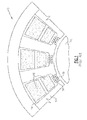
- a known permanent magnet machine 10 is provided with flux regulation and includes tooth pieces 12 defining intermediate slots or spaces 14, which receive main stator windings 16. Flux diverters 18 close off the spaces 14, and receive control coils 19. The control coils 19 control the flux at the main stator windings 16. Generally, if no control current is supplied to the control coils 19, a reluctance of the magnetic shunt provided by the flux diverters 18 is low because its magnetic permeability is high. Almost the total air gap magnetic flux produced by permanent magnets in an associated rotor 11 goes through the flux diverters 18. EMF induced in the main stator windings 16 is almost zero because the magnetic flux linked with the main stator windings 16 is very small.
- the magnetic flux diverters 18 partially saturate, and their magnetic permeability decreases. Reluctance increases, and only a portion of the magnetic flux is shunted by the flux diverters 18. The magnetic flux linked with the main stator winding 16 increases, as does the EMF induced in the main stator windings 16.
- a further increase in the control current further reduces the flux diverter reluctance, and its relative permeability becomes close to unity.
- a fully saturated flux diverter behaves as a free space, and almost the whole air gap magnetic flux excited by the rotor permanent magnets penetrates through the stator teeth 12 and excites a maximum EMF in the main stator windings 16.
- the benefits of such a system are known, as are the techniques for providing such control.
- the current in the control coils 19 is controlled to control the EMF and magnetic flux transmitted to the main stator windings 16 by the permanent magnets in the rotor 11.
- a method of forming a flux regulated machine includes winding stator windings into slots in an outer core.
- the outer core is formed to have a plurality of radially inwardly extending tooth pieces that are circumferentially spaced, and which define the slots. Further, control coils are wound around an inner core, Then, the inner core is inserted within the outer core such that the tooth pieces contact the inner core, and such that the control coils close off the slots at a radially innermost position.
- a flux regulated permanent magnet machine generally made according to this method is also disclosed.
- a flux regulated machine as described above with regard to Figure 1 is constructed in embodiments by utilizing an outer core and an inner core,
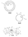
- the outer core 124 has a plurality of slots 126 formed by teeth or tooth pieces 128.
- the radially innermost edges or surfaces of the tooth pieces 128 may be angled.
- this application means that the surfaces are not perpendicular or tangent to a radius extending through the tooth piece. Further, one can see that between the edges 130 and 132, the angles are in generally opposed directions.
- Figure 2B shows an inner core 134.
- Inner core 134 has radially inner teeth 138 and intermediate slots 136. Slots 136 are at the same location as outer slots 140. As shown at 142 and 144, outer teeth on the radially outer side are formed at an angle which will generally correspond to the diverse angles of edges 130 and 132 of Figure 2A .
- a stator outer core subassembly 150 utilizes the outer core 124, and provides main stator windings 152 and 154 within the slots 126.
- the outer core 124 can be formed of laminations, stamped or laser cut, and stacked. That is, generally, the outer core 124 and inner core 134 are formed by thin metal elements, that are stacked together to form an elongate stator core component.
- the windings 152 and 154 can be easily deposited within the slots 126.
- the outer core 124 is furnished with a typical three-phase winding distributed into the slots 126 in one or two layers. Two layers are shown. Other core winding arrangements can be utilized.
- control coils 162 can be wound within the slots 136 and 140 on the inner core 134 to form a stator inner core subassembly 160.
- the slots 136/140 form the flux diverters. This is shown in Figure 3B .
- the inner core 134 is inserted within the outer core 124 to form the stator 170 as shown in Figure 3C .
- the inner core 134 may be force-fit within the outer core 124 to hold the two.
- the inner core 134 is positioned such that the control coils 162 extend across and close off the open slots 126.
- the mating faces 130/142 and 144/132 provide anti-rotation mating surfaces forming an anti-rotation structure.
- a stator 170 is provided that includes the complex winding arrangement with both the main stator windings and control coils, along with the flux diverters.
- the assembly is relatively simple, and does not require winding around the complex surface of the final product.
- a standard permanent magnet rotor 15 may be inserted into the stator 170 after assembly to form a flux regulated machine.
- FIG 4 shows an alternative embodiment 20, wherein main stator windings 32 are provided in slots 30 on an outer core 24, and control coils 38 are provided on an inner core 36.
- Flux diverters 26 are provided as in the prior embodiment.
- notches 42 are provided in the inner core 36 and pins 40 extend from the tooth piece 28 to provide the anti-rotation structure.
- the pins 40 and notches 42 can be located at alternate positions, such as providing pins 40 on inner core 36 and notches 42 on tooth pieces 28.
- control coil to control the main stator windings as set forth above with regard to Figure 1 , would also be true of the machines as shown in Figures 3C and 4 .
- the use of the inner core an outer core allows the selection of different magnetic materials. That is, since the two cores are associated with distinct magnetic functions, there may be benefits in selecting distinct materials for the two cores having different saturation flux densities to obtain faster saturation effects at a lower control current.
- the outer core may be fabricated using Hiperco-50 laminations, while the inner core could be fabricated using M-19 laminations. Of course, other materials may also be considered and used.
- Standard stator liners can be used to insulate the stator slots.
- the inner core may be insulted using powder coating techniques. As an example, the part may be immersed into a fluidized bed of coating powder where plastic powder is melted onto the inner core. The control coils may then be wound.
Landscapes
- Engineering & Computer Science (AREA)
- Power Engineering (AREA)
- Iron Core Of Rotating Electric Machines (AREA)
Abstract
Description
- This application relates to a method and apparatus for providing a flux regulated permanent magnet machine, wherein the stator is constructed of two separate cores.
- Recently, flux regulated permanent magnet machines have been proposed. In general, these machines have outer slots formed between tooth pieces. Main stator windings are received in the slots. An inner flux diverter closes off the slots, and receives a control coil.
- As shown in
Figure 1 , a knownpermanent magnet machine 10 is provided with flux regulation and includestooth pieces 12 defining intermediate slots or spaces 14, which receivemain stator windings 16. Flux diverters 18 close off the spaces 14, and receivecontrol coils 19. The control coils 19 control the flux at themain stator windings 16. Generally, if no control current is supplied to thecontrol coils 19, a reluctance of the magnetic shunt provided by theflux diverters 18 is low because its magnetic permeability is high. Almost the total air gap magnetic flux produced by permanent magnets in an associated rotor 11 goes through theflux diverters 18. EMF induced in themain stator windings 16 is almost zero because the magnetic flux linked with themain stator windings 16 is very small. - If the control current is increased above zero, then the magnetic flux diverters 18 partially saturate, and their magnetic permeability decreases. Reluctance increases, and only a portion of the magnetic flux is shunted by the
flux diverters 18. The magnetic flux linked with the main stator winding 16 increases, as does the EMF induced in themain stator windings 16. - A further increase in the control current further reduces the flux diverter reluctance, and its relative permeability becomes close to unity. A fully saturated flux diverter behaves as a free space, and almost the whole air gap magnetic flux excited by the rotor permanent magnets penetrates through the
stator teeth 12 and excites a maximum EMF in themain stator windings 16. The benefits of such a system are known, as are the techniques for providing such control. Generally, the current in thecontrol coils 19 is controlled to control the EMF and magnetic flux transmitted to themain stator windings 16 by the permanent magnets in the rotor 11. - However, challenges are raised to provide the stator, particularly in production quantities, given the location of the flux diverter 18 closing off the slot 14.
- A method of forming a flux regulated machine includes winding stator windings into slots in an outer core. The outer core is formed to have a plurality of radially inwardly extending tooth pieces that are circumferentially spaced, and which define the slots. Further, control coils are wound around an inner core, Then, the inner core is inserted within the outer core such that the tooth pieces contact the inner core, and such that the control coils close off the slots at a radially innermost position. A flux regulated permanent magnet machine generally made according to this method is also disclosed.
- These and other features of the present invention can be best understood from the following specification and drawings, of which the following is a brief description.
-
-
Figure 1 shows a prior art construction, -
Figure 2A shows a first component for making an embodiment of this invention. -
Figure 2B shows a second component. -
Figure 3A shows a step in creating the first embodiment invention. -
Figure 3B shows another step. -
Figure 3C shows a subsequent step. -
Figure 4 shows an alternative embodiment. - A flux regulated machine as described above with regard to
Figure 1 is constructed in embodiments by utilizing an outer core and an inner core, - As shown in
Figure 2A theouter core 124 has a plurality ofslots 126 formed by teeth ortooth pieces 128. As shown at 130 and 132, the radially innermost edges or surfaces of thetooth pieces 128 may be angled. By "angled," this application means that the surfaces are not perpendicular or tangent to a radius extending through the tooth piece. Further, one can see that between theedges -
Figure 2B shows aninner core 134.Inner core 134 has radiallyinner teeth 138 andintermediate slots 136.Slots 136 are at the same location asouter slots 140. As shown at 142 and 144, outer teeth on the radially outer side are formed at an angle which will generally correspond to the diverse angles ofedges Figure 2A . - As shown in
Figure 3A , a statorouter core subassembly 150 utilizes theouter core 124, and providesmain stator windings slots 126. Theouter core 124 can be formed of laminations, stamped or laser cut, and stacked. That is, generally, theouter core 124 andinner core 134 are formed by thin metal elements, that are stacked together to form an elongate stator core component. - By utilizing the
open slots 126, thewindings slots 126. - The
outer core 124 is furnished with a typical three-phase winding distributed into theslots 126 in one or two layers. Two layers are shown. Other core winding arrangements can be utilized. - Similarly, the
control coils 162 can be wound within theslots inner core 134 to form a statorinner core subassembly 160. Theslots 136/140 form the flux diverters. This is shown inFigure 3B . - After the steps of
Figures 3A and 3B , theinner core 134 is inserted within theouter core 124 to form thestator 170 as shown inFigure 3C . Theinner core 134 may be force-fit within theouter core 124 to hold the two. As can be appreciated, theinner core 134 is positioned such that thecontrol coils 162 extend across and close off theopen slots 126. - The mating faces 130/142 and 144/132 provide anti-rotation mating surfaces forming an anti-rotation structure.
- A
stator 170 is provided that includes the complex winding arrangement with both the main stator windings and control coils, along with the flux diverters. However, the assembly is relatively simple, and does not require winding around the complex surface of the final product. - As show in
Figure 3C , a standardpermanent magnet rotor 15 may be inserted into thestator 170 after assembly to form a flux regulated machine. -
Figure 4 shows analternative embodiment 20, whereinmain stator windings 32 are provided inslots 30 on anouter core 24, andcontrol coils 38 are provided on aninner core 36. Flux diverters 26 are provided as in the prior embodiment. In this embodiment,notches 42 are provided in theinner core 36 andpins 40 extend from thetooth piece 28 to provide the anti-rotation structure. As will be appreciated, thepins 40 andnotches 42 can be located at alternate positions, such as providingpins 40 oninner core 36 andnotches 42 ontooth pieces 28. - The function of the control coil to control the main stator windings as set forth above with regard to
Figure 1 , would also be true of the machines as shown inFigures 3C and4 . - The use of the disclosed two-part assembly actually allows standard stators for non-flux regulated machines to be utilized for the outer cores. Pole pieces are provided in prior art stators, and the use of the outer cores with inner cores will allow the use of those existing products.
- In addition, the use of the inner core an outer core allows the selection of different magnetic materials. That is, since the two cores are associated with distinct magnetic functions, there may be benefits in selecting distinct materials for the two cores having different saturation flux densities to obtain faster saturation effects at a lower control current. As one example, the outer core may be fabricated using Hiperco-50 laminations, while the inner core could be fabricated using M-19 laminations. Of course, other materials may also be considered and used.
- Standard stator liners can be used to insulate the stator slots. The inner core may be insulted using powder coating techniques. As an example, the part may be immersed into a fluidized bed of coating powder where plastic powder is melted onto the inner core. The control coils may then be wound.
- Although embodiments of this invention have been disclosed, a worker of ordinary skill in the art would recognize that certain modifications would come within the scope of this invention, which is defined by the following claims.
Claims (11)
- A method of forming a flux regulated machine comprising the steps of:winding stator windings (152, 154) into slots (126) in an outer core (124) having a plurality of radially inwardly extending tooth pieces that are circumferentially spaced, and which define the slots;winding control coils around an inner core (134); andinserting said inner core within said outer core such that said toot pieces contact said inner core, and such that said control coils extend circumferentially across said slots to close the slots.
- The method of as set forth in claim 1, including the step of preventing rotation between said inner core and said outer core.
- The method as set forth in claim 1, wherein said inner core and said outer core are formed of distinct magnetic materials.
- A flux regulated permanent magnet machine comprising:an outer core (124) having a plurality of radially inwardly extending toot pieces (128) defining slots (126) between adjacent tooth pieces;three-phase main stator windings (152, 154) received within said slots;a separate inner core (134) positioned radially within said outer core, and said tooth pieces contacting said inner core, said inner core having portions extending circumferentially across radially inner extents of said slots and control coils formed on said inner core at the portions; andan anti-rotation structure (130/142, 144/132) formed between said outer core and said inner core.
- The machine as set forth in claim 4, wherein said anti-rotation structure is found on each of said tooth pieces and corresponding locations on said inner core.
- The machine as set forth in claim 4, wherein said tooth pieces have radially innermost surfaces (130, 132) which are at an angle that is non-perpendicular to a radial direction through the tooth piece, said inner core having mating surfaces.
- The machine as set forth in claim 6, wherein there are distinct angles across the plurality of tooth pieces and the inner core.
- The machine as set forth in claim 7, wherein there are opposed angles on said tooth pieces and said inner core.
- The machine as set forth in claim 4, wherein one of said tooth pieces and said inner core have pins (40) extending into notches (42) in the other of said tooth pieces and said inner core.
- The machine as set forth in claim 9, wherein said tooth pieces have said pins (40) extending into notches (42) in the inner core.
- The machine as set forth in claim 4, wherein said inner core and said outer core are formed of distinct magnetic materials.
Applications Claiming Priority (1)
| Application Number | Priority Date | Filing Date | Title |
|---|---|---|---|
| US13/236,778 US8390164B1 (en) | 2011-09-20 | 2011-09-20 | Method of fabrication of permanent magnet machines with magnetic flux regulation |
Publications (3)
| Publication Number | Publication Date |
|---|---|
| EP2573907A2 true EP2573907A2 (en) | 2013-03-27 |
| EP2573907A3 EP2573907A3 (en) | 2016-06-15 |
| EP2573907B1 EP2573907B1 (en) | 2020-10-28 |
Family
ID=46801367
Family Applications (1)
| Application Number | Title | Priority Date | Filing Date |
|---|---|---|---|
| EP12183911.2A Active EP2573907B1 (en) | 2011-09-20 | 2012-09-11 | Method of fabrication of permanent magnet machines with magnetic flux regulation |
Country Status (2)
| Country | Link |
|---|---|
| US (1) | US8390164B1 (en) |
| EP (1) | EP2573907B1 (en) |
Cited By (2)
| Publication number | Priority date | Publication date | Assignee | Title |
|---|---|---|---|---|
| WO2019100038A1 (en) * | 2017-11-20 | 2019-05-23 | Borgwarner Inc. | Stator core and stator slot closer |
| EP2866343B1 (en) * | 2013-10-21 | 2019-06-26 | Pfeiffer Vacuum Gmbh | Vacuum pump |
Families Citing this family (3)
| Publication number | Priority date | Publication date | Assignee | Title |
|---|---|---|---|---|
| CN104184227B (en) * | 2014-06-26 | 2016-07-06 | 湖北特众电机有限公司 | Concentric partition type stator and stator winding concentrate assembling method |
| US10787967B2 (en) | 2014-08-12 | 2020-09-29 | Hamilton Sundstrand Corporation | Starter-generator modules for gas turbine engines |
| EP4459841A4 (en) * | 2021-12-27 | 2025-12-10 | Nidec Corp | STATOR CORE, STATOR, METHOD FOR MANUFACTURING THE STATOR CORE AND METHOD FOR MANUFACTURING THE STATOR |
Family Cites Families (17)
| Publication number | Priority date | Publication date | Assignee | Title |
|---|---|---|---|---|
| US4942493A (en) | 1988-11-02 | 1990-07-17 | Sundstrand Corporation | Method and apparatus for detecting prime mover start malfunction |
| US5055764A (en) | 1989-12-11 | 1991-10-08 | Sundstrand Corporation | Low voltage aircraft engine starting system |
| US6800977B1 (en) | 1997-12-23 | 2004-10-05 | Ford Global Technologies, Llc. | Field control in permanent magnet machine |
| DE19914943C1 (en) | 1999-04-01 | 2000-08-24 | Daimler Chrysler Ag | Reluctance motor includes internal C-ring, exerting outward radial force to keep especially large coils on stator poles, in rapidly- and simply manufactured design developing more torque, with no efficiency loss |
| US6208110B1 (en) | 1999-10-01 | 2001-03-27 | General Motors Corporation | Method for determining rotor position |
| DE69908786T2 (en) | 1999-12-15 | 2004-04-22 | Bien-Air Holding S.A. | Brushless motor with device for determining the rotor position |
| JP2002354768A (en) | 2001-05-24 | 2002-12-06 | Sankyo Seiki Mfg Co Ltd | Motor |
| JP2003052139A (en) * | 2001-08-07 | 2003-02-21 | Hitachi Ltd | Iron core, rotating electric machine using the same, and method of manufacturing the same |
| US6515396B1 (en) * | 2001-11-27 | 2003-02-04 | General Electric Company | Stator flux ring having fastenable pole pieces and method of making same |
| DE10236942A1 (en) * | 2002-08-12 | 2004-03-04 | Siemens Ag | Plate packet for electrical machine, especially for synchronous machine stator, has yoke plate packet with radially inward-facing pole teeth, each pole head radially bounding on relevant pole tooth |
| JP4691376B2 (en) * | 2005-03-25 | 2011-06-01 | 山洋電気株式会社 | Permanent magnet type rotary motor |
| US7439713B2 (en) * | 2006-09-20 | 2008-10-21 | Pratt & Whitney Canada Corp. | Modulation control of power generation system |
| US7859231B2 (en) | 2008-04-02 | 2010-12-28 | Hamilton Sundstrand Corporation | Permanent magnet electric generator with variable magnet flux excitation |
| US7777384B2 (en) | 2008-04-02 | 2010-08-17 | Hamilton Sundstrand Corporation | Permanent magnet dynamoelectric machine with variable magnetic flux excitation |
| US7843155B2 (en) * | 2008-04-10 | 2010-11-30 | Hamilton Sundstrand Corporation | Direct flux regulated permanent magnet brushless motor utilizing sensorless control |
| US8080960B2 (en) * | 2008-08-20 | 2011-12-20 | Hamilton Sundstrand Corporation | Direct flux regulated permanent magnet brushless motor utilizing sensorless control by DC and AC excitation |
| US8410656B2 (en) * | 2009-10-30 | 2013-04-02 | General Electric Company | Segmented stator assembly |
-
2011
- 2011-09-20 US US13/236,778 patent/US8390164B1/en active Active
-
2012
- 2012-09-11 EP EP12183911.2A patent/EP2573907B1/en active Active
Non-Patent Citations (1)
| Title |
|---|
| None |
Cited By (2)
| Publication number | Priority date | Publication date | Assignee | Title |
|---|---|---|---|---|
| EP2866343B1 (en) * | 2013-10-21 | 2019-06-26 | Pfeiffer Vacuum Gmbh | Vacuum pump |
| WO2019100038A1 (en) * | 2017-11-20 | 2019-05-23 | Borgwarner Inc. | Stator core and stator slot closer |
Also Published As
| Publication number | Publication date |
|---|---|
| EP2573907A3 (en) | 2016-06-15 |
| US20130069477A1 (en) | 2013-03-21 |
| US8390164B1 (en) | 2013-03-05 |
| EP2573907B1 (en) | 2020-10-28 |
Similar Documents
| Publication | Publication Date | Title |
|---|---|---|
| EP3457534B1 (en) | Rotating electric machine | |
| EP2504904B1 (en) | Coil tooth assembly | |
| US8129880B2 (en) | Concentrated winding machine with magnetic slot wedges | |
| US9287742B2 (en) | Spoke permanent magnet machine with reduced torque ripple and method of manufacturing thereof | |
| EP2159903A2 (en) | Transverse flux machine | |
| EP2573907B1 (en) | Method of fabrication of permanent magnet machines with magnetic flux regulation | |
| US9887608B2 (en) | Rotor, stator and motor | |
| EP2228892A2 (en) | An electrical machine with dual radial airgaps | |
| US20170163106A1 (en) | Rotor for a reluctance machine | |
| EP2237390A2 (en) | Electric machine | |
| CN104426277A (en) | Coil insulating structure of electromagnetic motor stator | |
| CN106716781B (en) | Electric machines with low slot leakage | |
| KR100432954B1 (en) | Brushless Direct Current Motor of Radial Core Type Having a Structure of Double Rotors | |
| CN104426315A (en) | Three-phase electromagnetic motor | |
| US20150247530A1 (en) | Active part of an electrical machine, radial magnetic bearing and method for producing a radial magnetic bearing | |
| JP2017169419A (en) | Stator of rotary electric machine | |
| EP3154154B1 (en) | Electric machine stator lamination with dual phase magnetic material | |
| US20080282531A1 (en) | Concentrated winding machine with magnetic slot wedges | |
| KR20190120242A (en) | Stator assembly with heat recovery for electrical machines | |
| EP2712056A2 (en) | Stator and rotating electrical machine | |
| EP0976192B1 (en) | Procedure for preparing and fitting the windings for an electric motor | |
| CN208835970U (en) | Single-phase permanent magnet motor | |
| JP4400283B2 (en) | Stator teeth structure of an axial gap type rotating electrical machine | |
| JP2009027849A (en) | Permanent magnet rotating electric machine | |
| US20120112598A1 (en) | Electrical machine stator assembly |
Legal Events
| Date | Code | Title | Description |
|---|---|---|---|
| PUAI | Public reference made under article 153(3) epc to a published international application that has entered the european phase |
Free format text: ORIGINAL CODE: 0009012 |
|
| AK | Designated contracting states |
Kind code of ref document: A2 Designated state(s): AL AT BE BG CH CY CZ DE DK EE ES FI FR GB GR HR HU IE IS IT LI LT LU LV MC MK MT NL NO PL PT RO RS SE SI SK SM TR |
|
| AX | Request for extension of the european patent |
Extension state: BA ME |
|
| PUAL | Search report despatched |
Free format text: ORIGINAL CODE: 0009013 |
|
| AK | Designated contracting states |
Kind code of ref document: A3 Designated state(s): AL AT BE BG CH CY CZ DE DK EE ES FI FR GB GR HR HU IE IS IT LI LT LU LV MC MK MT NL NO PL PT RO RS SE SI SK SM TR |
|
| AX | Request for extension of the european patent |
Extension state: BA ME |
|
| RIC1 | Information provided on ipc code assigned before grant |
Ipc: H02K 21/14 20060101ALN20160509BHEP Ipc: H02K 3/493 20060101ALI20160509BHEP Ipc: H02K 3/16 20060101AFI20160509BHEP |
|
| STAA | Information on the status of an ep patent application or granted ep patent |
Free format text: STATUS: REQUEST FOR EXAMINATION WAS MADE |
|
| 17P | Request for examination filed |
Effective date: 20161214 |
|
| RBV | Designated contracting states (corrected) |
Designated state(s): AL AT BE BG CH CY CZ DE DK EE ES FI FR GB GR HR HU IE IS IT LI LT LU LV MC MK MT NL NO PL PT RO RS SE SI SK SM TR |
|
| STAA | Information on the status of an ep patent application or granted ep patent |
Free format text: STATUS: EXAMINATION IS IN PROGRESS |
|
| 17Q | First examination report despatched |
Effective date: 20171218 |
|
| GRAP | Despatch of communication of intention to grant a patent |
Free format text: ORIGINAL CODE: EPIDOSNIGR1 |
|
| STAA | Information on the status of an ep patent application or granted ep patent |
Free format text: STATUS: GRANT OF PATENT IS INTENDED |
|
| RIC1 | Information provided on ipc code assigned before grant |
Ipc: H02K 21/14 20060101ALN20200423BHEP Ipc: H02K 3/493 20060101ALI20200423BHEP Ipc: H02K 3/16 20060101AFI20200423BHEP |
|
| INTG | Intention to grant announced |
Effective date: 20200519 |
|
| RAP1 | Party data changed (applicant data changed or rights of an application transferred) |
Owner name: HAMILTON SUNDSTRAND CORPORATION |
|
| GRAS | Grant fee paid |
Free format text: ORIGINAL CODE: EPIDOSNIGR3 |
|
| GRAA | (expected) grant |
Free format text: ORIGINAL CODE: 0009210 |
|
| STAA | Information on the status of an ep patent application or granted ep patent |
Free format text: STATUS: THE PATENT HAS BEEN GRANTED |
|
| AK | Designated contracting states |
Kind code of ref document: B1 Designated state(s): AL AT BE BG CH CY CZ DE DK EE ES FI FR GB GR HR HU IE IS IT LI LT LU LV MC MK MT NL NO PL PT RO RS SE SI SK SM TR |
|
| REG | Reference to a national code |
Ref country code: GB Ref legal event code: FG4D |
|
| REG | Reference to a national code |
Ref country code: CH Ref legal event code: EP |
|
| REG | Reference to a national code |
Ref country code: AT Ref legal event code: REF Ref document number: 1329220 Country of ref document: AT Kind code of ref document: T Effective date: 20201115 |
|
| REG | Reference to a national code |
Ref country code: DE Ref legal event code: R096 Ref document number: 602012072964 Country of ref document: DE |
|
| REG | Reference to a national code |
Ref country code: IE Ref legal event code: FG4D |
|
| REG | Reference to a national code |
Ref country code: AT Ref legal event code: MK05 Ref document number: 1329220 Country of ref document: AT Kind code of ref document: T Effective date: 20201028 |
|
| REG | Reference to a national code |
Ref country code: NL Ref legal event code: MP Effective date: 20201028 |
|
| PG25 | Lapsed in a contracting state [announced via postgrant information from national office to epo] |
Ref country code: NO Free format text: LAPSE BECAUSE OF FAILURE TO SUBMIT A TRANSLATION OF THE DESCRIPTION OR TO PAY THE FEE WITHIN THE PRESCRIBED TIME-LIMIT Effective date: 20210128 Ref country code: NL Free format text: LAPSE BECAUSE OF FAILURE TO SUBMIT A TRANSLATION OF THE DESCRIPTION OR TO PAY THE FEE WITHIN THE PRESCRIBED TIME-LIMIT Effective date: 20201028 Ref country code: PT Free format text: LAPSE BECAUSE OF FAILURE TO SUBMIT A TRANSLATION OF THE DESCRIPTION OR TO PAY THE FEE WITHIN THE PRESCRIBED TIME-LIMIT Effective date: 20210301 Ref country code: FI Free format text: LAPSE BECAUSE OF FAILURE TO SUBMIT A TRANSLATION OF THE DESCRIPTION OR TO PAY THE FEE WITHIN THE PRESCRIBED TIME-LIMIT Effective date: 20201028 Ref country code: RS Free format text: LAPSE BECAUSE OF FAILURE TO SUBMIT A TRANSLATION OF THE DESCRIPTION OR TO PAY THE FEE WITHIN THE PRESCRIBED TIME-LIMIT Effective date: 20201028 Ref country code: GR Free format text: LAPSE BECAUSE OF FAILURE TO SUBMIT A TRANSLATION OF THE DESCRIPTION OR TO PAY THE FEE WITHIN THE PRESCRIBED TIME-LIMIT Effective date: 20210129 |
|
| REG | Reference to a national code |
Ref country code: LT Ref legal event code: MG4D |
|
| PG25 | Lapsed in a contracting state [announced via postgrant information from national office to epo] |
Ref country code: PL Free format text: LAPSE BECAUSE OF FAILURE TO SUBMIT A TRANSLATION OF THE DESCRIPTION OR TO PAY THE FEE WITHIN THE PRESCRIBED TIME-LIMIT Effective date: 20201028 Ref country code: LV Free format text: LAPSE BECAUSE OF FAILURE TO SUBMIT A TRANSLATION OF THE DESCRIPTION OR TO PAY THE FEE WITHIN THE PRESCRIBED TIME-LIMIT Effective date: 20201028 Ref country code: SE Free format text: LAPSE BECAUSE OF FAILURE TO SUBMIT A TRANSLATION OF THE DESCRIPTION OR TO PAY THE FEE WITHIN THE PRESCRIBED TIME-LIMIT Effective date: 20201028 Ref country code: BG Free format text: LAPSE BECAUSE OF FAILURE TO SUBMIT A TRANSLATION OF THE DESCRIPTION OR TO PAY THE FEE WITHIN THE PRESCRIBED TIME-LIMIT Effective date: 20210128 Ref country code: AT Free format text: LAPSE BECAUSE OF FAILURE TO SUBMIT A TRANSLATION OF THE DESCRIPTION OR TO PAY THE FEE WITHIN THE PRESCRIBED TIME-LIMIT Effective date: 20201028 Ref country code: ES Free format text: LAPSE BECAUSE OF FAILURE TO SUBMIT A TRANSLATION OF THE DESCRIPTION OR TO PAY THE FEE WITHIN THE PRESCRIBED TIME-LIMIT Effective date: 20201028 Ref country code: IS Free format text: LAPSE BECAUSE OF FAILURE TO SUBMIT A TRANSLATION OF THE DESCRIPTION OR TO PAY THE FEE WITHIN THE PRESCRIBED TIME-LIMIT Effective date: 20210228 |
|
| PG25 | Lapsed in a contracting state [announced via postgrant information from national office to epo] |
Ref country code: HR Free format text: LAPSE BECAUSE OF FAILURE TO SUBMIT A TRANSLATION OF THE DESCRIPTION OR TO PAY THE FEE WITHIN THE PRESCRIBED TIME-LIMIT Effective date: 20201028 |
|
| REG | Reference to a national code |
Ref country code: DE Ref legal event code: R097 Ref document number: 602012072964 Country of ref document: DE |
|
| PG25 | Lapsed in a contracting state [announced via postgrant information from national office to epo] |
Ref country code: SM Free format text: LAPSE BECAUSE OF FAILURE TO SUBMIT A TRANSLATION OF THE DESCRIPTION OR TO PAY THE FEE WITHIN THE PRESCRIBED TIME-LIMIT Effective date: 20201028 Ref country code: EE Free format text: LAPSE BECAUSE OF FAILURE TO SUBMIT A TRANSLATION OF THE DESCRIPTION OR TO PAY THE FEE WITHIN THE PRESCRIBED TIME-LIMIT Effective date: 20201028 Ref country code: CZ Free format text: LAPSE BECAUSE OF FAILURE TO SUBMIT A TRANSLATION OF THE DESCRIPTION OR TO PAY THE FEE WITHIN THE PRESCRIBED TIME-LIMIT Effective date: 20201028 Ref country code: RO Free format text: LAPSE BECAUSE OF FAILURE TO SUBMIT A TRANSLATION OF THE DESCRIPTION OR TO PAY THE FEE WITHIN THE PRESCRIBED TIME-LIMIT Effective date: 20201028 Ref country code: SK Free format text: LAPSE BECAUSE OF FAILURE TO SUBMIT A TRANSLATION OF THE DESCRIPTION OR TO PAY THE FEE WITHIN THE PRESCRIBED TIME-LIMIT Effective date: 20201028 Ref country code: LT Free format text: LAPSE BECAUSE OF FAILURE TO SUBMIT A TRANSLATION OF THE DESCRIPTION OR TO PAY THE FEE WITHIN THE PRESCRIBED TIME-LIMIT Effective date: 20201028 |
|
| PG25 | Lapsed in a contracting state [announced via postgrant information from national office to epo] |
Ref country code: DK Free format text: LAPSE BECAUSE OF FAILURE TO SUBMIT A TRANSLATION OF THE DESCRIPTION OR TO PAY THE FEE WITHIN THE PRESCRIBED TIME-LIMIT Effective date: 20201028 |
|
| PLBE | No opposition filed within time limit |
Free format text: ORIGINAL CODE: 0009261 |
|
| STAA | Information on the status of an ep patent application or granted ep patent |
Free format text: STATUS: NO OPPOSITION FILED WITHIN TIME LIMIT |
|
| 26N | No opposition filed |
Effective date: 20210729 |
|
| PG25 | Lapsed in a contracting state [announced via postgrant information from national office to epo] |
Ref country code: AL Free format text: LAPSE BECAUSE OF FAILURE TO SUBMIT A TRANSLATION OF THE DESCRIPTION OR TO PAY THE FEE WITHIN THE PRESCRIBED TIME-LIMIT Effective date: 20201028 Ref country code: IT Free format text: LAPSE BECAUSE OF FAILURE TO SUBMIT A TRANSLATION OF THE DESCRIPTION OR TO PAY THE FEE WITHIN THE PRESCRIBED TIME-LIMIT Effective date: 20201028 |
|
| PG25 | Lapsed in a contracting state [announced via postgrant information from national office to epo] |
Ref country code: SI Free format text: LAPSE BECAUSE OF FAILURE TO SUBMIT A TRANSLATION OF THE DESCRIPTION OR TO PAY THE FEE WITHIN THE PRESCRIBED TIME-LIMIT Effective date: 20201028 |
|
| REG | Reference to a national code |
Ref country code: DE Ref legal event code: R119 Ref document number: 602012072964 Country of ref document: DE |
|
| REG | Reference to a national code |
Ref country code: CH Ref legal event code: PL |
|
| REG | Reference to a national code |
Ref country code: BE Ref legal event code: MM Effective date: 20210930 |
|
| PG25 | Lapsed in a contracting state [announced via postgrant information from national office to epo] |
Ref country code: IS Free format text: LAPSE BECAUSE OF FAILURE TO SUBMIT A TRANSLATION OF THE DESCRIPTION OR TO PAY THE FEE WITHIN THE PRESCRIBED TIME-LIMIT Effective date: 20210228 Ref country code: MC Free format text: LAPSE BECAUSE OF FAILURE TO SUBMIT A TRANSLATION OF THE DESCRIPTION OR TO PAY THE FEE WITHIN THE PRESCRIBED TIME-LIMIT Effective date: 20201028 |
|
| PG25 | Lapsed in a contracting state [announced via postgrant information from national office to epo] |
Ref country code: LU Free format text: LAPSE BECAUSE OF NON-PAYMENT OF DUE FEES Effective date: 20210911 Ref country code: IE Free format text: LAPSE BECAUSE OF NON-PAYMENT OF DUE FEES Effective date: 20210911 Ref country code: DE Free format text: LAPSE BECAUSE OF NON-PAYMENT OF DUE FEES Effective date: 20220401 Ref country code: BE Free format text: LAPSE BECAUSE OF NON-PAYMENT OF DUE FEES Effective date: 20210930 |
|
| PG25 | Lapsed in a contracting state [announced via postgrant information from national office to epo] |
Ref country code: LI Free format text: LAPSE BECAUSE OF NON-PAYMENT OF DUE FEES Effective date: 20210930 Ref country code: CH Free format text: LAPSE BECAUSE OF NON-PAYMENT OF DUE FEES Effective date: 20210930 |
|
| PG25 | Lapsed in a contracting state [announced via postgrant information from national office to epo] |
Ref country code: HU Free format text: LAPSE BECAUSE OF FAILURE TO SUBMIT A TRANSLATION OF THE DESCRIPTION OR TO PAY THE FEE WITHIN THE PRESCRIBED TIME-LIMIT; INVALID AB INITIO Effective date: 20120911 Ref country code: CY Free format text: LAPSE BECAUSE OF FAILURE TO SUBMIT A TRANSLATION OF THE DESCRIPTION OR TO PAY THE FEE WITHIN THE PRESCRIBED TIME-LIMIT Effective date: 20201028 |
|
| P01 | Opt-out of the competence of the unified patent court (upc) registered |
Effective date: 20230522 |
|
| PG25 | Lapsed in a contracting state [announced via postgrant information from national office to epo] |
Ref country code: MK Free format text: LAPSE BECAUSE OF FAILURE TO SUBMIT A TRANSLATION OF THE DESCRIPTION OR TO PAY THE FEE WITHIN THE PRESCRIBED TIME-LIMIT Effective date: 20201028 |
|
| PG25 | Lapsed in a contracting state [announced via postgrant information from national office to epo] |
Ref country code: MT Free format text: LAPSE BECAUSE OF FAILURE TO SUBMIT A TRANSLATION OF THE DESCRIPTION OR TO PAY THE FEE WITHIN THE PRESCRIBED TIME-LIMIT Effective date: 20201028 |
|
| PGFP | Annual fee paid to national office [announced via postgrant information from national office to epo] |
Ref country code: GB Payment date: 20250822 Year of fee payment: 14 |
|
| PGFP | Annual fee paid to national office [announced via postgrant information from national office to epo] |
Ref country code: FR Payment date: 20250821 Year of fee payment: 14 |
|
| PG25 | Lapsed in a contracting state [announced via postgrant information from national office to epo] |
Ref country code: TR Free format text: LAPSE BECAUSE OF FAILURE TO SUBMIT A TRANSLATION OF THE DESCRIPTION OR TO PAY THE FEE WITHIN THE PRESCRIBED TIME-LIMIT Effective date: 20201028 |