EP2573893A2 - Electronic control unit for automobile - Google Patents
Electronic control unit for automobile Download PDFInfo
- Publication number
- EP2573893A2 EP2573893A2 EP20120180127 EP12180127A EP2573893A2 EP 2573893 A2 EP2573893 A2 EP 2573893A2 EP 20120180127 EP20120180127 EP 20120180127 EP 12180127 A EP12180127 A EP 12180127A EP 2573893 A2 EP2573893 A2 EP 2573893A2
- Authority
- EP
- European Patent Office
- Prior art keywords
- fet
- power supply
- voltage
- resistor
- control unit
- Prior art date
- Legal status (The legal status is an assumption and is not a legal conclusion. Google has not performed a legal analysis and makes no representation as to the accuracy of the status listed.)
- Withdrawn
Links
Images


Classifications
-
- H—ELECTRICITY
- H02—GENERATION; CONVERSION OR DISTRIBUTION OF ELECTRIC POWER
- H02H—EMERGENCY PROTECTIVE CIRCUIT ARRANGEMENTS
- H02H11/00—Emergency protective circuit arrangements for preventing the switching-on in case an undesired electric working condition might result
- H02H11/002—Emergency protective circuit arrangements for preventing the switching-on in case an undesired electric working condition might result in case of inverted polarity or connection; with switching for obtaining correct connection
- H02H11/003—Emergency protective circuit arrangements for preventing the switching-on in case an undesired electric working condition might result in case of inverted polarity or connection; with switching for obtaining correct connection using a field effect transistor as protecting element in one of the supply lines
-
- B—PERFORMING OPERATIONS; TRANSPORTING
- B60—VEHICLES IN GENERAL
- B60L—PROPULSION OF ELECTRICALLY-PROPELLED VEHICLES; SUPPLYING ELECTRIC POWER FOR AUXILIARY EQUIPMENT OF ELECTRICALLY-PROPELLED VEHICLES; ELECTRODYNAMIC BRAKE SYSTEMS FOR VEHICLES IN GENERAL; MAGNETIC SUSPENSION OR LEVITATION FOR VEHICLES; MONITORING OPERATING VARIABLES OF ELECTRICALLY-PROPELLED VEHICLES; ELECTRIC SAFETY DEVICES FOR ELECTRICALLY-PROPELLED VEHICLES
- B60L58/00—Methods or circuit arrangements for monitoring or controlling batteries or fuel cells, specially adapted for electric vehicles
- B60L58/10—Methods or circuit arrangements for monitoring or controlling batteries or fuel cells, specially adapted for electric vehicles for monitoring or controlling batteries
-
- H—ELECTRICITY
- H02—GENERATION; CONVERSION OR DISTRIBUTION OF ELECTRIC POWER
- H02J—ELECTRIC POWER NETWORKS; CIRCUIT ARRANGEMENTS OR SYSTEMS FOR SUPPLYING OR DISTRIBUTING ELECTRIC POWER; SYSTEMS FOR STORING ELECTRIC ENERGY
- H02J7/00—Circuit arrangements for charging or discharging batteries or for supplying loads from batteries
- H02J7/60—Circuit arrangements for charging or discharging batteries or for supplying loads from batteries including safety or protection arrangements
- H02J7/68—Circuit arrangements for charging or discharging batteries or for supplying loads from batteries including safety or protection arrangements using circuits for correcting or protecting against reverse-polarity
-
- H—ELECTRICITY
- H02—GENERATION; CONVERSION OR DISTRIBUTION OF ELECTRIC POWER
- H02H—EMERGENCY PROTECTIVE CIRCUIT ARRANGEMENTS
- H02H9/00—Emergency protective circuit arrangements for limiting excess current or voltage without disconnection
- H02H9/04—Emergency protective circuit arrangements for limiting excess current or voltage without disconnection responsive to excess voltage
- H02H9/041—Emergency protective circuit arrangements for limiting excess current or voltage without disconnection responsive to excess voltage using a short-circuiting device
-
- Y—GENERAL TAGGING OF NEW TECHNOLOGICAL DEVELOPMENTS; GENERAL TAGGING OF CROSS-SECTIONAL TECHNOLOGIES SPANNING OVER SEVERAL SECTIONS OF THE IPC; TECHNICAL SUBJECTS COVERED BY FORMER USPC CROSS-REFERENCE ART COLLECTIONS [XRACs] AND DIGESTS
- Y02—TECHNOLOGIES OR APPLICATIONS FOR MITIGATION OR ADAPTATION AGAINST CLIMATE CHANGE
- Y02T—CLIMATE CHANGE MITIGATION TECHNOLOGIES RELATED TO TRANSPORTATION
- Y02T10/00—Road transport of goods or passengers
- Y02T10/60—Other road transportation technologies with climate change mitigation effect
- Y02T10/70—Energy storage systems for electromobility, e.g. batteries
Definitions
- the present invention relates to an electronic control unit for automobile and, more particularly, to a circuit of a power supply input section to a power supply control IC of the electronic control unit for automobile.
- a method of connecting a diode to the power supply input section as the reverse polarity protection circuit has been used. If the battery is reversely connected, a path of an electric current flowing from a power supply control IC to the battery is cut off by a rectifying action of the diode. Therefore, a voltage applied to the power supply control IC drops to nearly 0 V.
- JP-A-7-244584 discloses a technology of a reverse polarity prevention circuit in which an MOSFET is used instead of the diode and a voltage drop does not occur.
- an electronic control unit for an automobile includes: a first FET connected between a vehicle-mounted battery and a power supply control IC that lowers an output voltage from the vehicle-mounted battery to a predetermined value; a second FET configured to control ON and OFF of the first FET; a first resistor connected in series between a gate of the second FET and a plus terminal of the vehicle-mounted battery; a first surge voltage protection element connected between the gate of the second FET and the ground; a coil connected in series between a source of the first FET and the power supply control IC; a second resistor connected between the source of the first FET and a drain of the second FET; a capacitor connected to an input side of the power supply control IC; a third resistor connected in series between a gate of the first FET and the second FET; and/or a second surge voltage protection element connected to the input side of the power supply control IC.
- the present invention even if the voltage of a battery mounted on a vehicle drops to near an operable voltage of the ECU, it is possible to guarantee the operation of the ECU. Even if battery terminals are reversely connected, it is possible to protect an ECU internal circuit. Further, it is possible to protect the ECU internal circuit and prevent ECU reset when a surge occurs.
- a revere polarity protection circuit in which a diode is used is explained with reference to Fig. 1 .
- a method of connecting the diode to a power supply input section of an ECU as shown in Fig. 1 even if a battery is reversely connected to the ECU, a path of an electric current flowing from a power supply control IC in the ECU to the battery is cut off by a rectifying action of the diode. Therefore, a voltage applied to the power supply control IC drops to nearly 0 V.
- the circuit shown in Fig. 1 is ideal as the reverse polarity protection circuit.
- a voltage drop equivalent to a forward voltage of the diode occurs.
- an operable voltage of the ECU e.g. 6 V
- the circuit shown in Fig. 2 includes an FET for reverse polarity protection mounted between an input terminal and an output terminal, an FET for switching that performs switching of the FET; a resistor and a diode mounted between the two FETs, and a resistor for dividing a gate voltage.
- an FET for reverse polarity protection mounted between an input terminal and an output terminal
- an FET for switching that performs switching of the FET
- a resistor and a diode mounted between the two FETs
- a resistor for dividing a gate voltage In such a configuration, when a surge occurs, the FET for switching is destroyed and an abnormal current flows from the input terminal.
- a zener diode is used for a gate of the FET for switching to prevent the FET from being destroyed when a surge occurs.
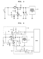
- Fig. 3 is a diagram of a reverse polarity protection circuit according to an embodiment of the present invention that can guarantee the operation of an ECU even if a battery voltage drops to about 6 V, which is an operable voltage of the ECU.
- the reverse polarity protection circuit includes a p-channel MOSFET 1, an n-channel MOSFET 2, a zener diode 3, a zener diode 4, a coil 5 that suppresses a backward flow of an electric current, a resistor 6 that retains a voltage difference between a source of the p-channel MOSFET 1 and a drain of the n-channel MOSFET 2, a resistor 7 that protects the circuit if short-circuit destruction of the p-channel MOSFET 1 occurs, a resistor 8 that protects the circuit if short-circuit destruction of the n-channel MOSFET 2 occurs, an electrolytic capacitor 9 that suppresses fluctuation in an input voltage to a power supply control IC 11, a battery 10 that supplies a voltage to the ECU, and the power supply control IC 11 that generates a voltage for causing an IC in the ECU to operate.
- a voltage is supplied to the power supply control IC 11 through a parasitic diode of the p-channel MOSFET 1.
- the n-channel MOSFET 2 is turned on and a gate of the p-channel MOSFET 1 is set to low, whereby a potential difference occurs between the gate and a source of the p-channel MOSFET 1. Since the p-channel MOSFET 1 is turned on, unlike the circuit shown in Fig. 1 , a voltage drop does not occur between the battery 10 and the power supply control IC 11. Therefore, it is possible to guarantee the operation of the ECU even if the voltage of the battery 10 drops to about an ECU operable voltage of 6 V.
- a gate voltage of the n-channel MOSFET 2 is fixed to a zener voltage by the zener diode 3. Therefore, the n-channel MOSFET 2 is protected. If a short-circuit failure of the n-channel MOSFET 2 is caused by the resistor 8, it is possible to realize prevention of a short circuit between the battery 10 and the ground. Further, since the zener diode 4 protects the power supply control IC 11, it is possible to continue the normal operation of the ECU.
- the n-channel MOSFET 2 is protected even when a surge occurs, a function of switching the gate of the p-channel MOSFET 1 is guaranteed. Consequently, an abnormal current can be prevented from flowing to the power supply control IC 11. Therefore, it is possible to guarantee the operation of the ECU even when a surge occurs.
- Fig. 4 is a diagram of a reverse polarity protection circuit according to a second embodiment in which a failure diagnostic function of the p-channel MOSFET 1 is provided.
- the reverse polarity protection circuit according to the second embodiment shown in Fig. 4 includes, in addition to the components of the circuit shown in Fig. 3 , a differential amplifying circuit 12 that detects a voltage difference between the source and a drain of the p-channel MOSFET 1, a differential amplifying circuit 13 that detects a potential difference of the resistor 7, a reference voltage 14 of the differential amplifying circuit 12, and an MPU 15.
- the voltage from the power supply control IC 11 may be supplied to the MPU 15.
- the ECU may function as both of an MPU that performs an arithmetic operation for controlling a control target apparatus and the MPU 15.
- an output A of the differential amplifying circuit 12 can be calculated as indicated by Expression (1) below.
- A ⁇ ⁇ Ron ⁇ Ids + X
- the output A of the differential amplifying circuit 12 is equal to the reference voltage X.
- the output A of the differential amplifying circuit 12 instantaneously decreases to be equal to or lower than the reference voltage X until the ECU returns to the normal operation.
- the output A of the differential amplifying circuit 12 can create a diagnostic map shown in Fig. 5 .
- the ordinate of Fig. 5 represents the output A of the differential amplifying circuit 12 and the abscissa of Fig. 5 represents the state change of the p-channel MOSFET 1.
- an output B of the differential amplifying circuit 13 is equal to an offset voltage of an operational amplifier.
- the output B of the differential amplifying circuit 13 can create a diagnostic map shown in Fig. 6 .
- the ordinate of Fig. 6 represents the output B of the differential amplifying circuit 13 and the abscissa of Fig. 6 represents the state change of the p-channel MOSFET 1.
- the MFP 15 can determine a failure of the p-channel MOSFET 1 by comparing the outputs A and B from the differential amplifying circuits 12 and 13 and the reference voltage 14, determination values stored in a ROM in the ECU in advance, and the like.
- the MPU 15 determines a failure of the p-channel MOSFET 1
- the MPU 15 outputs a signal from the ECU and turns on a warning lamp to inform a driver of abnormality and perform predetermined failsafe control.
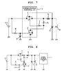
- Fig. 7 is a diagram of a reverse polarity protection circuit according to a third embodiment in which the p-channel MOSFET 1 and the n-channel MOSFET 2 shown in Fig. 3 are integrated in the power supply control IC 11 as one package. It is possible to reduce a mounting area by integrating the p-channel MOSFET 1 and the n-channel MOSFET 2 in the power supply control IC 11.
- the p-channel MOSFET 1 and the n-channel MOSFET 2 can be mounted as an ASIC as well.
- Fig. 8 is a diagram of a reverse polarity protection circuit according to a fourth embodiment in which a varistor 16 is used instead of the zener diode 3 shown in Fig. 3 .
- the varistor 16 has high electrical resistance when a voltage between both terminals is low and has low electrical resistance when the voltage between both the terminals is equal to or higher than a predetermined voltage. Therefore, even if the varistor 16 is used instead of the zener diode 3, when a surge occurs from the power supply input section of the battery 10, it is possible to protect a gate of the n-channel MOSFET 2.
- a varistor may be used instead of the zener diode 4.
Landscapes
- Engineering & Computer Science (AREA)
- Power Engineering (AREA)
- Life Sciences & Earth Sciences (AREA)
- Sustainable Development (AREA)
- Sustainable Energy (AREA)
- Transportation (AREA)
- Mechanical Engineering (AREA)
- Charge And Discharge Circuits For Batteries Or The Like (AREA)
- Protection Of Static Devices (AREA)
- Dc-Dc Converters (AREA)
- Emergency Protection Circuit Devices (AREA)
- Electronic Switches (AREA)
Abstract
Description
- The present invention relates to an electronic control unit for automobile and, more particularly, to a circuit of a power supply input section to a power supply control IC of the electronic control unit for automobile.
- In causing an electronic control unit for automobile (ECU) to operate, there is generally adopted a method of connecting a plus terminal of a battery and an ECU power supply input terminal and connecting a minus terminal of the battery to the GND to supply electric power to the ECU and cause the ECU to operate. However, it is likely that the terminals of the battery are reversely connected because of a human error. In the ECU in which measures against the reverse connection are not taken, an internal circuit is destroyed. Therefore, it is necessary to configure a reverse polarity protection circuit in an ECU power supply input section.
- A method of connecting a diode to the power supply input section as the reverse polarity protection circuit has been used. If the battery is reversely connected, a path of an electric current flowing from a power supply control IC to the battery is cut off by a rectifying action of the diode. Therefore, a voltage applied to the power supply control IC drops to nearly 0 V.
- However, in this system, if the battery is normally connected, a voltage drop equivalent to a forward voltage of the diode occurs. Therefore, when a battery voltage drops to, for example, about an operable voltage of the ECU, it is likely that a voltage for the ECU to operate is insufficient and ECU reset occurs.
-
JP-A-7-244584 - In the reverse polarity protection circuit in the past in which the diode is used, when the battery voltage drops, it is likely that a voltage necessary for the operation of the power supply control IC cannot be supplied and the ECU malfunctions. There is no conception and disclosure concerning protection of an FET in
JP-A-7-244584 JP-A-7-244584 - Therefore, it is an object of the present invention to provide a circuit configuration of a power supply input section in which a MOSFET is used instead of the diode and the MOSFET can be protected even when a surge occurs.
- According to an aspect of the present invention, an electronic control unit for an automobile includes: a first FET connected between a vehicle-mounted battery and a power supply control IC that lowers an output voltage from the vehicle-mounted battery to a predetermined value; a second FET configured to control ON and OFF of the first FET; a first resistor connected in series between a gate of the second FET and a plus terminal of the vehicle-mounted battery; a first surge voltage protection element connected between the gate of the second FET and the ground; a coil connected in series between a source of the first FET and the power supply control IC; a second resistor connected between the source of the first FET and a drain of the second FET; a capacitor connected to an input side of the power supply control IC; a third resistor connected in series between a gate of the first FET and the second FET; and/or a second surge voltage protection element connected to the input side of the power supply control IC.
- According to the present invention, even if the voltage of a battery mounted on a vehicle drops to near an operable voltage of the ECU, it is possible to guarantee the operation of the ECU. Even if battery terminals are reversely connected, it is possible to protect an ECU internal circuit. Further, it is possible to protect the ECU internal circuit and prevent ECU reset when a surge occurs.
-
-
Fig. 1 is a diagram of a reverse polarity protection circuit in which a diode is used; -
Fig. 2 is a diagram of a switching power supply circuit disclosed inJP-A-1-177865 -
Fig. 3 is a diagram of a reverse polarity protection circuit that can guarantee operation at a battery voltage of 6 V; -
Fig. 4 is a diagram of a reverse polarity protection circuit with a diagnostic function; -
Fig. 5 is a diagnostic map during an ON resistance increase failure of a p-channel MOSFET in a second embodiment; -
Fig. 6 is a diagnostic map during a short-circuit failure of the p-channel MOSFET in the second embodiment; -
Fig. 7 is a diagram of a circuit in which a power supply input section is integrated with a power supply control IC; and -
Fig. 8 is a diagram of a circuit in which a varistor is used for gate protection of an n-channel MOSFET. - A revere polarity protection circuit in which a diode is used is explained with reference to
Fig. 1 . With a method of connecting the diode to a power supply input section of an ECU as shown inFig. 1 , even if a battery is reversely connected to the ECU, a path of an electric current flowing from a power supply control IC in the ECU to the battery is cut off by a rectifying action of the diode. Therefore, a voltage applied to the power supply control IC drops to nearly 0 V. - As explained above, the circuit shown in
Fig. 1 is ideal as the reverse polarity protection circuit. However, if battery terminals are normally connected, a voltage drop equivalent to a forward voltage of the diode occurs. When a battery voltage drops to, for example, about an operable voltage of the ECU (e.g., 6 V), it is likely that a voltage for the ECU to operate is insufficient and ECU reset occurs. - A reverse polarity protection circuit in which a MOSFET is used instead of the diode and a voltage drop does not occur is explained with reference to
Fig. 2 . - The circuit shown in
Fig. 2 includes an FET for reverse polarity protection mounted between an input terminal and an output terminal, an FET for switching that performs switching of the FET; a resistor and a diode mounted between the two FETs, and a resistor for dividing a gate voltage. In such a configuration, when a surge occurs, the FET for switching is destroyed and an abnormal current flows from the input terminal. In the present invention, a zener diode is used for a gate of the FET for switching to prevent the FET from being destroyed when a surge occurs. Embodiments of the present invention are explained below with reference to the accompanying drawings. -
Fig. 3 is a diagram of a reverse polarity protection circuit according to an embodiment of the present invention that can guarantee the operation of an ECU even if a battery voltage drops to about 6 V, which is an operable voltage of the ECU. - The reverse polarity protection circuit according to the embodiment shown in
Fig. 3 includes a p-channel MOSFET 1, an n-channel MOSFET 2, azener diode 3, azener diode 4, acoil 5 that suppresses a backward flow of an electric current, aresistor 6 that retains a voltage difference between a source of the p-channel MOSFET 1 and a drain of the n-channel MOSFET 2, aresistor 7 that protects the circuit if short-circuit destruction of the p-channel MOSFET 1 occurs, aresistor 8 that protects the circuit if short-circuit destruction of the n-channel MOSFET 2 occurs, an electrolytic capacitor 9 that suppresses fluctuation in an input voltage to a powersupply control IC 11, abattery 10 that supplies a voltage to the ECU, and the powersupply control IC 11 that generates a voltage for causing an IC in the ECU to operate. - In
Fig. 3 , if terminals of thebattery 10 are normally connected, a voltage is supplied to the powersupply control IC 11 through a parasitic diode of the p-channel MOSFET 1. The n-channel MOSFET 2 is turned on and a gate of the p-channel MOSFET 1 is set to low, whereby a potential difference occurs between the gate and a source of the p-channel MOSFET 1. Since the p-channel MOSFET 1 is turned on, unlike the circuit shown inFig. 1 , a voltage drop does not occur between thebattery 10 and the powersupply control IC 11. Therefore, it is possible to guarantee the operation of the ECU even if the voltage of thebattery 10 drops to about an ECU operable voltage of 6 V. - On the other hand, in
Fig. 3 , if the terminals of thebattery 10 are reversely connected, since the n-channel MOSFET 2 changes to an OFF state and the p-channel MOSFET 1 is also in the OFF state, a path of an electric current flowing from the powersupply control IC 11 to thebattery 10 is cut off. Therefore, it is possible to prevent breakage of the powersupply control IC 11. - In
Fig. 3 , during the normal operation of the ECU, when a minus surge occurs from a load connected to the terminals of thebattery 10, the n-channel MOSFET 2 changes to the OFF state and the p-channel MOSFET 1 changes to the OFF state with the potential difference between the gate and the source eliminated. Therefore, the path of the electric current flowing from the powersupply control IC 11 to thebattery 10 is cut off. Therefore, a voltage supplied to the powersupply control IC 11 is retained and ECU reset due to a battery voltage drop is prevented. From the occurrence of the minus surge until the p-channel MOSFET 1 is turned off, extraction of an electric current from the powersupply control IC 11 in the direction of thebattery 10 occurs. However, thecoil 5 plays a role of delaying a phase of the extracted electric current and the electrolytic capacitor 9 plays a role of retaining the voltage supplied to the powersupply control IC 11. - In
Fig. 3 , when a plus surge occurs in a voltage input section of thebattery 10 during the normal operation of the ECU, a gate voltage of the n-channel MOSFET 2 is fixed to a zener voltage by thezener diode 3. Therefore, the n-channel MOSFET 2 is protected. If a short-circuit failure of the n-channel MOSFET 2 is caused by theresistor 8, it is possible to realize prevention of a short circuit between thebattery 10 and the ground. Further, since thezener diode 4 protects the powersupply control IC 11, it is possible to continue the normal operation of the ECU. - According to this embodiment, since the n-
channel MOSFET 2 is protected even when a surge occurs, a function of switching the gate of the p-channel MOSFET 1 is guaranteed. Consequently, an abnormal current can be prevented from flowing to the power supply control IC 11. Therefore, it is possible to guarantee the operation of the ECU even when a surge occurs. -
Fig. 4 is a diagram of a reverse polarity protection circuit according to a second embodiment in which a failure diagnostic function of the p-channel MOSFET 1 is provided. - The reverse polarity protection circuit according to the second embodiment shown in
Fig. 4 includes, in addition to the components of the circuit shown inFig. 3 , adifferential amplifying circuit 12 that detects a voltage difference between the source and a drain of the p-channel MOSFET 1, adifferential amplifying circuit 13 that detects a potential difference of theresistor 7, areference voltage 14 of thedifferential amplifying circuit 12, and anMPU 15. The voltage from the powersupply control IC 11 may be supplied to theMPU 15. The ECU may function as both of an MPU that performs an arithmetic operation for controlling a control target apparatus and theMPU 15. - If the p-
channel MOSFET 1 is normal, when a differential amplification factor of thedifferential amplifying circuit 12 is represented as α, an ON resistance of the p-channel MOSFET 1 is represented as Ron, a drain-to-source current of the p-channel MOSFET 1 is represented as Ids, and a reference voltage is represented as X, an output A of thedifferential amplifying circuit 12 can be calculated as indicated by Expression (1) below.
- If an ON resistance increase failure of the p-
channel MOSFET 1 occurs, a drain-to-source voltage rises and the output A of thedifferential amplifying circuit 12 exceeds a fixed value. Then, theMPU 15 determines that the p-channel MOSFET 1 breaks down. - If a short-circuit failure of the p-
channel MOSFET 1 occurs, a voltage difference does not occur between the drain and the source. Therefore, the output A of thedifferential amplifying circuit 12 is equal to the reference voltage X. - If a short break or a minus surge occurs in the voltage input section of the
battery 10, the output A of thedifferential amplifying circuit 12 instantaneously decreases to be equal to or lower than the reference voltage X until the ECU returns to the normal operation. - Therefore, according to a state change of the p-
channel MOSFET 1, the output A of thedifferential amplifying circuit 12 can create a diagnostic map shown inFig. 5 . The ordinate ofFig. 5 represents the output A of thedifferential amplifying circuit 12 and the abscissa ofFig. 5 represents the state change of the p-channel MOSFET 1. - If the p-
channel MOSFET 1 is normal, an electric current does not flow to theresistor 7. Therefore, an output B of thedifferential amplifying circuit 13 is equal to an offset voltage of an operational amplifier. - If a short-circuit failure of the p-
channel MOSFET 1 occurs, when the resistance of theresistor 7 is represented as R7, a current value flowing to theresistor 7 is represented as I7, and a differential amplification factor of thedifferential amplifying circuit 13 is represented as β, the output B of thedifferential amplifying circuit 13 can be calculated as indicated by Expression (2) below.
- Therefore, according to the state change of the p-
channel MOSFET 1, the output B of thedifferential amplifying circuit 13 can create a diagnostic map shown inFig. 6 . The ordinate ofFig. 6 represents the output B of thedifferential amplifying circuit 13 and the abscissa ofFig. 6 represents the state change of the p-channel MOSFET 1. - The
MFP 15 can determine a failure of the p-channel MOSFET 1 by comparing the outputs A and B from thedifferential amplifying circuits reference voltage 14, determination values stored in a ROM in the ECU in advance, and the like. - With the method explained above, when the
MPU 15 determines a failure of the p-channel MOSFET 1, theMPU 15 outputs a signal from the ECU and turns on a warning lamp to inform a driver of abnormality and perform predetermined failsafe control. -
Fig. 7 is a diagram of a reverse polarity protection circuit according to a third embodiment in which the p-channel MOSFET 1 and the n-channel MOSFET 2 shown inFig. 3 are integrated in the powersupply control IC 11 as one package. It is possible to reduce a mounting area by integrating the p-channel MOSFET 1 and the n-channel MOSFET 2 in the powersupply control IC 11. The p-channel MOSFET 1 and the n-channel MOSFET 2 can be mounted as an ASIC as well. -
Fig. 8 is a diagram of a reverse polarity protection circuit according to a fourth embodiment in which avaristor 16 is used instead of thezener diode 3 shown inFig. 3 . Thevaristor 16 has high electrical resistance when a voltage between both terminals is low and has low electrical resistance when the voltage between both the terminals is equal to or higher than a predetermined voltage. Therefore, even if thevaristor 16 is used instead of thezener diode 3, when a surge occurs from the power supply input section of thebattery 10, it is possible to protect a gate of the n-channel MOSFET 2. - Similarly, a varistor may be used instead of the
zener diode 4. - Features, components and specific details of the structures of the above-described embodiments may be exchanged or combined to form further embodiments optimized for the respective application. As far as those modifications are apparent for an expert skilled in the art they shall be disclosed implicitly by the above description without specifying explicitly every possible combination.
Claims (9)
- An electronic control unit for an automobile comprising:a first FET (1) connected between a vehicle-mounted battery (10) and a power supply control IC (11) that lowers an output voltage from the vehicle-mounted battery (10) to a predetermined value;a second FET (2) configured to control ON and OFF of the first FET (1);a first resistor (8) connected in series between a gate of the second FET (2) and a plus terminal of the vehicle-mounted battery (10) or connected in series between a gate of the second FET (2) and ground;a first surge voltage protection element (3) connected between the gate of the second FET (2) and ground;a coil (5) connected in series between a source of the first FET (1) and the power supply control IC (11);a second resistor (6) connected between the source of the first FET (1) and a drain of the second FET (2);a capacitor (9) connected to an input side of the power supply control IC (11);a third resistor (7) connected in series between a gate of the first FET (1) and the second FET (2); anda second surge voltage protection element (4) connected to the input side of the power supply control IC (11).
- The electronic control unit for an automobile according to claim 1, further comprising:a first differential amplifying circuit (12) configured to detect a voltage difference between the source and a drain of the first FET (1); anda second differential amplifying circuit (13) configured to detect a voltage difference between both ends of the third resistor (7), whereinthe electronic control unit for an automobile diagnoses a failure of the first FET (1) on the basis of an output of the first differential amplifying circuit (12) and an output of the second differential amplifying circuit (13).
- The electronic control unit for an automobile according to claim 1 or 2, wherein, in the first FET (1) and the second FET (2), parasitic diodes are respectively provided in parallel to the first FET (1) and the second FET (2).
- The electronic control unit for an automobile according to at least one of claims 1 to 3, wherein, if terminals of the battery (10) are reversely connected, the second FET (2) is turned off, whereby the first FET (1) changes to an OFF state.
- The electronic control unit for an automobile according to at least one of claims 1 to 4, wherein, when a minus surge occurs from a load connected to the terminals of the vehicle-mounted battery (10), the electronic control unit for an automobile cuts off a path of an electric current flowing from the power supply control IC (11) to the vehicle-mounted battery (10).
- The electronic control unit for an automobile according to at least one of claims 1 to 5, wherein, when a plus surge occurs from the terminals of the battery (10), the second surge voltage protection element (4) protects the second FET (2).
- The electronic control unit for an automobile according to at least one of claims 1 to 6, wherein, when a proper voltage is applied from the terminals of the battery (10), the first FET (1) and the second FET (2) change to an ON state and a voltage is input to the power supply control IC (11).
- The electronic control unit for an automobile according to claim 1,
wherein the first resistor (8) is connected in series between the gate of the second FET (2) and ground; and
wherein the electronic control unit for an automobile further comprises:a first differential amplifying circuit (12) configured to detect a voltage difference between the source and a drain of the first FET (1); and a second differential amplifying circuit (13) configured to detect a voltage difference between both ends of the third resistor (7). - A protection circuit for an electronic control unit for an automobile, comprising:a first FET (1) connected between a vehicle-mounted battery (10) and a power supply control IC (11) that lowers an output voltage from the vehicle-mounted battery (10) to a predetermined value;a second FET (2) configured to control ON and OFF of the first FET (1);a first resistor (8) connected in series between a gate of the second FET (2) and ground;a first surge voltage protection element (3) connected between the gate of the second FET (2) and the ground;a coil (5) connected in series between a source of the first FET (1) and the power supply control IC (11);a second resistor (6) connected between the source of the first FET (1) and a drain of the second FET (2);a capacitor (9) connected to an input side of the power supply control IC (11);a third resistor (7) connected in series between a gate of the first FET (1) and the second FET (2); anda second surge voltage protection element (4) connected to the input side of the power supply control IC (11);a first differential amplifying circuit (12) configured to detect a voltage difference between the source and a drain of the first FET (1); anda second differential amplifying circuit (13) configured to detect a voltage difference between both ends of the third resistor (7).
Applications Claiming Priority (1)
| Application Number | Priority Date | Filing Date | Title |
|---|---|---|---|
| JP2011204065A JP5492849B2 (en) | 2011-09-20 | 2011-09-20 | In-vehicle control device |
Publications (2)
| Publication Number | Publication Date |
|---|---|
| EP2573893A2 true EP2573893A2 (en) | 2013-03-27 |
| EP2573893A3 EP2573893A3 (en) | 2017-04-05 |
Family
ID=47074578
Family Applications (1)
| Application Number | Title | Priority Date | Filing Date |
|---|---|---|---|
| EP12180127.8A Withdrawn EP2573893A3 (en) | 2011-09-20 | 2012-08-10 | Electronic control unit for automobile |
Country Status (4)
| Country | Link |
|---|---|
| US (1) | US9126495B2 (en) |
| EP (1) | EP2573893A3 (en) |
| JP (1) | JP5492849B2 (en) |
| CN (1) | CN103023010B (en) |
Cited By (5)
| Publication number | Priority date | Publication date | Assignee | Title |
|---|---|---|---|---|
| WO2016058806A1 (en) * | 2014-10-14 | 2016-04-21 | Binova Gmbh | Power electronics for an electric travel drive having a synchronous machine and an accumulator |
| WO2016092336A1 (en) * | 2014-12-11 | 2016-06-16 | Siemens Aktiengesellschaft | Modified charge pump |
| EP3211777A1 (en) * | 2016-02-24 | 2017-08-30 | Jtekt Corporation | Inverter, motor control apparatus, and power steering system |
| CN108599285A (en) * | 2018-01-05 | 2018-09-28 | 许继电源有限公司 | A kind of direct current output counnter attack filling protection circuit |
| CN116032105A (en) * | 2023-03-24 | 2023-04-28 | 深圳市南方硅谷半导体股份有限公司 | Power supply overvoltage protection IC |
Families Citing this family (25)
| Publication number | Priority date | Publication date | Assignee | Title |
|---|---|---|---|---|
| CN104104067B (en) * | 2013-04-12 | 2017-03-22 | 东莞钜威动力技术有限公司 | Short circuit protection circuit |
| US9237039B2 (en) * | 2013-06-27 | 2016-01-12 | Stmicroelectronics S.R.L. | Transceiver suitable for IO-Link devices and related IO-Link device |
| ITMI20131902A1 (en) * | 2013-11-15 | 2015-05-16 | Campagnolo Srl | ELECTRONIC BICYCLE SYSTEM |
| JP2015100240A (en) * | 2013-11-20 | 2015-05-28 | 株式会社オートネットワーク技術研究所 | Protection device and transformation system |
| JP2016226246A (en) * | 2015-06-04 | 2016-12-28 | アルパイン株式会社 | Power protection device |
| CN109121442B (en) * | 2016-04-08 | 2021-07-09 | 株式会社村田制作所 | Battery modules and battery devices |
| KR102101057B1 (en) * | 2016-11-21 | 2020-04-14 | 주식회사 엘지화학 | System and method for preventing battery reverse voltage |
| JP6773620B2 (en) | 2017-09-15 | 2020-10-21 | 日立オートモティブシステムズ株式会社 | Electronic control device |
| DE102017217003A1 (en) | 2017-09-26 | 2019-03-28 | Robert Bosch Gmbh | Multi-strand supply unit for a vehicle control unit |
| CN107910859B (en) * | 2017-12-28 | 2024-05-17 | 潍柴动力股份有限公司 | Protection device of electronic control unit |
| US20190222137A1 (en) * | 2018-01-12 | 2019-07-18 | Gm Global Technology Operations Llc. | Bulk capacitor inrush current limiting circuit |
| CN108512274A (en) * | 2018-04-20 | 2018-09-07 | 广州金升阳科技有限公司 | A kind of battery charger adaptive circuit |
| KR102502388B1 (en) * | 2018-06-19 | 2023-02-23 | 에이치엘만도 주식회사 | Control device and method for EPS power supply in vehicle |
| JP6996446B2 (en) * | 2018-07-25 | 2022-01-17 | 株式会社オートネットワーク技術研究所 | Circuit equipment |
| US11522363B2 (en) * | 2018-09-03 | 2022-12-06 | Stmicroelectronics S.R.L. | Supply protection circuit that protects power transistor from a supply signal of an incorrect polarity |
| CN109301807B (en) * | 2018-11-20 | 2023-11-14 | 上海艾为电子技术股份有限公司 | Surge protection circuit, circuit system and electronic equipment |
| CN111342441B (en) | 2018-12-18 | 2022-12-06 | 华为数字能源技术有限公司 | A kind of DC/DC conversion circuit |
| CN109361203B (en) * | 2018-12-26 | 2023-11-21 | 上海艾为电子技术股份有限公司 | Protection circuit |
| CN109449911B (en) * | 2018-12-26 | 2023-11-28 | 上海艾为电子技术股份有限公司 | Protection circuit |
| US11539201B2 (en) * | 2019-03-04 | 2022-12-27 | Portwell Inc. | Reverse polarity protection device |
| JP2020167918A (en) * | 2019-03-29 | 2020-10-08 | 日本電産トーソク株式会社 | Circuit board and electric oil pump |
| KR102354171B1 (en) * | 2020-02-26 | 2022-01-20 | 엘지전자 주식회사 | Power converting apparatus |
| CN113765048B (en) * | 2021-07-28 | 2024-03-19 | 惠州市德赛西威汽车电子股份有限公司 | Circuits and systems based on the offset voltage of the central control ground to ensure the input voltage of the secondary power supply |
| CN114553199A (en) * | 2022-04-26 | 2022-05-27 | 杭州飞仕得科技有限公司 | Switch tube control system, switch tube control method, switch tube control device and medium |
| WO2024157769A1 (en) * | 2023-01-23 | 2024-08-02 | ソニーセミコンダクタソリューションズ株式会社 | Power source protection circuit and signal processing device |
Citations (2)
| Publication number | Priority date | Publication date | Assignee | Title |
|---|---|---|---|---|
| JPH01177865A (en) | 1988-01-06 | 1989-07-14 | Hitachi Ltd | switching power supply |
| JPH07244584A (en) | 1994-03-02 | 1995-09-19 | Matsushita Electric Ind Co Ltd | Software protection system |
Family Cites Families (12)
| Publication number | Priority date | Publication date | Assignee | Title |
|---|---|---|---|---|
| JPH0326280U (en) * | 1989-07-21 | 1991-03-18 | ||
| JP3747618B2 (en) * | 1998-03-17 | 2006-02-22 | 株式会社デンソー | Power circuit |
| JP2002175124A (en) * | 2000-12-07 | 2002-06-21 | Niles Parts Co Ltd | Power supply circuit for vehicles |
| JP2003037933A (en) * | 2001-07-24 | 2003-02-07 | Koito Mfg Co Ltd | Electronic equipment protection equipment |
| JP3829765B2 (en) * | 2002-06-26 | 2006-10-04 | 株式会社デンソー | Power circuit |
| JP3864864B2 (en) * | 2002-07-11 | 2007-01-10 | 株式会社デンソー | Clamp circuit |
| JP4305875B2 (en) * | 2006-05-22 | 2009-07-29 | 富士通テン株式会社 | Power control circuit and electronic control device having power control circuit |
| US7848072B2 (en) | 2008-05-01 | 2010-12-07 | Symbol Technologies, Inc. | Fault detection for battery chargers |
| JP5203859B2 (en) | 2008-09-01 | 2013-06-05 | 日立オートモティブシステムズ株式会社 | Failure diagnosis device for electromagnetic load circuit |
| CN101345418A (en) * | 2008-09-03 | 2009-01-14 | 海鹰企业集团有限责任公司 | Electricity disturbance absorption circuit of vehicle-mounted power supply |
| CN101714757B (en) * | 2008-10-06 | 2012-01-25 | 厦门雅迅网络股份有限公司 | Anti-surge device of on-vehicle power supply |
| JP5446409B2 (en) | 2009-04-14 | 2014-03-19 | 株式会社ジェイテクト | Motor control device and electric power steering device |
-
2011
- 2011-09-20 JP JP2011204065A patent/JP5492849B2/en active Active
-
2012
- 2012-08-01 US US13/564,021 patent/US9126495B2/en active Active
- 2012-08-09 CN CN201210282705.8A patent/CN103023010B/en active Active
- 2012-08-10 EP EP12180127.8A patent/EP2573893A3/en not_active Withdrawn
Patent Citations (2)
| Publication number | Priority date | Publication date | Assignee | Title |
|---|---|---|---|---|
| JPH01177865A (en) | 1988-01-06 | 1989-07-14 | Hitachi Ltd | switching power supply |
| JPH07244584A (en) | 1994-03-02 | 1995-09-19 | Matsushita Electric Ind Co Ltd | Software protection system |
Cited By (7)
| Publication number | Priority date | Publication date | Assignee | Title |
|---|---|---|---|---|
| WO2016058806A1 (en) * | 2014-10-14 | 2016-04-21 | Binova Gmbh | Power electronics for an electric travel drive having a synchronous machine and an accumulator |
| WO2016092336A1 (en) * | 2014-12-11 | 2016-06-16 | Siemens Aktiengesellschaft | Modified charge pump |
| EP3211777A1 (en) * | 2016-02-24 | 2017-08-30 | Jtekt Corporation | Inverter, motor control apparatus, and power steering system |
| US9956989B2 (en) | 2016-02-24 | 2018-05-01 | Jtekt Corporation | Inverter, motor control apparatus, and power steering system |
| CN108599285A (en) * | 2018-01-05 | 2018-09-28 | 许继电源有限公司 | A kind of direct current output counnter attack filling protection circuit |
| CN108599285B (en) * | 2018-01-05 | 2020-12-04 | 许继电源有限公司 | A DC output anti-backflow protection circuit |
| CN116032105A (en) * | 2023-03-24 | 2023-04-28 | 深圳市南方硅谷半导体股份有限公司 | Power supply overvoltage protection IC |
Also Published As
| Publication number | Publication date |
|---|---|
| CN103023010A (en) | 2013-04-03 |
| EP2573893A3 (en) | 2017-04-05 |
| JP2013066321A (en) | 2013-04-11 |
| CN103023010B (en) | 2015-08-12 |
| US20130193754A1 (en) | 2013-08-01 |
| US9126495B2 (en) | 2015-09-08 |
| JP5492849B2 (en) | 2014-05-14 |
Similar Documents
| Publication | Publication Date | Title |
|---|---|---|
| US9126495B2 (en) | Electronic control unit for automobile | |
| CN101203994B (en) | Devices for short circuit protection | |
| KR100614423B1 (en) | Overcurrent detection and protection devices for switching elements | |
| JP7443679B2 (en) | semiconductor equipment | |
| EP1860774A1 (en) | Polarity reversal protection circuit | |
| EP3367568B1 (en) | Semiconductor device and electronic control system having the same | |
| US8487576B2 (en) | Load drive control device and load drive control method | |
| KR101704112B1 (en) | Motor drive device | |
| US10882475B2 (en) | Multi-voltage control device for a motor vehicle, motor vehicle and operating method for the control device | |
| CN107431348A (en) | It is protected against the control electronics of overvoltage | |
| CN111357200B (en) | load drive circuit | |
| JP2008276727A (en) | Load drive device | |
| JP2004248093A (en) | Load drive circuit | |
| US8934207B2 (en) | Protective circuit and automation component | |
| US10181846B2 (en) | Overcurrent protection circuit | |
| US20180278145A1 (en) | Overboost Suppressing Circuit for Boost Converter | |
| KR20180099162A (en) | System for preventing over current flow | |
| US11824528B2 (en) | Load drive device and control method of load drive device | |
| JP7616399B2 (en) | Load Driver | |
| JP6379294B2 (en) | Electrical circuit device | |
| JP7112840B2 (en) | protection circuit | |
| WO2025120689A1 (en) | In-vehicle cutoff device | |
| WO2022059370A1 (en) | Drive device | |
| JP2009261064A (en) | Electronic equipment | |
| JP2007336620A (en) | Power input circuit |
Legal Events
| Date | Code | Title | Description |
|---|---|---|---|
| PUAI | Public reference made under article 153(3) epc to a published international application that has entered the european phase |
Free format text: ORIGINAL CODE: 0009012 |
|
| 17P | Request for examination filed |
Effective date: 20121109 |
|
| AK | Designated contracting states |
Kind code of ref document: A2 Designated state(s): AL AT BE BG CH CY CZ DE DK EE ES FI FR GB GR HR HU IE IS IT LI LT LU LV MC MK MT NL NO PL PT RO RS SE SI SK SM TR |
|
| AX | Request for extension of the european patent |
Extension state: BA ME |
|
| PUAL | Search report despatched |
Free format text: ORIGINAL CODE: 0009013 |
|
| AK | Designated contracting states |
Kind code of ref document: A3 Designated state(s): AL AT BE BG CH CY CZ DE DK EE ES FI FR GB GR HR HU IE IS IT LI LT LU LV MC MK MT NL NO PL PT RO RS SE SI SK SM TR |
|
| AX | Request for extension of the european patent |
Extension state: BA ME |
|
| RIC1 | Information provided on ipc code assigned before grant |
Ipc: H02J 7/00 20060101AFI20170302BHEP Ipc: H02H 11/00 20060101ALI20170302BHEP |
|
| STAA | Information on the status of an ep patent application or granted ep patent |
Free format text: STATUS: REQUEST FOR EXAMINATION WAS MADE |
|
| STAA | Information on the status of an ep patent application or granted ep patent |
Free format text: STATUS: THE APPLICATION IS DEEMED TO BE WITHDRAWN |
|
| 18D | Application deemed to be withdrawn |
Effective date: 20171006 |