EP2573476A2 - Air conditioning apparatus - Google Patents
Air conditioning apparatus Download PDFInfo
- Publication number
- EP2573476A2 EP2573476A2 EP12179997A EP12179997A EP2573476A2 EP 2573476 A2 EP2573476 A2 EP 2573476A2 EP 12179997 A EP12179997 A EP 12179997A EP 12179997 A EP12179997 A EP 12179997A EP 2573476 A2 EP2573476 A2 EP 2573476A2
- Authority
- EP
- European Patent Office
- Prior art keywords
- auxiliary fan
- fan
- outdoor
- unit
- auxiliary
- Prior art date
- Legal status (The legal status is an assumption and is not a legal conclusion. Google has not performed a legal analysis and makes no representation as to the accuracy of the status listed.)
- Granted
Links
Images



Classifications
-
- F—MECHANICAL ENGINEERING; LIGHTING; HEATING; WEAPONS; BLASTING
- F24—HEATING; RANGES; VENTILATING
- F24F—AIR-CONDITIONING; AIR-HUMIDIFICATION; VENTILATION; USE OF AIR CURRENTS FOR SCREENING
- F24F1/00—Room units for air-conditioning, e.g. separate or self-contained units or units receiving primary air from a central station
- F24F1/06—Separate outdoor units, e.g. outdoor unit to be linked to a separate room comprising a compressor and a heat exchanger
-
- F—MECHANICAL ENGINEERING; LIGHTING; HEATING; WEAPONS; BLASTING
- F24—HEATING; RANGES; VENTILATING
- F24F—AIR-CONDITIONING; AIR-HUMIDIFICATION; VENTILATION; USE OF AIR CURRENTS FOR SCREENING
- F24F11/00—Control or safety arrangements
- F24F11/70—Control systems characterised by their outputs; Constructional details thereof
- F24F11/72—Control systems characterised by their outputs; Constructional details thereof for controlling the supply of treated air, e.g. its pressure
- F24F11/74—Control systems characterised by their outputs; Constructional details thereof for controlling the supply of treated air, e.g. its pressure for controlling air flow rate or air velocity
- F24F11/77—Control systems characterised by their outputs; Constructional details thereof for controlling the supply of treated air, e.g. its pressure for controlling air flow rate or air velocity by controlling the speed of ventilators
-
- Y—GENERAL TAGGING OF NEW TECHNOLOGICAL DEVELOPMENTS; GENERAL TAGGING OF CROSS-SECTIONAL TECHNOLOGIES SPANNING OVER SEVERAL SECTIONS OF THE IPC; TECHNICAL SUBJECTS COVERED BY FORMER USPC CROSS-REFERENCE ART COLLECTIONS [XRACs] AND DIGESTS
- Y02—TECHNOLOGIES OR APPLICATIONS FOR MITIGATION OR ADAPTATION AGAINST CLIMATE CHANGE
- Y02B—CLIMATE CHANGE MITIGATION TECHNOLOGIES RELATED TO BUILDINGS, e.g. HOUSING, HOUSE APPLIANCES OR RELATED END-USER APPLICATIONS
- Y02B30/00—Energy efficient heating, ventilation or air conditioning [HVAC]
- Y02B30/70—Efficient control or regulation technologies, e.g. for control of refrigerant flow, motor or heating
Definitions
- the present invention relates to an air conditioning apparatus.
- JP-2003-148769-A is known as related to the present invention.
- This application describes something to the following effect: "an outdoor unit of an air conditioner is provided that can maintain a stable air-conditioning operation even when the outdoor unit is placed under an environment in which pressure on an air outlet side is higher than atmospheric pressure.
- An auxiliary fan (a booster fan) 6 having air blowing performance equivalent to a blown air flow rate of an outdoor fan 4 or more is disposed downstream in a discharging direction of exhaust from an outdoor unit 1. The exhaust from the outdoor unit 1 is thereby further released to outside through the auxiliary fan 6. This achieves a blown air flow rate corresponding to operation of the outdoor fan 4 without having to provide special specifications for the outdoor unit 1.
- An overall manufacturing cost can therefore be further reduced and a stable operating condition can be maintained without allowing exhaust short circuit or system fault to occur.” (See the Abstract.)
- JP-2003-148769-A discloses an arrangement in which, in order to maintain a stable air-conditioning operation, the auxiliary fan (booster fan) 6 having air blowing performance equivalent to the blown air flow rate of the outdoor fan 4 or more is disposed downstream in a discharging direction of exhaust from the outdoor unit 1.
- JP-2003-148769-A simply demonstrates that high air blowing performance can be satisfied and fails to disclose any arrangement for operating the auxiliary fan while achieving energy saving.
- Such an auxiliary fan very often offers a fixed speed. Operating the auxiliary fan, for example, at a constant speed whenever a blower fan of the outdoor unit is operated, however, poses a problem about requirement of a large amount of electric power, although the required air blowing performance can be satisfied.
- an aspect of the present invention provides an air conditioning apparatus, comprising: an outdoor unit containing therein an outdoor heat exchanger and an outdoor fan; and an auxiliary fan unit disposed downstream in a discharging direction of exhaust from the outdoor unit during operation of the outdoor fan, the exhaust from the outdoor unit being fed to the auxiliary fan unit.
- the auxiliary fan unit includes: an auxiliary fan for releasing the exhaust from the outdoor unit to an outside; and first variable speed drive means for driving the auxiliary fan at variable speeds.
- the outdoor unit includes: second variable speed drive means for driving the outdoor fan at variable speeds; and a control section for issuing a speed command for the outdoor fan to the second variable speed drive means.
- the control section issues a speed command for the auxiliary fan to the first variable speed drive means to thereby control such that the auxiliary fan and the outdoor fan increase or decrease speeds thereof at an identical speed ratio.
- the present invention can provide an air conditioning apparatus that includes an auxiliary fan unit disposed downstream in a discharging direction of exhaust from an outdoor unit and that can satisfy required air blowing performance while achieving energy saving.
- an outdoor unit of an air conditioning apparatus is installed at a site at which an exhaust side of the outdoor unit is open, such as on a roof or a balcony of a building.
- a site at which an exhaust side of the outdoor unit is open such as on a roof or a balcony of a building.
- late outdoor units are often installed at out-of-sight places, such as inside a ceiling of a building or an underground parking lot, or at sites surrounded by a gallery.
- Some local authorities impose legal restrictions on the landscape.
- means is often incorporated for feeding exhaust of the outdoor unit up to an outlet side of a duct that is connected to the exhaust side of the outdoor unit.
- Standard outdoor units may not be able to achieve external static pressure that causes the exhaust of the outdoor unit to reach the duct outlet side depending on length or pressure loss of the duct, or air blowing performance of the outdoor unit concerned. In such cases, a required air flow rate cannot be achieved, which poses a problem about reduced cooling capacity and heating capacity.
- an auxiliary fan unit that may be called a booster fan and that performs an auxiliary function is often additionally installed on the duct at the local site.
- the auxiliary fan unit typically includes an auxiliary fan and a fan motor. Simply structured, many auxiliary fan units have a fixed fan speed.
- a refrigerant flow rate changes considerably according as the number of operating indoor units changes from one to two or more, or as ambient temperatures of the indoor unit and the outdoor unit change.
- the variations in the refrigerant flow rate are therefore addressed by performing control such that the speed of an outdoor unit fan is varied by an inverter, so that necessary refrigerating cycle capacity can be maintained to achieve a desired operation.
- the speed of the outdoor unit fan undergoes considerable variations according to, for example, the variations in the refrigerant flow rate as described above.
- the auxiliary fan when the auxiliary fan is operated at a constant speed at all times in time with an operation of the outdoor unit fan, and if one indoor unit for one room is operated or under light load conditions, the auxiliary fan unit produces an air flow rate higher than that of the outdoor unit. This creates suction from the auxiliary fan unit relative to the outdoor unit. Then, air is drawn and the outdoor unit is operated at an air flow rate higher than it requires, which may adversely affect a cycle condition.
- Possible solutions to the foregoing problem include a damper or a pressure sensor additionally installed; the damper is then used to adjust an opening angle to thereby change a passage area inside the duct, so that the air flow rate of the auxiliary fan unit can be adjusted. For example, under a condition in which the auxiliary fan unit requires a low air flow rate, the damper is closed to narrow the passage area of the duct. Resistance in the duct is thereby increased to forcedly reduce the air flow rate.
- Adjusting the damper or the pressure at the local site or building a control system therefor requires a tremendous amount of labor and increases the number of component parts, resulting in an increased cost. Operating the auxiliary fan at the constant speed consumes a considerable amount of electric power, which hampers energy saving efforts.
- Fig. 1 is a diagram illustrating the air conditioning apparatus according to the embodiment of the present invention.
- An auxiliary fan unit 1 is disposed in a duct 10 that connects an outdoor unit 8 and a duct outlet side 9 so as to achieve external static pressure.
- a louver 17 is disposed at an outlet of the duct 10.
- the duct 10 has the outlet connected to a wall 18.
- the outdoor unit 8 includes a heat exchanger 16, an outdoor fan 2b, and a fan motor 3b. Specifically, the outdoor fan 2b blows air against the heat exchanger 16.
- the fan motor 3b drives the outdoor fan 2b.
- the air conditioning apparatus further includes other refrigerating cycle parts, such as a compressor not shown.
- a flow of air through the outdoor unit 8 and the auxiliary fan unit 1 will be described below.
- Energizing the fan motor 3b of the outdoor unit 8 rotates the outdoor fan 2b, which draws air into an inside of the outdoor unit 8.
- the drawn air undergoes heat exchange as it flows past the heat exchanger 16 and is then discharged through an outlet 11.
- an auxiliary fan motor 3a of the auxiliary fan unit 1 is energized to thereby rotate an auxiliary fan 2a. This causes the air discharged from the outlet 11 to be drawn in and discharged to the duct outlet side 9 through the duct 10.
- a control section 21 that controls the outdoor unit 8 is mounted on a control board 12.
- the control section 21 issues a control command to the outdoor fan 2b.
- Variable speed drive means (inverter) 22 that drives the fan motor 3b is mounted on a fan motor drive board 4b.
- a speed command signal for the outdoor fan 2b (fan motor 3b) is transmitted from the control section 21 of the control board 12 to the fan motor drive board 4b.
- the variable speed drive means (inverter) 22 causes current to flow therefrom to the fan motor 3b based on the speed command signal received to achieve a desired variable speed.
- the auxiliary fan unit 1 includes the auxiliary fan 2a and the auxiliary fan motor 3a that drives the auxiliary fan 2a.
- variable speed drive means (inverter) 23 that drives the auxiliary fan motor 3a at variable speeds is mounted on an auxiliary fan motor drive board 4a.
- the auxiliary fan motor 3a and the auxiliary fan 2a are to be rotated at variable speeds by a command from the variable speed drive means (inverter) 23.
- speed commands for the auxiliary fan motor 3a and the auxiliary fan 2a are issued from the control section 21 of the outdoor unit 8.
- control section 21 is adapted to not only transmit a speed command signal to the outdoor fan 2b (fan motor 3b), but also issue a speed command for the auxiliary fan motor 3a and the auxiliary fan 2a. This simplifies a structure of the auxiliary fan motor drive board 4a, thus achieving cost reduction.
- the speed command signal from the control section 21 to the outdoor fan 2b (fan motor 3b) is transmitted from a port 14 of the control board 12 to a port 15b of the fan motor drive board 4b via a signal line 13.
- the speed command signal from the control section 21 to the auxiliary fan 2a (auxiliary fan motor 3a) is transmitted from the port 14 to a port 15a of the auxiliary fan motor drive board 4a via the signal line 13.
- the auxiliary fan motor drive board 4a and the fan motor drive board 4b may be configured as a single board, which can achieve considerable cost reduction compared with a case at which separate boards are made.
- the control signal for the speed of the outdoor fan 2b is transmitted to each of the auxiliary fan motor drive board 4a and the fan motor drive board 4b from the port 14 of the control board 12 via the signal line 13.
- the control signal for the speed of the outdoor fan 2b (speed command signal) may be transmitted to the auxiliary fan motor drive board 4a from the port 15b of the fan motor drive board 4b via the signal line 13.
- the auxiliary fan motor drive board 4a and the fan motor drive board 4b are external relative to respective fan motors. Each of the auxiliary fan motor drive board 4a and the fan motor drive board 4b may nonetheless be built into the corresponding fan motor.
- a refrigerant flow rate changes considerably according as the number of operating indoor units changes from one to two or more, or as ambient temperatures of the indoor unit and the outdoor unit change. For example, when only one indoor unit is operated for single-room operation, the refrigerant flow rate is low and the speed of the outdoor fan 2b of the outdoor unit 8 is controlled to be low as compared with all-room operation.
- the refrigerant flow rate becomes low and the fan speed of the outdoor unit 8 is controlled to be lower than that under heavy load. If the speed of the auxiliary fan 2a of the auxiliary fan unit 1 is fixed in such cases, a large amount of electric power is required, which hampers energy saving efforts.
- the auxiliary fan unit 1 If the speed of the auxiliary fan 2a of the auxiliary fan unit 1 is fixed in such cases, and when one indoor unit for one room is operated or under light load conditions, the auxiliary fan unit 1 produces an air flow rate higher than that of the outdoor unit. This creates suction from the auxiliary fan unit 1 relative to the outdoor unit 8. Then, air is drawn and the outdoor unit 8 is operated at an air flow rate higher than it requires, which may at times adversely affect a refrigerating cycle condition.
- the air conditioning apparatus (or may be referred to as an air conditioning system) of this embodiment thus includes the outdoor unit 8 that contains therein the outdoor heat exchanger 16 and the outdoor fan 2b and the auxiliary fan unit 1 disposed downstream in a discharging direction of exhaust from the outdoor unit 8 when the outdoor fan 2b is operated.
- the exhaust from the outdoor unit 8 is to be fed to the auxiliary fan unit 1 through the duct 10.
- the auxiliary fan unit 1 includes the auxiliary fan 2a that releases the exhaust from the outdoor unit 8 to the outside and first variable speed drive means 23 that drives the auxiliary fan 2a at variable speeds.
- the outdoor unit 8 on the other hand, includes second variable speed drive means 22 that drives the outdoor fan 2b at variable speeds and the control section 21 that gives the second variable speed drive means 22 a speed command for the outdoor fan 2b.
- the control section 21 gives the first variable speed drive means 23 a speed command for the auxiliary fan 2a, thereby controlling such that the speeds of the auxiliary fan 2a and the outdoor fan 2b increase or decrease at an identical speed ratio.
- the speed can be reduced when the auxiliary fan does not require a high air flow rate.
- the arrangements further eliminate a situation in which the auxiliary fan unit produces an air flow rate higher than that of the outdoor unit, if one indoor unit for one room is operated or under light load conditions. The refrigerating cycle condition can thus be prevented from being adversely affected as described above.
- the control section 21 of the outdoor unit 8 is adapted to issue the speed command to not only the outdoor fan 2b, but also the auxiliary fan 2a. This eliminates the need for setting an independent control section for the auxiliary fan 2a, so that the auxiliary fan unit 1 can be configured simply.
- the control section 21 controls such that the auxiliary fan 2a and the outdoor fan 2b are rotated at the same speed.
- the auxiliary fan 2a and the outdoor fan 2b each have a substantially identical diameter. This allows the same part to be used for the auxiliary fan 2a and the outdoor fan 2b, which enables reduction in a manufacturing cost. If the auxiliary fan 2a has a diameter different from that of the outdoor fan 2b, the control section 21 controls such that, of the auxiliary fan 2a and the outdoor fan 2b, whichever has a larger diameter rotates at a lower speed.
- the control section 21 transmits the same speed command signal to the first variable speed drive means 23 and the second variable speed drive means 22. This eliminates the need for having an independent control section for the auxiliary fan unit 1, so that both fans can be controlled so as to meet required air flow rate performance with a simple arrangement.
- the control board 4a mounted with the first variable speed drive means 23 and the control board 4b mounted with the second variable speed drive means 22 are formed from an identical board.
- the control boards are mounted with the receiving sections (15b, 15a) for receiving the speed command signals from the control section 21. This allows the same board to be used for two different types of board, achieving reduction in the manufacturing cost.
- Fig. 2 shows graphs for illustrating the speed of the auxiliary fan 2a when the auxiliary fan 2a and the outdoor fan 2b have the same air flow rate.
- the upper graph of Fig. 2 shows the auxiliary fan speed when a small auxiliary fan is used that delivers half (0.5 x A) of an outdoor fan air flow rate (A) at the same speed.
- the auxiliary fan speed should double (2 x B) an outdoor fan speed (B).
- the middle graph of Fig. 2 shows the auxiliary fan speed when an auxiliary fan is used that delivers the same air flow rate (A) as the outdoor fan air flow rate (A) at the same speed (specifically, the same fan is used as the outdoor fan).
- the auxiliary fan is rotated at the same speed (B) as the outdoor fan that is half the speed of the upper graph of Fig. 2 .
- the outdoor fan speed (B) is varied in a stepwise fashion (100%, 90%, 80%, 70%, ..) as the outdoor fan air flow rate changes.
- the lower graph of Fig. 2 shows, in contrast to the upper graph of Fig. 2 , the auxiliary fan speed when a large auxiliary fan is used that delivers twice (2 x A) as high as the outdoor fan air flow rate (A) at the same speed.
- the auxiliary fan speed should be half (0.5 x B)of the outdoor fan speed (B).
- this embodiment has a function of correcting the control signal for the fan speed of the auxiliary fan unit 1 according to an air flow rate characteristic of the auxiliary fan 2a.
- the control signal for the fan speed of the auxiliary fan unit 1 may be subjected to multiplier conversion by changing the position of a switch on the auxiliary fan motor drive board 4a according to the air flow rate characteristic of the auxiliary fan 2a. This allows the outdoor unit 8 and the auxiliary fan unit 1 to be operatively associated with each other to deliver the same air flow rate even when the outdoor fan 2b has an air flow rate characteristic different from that of the auxiliary fan 2a.
- Fig. 3 illustrates a structure of an auxiliary fan unit 1 according to this embodiment.
- the auxiliary fan unit 1 includes an auxiliary fan 2a, an auxiliary fan motor 3a, and an auxiliary fan motor drive board 4a for receiving a control signal from a control board 12 of an outdoor unit 8, all built therein.
- the auxiliary fan 2a, the auxiliary fan motor 3a, and the auxiliary fan motor drive board 4a are formed from corresponding parts in the outdoor unit 8. This permits use of common parts carried over from an air blowing system of the outdoor unit 8.
- a shroud 5 and a motor clamp 6 of the auxiliary fan unit 1 may therefore be formed from corresponding parts in the outdoor unit 8.
- the common use of parts permits cost reduction and shortening of a development period.
- auxiliary fan unit outer frame 7 has mechanisms disposed at upper and lower portions thereof.
- the mechanisms can be connected to a duct 10.
- the connecting mechanism though not shown, may have a common screw fastening or other connecting mechanism.
- the auxiliary fan unit of this embodiment may be incorporated in the air conditioning apparatus of other embodiments.
- An auxiliary fan unit 1 of this embodiment has the same arrangement as that described with reference to the second embodiment.
- the auxiliary fan unit 1 is formed into a single module and multiple auxiliary fan units 1a-1, 1a-2, 1a-3 are connected together in the middle of a duct 10 using connecting mechanisms of an outer frame 7.
- Fig. 4 shows three auxiliary fan units connected together. Any number of auxiliary fan units may nonetheless be connected together, as determined depending air flow rate requirements.
- auxiliary fan units 1a-1, 1a-2, 1a-3 include auxiliary fan motor drive boards 4a-1, 4a-2, 4a-3, respectively, that are identical to that of the outdoor unit 8.
- speed command signals for speeds of auxiliary fans 2a-1, 2a-2, 2a-3 transmitted from a control section 21 of a control board 12 of the outdoor unit 8 are transmitted to the auxiliary fan units 1a-1, 1a-2, 1a-3, respectively, via a signal line 13 from a port 18 of the control board 12.
- the speed command signals are received by auxiliary fan motor drive boards 4a-1, 4a-2, 4a-3.
- Variable speed drive means 23a-1, 23a-2, 23a-3 mounted on respective boards then cause variable current to flow through respective auxiliary fan motors 3a-1, 3a-2, 3a-3 to achieve desired speeds based on these speed command signals.
- the embodiment exemplifies that the speed command signals for the speeds of the auxiliary fan motors are transmitted from the port 14 of the control board 12 via the signal line 13 to the auxiliary fan motor drive boards 4a-1, 4a-2, 4a-3.
- the control signal of the fan speed may be branched to the auxiliary fan motor drive boards 4a-1, 4a-2, 4a-3 from a port 15b of a fan motor drive board 4b via the signal line 13.
- the control signal for the fan speed may be branched from a port 15a-1 of the auxiliary fan motor drive board 4a-1 to other auxiliary fan motor drive boards 4a-2, 4a-3 via the signal line 13.
- the length of the signal line 13 wired from the auxiliary fan motor drive board 4a to transmit the control signal for the fan speed is short and the arrangement is less susceptible to external noise (disturbance). An erratic operation caused by the external noise can therefore be prevented.
- the drive boards of fan motors (4a-1, 4a-2, 4a-3, 4b) are exemplified as being external relative to the fan motors. Nonetheless, the drive boards may be built into the fan motors.
- the system includes, in addition to the auxiliary fan unit 1a-1, the downstream auxiliary fan units (1a-2, 1a-3) disposed downstream in a discharging direction of exhaust from the auxiliary fan unit 1a-1 when an outdoor fan 2b is operated.
- the exhaust from the outdoor unit 8 is fed via a duct 10 to the auxiliary fan unit 1a-1 and further to the downstream auxiliary fan units 1a-2, 1a-3.
- the downstream auxiliary fan units (1a-2, 1a-3) further include: downstream auxiliary fans (2a-2, 2a-3) for releasing the exhaust from the auxiliary fan unit 1a-1 to the outside; and third variable speed drive means (23a-2, 23a-3) that drive the downstream auxiliary fans (2a-2, 2a-3) at variable speeds.
- the control section 21 gives the third variable speed drive means (23a-2, 23a-3) speed commands for the downstream auxiliary fans (2a-2, 2a-3), thereby controlling such that the auxiliary fan 2a-1 and the downstream auxiliary fans (2a-2, 2a-3) increase or decrease their speeds at the same speed ratio.
- the speed can be reduced when each of the auxiliary fans (2a-1, 2a-2, 2a-3) does not require a high air flow rate.
- This makes small the electric power as compared with rotation at the constant speed at all times, thus achieving energy saving.
- the arrangements further eliminate a situation in which the auxiliary fan unit (1a-1, 1a-2, 1a-3) produces an air flow rate higher than that of the outdoor unit, if one indoor unit for one room is operated or under light load conditions. The refrigerating cycle condition can thus be prevented from being adversely affected as described with reference to the first embodiment.
- control section 21 of the outdoor unit 8 is adapted to issue the speed command to not only the outdoor fan 2b, but also the auxiliary fans (2a-1, 2a-2, 2a-3). This eliminates the need for setting an independent control section for the auxiliary fans (2a-1, 2a-2, 2a-3), so that the auxiliary fan units (1a-1, 1a-2, 1a-3) can be configured simply.
- the auxiliary fan 2a-1 and the downstream auxiliary fans (2a-2, 2a-3) have a substantially identical diameter and the control section 21 controls such that the auxiliary fan 2a-1 and the downstream auxiliary fans (2a-2, 2a-3) rotate at the same speed.
- (Y) Pa be the external static pressure achieved by a single unit (one module) of the auxiliary fan unit 1a-1. Then, a two-unit (two-module) configuration of the auxiliary fan units (1a-1, 1a-2) can achieve an external static pressure of (2 x Y) Pa, a three-unit (three-module) configuration of the auxiliary fan units (1a-1, 1a-2, 1a-3) can achieve an external static pressure of (3 x Y) Pa, and an n-unit (n-module) configuration can achieve an external static pressure of (n x Y) Pa.
- the external static pressure of the auxiliary fan units (1a-1, 1a-2, 1a-3) is 100 Pa when the external static pressure of a single outdoor unit 8 is 50 Pa and pressure loss is 50 Pa.
- the single-unit configuration of the auxiliary fan unit 1a-1 can achieve an external static pressure of up to 50 to 150 Pa
- the two-unit configuration of the auxiliary fan units 1a-1, 1a-2 can achieve an external static pressure of up to 150 to 250 Pa
- the three-unit configuration of the auxiliary fan units (1a-1, 1a-2, 1a-3) can achieve an external static pressure of up to 250 to 350 Pa.
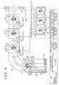
- Fig. 5 illustrates an arrangement of an air conditioning apparatus according to the fourth embodiment.
- An auxiliary fan unit 1a-1 is used as is for a blower of an outdoor unit 8.
- the auxiliary fan unit 1a-1 built into the outdoor unit 8 has a connecting mechanism on an outer frame thereof so as to be directly connected to other auxiliary fan units 1a-2, 1a-3 without having a duct 10 interposed therebetween.
- multiple auxiliary fan units may be connected together according to external static pressure requirements, so that the embodiment can be applied to, for example, a high external static pressure requirement involving a long duct.
- Fig. 5 does not show variable speed drive means (23a-1, 23a-2, 23a-3) on auxiliary fan motor drive boards (4a-1, 4a-2, 4a-3) of the auxiliary fan units (1a-1, 1a-2, 1a-3), the auxiliary fan motor drive boards (4a-1, 4a-2, 4a-3) are mounted with the variable speed drive means (23a-1, 23a-2, 23a-3) as in Fig. 4 .
- Fig. 5 also omits a control section 21 on a control board 12, the control board 12 is mounted with the control section 21.
- the auxiliary fan unit 1a-1 is used as is for the blower of the outdoor unit 8, built into the outdoor unit 8, and is then directly connected to the auxiliary fan unit 1a-2 for multiple connection of multiple auxiliary fan units (1a-1, 1a-2, 1a-3). This achieves the same effect as in the third embodiment, so that air blowing performance of the outdoor unit can be improved and reduction in capacity can be prevented.
- a signal line 13 that transmits a control signal for the fan speed from the control board 12 is short, so that the arrangement is less susceptible to external noise (disturbance). An erratic operation caused by the external noise, for example, can therefore be prevented.
Landscapes
- Engineering & Computer Science (AREA)
- Chemical & Material Sciences (AREA)
- Combustion & Propulsion (AREA)
- Mechanical Engineering (AREA)
- General Engineering & Computer Science (AREA)
- Physics & Mathematics (AREA)
- Fluid Mechanics (AREA)
- Air Conditioning Control Device (AREA)
- Other Air-Conditioning Systems (AREA)
Abstract
Description
- The present invention relates to an air conditioning apparatus.
-
JP-2003-148769-A outdoor unit 1. The exhaust from theoutdoor unit 1 is thereby further released to outside through theauxiliary fan 6. This achieves a blown air flow rate corresponding to operation of the outdoor fan 4 without having to provide special specifications for theoutdoor unit 1. An overall manufacturing cost can therefore be further reduced and a stable operating condition can be maintained without allowing exhaust short circuit or system fault to occur." (See the Abstract.) -
JP-2003-148769-A outdoor unit 1.JP-2003-148769-A - It is therefore an object of the present invention to provide an air conditioning apparatus that includes an auxiliary fan unit disposed downstream in a discharging direction of exhaust from an outdoor unit and that can satisfy required air blowing performance while achieving energy saving.
- To solve the foregoing problem, arrangements as defined in the appended claims, for example, are employed. The application includes a plurality of means for solving the foregoing problem. As an example, an aspect of the present invention provides an air conditioning apparatus, comprising: an outdoor unit containing therein an outdoor heat exchanger and an outdoor fan; and an auxiliary fan unit disposed downstream in a discharging direction of exhaust from the outdoor unit during operation of the outdoor fan, the exhaust from the outdoor unit being fed to the auxiliary fan unit. In this air conditioning apparatus, the auxiliary fan unit includes: an auxiliary fan for releasing the exhaust from the outdoor unit to an outside; and first variable speed drive means for driving the auxiliary fan at variable speeds. The outdoor unit includes: second variable speed drive means for driving the outdoor fan at variable speeds; and a control section for issuing a speed command for the outdoor fan to the second variable speed drive means. The control section issues a speed command for the auxiliary fan to the first variable speed drive means to thereby control such that the auxiliary fan and the outdoor fan increase or decrease speeds thereof at an identical speed ratio.
- The present invention can provide an air conditioning apparatus that includes an auxiliary fan unit disposed downstream in a discharging direction of exhaust from an outdoor unit and that can satisfy required air blowing performance while achieving energy saving.
- Problems, arrangements, and effects other than those described above will be apparent from the following more particular description of embodiments of the present invention.
- Other objects and advantages of the invention will become apparent from the following description of embodiments with reference to the accompanying drawings in which:
-
Fig. 1 is a diagram illustrating a structure of an air conditioning apparatus according to an embodiment of the present invention; -
Fig. 2 is a timing chart that is operatively associated with a speed of an auxiliary fan; -
Fig. 3 is an illustration showing an arrangement of an auxiliary fan unit; -
Fig. 4 is an illustration showing an arrangement of an embodiment in which a plurality of auxiliary fan units is connected together; and -
Fig. 5 is an illustration showing an arrangement of an embodiment in which an auxiliary fan unit is used as is for a blower of an outdoor unit, the auxiliary fan unit being connected to a plurality of auxiliary fan units. - Embodiments of the present invention will be described below with reference to the accompanying drawings.
- In general, an outdoor unit of an air conditioning apparatus is installed at a site at which an exhaust side of the outdoor unit is open, such as on a roof or a balcony of a building. From the standpoint of appearance of the building or a landscape, however, late outdoor units are often installed at out-of-sight places, such as inside a ceiling of a building or an underground parking lot, or at sites surrounded by a gallery. Some local authorities impose legal restrictions on the landscape. In such cases, means is often incorporated for feeding exhaust of the outdoor unit up to an outlet side of a duct that is connected to the exhaust side of the outdoor unit. Standard outdoor units, however, may not be able to achieve external static pressure that causes the exhaust of the outdoor unit to reach the duct outlet side depending on length or pressure loss of the duct, or air blowing performance of the outdoor unit concerned. In such cases, a required air flow rate cannot be achieved, which poses a problem about reduced cooling capacity and heating capacity.
- To prevent this reduction in capacity, an auxiliary fan unit that may be called a booster fan and that performs an auxiliary function is often additionally installed on the duct at the local site. The auxiliary fan unit typically includes an auxiliary fan and a fan motor. Simply structured, many auxiliary fan units have a fixed fan speed.
- For a multi-system outdoor unit in which a single outdoor unit (or a plurality of outdoor units) circulates a refrigerant through a plurality of indoor units to thereby operate the indoor units for cooling or heating, a refrigerant flow rate changes considerably according as the number of operating indoor units changes from one to two or more, or as ambient temperatures of the indoor unit and the outdoor unit change. The variations in the refrigerant flow rate are therefore addressed by performing control such that the speed of an outdoor unit fan is varied by an inverter, so that necessary refrigerating cycle capacity can be maintained to achieve a desired operation.
- The speed of the outdoor unit fan undergoes considerable variations according to, for example, the variations in the refrigerant flow rate as described above. In this case, when the auxiliary fan is operated at a constant speed at all times in time with an operation of the outdoor unit fan, and if one indoor unit for one room is operated or under light load conditions, the auxiliary fan unit produces an air flow rate higher than that of the outdoor unit. This creates suction from the auxiliary fan unit relative to the outdoor unit. Then, air is drawn and the outdoor unit is operated at an air flow rate higher than it requires, which may adversely affect a cycle condition. Possible solutions to the foregoing problem include a damper or a pressure sensor additionally installed; the damper is then used to adjust an opening angle to thereby change a passage area inside the duct, so that the air flow rate of the auxiliary fan unit can be adjusted. For example, under a condition in which the auxiliary fan unit requires a low air flow rate, the damper is closed to narrow the passage area of the duct. Resistance in the duct is thereby increased to forcedly reduce the air flow rate.
- Adjusting the damper or the pressure at the local site or building a control system therefor requires a tremendous amount of labor and increases the number of component parts, resulting in an increased cost. Operating the auxiliary fan at the constant speed consumes a considerable amount of electric power, which hampers energy saving efforts. An air conditioning apparatus according to the embodiment for solving the foregoing problems will be described below.
-
Fig. 1 is a diagram illustrating the air conditioning apparatus according to the embodiment of the present invention. Anauxiliary fan unit 1 is disposed in aduct 10 that connects anoutdoor unit 8 and aduct outlet side 9 so as to achieve external static pressure. Alouver 17 is disposed at an outlet of theduct 10. Theduct 10 has the outlet connected to awall 18. Theoutdoor unit 8 includes aheat exchanger 16, anoutdoor fan 2b, and afan motor 3b. Specifically, theoutdoor fan 2b blows air against theheat exchanger 16. Thefan motor 3b drives theoutdoor fan 2b. The air conditioning apparatus further includes other refrigerating cycle parts, such as a compressor not shown. - A flow of air through the
outdoor unit 8 and theauxiliary fan unit 1 will be described below. Energizing thefan motor 3b of theoutdoor unit 8 rotates theoutdoor fan 2b, which draws air into an inside of theoutdoor unit 8. The drawn air undergoes heat exchange as it flows past theheat exchanger 16 and is then discharged through anoutlet 11. In this case, anauxiliary fan motor 3a of theauxiliary fan unit 1 is energized to thereby rotate anauxiliary fan 2a. This causes the air discharged from theoutlet 11 to be drawn in and discharged to theduct outlet side 9 through theduct 10. - A
control section 21 that controls theoutdoor unit 8 is mounted on acontrol board 12. Thecontrol section 21 issues a control command to theoutdoor fan 2b. Variable speed drive means (inverter) 22 that drives thefan motor 3b is mounted on a fanmotor drive board 4b. A speed command signal for theoutdoor fan 2b (fan motor 3b) is transmitted from thecontrol section 21 of thecontrol board 12 to the fanmotor drive board 4b. On the fanmotor drive board 4b that receives the speed command signal, the variable speed drive means (inverter) 22 causes current to flow therefrom to thefan motor 3b based on the speed command signal received to achieve a desired variable speed. - The
auxiliary fan unit 1 will be described below. Theauxiliary fan unit 1 includes theauxiliary fan 2a and theauxiliary fan motor 3a that drives theauxiliary fan 2a. In theauxiliary fan unit 1 of this embodiment, variable speed drive means (inverter) 23 that drives theauxiliary fan motor 3a at variable speeds is mounted on an auxiliary fanmotor drive board 4a. Theauxiliary fan motor 3a and theauxiliary fan 2a are to be rotated at variable speeds by a command from the variable speed drive means (inverter) 23. Additionally, in this embodiment, speed commands for theauxiliary fan motor 3a and theauxiliary fan 2a are issued from thecontrol section 21 of theoutdoor unit 8. Specifically, thecontrol section 21 is adapted to not only transmit a speed command signal to theoutdoor fan 2b (fan motor 3b), but also issue a speed command for theauxiliary fan motor 3a and theauxiliary fan 2a. This simplifies a structure of the auxiliary fanmotor drive board 4a, thus achieving cost reduction. - It is noted that the speed command signal from the
control section 21 to theoutdoor fan 2b (fan motor 3b) is transmitted from aport 14 of thecontrol board 12 to aport 15b of the fanmotor drive board 4b via asignal line 13. Similarly, the speed command signal from thecontrol section 21 to theauxiliary fan 2a (auxiliary fan motor 3a) is transmitted from theport 14 to aport 15a of the auxiliary fanmotor drive board 4a via thesignal line 13. In this case, the auxiliary fanmotor drive board 4a and the fanmotor drive board 4b may be configured as a single board, which can achieve considerable cost reduction compared with a case at which separate boards are made. - Specific details of a method for controlling the
outdoor fan 2b and theauxiliary fan 2a will be described below. It is here noted that, in this embodiment, the control signal for the speed of theoutdoor fan 2b is transmitted to each of the auxiliary fanmotor drive board 4a and the fanmotor drive board 4b from theport 14 of thecontrol board 12 via thesignal line 13. This is, however, not the only possible method for transmitting the signal. For example, as shown inside the broken line ofFig. 1 , the control signal for the speed of theoutdoor fan 2b (speed command signal) may be transmitted to the auxiliary fanmotor drive board 4a from theport 15b of the fanmotor drive board 4b via thesignal line 13. Additionally, the auxiliary fanmotor drive board 4a and the fanmotor drive board 4b are external relative to respective fan motors. Each of the auxiliary fanmotor drive board 4a and the fanmotor drive board 4b may nonetheless be built into the corresponding fan motor. - It is here noted that, for a multi-system outdoor unit in which a single outdoor unit (or a plurality of outdoor units) circulates a refrigerant through a plurality of indoor units to thereby operate the indoor units for cooling or heating, a refrigerant flow rate changes considerably according as the number of operating indoor units changes from one to two or more, or as ambient temperatures of the indoor unit and the outdoor unit change. For example, when only one indoor unit is operated for single-room operation, the refrigerant flow rate is low and the speed of the
outdoor fan 2b of theoutdoor unit 8 is controlled to be low as compared with all-room operation. When load inside and outside the room is low, for example, when an outside temperature is low and an interior temperature is low during cooling operation, the refrigerant flow rate becomes low and the fan speed of theoutdoor unit 8 is controlled to be lower than that under heavy load. If the speed of theauxiliary fan 2a of theauxiliary fan unit 1 is fixed in such cases, a large amount of electric power is required, which hampers energy saving efforts. - If the speed of the
auxiliary fan 2a of theauxiliary fan unit 1 is fixed in such cases, and when one indoor unit for one room is operated or under light load conditions, theauxiliary fan unit 1 produces an air flow rate higher than that of the outdoor unit. This creates suction from theauxiliary fan unit 1 relative to theoutdoor unit 8. Then, air is drawn and theoutdoor unit 8 is operated at an air flow rate higher than it requires, which may at times adversely affect a refrigerating cycle condition. - The air conditioning apparatus (or may be referred to as an air conditioning system) of this embodiment thus includes the
outdoor unit 8 that contains therein theoutdoor heat exchanger 16 and theoutdoor fan 2b and theauxiliary fan unit 1 disposed downstream in a discharging direction of exhaust from theoutdoor unit 8 when theoutdoor fan 2b is operated. The exhaust from theoutdoor unit 8 is to be fed to theauxiliary fan unit 1 through theduct 10. Theauxiliary fan unit 1 includes theauxiliary fan 2a that releases the exhaust from theoutdoor unit 8 to the outside and first variable speed drive means 23 that drives theauxiliary fan 2a at variable speeds. Theoutdoor unit 8, on the other hand, includes second variable speed drive means 22 that drives theoutdoor fan 2b at variable speeds and thecontrol section 21 that gives the second variable speed drive means 22 a speed command for theoutdoor fan 2b. Thecontrol section 21 gives the first variable speed drive means 23 a speed command for theauxiliary fan 2a, thereby controlling such that the speeds of theauxiliary fan 2a and theoutdoor fan 2b increase or decrease at an identical speed ratio. - By producing such an air flow rate as to achieve the external static pressure through the foregoing arrangements, the speed can be reduced when the auxiliary fan does not require a high air flow rate. This makes small the electric power as compared with rotation at the constant speed at all times, thus achieving energy saving. The arrangements further eliminate a situation in which the auxiliary fan unit produces an air flow rate higher than that of the outdoor unit, if one indoor unit for one room is operated or under light load conditions. The refrigerating cycle condition can thus be prevented from being adversely affected as described above. In addition, the
control section 21 of theoutdoor unit 8 is adapted to issue the speed command to not only theoutdoor fan 2b, but also theauxiliary fan 2a. This eliminates the need for setting an independent control section for theauxiliary fan 2a, so that theauxiliary fan unit 1 can be configured simply. - Preferably, the
control section 21 controls such that theauxiliary fan 2a and theoutdoor fan 2b are rotated at the same speed. Further preferably, theauxiliary fan 2a and theoutdoor fan 2b each have a substantially identical diameter. This allows the same part to be used for theauxiliary fan 2a and theoutdoor fan 2b, which enables reduction in a manufacturing cost. If theauxiliary fan 2a has a diameter different from that of theoutdoor fan 2b, thecontrol section 21 controls such that, of theauxiliary fan 2a and theoutdoor fan 2b, whichever has a larger diameter rotates at a lower speed. - The
control section 21 transmits the same speed command signal to the first variable speed drive means 23 and the second variable speed drive means 22. This eliminates the need for having an independent control section for theauxiliary fan unit 1, so that both fans can be controlled so as to meet required air flow rate performance with a simple arrangement. In addition, thecontrol board 4a mounted with the first variable speed drive means 23 and thecontrol board 4b mounted with the second variable speed drive means 22 are formed from an identical board. The control boards are mounted with the receiving sections (15b, 15a) for receiving the speed command signals from thecontrol section 21. This allows the same board to be used for two different types of board, achieving reduction in the manufacturing cost. -
Fig. 2 shows graphs for illustrating the speed of theauxiliary fan 2a when theauxiliary fan 2a and theoutdoor fan 2b have the same air flow rate. - The upper graph of
Fig. 2 shows the auxiliary fan speed when a small auxiliary fan is used that delivers half (0.5 x A) of an outdoor fan air flow rate (A) at the same speed. In this case, to have the same air flow rate, the auxiliary fan speed should double (2 x B) an outdoor fan speed (B). - The middle graph of
Fig. 2 shows the auxiliary fan speed when an auxiliary fan is used that delivers the same air flow rate (A) as the outdoor fan air flow rate (A) at the same speed (specifically, the same fan is used as the outdoor fan). In this case, to cause the outdoor fan and the auxiliary fan to deliver the same air flow rate (A), the auxiliary fan is rotated at the same speed (B) as the outdoor fan that is half the speed of the upper graph ofFig. 2 . The outdoor fan speed (B) is varied in a stepwise fashion (100%, 90%, 80%, 70%, ..) as the outdoor fan air flow rate changes. - The lower graph of
Fig. 2 shows, in contrast to the upper graph ofFig. 2 , the auxiliary fan speed when a large auxiliary fan is used that delivers twice (2 x A) as high as the outdoor fan air flow rate (A) at the same speed. In this case, to cause the outdoor fan and the auxiliary fan to deliver the same air flow rate (A), the auxiliary fan speed should be half (0.5 x B)of the outdoor fan speed (B). - In order to adjust the speed of the
auxiliary fan 2a, this embodiment has a function of correcting the control signal for the fan speed of theauxiliary fan unit 1 according to an air flow rate characteristic of theauxiliary fan 2a. For example, the control signal for the fan speed of theauxiliary fan unit 1 may be subjected to multiplier conversion by changing the position of a switch on the auxiliary fanmotor drive board 4a according to the air flow rate characteristic of theauxiliary fan 2a. This allows theoutdoor unit 8 and theauxiliary fan unit 1 to be operatively associated with each other to deliver the same air flow rate even when theoutdoor fan 2b has an air flow rate characteristic different from that of theauxiliary fan 2a. - An air conditioning apparatus according to a second embodiment will be described below with reference to
Fig. 3 . -
Fig. 3 illustrates a structure of anauxiliary fan unit 1 according to this embodiment. Theauxiliary fan unit 1 includes anauxiliary fan 2a, anauxiliary fan motor 3a, and an auxiliary fanmotor drive board 4a for receiving a control signal from acontrol board 12 of anoutdoor unit 8, all built therein. Theauxiliary fan 2a, theauxiliary fan motor 3a, and the auxiliary fanmotor drive board 4a are formed from corresponding parts in theoutdoor unit 8. This permits use of common parts carried over from an air blowing system of theoutdoor unit 8. Ashroud 5 and amotor clamp 6 of theauxiliary fan unit 1 may therefore be formed from corresponding parts in theoutdoor unit 8. The common use of parts permits cost reduction and shortening of a development period. - Furthermore, the
shroud 5 and themotor clamp 6 are surrounded by an auxiliary fan unitouter frame 7. The auxiliary fan unitouter frame 7 has mechanisms disposed at upper and lower portions thereof. The mechanisms can be connected to aduct 10. The connecting mechanism, though not shown, may have a common screw fastening or other connecting mechanism. Additionally, the auxiliary fan unit of this embodiment may be incorporated in the air conditioning apparatus of other embodiments. - An air conditioning apparatus according to a third embodiment will be described below with reference to
Fig. 4 . - An
auxiliary fan unit 1 of this embodiment has the same arrangement as that described with reference to the second embodiment. Theauxiliary fan unit 1 is formed into a single module and multipleauxiliary fan units 1a-1, 1a-2, 1a-3 are connected together in the middle of aduct 10 using connecting mechanisms of anouter frame 7.Fig. 4 shows three auxiliary fan units connected together. Any number of auxiliary fan units may nonetheless be connected together, as determined depending air flow rate requirements. - All of these
auxiliary fan units 1a-1, 1a-2, 1a-3 include auxiliary fanmotor drive boards 4a-1, 4a-2, 4a-3, respectively, that are identical to that of theoutdoor unit 8. As with the control system described for the first embodiment, speed command signals for speeds ofauxiliary fans 2a-1, 2a-2, 2a-3 transmitted from acontrol section 21 of acontrol board 12 of theoutdoor unit 8 are transmitted to theauxiliary fan units 1a-1, 1a-2, 1a-3, respectively, via asignal line 13 from aport 18 of thecontrol board 12. The speed command signals are received by auxiliary fanmotor drive boards 4a-1, 4a-2, 4a-3. Variable speed drive means 23a-1, 23a-2, 23a-3 mounted on respective boards then cause variable current to flow through respectiveauxiliary fan motors 3a-1, 3a-2, 3a-3 to achieve desired speeds based on these speed command signals. - The embodiment exemplifies that the speed command signals for the speeds of the auxiliary fan motors are transmitted from the
port 14 of thecontrol board 12 via thesignal line 13 to the auxiliary fanmotor drive boards 4a-1, 4a-2, 4a-3. This is, however, not the only possible branching method of the signal line. As with the first embodiment, the control signal of the fan speed may be branched to the auxiliary fanmotor drive boards 4a-1, 4a-2, 4a-3 from aport 15b of a fanmotor drive board 4b via thesignal line 13. - Alternatively, referring to another branching method shown inside a broken line frame in
Fig. 4 , the control signal for the fan speed may be branched from aport 15a-1 of the auxiliary fanmotor drive board 4a-1 to other auxiliary fanmotor drive boards 4a-2, 4a-3 via thesignal line 13. In this case, the length of thesignal line 13 wired from the auxiliary fanmotor drive board 4a to transmit the control signal for the fan speed is short and the arrangement is less susceptible to external noise (disturbance). An erratic operation caused by the external noise can therefore be prevented. Additionally, the drive boards of fan motors (4a-1, 4a-2, 4a-3, 4b) are exemplified as being external relative to the fan motors. Nonetheless, the drive boards may be built into the fan motors. - Fan control for each of the above cases will be described below. The system includes, in addition to the
auxiliary fan unit 1a-1, the downstream auxiliary fan units (1a-2, 1a-3) disposed downstream in a discharging direction of exhaust from theauxiliary fan unit 1a-1 when anoutdoor fan 2b is operated. The exhaust from theoutdoor unit 8 is fed via aduct 10 to theauxiliary fan unit 1a-1 and further to the downstreamauxiliary fan units 1a-2, 1a-3. The downstream auxiliary fan units (1a-2, 1a-3) further include: downstream auxiliary fans (2a-2, 2a-3) for releasing the exhaust from theauxiliary fan unit 1a-1 to the outside; and third variable speed drive means (23a-2, 23a-3) that drive the downstream auxiliary fans (2a-2, 2a-3) at variable speeds. Thecontrol section 21 gives the third variable speed drive means (23a-2, 23a-3) speed commands for the downstream auxiliary fans (2a-2, 2a-3), thereby controlling such that theauxiliary fan 2a-1 and the downstream auxiliary fans (2a-2, 2a-3) increase or decrease their speeds at the same speed ratio. - By producing such an air flow rate as to achieve the external static pressure through the foregoing arrangements, the speed can be reduced when each of the auxiliary fans (2a-1, 2a-2, 2a-3) does not require a high air flow rate. This makes small the electric power as compared with rotation at the constant speed at all times, thus achieving energy saving. The arrangements further eliminate a situation in which the auxiliary fan unit (1a-1, 1a-2, 1a-3) produces an air flow rate higher than that of the outdoor unit, if one indoor unit for one room is operated or under light load conditions. The refrigerating cycle condition can thus be prevented from being adversely affected as described with reference to the first embodiment. In addition, the
control section 21 of theoutdoor unit 8 is adapted to issue the speed command to not only theoutdoor fan 2b, but also the auxiliary fans (2a-1, 2a-2, 2a-3). This eliminates the need for setting an independent control section for the auxiliary fans (2a-1, 2a-2, 2a-3), so that the auxiliary fan units (1a-1, 1a-2, 1a-3) can be configured simply. - Additionally, preferably, the
auxiliary fan 2a-1 and the downstream auxiliary fans (2a-2, 2a-3) have a substantially identical diameter and thecontrol section 21 controls such that theauxiliary fan 2a-1 and the downstream auxiliary fans (2a-2, 2a-3) rotate at the same speed. - Let (Y) Pa be the external static pressure achieved by a single unit (one module) of the
auxiliary fan unit 1a-1. Then, a two-unit (two-module) configuration of the auxiliary fan units (1a-1, 1a-2) can achieve an external static pressure of (2 x Y) Pa, a three-unit (three-module) configuration of the auxiliary fan units (1a-1, 1a-2, 1a-3) can achieve an external static pressure of (3 x Y) Pa, and an n-unit (n-module) configuration can achieve an external static pressure of (n x Y) Pa. - Assume, for example, that the external static pressure of the auxiliary fan units (1a-1, 1a-2, 1a-3) is 100 Pa when the external static pressure of a single
outdoor unit 8 is 50 Pa and pressure loss is 50 Pa. Then, the single-unit configuration of theauxiliary fan unit 1a-1 can achieve an external static pressure of up to 50 to 150 Pa, the two-unit configuration of theauxiliary fan units 1a-1, 1a-2 can achieve an external static pressure of up to 150 to 250 Pa, and the three-unit configuration of the auxiliary fan units (1a-1, 1a-2, 1a-3) can achieve an external static pressure of up to 250 to 350 Pa. This allows the number of auxiliary fan units (1) to be freely increased depending on a wide range of external static pressures, so that the embodiment can be applied to, for example, a long duct having a high static pressure. - A fourth embodiment of the present invention will be described below with reference to
Fig. 5 . -
Fig. 5 illustrates an arrangement of an air conditioning apparatus according to the fourth embodiment. Anauxiliary fan unit 1a-1 is used as is for a blower of anoutdoor unit 8. In this case, theauxiliary fan unit 1a-1 built into theoutdoor unit 8 has a connecting mechanism on an outer frame thereof so as to be directly connected to otherauxiliary fan units 1a-2, 1a-3 without having aduct 10 interposed therebetween. As with the third embodiment, multiple auxiliary fan units may be connected together according to external static pressure requirements, so that the embodiment can be applied to, for example, a high external static pressure requirement involving a long duct. Other like or corresponding parts are identified by the same reference numerals as those used for the third embodiment and the control method is the same as that in the third embodiment, so that descriptions for those will not be hereunder duplicated. It is noted that, althoughFig. 5 does not show variable speed drive means (23a-1, 23a-2, 23a-3) on auxiliary fan motor drive boards (4a-1, 4a-2, 4a-3) of the auxiliary fan units (1a-1, 1a-2, 1a-3), the auxiliary fan motor drive boards (4a-1, 4a-2, 4a-3) are mounted with the variable speed drive means (23a-1, 23a-2, 23a-3) as inFig. 4 . AlthoughFig. 5 also omits acontrol section 21 on acontrol board 12, thecontrol board 12 is mounted with thecontrol section 21. - If capacity of the
outdoor unit 8 may be reduced due to, for example, high temperature ambient conditions, and construction conditions including increased connection capacity of indoor units and long piping, theauxiliary fan unit 1a-1 is used as is for the blower of theoutdoor unit 8, built into theoutdoor unit 8, and is then directly connected to theauxiliary fan unit 1a-2 for multiple connection of multiple auxiliary fan units (1a-1, 1a-2, 1a-3). This achieves the same effect as in the third embodiment, so that air blowing performance of the outdoor unit can be improved and reduction in capacity can be prevented. - A
signal line 13 that transmits a control signal for the fan speed from thecontrol board 12 is short, so that the arrangement is less susceptible to external noise (disturbance). An erratic operation caused by the external noise, for example, can therefore be prevented. - The above embodiments of the invention as well as the appended claims and figures show multiple characterizing features of the invention in specific combinations. The skilled person will easily be able to consider further combinations or sub-combinations of these features in order to adapt the invention as defined in the claims to his specific needs.
Claims (10)
- An air conditioning apparatus, comprising:an outdoor unit (8) containing therein an outdoor heat exchanger (16) and an outdoor fan (2b); andan auxiliary fan unit (1) disposed downstream in a discharging direction of exhaust from the outdoor unit (8) during operation of the outdoor fan (2b), the exhaust from the outdoor unit (8) being fed to the auxiliary fan unit (1), whereinthe auxiliary fan unit (1) includes:an auxiliary fan (2a) for releasing the exhaust from the outdoor unit (8) to an outside; andfirst variable speed drive means (23) for driving the auxiliary fan (2a) at variable speeds;the outdoor unit (8) includes:second variable speed drive means (22) for driving the outdoor fan (2b) at variable speeds; anda control section for issuing a speed command for the outdoor fan (2b) to the second variable speed drive means (22), the control section issuing a speed command for the auxiliary fan (2a) to the first variable speed drive means (23) to thereby control such that the auxiliary fan (2a) and the outdoor fan (2b) increase or decrease speeds thereof at an identical speed ratio.
- The air conditioning apparatus according to claim 1, wherein
the exhaust from the outdoor unit (8) is fed to the auxiliary fan (2a) by way of a duct member. - The air conditioning apparatus according to claim 1, wherein
the control section controls such that the auxiliary fan (2a) and the outdoor fan (2b) rotate at an identical speed. - The air conditioning apparatus according to claim 2, wherein
the auxiliary fan (2a) and the outdoor fan (2b) have a substantially identical diameter. - The air conditioning apparatus according to claim 1, wherein
the auxiliary fan (2a) and the outdoor fan (2b) have different diameters from each other; and
the control section controls such that, of the auxiliary fan (2a) and the outdoor fan (2b), whichever has a larger diameter rotates at a lower speed. - The air conditioning apparatus according to claim 1, wherein
the control section transmits an identical speed command signal to the first variable speed drive means (23) and the second variable speed drive means (22). - The air conditioning apparatus according to claim 1, wherein
a control board (12) mounted with the first variable speed drive means (23) and a control board (12) mounted with the second variable speed drive means (22) are formed from a single, identical board; and
these control boards (12) are mounted with the receiving sections for receiving the speed command signals from the control section. - The air conditioning apparatus according to claim 1, further comprising:in addition to the auxiliary fan unit (1), a downstream auxiliary fan unit (1) disposed downstream in a discharging direction of exhaust from the auxiliary fan unit (1) during operation of the outdoor fan (2b), whereinthe exhaust from the outdoor unit (8) is to be fed to the auxiliary fan unit (1) and further to the downstream auxiliary fan unit (1);the downstream auxiliary fan unit (1) includes:a downstream auxiliary fan (2a-2, 2a-3) for releasing the exhaust from the auxiliary fan unit (1) to the outside; andthird variable speed drive means for driving the downstream auxiliary fan (2a-2, 2a-3) at variable speeds; andthe control section issues a speed command for the downstream auxiliary fan (2a-2, 2a-3) to the third variable speed drive means to thereby control such that the auxiliary fan (2a) and the downstream auxiliary fan (2a-2, 2a-3) increase or decrease speeds thereof at an identical speed ratio.
- The air conditioning apparatus according to claim 8, wherein
the auxiliary fan (2a) and the downstream auxiliary fan (2a-2, 2a-3) have a substantially identical diameter; and
the control section controls such that the auxiliary fan (2a) and the downstream auxiliary fan (2a-2, 2a-3) rotate at an identical speed. - The air conditioning apparatus according to claim 8, wherein
the exhaust from the outdoor unit (8) is fed to the auxiliary fan unit (1) and further to the downstream auxiliary fan unit (1) by way of a duct member.
Applications Claiming Priority (1)
| Application Number | Priority Date | Filing Date | Title |
|---|---|---|---|
| JP2011186728A JP5520900B2 (en) | 2011-08-30 | 2011-08-30 | Air conditioner |
Publications (3)
| Publication Number | Publication Date |
|---|---|
| EP2573476A2 true EP2573476A2 (en) | 2013-03-27 |
| EP2573476A3 EP2573476A3 (en) | 2014-05-14 |
| EP2573476B1 EP2573476B1 (en) | 2019-04-24 |
Family
ID=46750202
Family Applications (1)
| Application Number | Title | Priority Date | Filing Date |
|---|---|---|---|
| EP12179997.7A Active EP2573476B1 (en) | 2011-08-30 | 2012-08-10 | Air conditioning apparatus |
Country Status (3)
| Country | Link |
|---|---|
| EP (1) | EP2573476B1 (en) |
| JP (1) | JP5520900B2 (en) |
| ES (1) | ES2738202T3 (en) |
Cited By (3)
| Publication number | Priority date | Publication date | Assignee | Title |
|---|---|---|---|---|
| CN104697124A (en) * | 2013-12-09 | 2015-06-10 | 广东美的制冷设备有限公司 | Natural wind air conditioner as well as control device and control method thereof |
| CN108278661A (en) * | 2018-01-11 | 2018-07-13 | 广东美的制冷设备有限公司 | The control method and air conditioner of air conditioner |
| FR3088992A1 (en) * | 2018-11-28 | 2020-05-29 | Thomas Etchenique | Device and method for ventilating a compression and condensation unit of an air conditioning system |
Families Citing this family (3)
| Publication number | Priority date | Publication date | Assignee | Title |
|---|---|---|---|---|
| CN105805852A (en) * | 2016-03-28 | 2016-07-27 | 朱虹斐 | Energy saving air conditioning outer unit |
| JP6784161B2 (en) * | 2016-12-12 | 2020-11-11 | ダイキン工業株式会社 | Air conditioning system |
| JP7153263B2 (en) * | 2018-07-30 | 2022-10-14 | クリフ株式会社 | pressure regulating damper |
Citations (1)
| Publication number | Priority date | Publication date | Assignee | Title |
|---|---|---|---|---|
| JP2003148769A (en) | 2001-11-13 | 2003-05-21 | Daikin Ind Ltd | Outdoor equipment of air conditioner |
Family Cites Families (8)
| Publication number | Priority date | Publication date | Assignee | Title |
|---|---|---|---|---|
| JPS51132644A (en) * | 1975-05-14 | 1976-11-17 | Matsushita Seiko Co Ltd | Ventilator for aggregate housing or the like |
| JPS6113238U (en) * | 1984-06-29 | 1986-01-25 | 株式会社東芝 | air conditioner |
| JPH06257841A (en) * | 1993-03-04 | 1994-09-16 | Ebara Corp | Method for operating booster fan of air conditioner |
| JP3985324B2 (en) * | 1998-02-10 | 2007-10-03 | 株式会社大林組 | Room ventilation method during building finishing work |
| US7097111B2 (en) * | 2000-07-21 | 2006-08-29 | Gun Valley Temperature Controls Llc | Environmental control system and method for storage buildings |
| JP3601596B2 (en) * | 2001-03-19 | 2004-12-15 | 株式会社日立製作所 | Air conditioner |
| JP4038352B2 (en) * | 2001-08-24 | 2008-01-23 | 株式会社日立産機システム | Clean room |
| JP3812514B2 (en) * | 2002-08-21 | 2006-08-23 | 三菱電機株式会社 | Waste heat blower |
-
2011
- 2011-08-30 JP JP2011186728A patent/JP5520900B2/en active Active
-
2012
- 2012-08-10 ES ES12179997T patent/ES2738202T3/en active Active
- 2012-08-10 EP EP12179997.7A patent/EP2573476B1/en active Active
Patent Citations (1)
| Publication number | Priority date | Publication date | Assignee | Title |
|---|---|---|---|---|
| JP2003148769A (en) | 2001-11-13 | 2003-05-21 | Daikin Ind Ltd | Outdoor equipment of air conditioner |
Cited By (4)
| Publication number | Priority date | Publication date | Assignee | Title |
|---|---|---|---|---|
| CN104697124A (en) * | 2013-12-09 | 2015-06-10 | 广东美的制冷设备有限公司 | Natural wind air conditioner as well as control device and control method thereof |
| CN104697124B (en) * | 2013-12-09 | 2017-11-10 | 广东美的制冷设备有限公司 | Air conditioner supplying natural wind and its control device and control method |
| CN108278661A (en) * | 2018-01-11 | 2018-07-13 | 广东美的制冷设备有限公司 | The control method and air conditioner of air conditioner |
| FR3088992A1 (en) * | 2018-11-28 | 2020-05-29 | Thomas Etchenique | Device and method for ventilating a compression and condensation unit of an air conditioning system |
Also Published As
| Publication number | Publication date |
|---|---|
| JP5520900B2 (en) | 2014-06-11 |
| EP2573476B1 (en) | 2019-04-24 |
| ES2738202T3 (en) | 2020-01-20 |
| JP2013050222A (en) | 2013-03-14 |
| EP2573476A3 (en) | 2014-05-14 |
Similar Documents
| Publication | Publication Date | Title |
|---|---|---|
| EP2573476B1 (en) | Air conditioning apparatus | |
| US5413278A (en) | Remotely activated opposing pressure air flow control register | |
| US5718628A (en) | Air conditioning method in machine room having forced air-cooling equipment housed therein | |
| CN102607140B (en) | Air-conditioner | |
| CN104764159B (en) | Method for positioning indoor unit of multi-split air conditioner and multi-split air conditioner | |
| JPH0462352A (en) | Control of duct air conditioner | |
| US20230250973A1 (en) | Packaged terminal air conditioner (ptac) with an integrated energy recovery ventilator (erv) or heat recovery ventilator (hrv) | |
| WO2015079548A1 (en) | Air conditioning system | |
| US20220146124A1 (en) | Air conditioning system | |
| JP4979308B2 (en) | Air conditioning system | |
| JP2013061125A (en) | Air conditioner | |
| US12320540B2 (en) | Air conditioning system | |
| KR20170090837A (en) | Air-conditioner and the controlling method for the same | |
| JP2018096593A (en) | Air conditioning system | |
| KR102591703B1 (en) | air conditioning system | |
| CN103423843B (en) | The method of wind pipe type indoor set and control wind pipe type indoor set capacity | |
| JPS6335321Y2 (en) | ||
| US20170314820A1 (en) | Packaged hvac unit with secondary system capability | |
| WO2023139725A1 (en) | Heat exchange ventilation system | |
| JPH05106865A (en) | Air conditioning system with ventilation function | |
| JPH0875231A (en) | Variable air conditioning system | |
| JPH05312377A (en) | Controller for air conditioner | |
| WO2016117097A1 (en) | Air-conditioning system | |
| JP2006284096A (en) | Negative pressure and air conditioning stabilization system in the room such as kitchen | |
| JPH0486908A (en) | Cooling system |
Legal Events
| Date | Code | Title | Description |
|---|---|---|---|
| PUAI | Public reference made under article 153(3) epc to a published international application that has entered the european phase |
Free format text: ORIGINAL CODE: 0009012 |
|
| 17P | Request for examination filed |
Effective date: 20121120 |
|
| AK | Designated contracting states |
Kind code of ref document: A2 Designated state(s): AL AT BE BG CH CY CZ DE DK EE ES FI FR GB GR HR HU IE IS IT LI LT LU LV MC MK MT NL NO PL PT RO RS SE SI SK SM TR |
|
| AX | Request for extension of the european patent |
Extension state: BA ME |
|
| PUAL | Search report despatched |
Free format text: ORIGINAL CODE: 0009013 |
|
| AK | Designated contracting states |
Kind code of ref document: A3 Designated state(s): AL AT BE BG CH CY CZ DE DK EE ES FI FR GB GR HR HU IE IS IT LI LT LU LV MC MK MT NL NO PL PT RO RS SE SI SK SM TR |
|
| AX | Request for extension of the european patent |
Extension state: BA ME |
|
| RIC1 | Information provided on ipc code assigned before grant |
Ipc: F24F 11/00 20060101AFI20140409BHEP Ipc: F24F 1/06 20110101ALI20140409BHEP |
|
| RAP1 | Party data changed (applicant data changed or rights of an application transferred) |
Owner name: HITACHI APPLIANCES, INC. |
|
| RAP1 | Party data changed (applicant data changed or rights of an application transferred) |
Owner name: JOHNSON CONTROLS-HITACHI AIR CONDITIONING TECHNOLO |
|
| RAP1 | Party data changed (applicant data changed or rights of an application transferred) |
Owner name: HITACHI-JOHNSON CONTROLS AIR CONDITIONING, INC. |
|
| STAA | Information on the status of an ep patent application or granted ep patent |
Free format text: STATUS: EXAMINATION IS IN PROGRESS |
|
| 17Q | First examination report despatched |
Effective date: 20180504 |
|
| GRAP | Despatch of communication of intention to grant a patent |
Free format text: ORIGINAL CODE: EPIDOSNIGR1 |
|
| STAA | Information on the status of an ep patent application or granted ep patent |
Free format text: STATUS: GRANT OF PATENT IS INTENDED |
|
| INTG | Intention to grant announced |
Effective date: 20181107 |
|
| GRAS | Grant fee paid |
Free format text: ORIGINAL CODE: EPIDOSNIGR3 |
|
| GRAA | (expected) grant |
Free format text: ORIGINAL CODE: 0009210 |
|
| STAA | Information on the status of an ep patent application or granted ep patent |
Free format text: STATUS: THE PATENT HAS BEEN GRANTED |
|
| AK | Designated contracting states |
Kind code of ref document: B1 Designated state(s): AL AT BE BG CH CY CZ DE DK EE ES FI FR GB GR HR HU IE IS IT LI LT LU LV MC MK MT NL NO PL PT RO RS SE SI SK SM TR |
|
| REG | Reference to a national code |
Ref country code: GB Ref legal event code: FG4D |
|
| REG | Reference to a national code |
Ref country code: CH Ref legal event code: EP |
|
| REG | Reference to a national code |
Ref country code: AT Ref legal event code: REF Ref document number: 1124609 Country of ref document: AT Kind code of ref document: T Effective date: 20190515 Ref country code: IE Ref legal event code: FG4D |
|
| REG | Reference to a national code |
Ref country code: DE Ref legal event code: R096 Ref document number: 602012059273 Country of ref document: DE |
|
| REG | Reference to a national code |
Ref country code: NL Ref legal event code: MP Effective date: 20190424 |
|
| REG | Reference to a national code |
Ref country code: LT Ref legal event code: MG4D |
|
| PG25 | Lapsed in a contracting state [announced via postgrant information from national office to epo] |
Ref country code: NL Free format text: LAPSE BECAUSE OF FAILURE TO SUBMIT A TRANSLATION OF THE DESCRIPTION OR TO PAY THE FEE WITHIN THE PRESCRIBED TIME-LIMIT Effective date: 20190424 |
|
| PG25 | Lapsed in a contracting state [announced via postgrant information from national office to epo] |
Ref country code: NO Free format text: LAPSE BECAUSE OF FAILURE TO SUBMIT A TRANSLATION OF THE DESCRIPTION OR TO PAY THE FEE WITHIN THE PRESCRIBED TIME-LIMIT Effective date: 20190724 Ref country code: FI Free format text: LAPSE BECAUSE OF FAILURE TO SUBMIT A TRANSLATION OF THE DESCRIPTION OR TO PAY THE FEE WITHIN THE PRESCRIBED TIME-LIMIT Effective date: 20190424 Ref country code: LT Free format text: LAPSE BECAUSE OF FAILURE TO SUBMIT A TRANSLATION OF THE DESCRIPTION OR TO PAY THE FEE WITHIN THE PRESCRIBED TIME-LIMIT Effective date: 20190424 Ref country code: SE Free format text: LAPSE BECAUSE OF FAILURE TO SUBMIT A TRANSLATION OF THE DESCRIPTION OR TO PAY THE FEE WITHIN THE PRESCRIBED TIME-LIMIT Effective date: 20190424 Ref country code: HR Free format text: LAPSE BECAUSE OF FAILURE TO SUBMIT A TRANSLATION OF THE DESCRIPTION OR TO PAY THE FEE WITHIN THE PRESCRIBED TIME-LIMIT Effective date: 20190424 Ref country code: AL Free format text: LAPSE BECAUSE OF FAILURE TO SUBMIT A TRANSLATION OF THE DESCRIPTION OR TO PAY THE FEE WITHIN THE PRESCRIBED TIME-LIMIT Effective date: 20190424 Ref country code: PT Free format text: LAPSE BECAUSE OF FAILURE TO SUBMIT A TRANSLATION OF THE DESCRIPTION OR TO PAY THE FEE WITHIN THE PRESCRIBED TIME-LIMIT Effective date: 20190824 |
|
| PG25 | Lapsed in a contracting state [announced via postgrant information from national office to epo] |
Ref country code: GR Free format text: LAPSE BECAUSE OF FAILURE TO SUBMIT A TRANSLATION OF THE DESCRIPTION OR TO PAY THE FEE WITHIN THE PRESCRIBED TIME-LIMIT Effective date: 20190725 Ref country code: BG Free format text: LAPSE BECAUSE OF FAILURE TO SUBMIT A TRANSLATION OF THE DESCRIPTION OR TO PAY THE FEE WITHIN THE PRESCRIBED TIME-LIMIT Effective date: 20190724 Ref country code: LV Free format text: LAPSE BECAUSE OF FAILURE TO SUBMIT A TRANSLATION OF THE DESCRIPTION OR TO PAY THE FEE WITHIN THE PRESCRIBED TIME-LIMIT Effective date: 20190424 Ref country code: RS Free format text: LAPSE BECAUSE OF FAILURE TO SUBMIT A TRANSLATION OF THE DESCRIPTION OR TO PAY THE FEE WITHIN THE PRESCRIBED TIME-LIMIT Effective date: 20190424 Ref country code: PL Free format text: LAPSE BECAUSE OF FAILURE TO SUBMIT A TRANSLATION OF THE DESCRIPTION OR TO PAY THE FEE WITHIN THE PRESCRIBED TIME-LIMIT Effective date: 20190424 |
|
| REG | Reference to a national code |
Ref country code: AT Ref legal event code: MK05 Ref document number: 1124609 Country of ref document: AT Kind code of ref document: T Effective date: 20190424 |
|
| PG25 | Lapsed in a contracting state [announced via postgrant information from national office to epo] |
Ref country code: IS Free format text: LAPSE BECAUSE OF FAILURE TO SUBMIT A TRANSLATION OF THE DESCRIPTION OR TO PAY THE FEE WITHIN THE PRESCRIBED TIME-LIMIT Effective date: 20190824 |
|
| REG | Reference to a national code |
Ref country code: ES Ref legal event code: FG2A Ref document number: 2738202 Country of ref document: ES Kind code of ref document: T3 Effective date: 20200120 |
|
| REG | Reference to a national code |
Ref country code: DE Ref legal event code: R097 Ref document number: 602012059273 Country of ref document: DE |
|
| PG25 | Lapsed in a contracting state [announced via postgrant information from national office to epo] |
Ref country code: EE Free format text: LAPSE BECAUSE OF FAILURE TO SUBMIT A TRANSLATION OF THE DESCRIPTION OR TO PAY THE FEE WITHIN THE PRESCRIBED TIME-LIMIT Effective date: 20190424 Ref country code: DK Free format text: LAPSE BECAUSE OF FAILURE TO SUBMIT A TRANSLATION OF THE DESCRIPTION OR TO PAY THE FEE WITHIN THE PRESCRIBED TIME-LIMIT Effective date: 20190424 Ref country code: SK Free format text: LAPSE BECAUSE OF FAILURE TO SUBMIT A TRANSLATION OF THE DESCRIPTION OR TO PAY THE FEE WITHIN THE PRESCRIBED TIME-LIMIT Effective date: 20190424 Ref country code: CZ Free format text: LAPSE BECAUSE OF FAILURE TO SUBMIT A TRANSLATION OF THE DESCRIPTION OR TO PAY THE FEE WITHIN THE PRESCRIBED TIME-LIMIT Effective date: 20190424 Ref country code: AT Free format text: LAPSE BECAUSE OF FAILURE TO SUBMIT A TRANSLATION OF THE DESCRIPTION OR TO PAY THE FEE WITHIN THE PRESCRIBED TIME-LIMIT Effective date: 20190424 Ref country code: RO Free format text: LAPSE BECAUSE OF FAILURE TO SUBMIT A TRANSLATION OF THE DESCRIPTION OR TO PAY THE FEE WITHIN THE PRESCRIBED TIME-LIMIT Effective date: 20190424 |
|
| PG25 | Lapsed in a contracting state [announced via postgrant information from national office to epo] |
Ref country code: SM Free format text: LAPSE BECAUSE OF FAILURE TO SUBMIT A TRANSLATION OF THE DESCRIPTION OR TO PAY THE FEE WITHIN THE PRESCRIBED TIME-LIMIT Effective date: 20190424 Ref country code: IT Free format text: LAPSE BECAUSE OF FAILURE TO SUBMIT A TRANSLATION OF THE DESCRIPTION OR TO PAY THE FEE WITHIN THE PRESCRIBED TIME-LIMIT Effective date: 20190424 |
|
| PLBE | No opposition filed within time limit |
Free format text: ORIGINAL CODE: 0009261 |
|
| STAA | Information on the status of an ep patent application or granted ep patent |
Free format text: STATUS: NO OPPOSITION FILED WITHIN TIME LIMIT |
|
| REG | Reference to a national code |
Ref country code: DE Ref legal event code: R119 Ref document number: 602012059273 Country of ref document: DE |
|
| PG25 | Lapsed in a contracting state [announced via postgrant information from national office to epo] |
Ref country code: TR Free format text: LAPSE BECAUSE OF FAILURE TO SUBMIT A TRANSLATION OF THE DESCRIPTION OR TO PAY THE FEE WITHIN THE PRESCRIBED TIME-LIMIT Effective date: 20190424 |
|
| 26N | No opposition filed |
Effective date: 20200127 |
|
| GBPC | Gb: european patent ceased through non-payment of renewal fee |
Effective date: 20190810 |
|
| PG25 | Lapsed in a contracting state [announced via postgrant information from national office to epo] |
Ref country code: MC Free format text: LAPSE BECAUSE OF FAILURE TO SUBMIT A TRANSLATION OF THE DESCRIPTION OR TO PAY THE FEE WITHIN THE PRESCRIBED TIME-LIMIT Effective date: 20190424 Ref country code: LI Free format text: LAPSE BECAUSE OF NON-PAYMENT OF DUE FEES Effective date: 20190831 Ref country code: SI Free format text: LAPSE BECAUSE OF FAILURE TO SUBMIT A TRANSLATION OF THE DESCRIPTION OR TO PAY THE FEE WITHIN THE PRESCRIBED TIME-LIMIT Effective date: 20190424 Ref country code: CH Free format text: LAPSE BECAUSE OF NON-PAYMENT OF DUE FEES Effective date: 20190831 Ref country code: LU Free format text: LAPSE BECAUSE OF NON-PAYMENT OF DUE FEES Effective date: 20190810 |
|
| REG | Reference to a national code |
Ref country code: BE Ref legal event code: MM Effective date: 20190831 |
|
| PG25 | Lapsed in a contracting state [announced via postgrant information from national office to epo] |
Ref country code: IE Free format text: LAPSE BECAUSE OF NON-PAYMENT OF DUE FEES Effective date: 20190810 Ref country code: DE Free format text: LAPSE BECAUSE OF NON-PAYMENT OF DUE FEES Effective date: 20200303 |
|
| PG25 | Lapsed in a contracting state [announced via postgrant information from national office to epo] |
Ref country code: GB Free format text: LAPSE BECAUSE OF NON-PAYMENT OF DUE FEES Effective date: 20190810 Ref country code: BE Free format text: LAPSE BECAUSE OF NON-PAYMENT OF DUE FEES Effective date: 20190831 |
|
| PG25 | Lapsed in a contracting state [announced via postgrant information from national office to epo] |
Ref country code: CY Free format text: LAPSE BECAUSE OF FAILURE TO SUBMIT A TRANSLATION OF THE DESCRIPTION OR TO PAY THE FEE WITHIN THE PRESCRIBED TIME-LIMIT Effective date: 20190424 |
|
| PG25 | Lapsed in a contracting state [announced via postgrant information from national office to epo] |
Ref country code: MT Free format text: LAPSE BECAUSE OF FAILURE TO SUBMIT A TRANSLATION OF THE DESCRIPTION OR TO PAY THE FEE WITHIN THE PRESCRIBED TIME-LIMIT Effective date: 20190424 Ref country code: HU Free format text: LAPSE BECAUSE OF FAILURE TO SUBMIT A TRANSLATION OF THE DESCRIPTION OR TO PAY THE FEE WITHIN THE PRESCRIBED TIME-LIMIT; INVALID AB INITIO Effective date: 20120810 |
|
| PG25 | Lapsed in a contracting state [announced via postgrant information from national office to epo] |
Ref country code: MK Free format text: LAPSE BECAUSE OF FAILURE TO SUBMIT A TRANSLATION OF THE DESCRIPTION OR TO PAY THE FEE WITHIN THE PRESCRIBED TIME-LIMIT Effective date: 20190424 |
|
| PGFP | Annual fee paid to national office [announced via postgrant information from national office to epo] |
Ref country code: ES Payment date: 20250901 Year of fee payment: 14 |
|
| PGFP | Annual fee paid to national office [announced via postgrant information from national office to epo] |
Ref country code: FR Payment date: 20250723 Year of fee payment: 14 |