EP2573432A1 - Sealing structure - Google Patents
Sealing structure Download PDFInfo
- Publication number
- EP2573432A1 EP2573432A1 EP12185151A EP12185151A EP2573432A1 EP 2573432 A1 EP2573432 A1 EP 2573432A1 EP 12185151 A EP12185151 A EP 12185151A EP 12185151 A EP12185151 A EP 12185151A EP 2573432 A1 EP2573432 A1 EP 2573432A1
- Authority
- EP
- European Patent Office
- Prior art keywords
- ring
- diameter
- insertion member
- larger
- smaller
- Prior art date
- Legal status (The legal status is an assumption and is not a legal conclusion. Google has not performed a legal analysis and makes no representation as to the accuracy of the status listed.)
- Granted
Links
Images



Classifications
-
- F—MECHANICAL ENGINEERING; LIGHTING; HEATING; WEAPONS; BLASTING
- F16—ENGINEERING ELEMENTS AND UNITS; GENERAL MEASURES FOR PRODUCING AND MAINTAINING EFFECTIVE FUNCTIONING OF MACHINES OR INSTALLATIONS; THERMAL INSULATION IN GENERAL
- F16J—PISTONS; CYLINDERS; SEALINGS
- F16J15/00—Sealings
- F16J15/16—Sealings between relatively-moving surfaces
- F16J15/166—Sealings between relatively-moving surfaces with means to prevent the extrusion of the packing
Definitions
- the present invention relates to a sealing structure using an O-ring for preventing fluid leakage.
- the hydrogen tank has a cylindrical outer shape and has an end provided with a cylindrical connector portion (reception member) for a valve body (insertion member) to be inserted in.
- the connector portion has an inner circumferential surface with an inner threaded portion formed therein.
- the valve body has an outer circumferential surface with an outer threaded portion formed thereon.
- Japanese Patent No. 3543617 discloses a sealing device including a shaft (insertion member), a shaft hole (reception member), a sealing ring (O-ring), a back-up ring.
- An annular attachment groove is formed in either one of the shaft and the shaft hole with the sealing ring and the back-up ring fitted in the attachment groove.
- Japanese Unexamined Patent Application Publication No. 2002-161983 discloses a sealing device including a shaft (insertion member) and a housing (reception member) coaxially fitted with each other, two back-up rings, and a sealing ring (O-ring) sandwiched between the two back-up rings.
- the sealing ring and the back-up rings are fitted inside an annular attachment groove formed in either one of the shaft and the housing.
- Each back-up ring has a taper formed to come in total contact with and abut on each of tapers formed at both end portions of the attachment groove.
- a shaft (insertion member) 8 has an annular attachment groove 13.
- An O-ring 10 and two back-up rings 11, 12 are fitted into the annular attachment groove 13 and then the shaft 8 is inserted into a housing (reception member) 9.
- the outer diameter of the shaft 8 is made slightly smaller than the inner diameter of the housing 9 in cross section in consideration of ease of fitting of the shaft 8 into the housing 9 and manufacturing errors.
- the present invention provides a sealing structure comprising:
- the first smaller-diameter columnar portion of the insertion member first enters the space defined by the inner circumferential surface of the second larger-diameter cylindrical portion of the reception member.
- the inner diameter of the second larger-diameter cylindrical portion of the reception member (an inner diameter L31 to be described later) is larger than the outer diameter of the first smaller-diameter columnar portion of the insertion member (an outer diameter L22 to be described later). Accordingly, the insertion member can be inserted easily into the reception member without the first smaller-diameter columnar portion of the insertion member contacting the inner surface of the second larger-diameter cylindrical portion of the reception member. That is, the outer circumferential surface of the first smaller-diameter columnar portion and the inner circumferential surface of the second larger-diameter cylindrical portion of the reception member are less likely to sustain damage.
- the O-ring When the insertion member is inserted further into the reception member from the above state, the O-ring is elastically deformed by being pressed into the gap between the outer circumferential surface of the first smaller-diameter columnar portion of the insertion member and the inner circumferential surface of the second larger-diameter cylindrical portion of the reception member. At this time, the magnitudes of the forces by which the outer circumferential surface of the first smaller-diameter columnar portion of the insertion member presses the O-ring in the outward radial directions of the O-ring are uniform throughout the O-ring's annular contact surface with the first smaller-diameter columnar portion.
- the magnitudes of the forces by which the inner circumferential surface of the second larger-diameter cylindrical portion of the reception member presses the O-ring in inward radial directions of the O-ring are uniform throughout the O-ring's annular contact surface with the second larger-diameter cylindrical portion.
- the O-ring serves as a guide when the insertion member is inserted into the reception member. Accordingly, it is possible to easily fit the insertion member 2 into the reception member 3 and prevent damage to the outer circumferential surface of the insertion member and to the inner circumferential surface of the reception member.
- the accommodation region for accommodating the O-ring is defined by the outer circumferential surface of the first smaller-diameter columnar portion, the outer surfaces of the first step portion, the inner circumferential surface of the second larger-diameter cylindrical portion, and the inner surfaces of the second step portion, and the O-ring is fitted inside the accommodation region.
- the O-ring properly presses the outer circumferential surface of the insertion member inwardly in the radial direction while properly pressing the inner circumferential surface of the reception member outwardly in the radial direction, resulting in sealing of the clearance between the insertion member and the reception member. Consequently, it is possible to prevent fluid leakage caused by variations in the pressure from the tank.
- the sealing structure is configured so that it further comprises:
- the first back-up ring's surface opposed to the outer surfaces of the first step portion is formed to come in total contact with the outer surfaces of the first step portion. Accordingly, the first back-up ring makes close contact with the first step portion when the pressure inside the accommodation region becomes higher on the reception member side.
- the second back-up ring's surface opposed to the inner surfaces of the second step portion is formed to come in total contact with the inner surfaces of the second step portion. Accordingly, the second back-up ring makes close contact with the second step portion when the pressure inside the accommodation region becomes higher on the insertion member side.
- the sealing structure is configured so that:
- the first back-up ring when the pressure inside the accommodation region becomes higher on the reception member side, the first back-up ring is deformed along the first taper face, presses the first taper inwardly in the radial direction and presses the inner circumferential surface of the second larger-diameter cylindrical portion outwardly in the radial direction. Accordingly, the first back-up ring seals the clearance between the first back-up ring and the outer circumferential surface of the insertion member and the clearance between the first back-up ring and the inner circumferential surface of the reception member. Consequently, the O-ring can be prevented from being caught in the clearance and damaged to ensure more proper sealing against fluid leakage.
- the sealing structure is configured so that:
- the first back-up ring is moved toward the insertion member side by a predetermined distance according to the magnitude of the pressure.
- the movement of the first back-up ring is restricted by the shape of the first taper face (tapering down in a direction of insertion of the insertion member further into the reception member).
- the first back-up ring makes close contact with each of the first taper face and the inner circumferential surface of the second larger-diameter cylindrical portion to ensure improved sealing performances. The same holds true for the second back-up ring.
- the sealing structure is configured so that:
- the present invention provides a sealing structure that permits easy fitting of the insertion member into the reception member and that prevents damage to the insertion member and the reception member.
- FIGs. 1-6D an embodiment of the present invention will be described in detail with reference to FIGs. 1-6D .
- Like components are denoted by like reference numerals and detailed descriptions will be omitted.
- FIGs. 1-3 for the sake of convenience, an O-ring 4 and first and second back-up rings 5, 6 are drawn to a larger scale than an insertion member 2 and a reception member 3.
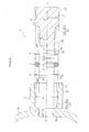
- FIG. 1 is an exploded schematic view of a sealing structure according an embodiment of the present invention.
- FIG. 2 is a cross sectional view of the sealing structure taken along a plane including a central axis of the sealing structure.
- a sealing structure 1 includes the insertion member 2, the reception member 3, the O-ring 4, the first back-up ring 5, and the second back-up ring 6.
- the sealing structure 1 includes the connector portion (reception member 3) of, for example, a hydrogen tank (tank body 3a: see FIG. 1 ) and the valve body (insertion member 2) screw-engaged with the connector portion.
- the sealing structure 1 is for sealing a clearance formed when the connector portion is fitted into the valve body.
- the hydrogen tank supplies hydrogen to a fuel cell (not shown) where the hydrogen is reacted with oxygen between electrodes to generate electric power.
- the application of the sealing structure 1, however, is not limited the above example.
- central axis X refers to a central axis that the insertion member 2 and the reception member 3 have in common when these members are coaxially fitted with each other.
- the insertion member 2 includes a larger-diameter columnar portion 21, a smaller-diameter columnar portion 22, and a step portion 23.
- the larger-diameter columnar portion 21 (first larger-diameter columnar portion) has a columnar outer shape, and has an outer diameter L21 (see FIG. 2 ).
- the larger-diameter columnar portion 21 has, on an end thereof (one end opposite to the other that faces the reception member 3 when the insertion member 2 is fitted into the reception member 3), an outer threaded portion 24 for engaging the insertion member 2 with the reception member 3.
- the smaller-diameter columnar portion 22 (first smaller-diameter columnar portion) has a columnar outer shape, is formed integrally with the larger-diameter columnar portion 21, and has an outer diameter L22 (see FIG. 2 ).
- the outer diameter L21 of the larger-diameter columnar portion 21 is larger than the outer diameter L22 of the smaller-diameter columnar portion 22.
- the step portion 23 (first step portion) is located between the larger-diameter columnar portion 21 and the smaller-diameter columnar portion 22, and is formed due to the difference in diameter therebetween.
- the step portion 23 has outer surfaces that are respectively a taper face 23a and an outer wall 23b.
- the taper face 23a (first taper face) tapers down in the direction of insertion of the insertion member 2 further into the reception member 3 (in FIG. 1 , to the left side).
- the outer wall 23b (first outer wall) is a ring-shaped surface extending outwardly from the taper face 23a in the radial direction.
- the insertion member 2 is shown as having no hole or the like that communicates with the outside, but is not limited thereto.
- the insertion member 2 When the insertion member 2 functions as a valve body, for example, to be fitted into the connector portion (the reception member 3) of the hydrogen tank (the tank body 3a) supplying a fuel cell (not shown) with hydrogen, the insertion member 2 is configured as follows. That is, in such a case, the insertion member 2 includes an electromagnetic solenoid valve (not shown); a hydrogen passage (not shown) through which hydrogen is filled into the hydrogen tank from the outside, or is supplied from the hydrogen tank into the fuel cell; and the like
- the reception member 3 is formed integrally with the tank body 3a (storage body) for storing a fluid therein, and has a larger-diameter cylindrical portion 31, a smaller-diameter cylindrical portion 32, and a step portion 33.
- the pressure inside the tank body 3a is higher when the fluid is charged, whereas it is lower when the fluid is discharged.
- the so-called alternating pressures are applied to an accommodation region F, which is a region formed when the insertion member 2 is fitted into the reception member 3, because in the accommodation region F, the pressure is higher on the side of the reception member 3 that is integral with the tank body 3a when the fluid is charged, whereas it is higher on the side of the insertion member 2 when the fluid is discharged.
- the accommodation region F will be described later.
- the larger-diameter cylindrical portion 31 (second larger-diameter cylindrical portion) has a cylindrical shape, and has an inner diameter L31 (see FIG. 2 ).
- the inner diameter L31 corresponds to the outer diameter L21 of the larger-diameter columnar portion 21 of the insertion member 2 (L31 ⁇ L21).
- the inner diameter L31 of the larger-diameter cylindrical portion 31 is made slightly larger than the outer diameter L21 of the larger-diameter columnar portion 21 in consideration of ease of fitting of the insertion member 2 into the reception member 3, manufacturing errors, and the like.
- the larger-diameter cylindrical portion 31 has, on an end thereof (one end opposite to the other that faces the insertion member 2 when the insertion member 2 is fitted into the reception member 3), an inner threaded portion 34 for engaging the reception member 3 with the insertion member 2.
- the smaller-diameter cylindrical portion 32 (second smaller-diameter cylindrical portion), has a cylindrical shape, is formed integrally with the larger-diameter cylindrical portion 31, and has an inner diameter L32 (see FIG. 2 ).
- the inner diameter L32 corresponds to the outer diameter L22 of the smaller-diameter columnar portion 22 of the insertion member 2 (L32 ⁇ L22).
- the inner diameter L32 of the smaller-diameter cylindrical portion 32 is made slightly larger than the outer diameter L22 of the smaller-diameter columnar portion 22 in consideration of ease of fitting of the insertion member 2 into the reception member 3, manufacturing errors, and the like.
- annular clearances respectively between the outer circumferential surface of the larger-diameter columnar portion 21 and the inner circumferential surface of the larger-diameter cylindrical portion 31 and between the outer circumferential surface of the smaller-diameter columnar portion 22 and the inner circumferential surface of the smaller-diameter cylindrical portion 32.
- the step portion 33 (second step portion) is located between the larger-diameter cylindrical portion 31 and the smaller-diameter cylindrical portion 32, and is formed due to the difference in diameter therebetween.
- the step portion 33 has inner surfaces that are respectively a taper face 33a and an inner wall 33b.
- the taper face 33a (second taper face) tapers down in the direction of insertion of the insertion member 2 further into the reception member 3 (in FIG. 1 , to the left side).
- the inner wall 33b (second inner wall) is a ring-shaped surface extending inwardly from the taper face 33a in the radial direction.
- the O-ring 4 takes the shape of a ring, and has a cross section of two rings under no external pressure when taken along the plane including the central axis X as shown in FIG. 1 , and is made of a rubber-like elastic material.
- the O-ring 4 has an outer diameter L42 (see FIG. 2 ) slightly larger than the outer diameter L21 of the larger-diameter columnar portion 21 of the insertion member 2 (see FIG. 2 ). Further, the O-ring 4 has an inner diameter L41 slightly smaller than the outer diameter L22 of the smaller-diameter columnar portion 22 of the insertion member 2 (see FIG. 2 ).
- the difference between the outer diameter L21 of the larger-diameter columnar portion 21 and the outer diameter L22 of the smaller-diameter columnar portion 22 (L21-L22) is smaller than the diameter of each circle in the cross section of the O-ring 4 (L42-L41).
- the first back-up ring 5 is an endless ring, and, as shown in FIG. 2 , has a vertical cross section of two trapezoids (when taken along the plane including the central axis X).
- the first back-up ring 5 has a slant face 51 on the inside thereof (on the side thereof facing the central axis X).
- the first back-up ring 5 is made of a material such as a fluorocarbon resin, a polyamide resin, a hard rubber or a light metal. Thus, the first back-up ring 5 is made of a relatively hard material. Note that there is no need for the back-up ring 5 to have a double structure of a hard back-up ring and a soft back-up ring because, as described later, the insertion member 2 can be passed through the hole of the first back-up ring 5 without deforming the first back-up ring 5 for the first back-up ring 5 to be fitted on the insertion member 2.
- the back-up ring 5 is a hard back-up ring with ends, there is a need to provide a soft back-up ring on the O-ring 4 side of the hard back-up ring to prevent the O-ring 4 from being caught in the gap between the ends of the hard back-up ring and damaged.
- the configuration of the sealing structure 1 can be simplified and the costs can be reduced.
- the first back-up ring 5 has an outer diameter L52 which is approximately equal to the outer diameter L21 of the larger-diameter columnar portion 21 of the insertion member 2 and which is also approximately equal to the inner diameter L31 of the larger-diameter cylindrical portion 31 of the reception member 3 (see FIG. 2 ). Further, the annular slant face 51 of the first back-up ring 5 defines a circle of a diameter L51 at an edge thereof closest to the central axis X. The diameter L51 is approximately equal to the outer diameter L22 of the smaller-diameter columnar portion 22 of the insertion member 2.
- the first back-up ring 5 has, on the insertion member 2 side (in FIG. 2 , on the right side), a ring-shaped surface with a length L53 (see FIG. 2 ) in the radial direction which is larger than a length L23 in the radial direction of the outer wall 23b of the insertion member 2.
- the surface of the first back-up ring 5 opposed to the outer surfaces of the step portion 23 of the insertion member 2 is formed to come in total contact with the outer surfaces of the step portion 23.
- the first back-up ring 5 presses the O-ring 4 inwardly, to prevent the O-ring 4 from being displaced and deformed toward the outer circumferential surface of the insertion member 2 or toward the inner circumferential surface of the reception member 3.
- the second back-up ring 6 is an endless ring, and, as shown in FIG. 2 , is shown as two trapezoids in vertical cross section.
- the second back-up ring 6 has a slant face 61 on the outside thereof (on the side thereof away from the central axis X).
- the second back-up ring 6, like the first back-up ring 5, is made of a relatively hard material such as a polyamide resin.
- the annular slant face 61 of the second back-up ring 6 defines a circle of a diameter L62 at an edge thereof most distant from the central axis X.
- the diameter L62 is approximately equal to the inner diameter L31 of the larger-diameter cylindrical portion 31 of the reception member 3.
- the second back-up ring 6 has an inner diameter L61 which is approximately equal to the inner diameter L32 of the smaller-diameter cylindrical portion 32 of the reception member 3 and which is also approximately equal to the outer diameter L22 of the smaller-diameter columnar portion 22 of the insertion member 2.
- the second back-up ring 6 has, on the reception member 3 side (in FIG. 2 , on the left side), a ring-shaped surface with a length L63 (see FIG. 2 ) in the radial direction which is larger than a length L33 in the radial direction of the outer wall 33b of the reception member 3.
- the surface of the second back-up ring 6 opposed to the inner surfaces of the step portion 33 of the reception member 3 is formed to come in total contact with the inner surfaces of the step portion 33.
- angles ⁇ 5 and ⁇ 6 of FIG. 5A may be the same or different.
- the insertion member 2 Before the insertion member 2 is inserted into the reception member 3, the insertion member 2 is passed through the hole of the first back-up ring 5 as shown in FIG. 3 to make the slant face 51 of the first back-up ring 5 (see FIG. 2 ) abut on the taper face 23a of the insertion member 2 (see FIG. 2 ). At this time, as described above, there is a clearance between the surface on the insertion member 2 side of the first back-up ring 5 and the outer wall 23b of the insertion member 2 (see the distance L72 in FIG. 5A )
- the sum of the angles ⁇ 2 and ⁇ 5 of FIG. 5A is 90°. Accordingly, when the slant face 51 of the first back-up ring 5 is in abutment on the taper face 23a of the insertion member 2, the surface on the insertion member 2 side of the first back-up ring 5 and the surface on the reception member 3 side thereof are parallel to the outer wall 23b of the insertion member 2.
- the insertion member 2 is passed through the hole of the O-ring 4.
- the inner diameter L41 of the O-ring 4 is slightly smaller than the outer diameter L22 of the smaller-diameter columnar portion 22 of the insertion member 2 (see FIG. 2 ). Accordingly, when the O-ring 4 is fitted on the insertion member 2 (see FIG. 3 ), the O-ring 4 presses the outer circumferential surface of the smaller-diameter columnar portion 22 inwardly in the radial direction, to fit the O-ring 4 itself in the insertion member 2 and also prevent the first back-up ring 5 from coming off the insertion member 2.
- the slant face 51 of the first back-up ring 5 is made to abut on the taper face 23a of the insertion member 2, but this is not necessarily the case because even if the slant face 51 of the first back-up ring 5 is spaced apart from the taper face 23a of the insertion member 2, the first back-up ring 5 is pushed by the O-ring 4 when the insertion member 2 is inserted into the reception member 3 to make the slant face 51 abut on the taper face 23a.
- the second back-up ring 6 is fitted into the reception member 3. That is, the second back-up ring 6 is moved to make the slant face 61 thereof (see FIG. 2 ) abut on the taper face 33a of the reception member 3 (see FIG. 2 ). At this time, as described above, there is a clearance between the surface on the reception member 3 side of the second back-up ring 6 and the outer wall 33b of the reception member 3 (see the distance L71 in FIG. 5A ).
- the sum of the angles ⁇ 3 and ⁇ 6 of FIG. 5A is 90°. Accordingly, when the slant face 61 of the second back-up ring 6 is in abutment on the taper face 33a of the reception member 3, the surface on the insertion member 2 side of the second back-up ring 6 and the surface on the reception member 3 side thereof are parallel to the inner wall 33b of the reception member 3.
- the outer diameter L22 of the smaller-diameter columnar portion 22 of the insertion member 2 is smaller than the inner diameter L31 of the larger-diameter cylindrical portion 31 of the reception member 3 (see FIG. 2 ). This provides an allowance of a distance in the radial direction between the insertion member 2 and the reception member 3 (L31-L22) when the smaller-diameter columnar portion 22 of the insertion member 2 enters the space defined by the inner circumferential surface of the larger-diameter cylindrical portion 31 of the reception member 3, as shown in FIG. 3 .
- the insertion member 2 is inserted further into the reception member 3, to the state shown in FIG. 4A .
- the outer diameter L42 of the O-ring 4 is only slightly larger than the inner diameter L31 of the larger-diameter cylindrical portion 31 of the reception member 3 (see FIG. 2 ).
- the O-ring 4 on the insertion member 2 contacts the edge of the larger-diameter cylindrical portion 31 of the reception member 3.
- the difference (L21-L22) between the outer diameter L21 of the larger-diameter columnar portion 21 and the outer diameter L22 of the smaller-diameter columnar portion 22 is smaller than the diameter of the circle in the cross section of the O-ring 4 (L42-L41) (see FIG. 2 ).
- the O-ring 4 is elastically deformed by being pressed into the gap between the outer circumferential surface of the smaller-diameter columnar portion 22 of the insertion member 2 and the inner circumferential surface of the larger-diameter cylindrical portion 31 of the reception member 3.
- the magnitudes of the forces by which the outer circumferential surface of the smaller-diameter columnar portion 22 of the insertion member 2 presses the O-ring in the outward radial directions of the O-ring 4 are uniform throughout the annular contact surface of the O-ring 4 with the smaller-diameter columnar portion 22.
- the magnitudes of the forces by which the inner circumferential surface of the larger-diameter cylindrical portion 31 of the reception member 3 presses the O-ring 4 in inward radial directions of the O-ring 4 are uniform throughout the annular contact surface of the O-ring 4 with the larger-diameter cylindrical portion 31.
- the O-ring 4 is used as a guide to make it difficult for the central axis of the insertion member 2 to be misaligned with that of the reception member 3.
- the sum of the length L24 in the axial direction of the smaller-diameter columnar portion 22 and the length L25 in the axial direction of the step portion 23 is preferably smaller than the sum of the length L34 in the axial direction of the larger-diameter cylindrical portion 31 and the length L35 in the axial direction of the step portion 33 (L34+L35).
- the end on the reception member 3 side of the larger-diameter columnar portion 21 enters the space defined by the inner circumferential surface of the larger-diameter cylindrical portion 31 before the end of the smaller-diameter columnar portion 22 of the insertion member 2 reaches the end on the insertion member 2 side of the smaller-diameter cylindrical portion 32 of the reception member 3.
- the outer diameter L21 of the larger-diameter columnar portion 21 of the insertion member 2 is approximately equal to the inner diameter L31 of the larger-diameter cylindrical portion 31 of the reception member 3.
- the insertion member 2 is inserted into the reception member 3 with the aid of the O-ring 4 that serves as a guide by traveling through the gap between the smaller-diameter columnar portion 22 of the insertion member 2 and the larger-diameter cylindrical portion 31 of the reception member 3. Then, as described above, when the end on the reception member 3 side of the larger-diameter columnar portion 21 (see FIG. 2 ) enters the space defined by the inner circumferential surface of the larger-diameter cylindrical portion 31, the central axis of the insertion member 2 is approximately aligned with that of the reception member 3.
- the insertion member 2 is inserted further into the reception member 3 while being centered in relation thereto with the central axis of the insertion member 2 approximately aligned with that of the reception member 3 as described above until the end of the smaller-diameter columnar portion 22 of the insertion member 2 enters the space defined by the smaller-diameter cylindrical portion 32 of the reception member 3.
- the insertion member 2 can be fitted smoothly into the reception member 3 without the outer circumferential surface of the smaller-diameter columnar portion 22 damaging the inner circumferential surface of the smaller-diameter cylindrical portion 32.
- the accommodation region F for accommodating the O-ring 4 is defined by the outer circumferential surface of the smaller-diameter columnar portion 22, the outer surfaces of the step portion 23, the inner circumferential surface of the larger-diameter cylindrical portion 31, and the inner surfaces of the step portion 33.
- the O-ring 4 is located between the first back-up ring 5 and the second back-up ring 6.
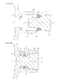
- FIG. 5A is a partially enlarged view of a region T shown in FIG. 4B .
- the filling ratio ⁇ of the O-ring 4 [%] is determined by the following equation (1), wherein: S1 (see FIG. 5A ) is an area of the cross section of the accommodation region F taken along the plane including the central axis X with the insertion member 2 inserted in the reception member 3; S5 is an area of each of the two trapezoids in the cross section of the first back-up ring 5; S6 is an area of each of the two trapezoids in the cross section of the second back-up ring 6; and R is a radius of each of the two circles in the cross section of the O-ring 4 taken along the plane including the central axis X when not pressed from the outside.
- ⁇ ⁇ ⁇ R 2 / S ⁇ 1 - S ⁇ 5 - S ⁇ 6 ⁇ 100
- the area ( ⁇ R 2 ) of the cross section of the O-ring 4 taken along the plane including the central axis X, the area S5 of the cross section of the first back-up ring 5, the area S6 of the cross section of the second back-up ring 6, the outer diameter L22 of the first smaller-diameter columnar portion 22, the inner diameter L31 of the second larger-diameter cylindrical portion 31, a length L73 (see FIG. 5A ) in the axial direction of the accommodation region F are set so that the filling ratio ⁇ of the O-ring 4 is set to not lower than a predetermined value (for example, 60%).
- a predetermined value for example, 60%
- the surface on the insertion member 2 side of the first back-up ring 5 is spaced apart from the outer wall 23b of the insertion member 2 by the distance L72, whereas the surface on the reception member 3 side of the second back-up ring 6 is spaced apart from the inner wall 33b of the reception member 3 by the distance L71.
- the sum of the angles ⁇ 2 and ⁇ 5 and the sum of the angles ⁇ 3 and ⁇ 6 of FIG. 5A are each 90°.
- the O-ring 4 is moved from the insertion member 2 side where the pressure is higher to the reception member 3 side where it is lower.
- the O-ring is brought into contact with the surface on the O-ring 4 side of the second back-up ring 6.
- the second back-up ring 6 is pressed by the O-ring 4, the second back-up ring 6 is moved toward the reception member 3 side (where the pressure is low) by a predetermined amount according to the magnitude of the pressure.
- the movement of the second back-up ring 6 is restricted by the shape of the taper face 33a (shape slant to have a diameter gradually decreasing toward the direction in which the insertion member 2 is fitted into the reception member 3).
- the slant face 61 of the second back-up ring 6 (see FIG. 2 ) is pressed by the taper face 33a inwardly in the radial direction while the inner surface of the second back-up ring 6 is pressed by the outer circumferential surface of the smaller-diameter columnar portion 22 outwardly in the radial direction. Accordingly, the second back-up ring 6 makes close contact with each of the outer circumferential surface of the smaller-diameter columnar portion 22 and the taper face 33a.
- the inner diameter of the larger-diameter cylindrical portion 31 of the reception member 3 is larger than the outer diameter of the smaller-diameter columnar portion 22 of the insertion member 2. Accordingly, the insertion member 2 can be inserted easily into the reception member 3 without the smaller-diameter columnar portion 22 of the insertion member 2 contacting (damaging) the larger-diameter cylindrical portion 31 of the reception member 3.
- the edge of the larger-diameter cylindrical portion 31 of the reception member 3 hits the O-ring 4 fitted on the insertion member 2.
- the O-ring 4 that is made of an elastic material does not damage the edge of and the inner circumferential surface of the larger-diameter cylindrical portion 31 of the reception member 3 even if hitting these.
- the O-ring 4 is elastically deformed by being pressed into the gap between the outer circumferential surface of the smaller-diameter columnar portion 22 and the inner circumferential surface of the larger-diameter cylindrical portion 31, to serve as a guide when the insertion member 2 is inserted into the reception member 3. Accordingly, it is possible to easily fit the insertion member 2 into the reception member 3 with their central axes aligned with each other and prevent damage to the insertion member 2 and the reception member 3.
- the accommodation region F is formed.
- the accommodation region F has inside it the first and second back-up rings 5, 6 arranged in parallel to each other with the O-ring 4 sandwiched therebetween.
- the surface of the first back-up ring 5 opposed to the outer surfaces of the step portion 23 is formed to come in total contact with the outer surfaces of the step portion 23. Accordingly, the first back-up ring 5 makes close contact with the step portion 23 when the pressure inside the accommodation region F becomes higher on the reception member 3 side.
- the surface of the second back-up ring 6 opposed to the inner surfaces of the step portion 33 is formed to come in total contact with the inner surfaces of the step portion 33. Accordingly, the second back-up ring 6 makes close contact with the step portion 33 when the pressure inside the accommodation region F becomes higher on the insertion member 2 side.
- the first back-up ring 5 when the pressure inside the accommodation region F becomes higher on the reception member 3 side, the first back-up ring 5 is deformed along the taper face 23a, presses the taper face 23a inwardly in the radial direction and presses the inner circumferential surface of the larger-diameter cylindrical portion 31 outwardly in the radial direction. Accordingly, the first back-up ring 5 seals the clearance between the first back-up ring 5 and the outer circumferential surface of the insertion member 2 and the clearance between the first back-up ring 5 and the inner circumferential surface of the reception member 3. Consequently, the O-ring can be prevented from being caught in the clearance and damaged to ensure more proper sealing against fluid leakage.
- the surface on the insertion member 2 side of the first back-up ring 5 is spaced apart from the outer wall 23b by the predetermined distance. Accordingly, when the pressure is applied from the reception member 3 side (where the pressure is higher), the first back-up ring 5 is moved toward the insertion member 2 side (where the pressure is lower) according to the magnitude of the pressure. The movement of the first back-up ring 5 is restricted by the shape of the taper face 23a while the first back-up ring 5 makes close contact with each of the taper face 23a and the inner circumferential surface of the larger-diameter cylindrical portion 31 to ensure improved sealing performances. The same holds true for the second back-up ring 6.
- the first back-up ring 5 is moved along the outer circumferential surface of the insertion member 2 of the smaller-diameter columnar portion 22 to reach the taper face 23a.
- the second back-up ring 6 is fitted on the reception member 3, the second back-up ring 6 is moved along the inner circumferential surface of the reception member 3 of the larger-diameter cylindrical portion 31 to reach the taper face 33a.
- the O-ring 4 and the first and second back-up rings 5, 6 can be fitted easily. Further, the first and second back-up rings 5, 6 do not need to be back-up rings with ends for ease of fitting, and can be endless back-up rings.
- the first and second back-up rings 5, 6 can be endless back-up rings, as described above, and are not required to have a double structure. Accordingly, high sealing performances can be exhibited with a simple structure, which reduces manufacturing costs of the sealing structure.
- the filling ratio ⁇ of the O-ring 4 is set to not lower than a predetermined value (for example, 60%). Accordingly, even if an O-ring with a relatively high gas permeation coefficient is used, only a reduced amount of the permeated gas is allowed to stay in a space between the O-ring 4 and the first back-up ring 5 or a space between the O-ring 4 and the second back-up ring 6. Namely, the O-ring 4 prevented from being moved by the pressure of the permeated gas and pressed against either one of the first and second back-up rings on the lower pressure side, and damaged.
- a predetermined value for example, 60%
- an amount of the O-ring 4 to be deformed due to a change in pressure can be reduced, the elasticity of the O-ring 4 required for sealing can be retained sufficiently, and the life of the O-ring 4 can be prolonged.
- the filling ratio ⁇ of the O-ring 4 is set to not lower than the predetermined value, the application range of materials for the O-rings can be broadened.
- the O-ring 4 with a filling ratio ⁇ of not lower than the predetermined value possesses a sufficient force to return to its initial shape (see FIG. 1 ) with the insertion member 2 fitted in the reception member 3.
- the first and second back-up rings 5, 6 each do not need to be a soft back-up ring to serve as a cushion but can be a relatively hard back-up ring.
- the first and second back-up rings 5, 6 that are made of a hard material make close contact with the tapers 23a, 33a, respectively, while sliding thereon in association with application of a pressure to the accommodation region F (see FIG. 5B ), which ensures prevention of fluid leakage from the clearances Y1, Y2 (see FIG. 5A ).
- sealing structure according to an embodiment of the present invention Description has been made of the sealing structure according to an embodiment of the present invention.
- the sealing structure according to the invention is not limited thereto, and various modifications can be made.
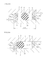
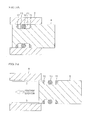
- the sealing structure 1 may be configured so that there is no clearance either between the surface on a insertion member 2A side of a first back-up ring 5A and the outer wall 23b (see FIG. 2 ) or between the surface of a reception member 3A side of a second back-up ring 6A and the inner wall 33b (see FIG. 2 ).
- the sealing structure 1 may be configured so that a first back-up ring 5B and a second back-up ring 6B are shown as right triangles in cross section with the hypotenuses thereof in abutment on the taper of the insertion member 2 and the taper of the reception member 3.
- the sealing structure 1 may be configured so that the insertion member 2 and the reception member 3 have no tapers but they include step faces 23C, 33C extending in parallel to a plane perpendicular to the central axis X, and so that the sealing structure 1 includes a first back-up ring 5C and a second back-up ring 6C that have rectangular cross sections and that make contact with the step faces 23C, 33C, respectively.
- the sealing structure 1 is configured as shown in each of FIGs. 6A-6C , it is possible to fit easily the insertion member 2 into the reception member 3 and prevent damage to the insertion member 2 and the reception member 3. Further, because there are two back-up rings arranged in parallel to each other with the O-ring 4 sandwiched therebetween, a proper sealing is ensured even with application of alternating pressures to prevent damage to the O-ring 4.
- the sealing structure 1 may be configured so that the insertion member 2 and the reception member 3 have no tapers but respectively include step faces 23D, 33D extending in parallel to a plane perpendicular to the central axis X, and so that the sealing structure 1 includes the O-ring 4 but no back-up rings. Even if the sealing structure 1 is configured as shown in FIG. 6D , it is possible to fit easily the insertion member 2 into the reception member 3 and prevent damage to the insertion member 2 and the reception member 3.
- FIG. 5A A proper choice can be made between the configurations of the sealing structures shown in FIG. 5A , FIGs. 6A-6D in consideration of the magnitude of the pressure applied to the accommodation region F, or the like.
- each of the above configurations of the sealing structure 1 in which it is possible to seal the annular clearance between the insertion member 2 and the reception member 3 and thus prevent leakage of the fluid (liquid or gas), is applicable to various apparatus. Further, each of the above configurations of the sealing structure 1 is applicable not only in the case where the relation in magnitude between the pressure from the insertion member 2 side and the pressure from the reception member 3 side are changed with time (namely, alternating pressures are applied) but also in the case where the pressure is always high on either one of the insertion member 2 side and the reception member 3 side.
- the present invention provides a sealing structure that permits easy fitting of the insertion member into the reception member and that prevents damage to the insertion member and the reception member.
- the insertion member includes a first larger-diameter columnar portion, a first smaller-diameter columnar portion, and a first step portion.
- the reception member includes a second larger-diameter cylindrical portion, a second smaller-diameter cylindrical portion, and a second step portion.
- An accommodation region for accommodating an O-ring is defined by an outer circumferential surface of the first smaller-diameter columnar portion, an outer surface of the first step portion, an inner circumferential surface of the second larger-diameter cylindrical portion, and an inner surface of the second step portion.
Landscapes
- Engineering & Computer Science (AREA)
- General Engineering & Computer Science (AREA)
- Mechanical Engineering (AREA)
- Gasket Seals (AREA)
- Pressure Vessels And Lids Thereof (AREA)
Abstract
Description
- This application claims the foreign priority benefit under 35 U.S.C § 119 of Japanese Patent Application No.
2011-204467 filed on September 20, 2011 - The present invention relates to a sealing structure using an O-ring for preventing fluid leakage.
- Various sealing structures have been developed to prevent leakage of hydrogen from a hydrogen tank (storage body) mounted in a fuel cell vehicle that stores high pressure hydrogen inside or prevent leakage of oil from a section of a hydraulically-operated apparatus which makes reciprocating movement.
- For example, the hydrogen tank has a cylindrical outer shape and has an end provided with a cylindrical connector portion (reception member) for a valve body (insertion member) to be inserted in. The connector portion has an inner circumferential surface with an inner threaded portion formed therein. The valve body has an outer circumferential surface with an outer threaded portion formed thereon. When the connector portion is fitted into the valve body by engaging those portions with each other, an annular accommodation region is formed for accommodating an O-ring to prevent leakage of hydrogen from the hydrogen tank. Further, in some cases, a back-up ring or rings are fitted inside the accommodation region to prevent damage to the O-ring caused by the O-ring being caught in a clearance between the connector portion and the valve body.
- Japanese Patent No.
3543617 3543617 - Japanese Unexamined Patent Application Publication No.
2002-161983 2002-161983 - In the sealing devices of Japanese Patent No.
3543617 2002-161983 - For example, in the sealing device (sealing structure) of Japanese Unexamined Patent Application Publication No.
2002-161983 FIG. 7A , a shaft (insertion member) 8 has anannular attachment groove 13. An O-ring 10 and two back-up rings annular attachment groove 13 and then theshaft 8 is inserted into a housing (reception member) 9. - In general, the outer diameter of the
shaft 8 is made slightly smaller than the inner diameter of thehousing 9 in cross section in consideration of ease of fitting of theshaft 8 into thehousing 9 and manufacturing errors. However, it is difficult to insert theshaft 8 into thehousing 9 with the central axes of theshaft 8 and thehousing 9 in complete alignment to prevent the collision of theshaft 8 with thehousing 9. - That is, as shown in
FIG. 7B , when theshaft 8 of the sealing device is fitted into thehousing 9, there is a high risk of the collision of the outer circumferential surface of theshaft 8 with the inner circumferential surface S of thehousing 9, resulting in damage to the outer circumferential surface of theshaft 8 and to the inner circumferential surface S of thehousing 9, that is, damage to a portion of the inner circumferential surface S of thehousing 9 that corresponds to an accommodation region FI for accommodating an O-ring 10. This will cause the problem of insufficient sealing of the clearance by the O-ring 10, resulting in fluid leakage. - It is an object of the present invention to provide a sealing structure that permits easy fitting of the insertion member into the reception member and that prevents damage to the insertion member and the reception member.
- To solve the above problem, the present invention provides a sealing structure comprising:
- an insertion member having a columnar outer shape;
- a reception member having a cylindrical shape for receiving the insertion member, the reception member being formed integrally with a storage body for storing a fluid therein; and
- an O-ring disposed between the insertion member and the reception member for sealing a fluid in the storage body,
- wherein:
- the insertion member includes a first larger-diameter columnar portion, a first smaller-diameter columnar portion, and a first step portion, the first smaller-diameter columnar portion being formed integrally with the first larger-diameter columnar portion and having an outer diameter smaller than an outer diameter of the first larger-diameter columnar portion, the first step portion being formed by a difference in diameter between the first larger-diameter columnar portion and the first smaller-diameter columnar portion,
- the reception member includes a second larger-diameter cylindrical portion, a second smaller-diameter cylindrical portion, and a second step portion, the second larger-diameter cylindrical portion having an inner diameter corresponding to the outer diameter of the first larger-diameter columnar portion, the second smaller-diameter cylindrical portion being formed integrally with the second larger-diameter cylindrical portion and having an inner diameter corresponding to the outer diameter of the first smaller-diameter columnar portion, the second step portion being formed by a difference in diameter between the second larger-diameter cylindrical portion and the second smaller-diameter cylindrical portion, and
- when the insertion member is fitted into and aligned coaxially with the reception member after an end of the first smaller-diameter columnar portion of the insertion member is kept opposed to an end of the second larger-diameter cylindrical portion of the first smaller-diameter columnar portion of the reception member,
- an accommodation region for accommodating the O-ring is formed by an outer circumferential surface of the first smaller-diameter columnar portion, an outer surface of the first step portion, an inner circumferential surface of the second larger-diameter cylindrical portion, and an inner surface of the second step portion.
- With the above arrangement, when the insertion member is inserted into the reception member, the first smaller-diameter columnar portion of the insertion member first enters the space defined by the inner circumferential surface of the second larger-diameter cylindrical portion of the reception member. Here, the inner diameter of the second larger-diameter cylindrical portion of the reception member (an inner diameter L31 to be described later) is larger than the outer diameter of the first smaller-diameter columnar portion of the insertion member (an outer diameter L22 to be described later). Accordingly, the insertion member can be inserted easily into the reception member without the first smaller-diameter columnar portion of the insertion member contacting the inner surface of the second larger-diameter cylindrical portion of the reception member. That is, the outer circumferential surface of the first smaller-diameter columnar portion and the inner circumferential surface of the second larger-diameter cylindrical portion of the reception member are less likely to sustain damage.
- When the insertion member is inserted further into the reception member from the above state, the O-ring is elastically deformed by being pressed into the gap between the outer circumferential surface of the first smaller-diameter columnar portion of the insertion member and the inner circumferential surface of the second larger-diameter cylindrical portion of the reception member. At this time, the magnitudes of the forces by which the outer circumferential surface of the first smaller-diameter columnar portion of the insertion member presses the O-ring in the outward radial directions of the O-ring are uniform throughout the O-ring's annular contact surface with the first smaller-diameter columnar portion. Likewise, the magnitudes of the forces by which the inner circumferential surface of the second larger-diameter cylindrical portion of the reception member presses the O-ring in inward radial directions of the O-ring are uniform throughout the O-ring's annular contact surface with the second larger-diameter cylindrical portion. The O-ring serves as a guide when the insertion member is inserted into the reception member. Accordingly, it is possible to easily fit the
insertion member 2 into thereception member 3 and prevent damage to the outer circumferential surface of the insertion member and to the inner circumferential surface of the reception member. - Further, with the insertion member fitted in the reception member, the accommodation region for accommodating the O-ring is defined by the outer circumferential surface of the first smaller-diameter columnar portion, the outer surfaces of the first step portion, the inner circumferential surface of the second larger-diameter cylindrical portion, and the inner surfaces of the second step portion, and the O-ring is fitted inside the accommodation region. Here, as described above, damage to the outer circumferential surface of the insertion member and to the inner circumferential surface of the reception member is prevented. Accordingly, inside the accommodation region, the O-ring properly presses the outer circumferential surface of the insertion member inwardly in the radial direction while properly pressing the inner circumferential surface of the reception member outwardly in the radial direction, resulting in sealing of the clearance between the insertion member and the reception member. Consequently, it is possible to prevent fluid leakage caused by variations in the pressure from the tank.
- Preferably, the sealing structure is configured so that it further comprises:
- a first back-up ring disposed on a side of the insertion member inside the accommodation region for restricting movement of the O-ring in an axial direction of the accommodation region; and
- a second back-up ring disposed on a side of the reception member inside the accommodation region for restricting movement of the O-ring in the axial direction of the accommodation region,
- wherein:
- the first back-up ring has a surface opposed to the outer surface of the first step portion and formed to come in total contact with the outer surface of the first step portion, and
- the second back-up ring has a surface opposed to the inner surface of the second step portion and formed to come in total contact with the inner surface of the second step portion.
- With the above arrangement, the first back-up ring's surface opposed to the outer surfaces of the first step portion is formed to come in total contact with the outer surfaces of the first step portion. Accordingly, the first back-up ring makes close contact with the first step portion when the pressure inside the accommodation region becomes higher on the reception member side. Likewise, the second back-up ring's surface opposed to the inner surfaces of the second step portion is formed to come in total contact with the inner surfaces of the second step portion. Accordingly, the second back-up ring makes close contact with the second step portion when the pressure inside the accommodation region becomes higher on the insertion member side. Consequently, even when alternating pressures are applied, the back-up rings is deformed in correspondence with the applied alternating pressures to prevent the O-ring from being caught in the clearance between the insertion member and the reception member. Namely, damage to the O-ring can be prevented to ensure more proper sealing against fluid leakage.
- Preferably, the sealing structure is configured so that:
- the outer surface of the first step portion comprises a first taper face tapering down in a direction of insertion of the insertion member further into the reception member, and
- the inner surface of the second step portion comprises a second taper face tapering face tapering down in the direction of insertion of the insertion member further into the reception member.
- With the above arrangement, when the pressure inside the accommodation region becomes higher on the reception member side, the first back-up ring is deformed along the first taper face, presses the first taper inwardly in the radial direction and presses the inner circumferential surface of the second larger-diameter cylindrical portion outwardly in the radial direction. Accordingly, the first back-up ring seals the clearance between the first back-up ring and the outer circumferential surface of the insertion member and the clearance between the first back-up ring and the inner circumferential surface of the reception member. Consequently, the O-ring can be prevented from being caught in the clearance and damaged to ensure more proper sealing against fluid leakage.
- The same holds true for the effects of the second back-up ring in the case in which the pressure is high on the insertion member side.
- Preferably, the sealing structure is configured so that:
- the first step portion includes a first outer wall extending from the first taper face outwardly in the radial direction,
- the second step portion includes a second inner wall extending from the second taper face inwardly in the radial direction, and
- when the insertion member is fitted coaxially into the reception member, clearances are formed respectively between the first back-up ring and the first outer wall and between the second back-up ring and the second inner wall.
- With the above arrangement, a gap is formed between the first back-up ring and the first outer wall. Accordingly, when the pressure becomes higher on the reception member side, the first back-up ring is moved toward the insertion member side by a predetermined distance according to the magnitude of the pressure. The movement of the first back-up ring is restricted by the shape of the first taper face (tapering down in a direction of insertion of the insertion member further into the reception member). The first back-up ring makes close contact with each of the first taper face and the inner circumferential surface of the second larger-diameter cylindrical portion to ensure improved sealing performances. The same holds true for the second back-up ring.
- Preferably, the sealing structure is configured so that:
- respective cross sectional areas of the O-ring, the first back-up ring and the second back-up ring taken along a plane including an axis that the insertion member and the reception member have in common when these members are coaxially fitted with each other, the outer diameter of the first smaller-diameter columnar portion, the inner diameter of the second larger-diameter cylindrical portion, and a length in the axial direction of the accommodation region are set so that a filling ratio of the O-ring in the accommodation region is not lower than a predetermined value.
- With the above arrangement, even if an O-ring with a relatively high gas permeation coefficient is used, a filling ratio of the O-ring in the accommodation region is not lower than a predetermined value. As a result, only a reduced amount of the permeated gas is allowed to stay in a space between the O-ring and the first back-up ring or a space between the O-ring and the second back-up ring. Accordingly, the O-ring is prevented from being moved by the pressure of the permeated gas and pressed against either one of the first and second back-up rings on the lower pressure side, and damaged.
- The present invention provides a sealing structure that permits easy fitting of the insertion member into the reception member and that prevents damage to the insertion member and the reception member.
-
-
FIG. 1 is an exploded schematic view of a sealing structure according an embodiment of the present invention. -
FIG. 2 is a cross sectional exploded view of the sealing structure taken along a plane including a central axis of the sealing structure. -
FIG. 3 is a cross sectional view of the sealing structure taken along the plane including the central axis, showing how a smaller-diameter cylindrical portion of an insertion member enters inside a space defined by an inner circumferential surface of a larger-diameter cylindrical portion of a reception member. -
FIGs. 4A and 4B are cross sectional views of the sealing structure taken along the plane including the central axis:FIG. 4A shows a state in which an O-ring fitted on the insertion member is in contact with an edge of the larger-diameter cylindrical portion of the reception member, andFIG. 4B shows a state in which the insertion member is fitted in the reception member. -
FIG. 5A is a partially enlarged view of a region T shown inFIG. 4B , andFIG. 5B is a partially enlarged view of the region T in a state in which a pressure is applied from the insertion member side. -
FIGs. 6A-6D are partially enlarged views of the region T according to modifications of the present invention.FIG. 6A shows a configuration of the region T with back-up rings shown as trapezoids in cross section and making close contact with the insertion member and the reception member respectively,FIG. 6B shows a configuration of the region T with back-up rings shown as triangles in cross section,FIG. 6C shows a configuration of the region T with back-up rings shown as rectangles in cross section, andFIG. 6D shows a configuration of the region T with no back-up rings but only an O-ring. -
FIGs. 7A and 7B are cross sectional views of a conventional sealing structure.FIG. 7A shows a state in which the insertion member is fitted in the reception member, andFIG. 7B is a state in which the insertion member is being inserted into the reception member. - In the following paragraphs, an embodiment of the present invention will be described in detail with reference to
FIGs. 1-6D . Like components are denoted by like reference numerals and detailed descriptions will be omitted. InFIGs. 1-3 , for the sake of convenience, an O-ring 4 and first and second back-uprings insertion member 2 and areception member 3. -
FIG. 1 is an exploded schematic view of a sealing structure according an embodiment of the present invention.FIG. 2 is a cross sectional view of the sealing structure taken along a plane including a central axis of the sealing structure. As shown inFIG. 1 , a sealing structure 1 includes theinsertion member 2, thereception member 3, the O-ring 4, the first back-upring 5, and the second back-upring 6. - The sealing structure 1 includes the connector portion (reception member 3) of, for example, a hydrogen tank (
tank body 3a: seeFIG. 1 ) and the valve body (insertion member 2) screw-engaged with the connector portion. The sealing structure 1 is for sealing a clearance formed when the connector portion is fitted into the valve body. The hydrogen tank supplies hydrogen to a fuel cell (not shown) where the hydrogen is reacted with oxygen between electrodes to generate electric power. The application of the sealing structure 1, however, is not limited the above example. - In the following paragraphs, "central axis X" refers to a central axis that the
insertion member 2 and thereception member 3 have in common when these members are coaxially fitted with each other. - As shown in
FIG. 1 , theinsertion member 2 includes a larger-diameter columnar portion 21, a smaller-diameter columnar portion 22, and astep portion 23. - The larger-diameter columnar portion 21 (first larger-diameter columnar portion) has a columnar outer shape, and has an outer diameter L21 (see
FIG. 2 ). The larger-diameter columnar portion 21 has, on an end thereof (one end opposite to the other that faces thereception member 3 when theinsertion member 2 is fitted into the reception member 3), an outer threadedportion 24 for engaging theinsertion member 2 with thereception member 3. - The smaller-diameter columnar portion 22 (first smaller-diameter columnar portion) has a columnar outer shape, is formed integrally with the larger-
diameter columnar portion 21, and has an outer diameter L22 (seeFIG. 2 ). Here, the outer diameter L21 of the larger-diameter columnar portion 21 is larger than the outer diameter L22 of the smaller-diameter columnar portion 22. - The step portion 23 (first step portion) is located between the larger-
diameter columnar portion 21 and the smaller-diameter columnar portion 22, and is formed due to the difference in diameter therebetween. Thestep portion 23 has outer surfaces that are respectively ataper face 23a and anouter wall 23b. - The
taper face 23a (first taper face) tapers down in the direction of insertion of theinsertion member 2 further into the reception member 3 (inFIG. 1 , to the left side). Theouter wall 23b (first outer wall) is a ring-shaped surface extending outwardly from thetaper face 23a in the radial direction. - Note that, in
FIG. 1 andFIG. 2 , for the sake of convenience, theinsertion member 2 is shown as having no hole or the like that communicates with the outside, but is not limited thereto. - When the
insertion member 2 functions as a valve body, for example, to be fitted into the connector portion (the reception member 3) of the hydrogen tank (thetank body 3a) supplying a fuel cell (not shown) with hydrogen, theinsertion member 2 is configured as follows. That is, in such a case, theinsertion member 2 includes an electromagnetic solenoid valve (not shown); a hydrogen passage (not shown) through which hydrogen is filled into the hydrogen tank from the outside, or is supplied from the hydrogen tank into the fuel cell; and the like - As shown in
FIG. 1 , thereception member 3 is formed integrally with thetank body 3a (storage body) for storing a fluid therein, and has a larger-diametercylindrical portion 31, a smaller-diametercylindrical portion 32, and astep portion 33. The pressure inside thetank body 3a is higher when the fluid is charged, whereas it is lower when the fluid is discharged. Thus, the so-called alternating pressures are applied to an accommodation region F, which is a region formed when theinsertion member 2 is fitted into thereception member 3, because in the accommodation region F, the pressure is higher on the side of thereception member 3 that is integral with thetank body 3a when the fluid is charged, whereas it is higher on the side of theinsertion member 2 when the fluid is discharged. The accommodation region F will be described later. - The larger-diameter cylindrical portion 31 (second larger-diameter cylindrical portion) has a cylindrical shape, and has an inner diameter L31 (see
FIG. 2 ). Here, the inner diameter L31 corresponds to the outer diameter L21 of the larger-diameter columnar portion 21 of the insertion member 2 (L31≅L21). Note that the inner diameter L31 of the larger-diametercylindrical portion 31 is made slightly larger than the outer diameter L21 of the larger-diameter columnar portion 21 in consideration of ease of fitting of theinsertion member 2 into thereception member 3, manufacturing errors, and the like. The larger-diametercylindrical portion 31 has, on an end thereof (one end opposite to the other that faces theinsertion member 2 when theinsertion member 2 is fitted into the reception member 3), an inner threadedportion 34 for engaging thereception member 3 with theinsertion member 2. - The smaller-diameter cylindrical portion 32 (second smaller-diameter cylindrical portion), has a cylindrical shape, is formed integrally with the larger-diameter
cylindrical portion 31, and has an inner diameter L32 (seeFIG. 2 ). Here, the inner diameter L32 corresponds to the outer diameter L22 of the smaller-diameter columnar portion 22 of the insertion member 2 (L32≅L22). Note that the inner diameter L32 of the smaller-diametercylindrical portion 32 is made slightly larger than the outer diameter L22 of the smaller-diameter columnar portion 22 in consideration of ease of fitting of theinsertion member 2 into thereception member 3, manufacturing errors, and the like. - Accordingly, there are annular clearances (see the clearances Y1, Y2 in
FIG. 5A ) respectively between the outer circumferential surface of the larger-diameter columnar portion 21 and the inner circumferential surface of the larger-diametercylindrical portion 31 and between the outer circumferential surface of the smaller-diameter columnar portion 22 and the inner circumferential surface of the smaller-diametercylindrical portion 32. - The step portion 33 (second step portion) is located between the larger-diameter
cylindrical portion 31 and the smaller-diametercylindrical portion 32, and is formed due to the difference in diameter therebetween. Thestep portion 33 has inner surfaces that are respectively ataper face 33a and aninner wall 33b. - The
taper face 33a (second taper face) tapers down in the direction of insertion of theinsertion member 2 further into the reception member 3 (inFIG. 1 , to the left side). Theinner wall 33b (second inner wall) is a ring-shaped surface extending inwardly from thetaper face 33a in the radial direction. - The O-
ring 4 takes the shape of a ring, and has a cross section of two rings under no external pressure when taken along the plane including the central axis X as shown inFIG. 1 , and is made of a rubber-like elastic material. - The O-
ring 4 has an outer diameter L42 (seeFIG. 2 ) slightly larger than the outer diameter L21 of the larger-diameter columnar portion 21 of the insertion member 2 (seeFIG. 2 ). Further, the O-ring 4 has an inner diameter L41 slightly smaller than the outer diameter L22 of the smaller-diameter columnar portion 22 of the insertion member 2 (seeFIG. 2 ). - That is, the difference between the outer diameter L21 of the larger-
diameter columnar portion 21 and the outer diameter L22 of the smaller-diameter columnar portion 22 (L21-L22) is smaller than the diameter of each circle in the cross section of the O-ring 4 (L42-L41). With theinsertion member 2 fitted in thereception member 3, the O-ring 4 presses the outer circumferential surface of the smaller-diameter columnar portion 22 inwardly in the radial direction while pressing the inner circumferential surface of the larger-diametercylindrical portion 31 outwardly in the radial direction, resulting in proper sealing of the clearance between theinsertion member 2 and thereception member 3. - The first back-up
ring 5 is an endless ring, and, as shown inFIG. 2 , has a vertical cross section of two trapezoids (when taken along the plane including the central axis X). The first back-upring 5 has aslant face 51 on the inside thereof (on the side thereof facing the central axis X). - The first back-up
ring 5 is made of a material such as a fluorocarbon resin, a polyamide resin, a hard rubber or a light metal. Thus, the first back-upring 5 is made of a relatively hard material. Note that there is no need for the back-upring 5 to have a double structure of a hard back-up ring and a soft back-up ring because, as described later, theinsertion member 2 can be passed through the hole of the first back-upring 5 without deforming the first back-upring 5 for the first back-upring 5 to be fitted on theinsertion member 2. - If the back-up
ring 5 is a hard back-up ring with ends, there is a need to provide a soft back-up ring on the O-ring 4 side of the hard back-up ring to prevent the O-ring 4 from being caught in the gap between the ends of the hard back-up ring and damaged. In the present embodiment, in which the first back-upring 5 can be an endless back-up ring, the configuration of the sealing structure 1 can be simplified and the costs can be reduced. - The same holds true for the second back-up
ring 6. - The first back-up
ring 5 has an outer diameter L52 which is approximately equal to the outer diameter L21 of the larger-diameter columnar portion 21 of theinsertion member 2 and which is also approximately equal to the inner diameter L31 of the larger-diametercylindrical portion 31 of the reception member 3 (seeFIG. 2 ). Further, theannular slant face 51 of the first back-upring 5 defines a circle of a diameter L51 at an edge thereof closest to the central axis X. The diameter L51 is approximately equal to the outer diameter L22 of the smaller-diameter columnar portion 22 of theinsertion member 2. - The first back-up
ring 5 has, on theinsertion member 2 side (inFIG. 2 , on the right side), a ring-shaped surface with a length L53 (seeFIG. 2 ) in the radial direction which is larger than a length L23 in the radial direction of theouter wall 23b of theinsertion member 2. - Owing to this structure, when the
insertion member 2 is being fitted into thereception member 3, the first back-upring 5 abuts on thetaper face 23a of theinsertion member 2 before the ring-shaped surface thereof on theinsertion member 2 side comes into contact with theouter wall 23b of theinsertion member 2. This results in the formation of a clearance between the end on theinsertion member 2 side of the first back-upring 5 and theouter wall 23b of the insertion member 2 (see a distance L72 inFIG. 5A ). - The surface of the first back-up
ring 5 opposed to the outer surfaces of thestep portion 23 of theinsertion member 2 is formed to come in total contact with the outer surfaces of thestep portion 23. - That is, the ring-shaped surface on the
insertion member 2 side (inFIG. 2 , on the right side) of the first back-upring 5 forms an angle Θ5 (seeFIG. 5A ) relative to the slant face 51 (seeFIG. 2 ) thereof, whereas thetaper face 23a forms an angle Θ2 relative to the smaller-diameter columnar portion 22 of theinsertion member 2, the sum of the angle Θ5 and the angle Θ2 being 90° (Θ2+Θ5=90°). - Owing to this structure, with the
insertion member 2 fitted in thereception member 3, when the pressure becomes higher inside thestorage body 3a, the first back-upring 5 presses the O-ring 4 inwardly, to prevent the O-ring 4 from being displaced and deformed toward the outer circumferential surface of theinsertion member 2 or toward the inner circumferential surface of thereception member 3. - The same holds true for the relationship between the outer surfaces of the
step portion 33 of thereception member 3 and the surfaces of the second back-upring 6 opposed thereto. - The second back-up
ring 6 is an endless ring, and, as shown inFIG. 2 , is shown as two trapezoids in vertical cross section. The second back-upring 6 has aslant face 61 on the outside thereof (on the side thereof away from the central axis X). The second back-upring 6, like the first back-upring 5, is made of a relatively hard material such as a polyamide resin. - The
annular slant face 61 of the second back-up ring 6 (seeFIG. 2 ) defines a circle of a diameter L62 at an edge thereof most distant from the central axis X. The diameter L62 is approximately equal to the inner diameter L31 of the larger-diametercylindrical portion 31 of thereception member 3. The second back-upring 6 has an inner diameter L61 which is approximately equal to the inner diameter L32 of the smaller-diametercylindrical portion 32 of thereception member 3 and which is also approximately equal to the outer diameter L22 of the smaller-diameter columnar portion 22 of theinsertion member 2. - The second back-up
ring 6 has, on thereception member 3 side (inFIG. 2 , on the left side), a ring-shaped surface with a length L63 (seeFIG. 2 ) in the radial direction which is larger than a length L33 in the radial direction of theouter wall 33b of thereception member 3. - Owing to this structure, when the
insertion member 2 is fitted into thereception member 3, the second back-upring 6 abuts on thetaper face 33a of thereception member 3 before the ring-shaped surface thereof on thereception member 3 side comes into contact with theouter wall 33b of thereception member 3. This results in the formation of a clearance between the end on thereception member 3 side of the second back-upring 6 and theouter wall 33b of the reception member 3 (see a distance L71 inFIG. 5A ). - The surface of the second back-up
ring 6 opposed to the inner surfaces of thestep portion 33 of thereception member 3 is formed to come in total contact with the inner surfaces of thestep portion 33. - That is, the ring-shaped surface on the
reception member 3 side (inFIG. 2 , on the left side) of the second back-upring 6 forms an angle Θ6 (seeFIG. 5A ) relative to the slant face 61 (seeFIG. 2 ) thereof, whereas thetaper face 33a forms an angle Θ3 relative to the larger-diametercylindrical portion 31 of thereception member 3, with the sum of the angle Θ6 and the angle Θ3 being 90° (Θ3+Θ6=90°). - As long as the above conditions are satisfied, the angles Θ5 and Θ6 of
FIG. 5A may be the same or different. For example, the angle Θ5=45° (in this case, Θ2=(90°-Θ5)=45°) and the angle Θ6=60° (in this case, Θ3=(90°-Θ6)=30°). - Before the
insertion member 2 is inserted into thereception member 3, theinsertion member 2 is passed through the hole of the first back-upring 5 as shown inFIG. 3 to make theslant face 51 of the first back-up ring 5 (seeFIG. 2 ) abut on thetaper face 23a of the insertion member 2 (seeFIG. 2 ). At this time, as described above, there is a clearance between the surface on theinsertion member 2 side of the first back-upring 5 and theouter wall 23b of the insertion member 2 (see the distance L72 inFIG. 5A ) - Further, as described above, the sum of the angles Θ2 and Θ5 of
FIG. 5A is 90°. Accordingly, when theslant face 51 of the first back-upring 5 is in abutment on thetaper face 23a of theinsertion member 2, the surface on theinsertion member 2 side of the first back-upring 5 and the surface on thereception member 3 side thereof are parallel to theouter wall 23b of theinsertion member 2. - Next, the
insertion member 2 is passed through the hole of the O-ring 4. As described above, the inner diameter L41 of the O-ring 4 is slightly smaller than the outer diameter L22 of the smaller-diameter columnar portion 22 of the insertion member 2 (seeFIG. 2 ). Accordingly, when the O-ring 4 is fitted on the insertion member 2 (seeFIG. 3 ), the O-ring 4 presses the outer circumferential surface of the smaller-diameter columnar portion 22 inwardly in the radial direction, to fit the O-ring 4 itself in theinsertion member 2 and also prevent the first back-upring 5 from coming off theinsertion member 2. - Note that in the above, it is said that the
slant face 51 of the first back-upring 5 is made to abut on thetaper face 23a of theinsertion member 2, but this is not necessarily the case because even if theslant face 51 of the first back-upring 5 is spaced apart from thetaper face 23a of theinsertion member 2, the first back-upring 5 is pushed by the O-ring 4 when theinsertion member 2 is inserted into thereception member 3 to make theslant face 51 abut on thetaper face 23a. - On the other hand, as shown in
FIG. 3 , the second back-upring 6 is fitted into thereception member 3. That is, the second back-upring 6 is moved to make theslant face 61 thereof (seeFIG. 2 ) abut on thetaper face 33a of the reception member 3 (seeFIG. 2 ). At this time, as described above, there is a clearance between the surface on thereception member 3 side of the second back-upring 6 and theouter wall 33b of the reception member 3 (see the distance L71 inFIG. 5A ). - Further, as described above, the sum of the angles Θ3 and Θ6 of
FIG. 5A is 90°. Accordingly, when theslant face 61 of the second back-upring 6 is in abutment on thetaper face 33a of thereception member 3, the surface on theinsertion member 2 side of the second back-upring 6 and the surface on thereception member 3 side thereof are parallel to theinner wall 33b of thereception member 3. - As described above, the outer diameter L22 of the smaller-
diameter columnar portion 22 of the insertion member 2 (seeFIG. 2 ) is smaller than the inner diameter L31 of the larger-diametercylindrical portion 31 of the reception member 3 (seeFIG. 2 ). This provides an allowance of a distance in the radial direction between theinsertion member 2 and the reception member 3 (L31-L22) when the smaller-diameter columnar portion 22 of theinsertion member 2 enters the space defined by the inner circumferential surface of the larger-diametercylindrical portion 31 of thereception member 3, as shown inFIG. 3 . - Namely, in the state shown in
FIG. 3 , even if theinsertion member 2 is more or less positionally displaced or shifted from thereception member 3 with their central axes misaligned with each other, there is only an extremely small risk that theinsertion member 2 will collide with thereception member 3. Namely, there is only an extremely small risk of damage to the outer circumferential surface of the smaller-diameter columnar portion 22 of theinsertion member 2 and to the inner circumferential surface of the larger-diametercylindrical portion 31 of thereception member 3. - Then, from the state shown in
FIG. 3 , theinsertion member 2 is inserted further into thereception member 3, to the state shown inFIG. 4A . As described above, the outer diameter L42 of the O-ring 4 is only slightly larger than the inner diameter L31 of the larger-diametercylindrical portion 31 of the reception member 3 (seeFIG. 2 ). Thus, as shown inFIG. 4A , the O-ring 4 on theinsertion member 2 contacts the edge of the larger-diametercylindrical portion 31 of thereception member 3. - As described above, the difference (L21-L22) between the outer diameter L21 of the larger-
diameter columnar portion 21 and the outer diameter L22 of the smaller-diameter columnar portion 22 is smaller than the diameter of the circle in the cross section of the O-ring 4 (L42-L41) (seeFIG. 2 ). - Accordingly, when the
insertion member 2 is inserted further into thereception member 3 from the state shown inFIG. 4A , the O-ring 4 is elastically deformed by being pressed into the gap between the outer circumferential surface of the smaller-diameter columnar portion 22 of theinsertion member 2 and the inner circumferential surface of the larger-diametercylindrical portion 31 of thereception member 3. At this time, the magnitudes of the forces by which the outer circumferential surface of the smaller-diameter columnar portion 22 of theinsertion member 2 presses the O-ring in the outward radial directions of the O-ring 4 are uniform throughout the annular contact surface of the O-ring 4 with the smaller-diameter columnar portion 22. Likewise, the magnitudes of the forces by which the inner circumferential surface of the larger-diametercylindrical portion 31 of thereception member 3 presses the O-ring 4 in inward radial directions of the O-ring 4 are uniform throughout the annular contact surface of the O-ring 4 with the larger-diametercylindrical portion 31. - Accordingly, when the
insertion member 2 is inserted further into thereception member 3 from the state shown inFIG. 4A , the O-ring 4 is used as a guide to make it difficult for the central axis of theinsertion member 2 to be misaligned with that of thereception member 3. - Note that, as shown in
FIG. 3 , the sum of the length L24 in the axial direction of the smaller-diameter columnar portion 22 and the length L25 in the axial direction of the step portion 23 (L24+L25) is preferably smaller than the sum of the length L34 in the axial direction of the larger-diametercylindrical portion 31 and the length L35 in the axial direction of the step portion 33 (L34+L35). - In such a case, the end on the
reception member 3 side of the larger-diameter columnar portion 21 (seeFIG. 2 ) enters the space defined by the inner circumferential surface of the larger-diametercylindrical portion 31 before the end of the smaller-diameter columnar portion 22 of theinsertion member 2 reaches the end on theinsertion member 2 side of the smaller-diametercylindrical portion 32 of thereception member 3. - Here, as described above, the outer diameter L21 of the larger-
diameter columnar portion 21 of theinsertion member 2 is approximately equal to the inner diameter L31 of the larger-diametercylindrical portion 31 of thereception member 3. Theinsertion member 2 is inserted into thereception member 3 with the aid of the O-ring 4 that serves as a guide by traveling through the gap between the smaller-diameter columnar portion 22 of theinsertion member 2 and the larger-diametercylindrical portion 31 of thereception member 3. Then, as described above, when the end on thereception member 3 side of the larger-diameter columnar portion 21 (seeFIG. 2 ) enters the space defined by the inner circumferential surface of the larger-diametercylindrical portion 31, the central axis of theinsertion member 2 is approximately aligned with that of thereception member 3. - The
insertion member 2 is inserted further into thereception member 3 while being centered in relation thereto with the central axis of theinsertion member 2 approximately aligned with that of thereception member 3 as described above until the end of the smaller-diameter columnar portion 22 of theinsertion member 2 enters the space defined by the smaller-diametercylindrical portion 32 of thereception member 3. At this time, because theinsertion member 2 is centered in relation to thereception member 3 as described above, theinsertion member 2 can be fitted smoothly into thereception member 3 without the outer circumferential surface of the smaller-diameter columnar portion 22 damaging the inner circumferential surface of the smaller-diametercylindrical portion 32. - Then, the outer threaded
portion 24 of the larger-diameter columnar portion 21 of theinsertion member 2 is engaged with the inner threadedportion 34 of the larger-diametercylindrical portion 31 of thereception member 3 to fit theinsertion member 2 in thereception member 3 as in the state shown inFIG. 4B . - As shown in
FIG. 4B , with theinsertion member 2 fitted in thereception member 3, the accommodation region F for accommodating the O-ring 4 is defined by the outer circumferential surface of the smaller-diameter columnar portion 22, the outer surfaces of thestep portion 23, the inner circumferential surface of the larger-diametercylindrical portion 31, and the inner surfaces of thestep portion 33. Inside the accommodation region F, the O-ring 4 is located between the first back-upring 5 and the second back-upring 6. -
FIG. 5A is a partially enlarged view of a region T shown inFIG. 4B . - The filling ratio α of the O-ring 4 [%] is determined by the following equation (1), wherein: S1 (see
FIG. 5A ) is an area of the cross section of the accommodation region F taken along the plane including the central axis X with theinsertion member 2 inserted in thereception member 3; S5 is an area of each of the two trapezoids in the cross section of the first back-upring 5; S6 is an area of each of the two trapezoids in the cross section of the second back-upring 6; and R is a radius of each of the two circles in the cross section of the O-ring 4 taken along the plane including the central axis X when not pressed from the outside.
- In the sealing structure 1 according to the present embodiment, the area (πR2) of the cross section of the O-
ring 4 taken along the plane including the central axis X, the area S5 of the cross section of the first back-upring 5, the area S6 of the cross section of the second back-upring 6, the outer diameter L22 of the first smaller-diameter columnar portion 22, the inner diameter L31 of the second larger-diametercylindrical portion 31, a length L73 (seeFIG. 5A ) in the axial direction of the accommodation region F are set so that the filling ratio α of the O-ring 4 is set to not lower than a predetermined value (for example, 60%). - As shown in
FIG. 5A , there are small annular clearances Y1, Y2 between the outer circumferential surface of the larger-diameter columnar portion 21 and the inner circumferential surface of the larger-diametercylindrical portion 31 and between the outer circumferential surface of the smaller-diameter columnar portion 22 and the inner circumferential surface of the smaller-diametercylindrical portion 32. - Further, as shown in
FIG. 5A , the surface on theinsertion member 2 side of the first back-upring 5 is spaced apart from theouter wall 23b of theinsertion member 2 by the distance L72, whereas the surface on thereception member 3 side of the second back-upring 6 is spaced apart from theinner wall 33b of thereception member 3 by the distance L71. - As mentioned above, the sum of the angles Θ2 and Θ5 and the sum of the angles Θ3 and Θ6 of
FIG. 5A are each 90°. - For example, as shown in
FIG. 5B , when the pressure inside thestorage body 3a becomes lower and a pressure P is applied to the inside of thestorage body 3a from theinsertion member 2 side, the O-ring 4 is moved from theinsertion member 2 side where the pressure is higher to thereception member 3 side where it is lower. The O-ring is brought into contact with the surface on the O-ring 4 side of the second back-upring 6. Further, when the second back-upring 6 is pressed by the O-ring 4, the second back-upring 6 is moved toward thereception member 3 side (where the pressure is low) by a predetermined amount according to the magnitude of the pressure. The movement of the second back-upring 6 is restricted by the shape of thetaper face 33a (shape slant to have a diameter gradually decreasing toward the direction in which theinsertion member 2 is fitted into the reception member 3). - Namely, the
slant face 61 of the second back-up ring 6 (seeFIG. 2 ) is pressed by thetaper face 33a inwardly in the radial direction while the inner surface of the second back-upring 6 is pressed by the outer circumferential surface of the smaller-diameter columnar portion 22 outwardly in the radial direction. Accordingly, the second back-upring 6 makes close contact with each of the outer circumferential surface of the smaller-diameter columnar portion 22 and thetaper face 33a. - In the above, description has been made of the case in which the pressure P is applied from the
insertion member 2 side. When the pressure inside thestorage body 3a becomes higher and the pressure is applied from thereception member 3 side, on the other hand, the first back-upring 5 is moved toward theinsertion member 2 side (where the pressure is lower) according to the magnitude of the pressure. The description of this case that will be the same as the above will be omitted. - According to the sealing structure 1 of the present embodiment, the following effects can be obtained.
- That is, the inner diameter of the larger-diameter
cylindrical portion 31 of thereception member 3 is larger than the outer diameter of the smaller-diameter columnar portion 22 of theinsertion member 2. Accordingly, theinsertion member 2 can be inserted easily into thereception member 3 without the smaller-diameter columnar portion 22 of theinsertion member 2 contacting (damaging) the larger-diametercylindrical portion 31 of thereception member 3. - When from the above state, the
insertion member 2 is inserted further into thereception member 3, the edge of the larger-diametercylindrical portion 31 of thereception member 3 hits the O-ring 4 fitted on theinsertion member 2. The O-ring 4 that is made of an elastic material does not damage the edge of and the inner circumferential surface of the larger-diametercylindrical portion 31 of thereception member 3 even if hitting these. - Then, when from the above state, the
insertion member 2 is inserted further into thereception member 3, the O-ring 4 is elastically deformed by being pressed into the gap between the outer circumferential surface of the smaller-diameter columnar portion 22 and the inner circumferential surface of the larger-diametercylindrical portion 31, to serve as a guide when theinsertion member 2 is inserted into thereception member 3. Accordingly, it is possible to easily fit theinsertion member 2 into thereception member 3 with their central axes aligned with each other and prevent damage to theinsertion member 2 and thereception member 3. - Further, with the insertion member fitted in the
reception member 3, the accommodation region F is formed. The accommodation region F has inside it the first and second back-uprings ring 4 sandwiched therebetween. Thus, even when alternating pressures are applied to the accommodation region F, the O-ring 4 can be protected properly to ensure improved sealing performances. - The surface of the first back-up
ring 5 opposed to the outer surfaces of thestep portion 23 is formed to come in total contact with the outer surfaces of thestep portion 23. Accordingly, the first back-upring 5 makes close contact with thestep portion 23 when the pressure inside the accommodation region F becomes higher on thereception member 3 side. Likewise, the surface of the second back-upring 6 opposed to the inner surfaces of thestep portion 33 is formed to come in total contact with the inner surfaces of thestep portion 33. Accordingly, the second back-upring 6 makes close contact with thestep portion 33 when the pressure inside the accommodation region F becomes higher on theinsertion member 2 side. Consequently, even when alternating pressures are applied, the O-ring 4 is prevented from being caught in the clearances Y1, Y2 between theinsertion member 2 and thereception member 3. Namely, damage to the O-ring 4 can be prevented to ensure more proper sealing against fluid leakage. - Moreover, for example, when the pressure inside the accommodation region F becomes higher on the
reception member 3 side, the first back-upring 5 is deformed along thetaper face 23a, presses thetaper face 23a inwardly in the radial direction and presses the inner circumferential surface of the larger-diametercylindrical portion 31 outwardly in the radial direction. Accordingly, the first back-upring 5 seals the clearance between the first back-upring 5 and the outer circumferential surface of theinsertion member 2 and the clearance between the first back-upring 5 and the inner circumferential surface of thereception member 3. Consequently, the O-ring can be prevented from being caught in the clearance and damaged to ensure more proper sealing against fluid leakage. - The same holds true for the effects of the second back-up ring in the case in which the pressure is high on the
insertion member 2 side. - Further, the surface on the
insertion member 2 side of the first back-upring 5 is spaced apart from theouter wall 23b by the predetermined distance. Accordingly, when the pressure is applied from thereception member 3 side (where the pressure is higher), the first back-upring 5 is moved toward theinsertion member 2 side (where the pressure is lower) according to the magnitude of the pressure. The movement of the first back-upring 5 is restricted by the shape of thetaper face 23a while the first back-upring 5 makes close contact with each of thetaper face 23a and the inner circumferential surface of the larger-diametercylindrical portion 31 to ensure improved sealing performances. The same holds true for the second back-upring 6. - Further, when the
insertion member 2 is passed through the hole of the first back-upring 5 for the first back-upring 5 to be fitted on theinsertion member 2, the first back-upring 5 is moved along the outer circumferential surface of theinsertion member 2 of the smaller-diameter columnar portion 22 to reach thetaper face 23a. The same holds true for how to fit the O-ring 4. Further, when the second back-upring 6 is fitted on thereception member 3, the second back-upring 6 is moved along the inner circumferential surface of thereception member 3 of the larger-diametercylindrical portion 31 to reach thetaper face 33a. - Therefore, according to the sealing structure 1 of the present embodiment, the O-
ring 4 and the first and second back-uprings rings - If a back-up ring with ends is used for sealing a high-pressure gas, it is necessary to use a back-up ring with a double-structure of a hard back-up ring with ends and a soft back-up ring with ends to prevent gas leakage from the ends and prevent damage to the O-
ring 4. This results in a complicated sealing structure and increased costs. - On the other hand, according to the sealing structure 1 of the present embodiment, the first and second back-up
rings - Further, in the sealing structure 1 according to the present embodiment, the filling ratio α of the O-
ring 4 is set to not lower than a predetermined value (for example, 60%). Accordingly, even if an O-ring with a relatively high gas permeation coefficient is used, only a reduced amount of the permeated gas is allowed to stay in a space between the O-ring 4 and the first back-upring 5 or a space between the O-ring 4 and the second back-upring 6. Namely, the O-ring 4 prevented from being moved by the pressure of the permeated gas and pressed against either one of the first and second back-up rings on the lower pressure side, and damaged. - Further, an amount of the O-
ring 4 to be deformed due to a change in pressure can be reduced, the elasticity of the O-ring 4 required for sealing can be retained sufficiently, and the life of the O-ring 4 can be prolonged. - Moreover, by setting the filling ratio α of the O-
ring 4 to not lower than the predetermined value, the application range of materials for the O-rings can be broadened. - Further, the O-
ring 4 with a filling ratio α of not lower than the predetermined value possesses a sufficient force to return to its initial shape (seeFIG. 1 ) with theinsertion member 2 fitted in thereception member 3. Accordingly, the first and second back-uprings - The first and second back-up
rings tapers FIG. 5B ), which ensures prevention of fluid leakage from the clearances Y1, Y2 (seeFIG. 5A ). - Description has been made of the sealing structure according to an embodiment of the present invention. However, the sealing structure according to the invention is not limited thereto, and various modifications can be made.
- For example, as shown in
FIG. 6A , the sealing structure 1 may be configured so that there is no clearance either between the surface on ainsertion member 2A side of a first back-upring 5A and theouter wall 23b (seeFIG. 2 ) or between the surface of areception member 3A side of a second back-upring 6A and theinner wall 33b (seeFIG. 2 ). - Further, as shown in
FIG. 6B , the sealing structure 1 may be configured so that a first back-upring 5B and a second back-upring 6B are shown as right triangles in cross section with the hypotenuses thereof in abutment on the taper of theinsertion member 2 and the taper of thereception member 3. - Further, as shown in
FIG. 6C , the sealing structure 1 may be configured so that theinsertion member 2 and thereception member 3 have no tapers but they include step faces 23C, 33C extending in parallel to a plane perpendicular to the central axis X, and so that the sealing structure 1 includes a first back-upring 5C and a second back-upring 6C that have rectangular cross sections and that make contact with the step faces 23C, 33C, respectively. - Even if the sealing structure 1 is configured as shown in each of
FIGs. 6A-6C , it is possible to fit easily theinsertion member 2 into thereception member 3 and prevent damage to theinsertion member 2 and thereception member 3. Further, because there are two back-up rings arranged in parallel to each other with the O-ring 4 sandwiched therebetween, a proper sealing is ensured even with application of alternating pressures to prevent damage to the O-ring 4. - Moreover, as shown in
FIG. 6D , the sealing structure 1 may be configured so that theinsertion member 2 and thereception member 3 have no tapers but respectively include step faces 23D, 33D extending in parallel to a plane perpendicular to the central axis X, and so that the sealing structure 1 includes the O-ring 4 but no back-up rings. Even if the sealing structure 1 is configured as shown inFIG. 6D , it is possible to fit easily theinsertion member 2 into thereception member 3 and prevent damage to theinsertion member 2 and thereception member 3. - A proper choice can be made between the configurations of the sealing structures shown in
FIG. 5A ,FIGs. 6A-6D in consideration of the magnitude of the pressure applied to the accommodation region F, or the like. - Moreover, each of the above configurations of the sealing structure 1, in which it is possible to seal the annular clearance between the
insertion member 2 and thereception member 3 and thus prevent leakage of the fluid (liquid or gas), is applicable to various apparatus. Further, each of the above configurations of the sealing structure 1 is applicable not only in the case where the relation in magnitude between the pressure from theinsertion member 2 side and the pressure from thereception member 3 side are changed with time (namely, alternating pressures are applied) but also in the case where the pressure is always high on either one of theinsertion member 2 side and thereception member 3 side. - The present invention provides a sealing structure that permits easy fitting of the insertion member into the reception member and that prevents damage to the insertion member and the reception member.
- The insertion member includes a first larger-diameter columnar portion, a first smaller-diameter columnar portion, and a first step portion.
- The reception member includes a second larger-diameter cylindrical portion, a second smaller-diameter cylindrical portion, and a second step portion.
- An accommodation region for accommodating an O-ring is defined by an outer circumferential surface of the first smaller-diameter columnar portion, an outer surface of the first step portion, an inner circumferential surface of the second larger-diameter cylindrical portion, and an inner surface of the second step portion.
Claims (5)
- A sealing structure comprising:an insertion member having a columnar outer shape;a reception member having a cylindrical shape for receiving the insertion member, the reception member being formed integrally with a storage body for storing a fluid therein; andan O-ring disposed between the insertion member and the reception member for sealing a fluid in the storage body,wherein:the insertion member includes a first larger-diameter columnar portion, a first smaller-diameter columnar portion, and a first step portion, the first smaller-diameter columnar portion being formed integrally with the first larger-diameter columnar portion and having an outer diameter smaller than an outer diameter of the first larger-diameter columnar portion, the first step portion being formed by a difference in diameter between the first larger-diameter columnar portion and the first smaller-diameter columnar portion,the reception member includes a second larger-diameter cylindrical portion, a second smaller-diameter cylindrical portion, and a second step portion, the second larger-diameter cylindrical portion having an inner diameter corresponding to the outer diameter of the first larger-diameter columnar portion, the second smaller-diameter cylindrical portion being formed integrally with the second larger-diameter cylindrical portion and having an inner diameter corresponding to the outer diameter of the first smaller-diameter columnar portion, the second step portion being formed by a difference in diameter between the second larger-diameter cylindrical portion and the second smaller-diameter cylindrical portion, andwhen the insertion member is fitted into and aligned coaxially with the reception member after an end of the first smaller-diameter columnar portion of the insertion member is kept opposed to an end of the second larger-diameter cylindrical portion of the first smaller-diameter columnar portion of the reception member,an accommodation region for accommodating the O-ring is formed by an outer circumferential surface of the first smaller-diameter columnar portion, an outer surface of the first step portion, an inner circumferential surface of the second larger-diameter cylindrical portion, and an inner surface of the second step portion.
- The sealing structure of Claim 1, further comprising:a first back-up ring disposed on a side of the insertion member inside the accommodation region for restricting movement of the O-ring in an axial direction of the accommodation region; anda second back-up ring disposed on a side of the reception member inside the accommodation region for restricting movement of the O-ring in the axial direction of the accommodation region,wherein:the first back-up ring has a surface opposed to the outer surface of the first step portion and formed to come in total contact with the outer surface of the first step portion, andthe second back-up ring has a surface opposed to the inner surface of the second step portion and formed to come in total contact with the inner surface of the second step portion.
- The sealing structure of Claim 2, wherein:the outer surface of the first step portion comprises a first taper face tapering down in a direction of insertion of the insertion member further into the reception member, andthe inner surface of the second step portion comprises a second taper face tapering face tapering down in the direction of insertion of the insertion member further into the reception member.
- The sealing structure of Claim 3, wherein:the first step portion includes a first outer wall extending from the first taper face outwardly in the radial direction,the second step portion includes a second inner wall extending from the second taper face inwardly in the radial direction, andwhen the insertion member is fitted coaxially into the reception member, clearances are formed respectively between the first back-up ring and the first outer wall and between the second back-up ring and the second inner wall.
- The sealing structure of any one of Claims 2-4, wherein:respective cross sectional areas of the O-ring, the first back-up ring and the second back-up ring taken along a plane including an axis that the insertion member and the reception member have in common when these members are coaxially fitted with each other, the outer diameter of the first smaller-diameter columnar portion, the inner diameter of the second larger-diameter cylindrical portion, and a length in the axial direction of the accommodation region are set so that a filling ratio of the O-ring in the accommodation region is not lower than a predetermined value.
Applications Claiming Priority (1)
| Application Number | Priority Date | Filing Date | Title |
|---|---|---|---|
| JP2011204467A JP5458076B2 (en) | 2011-09-20 | 2011-09-20 | Sealing structure |
Publications (2)
| Publication Number | Publication Date |
|---|---|
| EP2573432A1 true EP2573432A1 (en) | 2013-03-27 |
| EP2573432B1 EP2573432B1 (en) | 2014-05-14 |
Family
ID=47008314
Family Applications (1)
| Application Number | Title | Priority Date | Filing Date |
|---|---|---|---|
| EP12185151.3A Not-in-force EP2573432B1 (en) | 2011-09-20 | 2012-09-20 | Sealing structure |
Country Status (4)
| Country | Link |
|---|---|
| US (1) | US9243713B2 (en) |
| EP (1) | EP2573432B1 (en) |
| JP (1) | JP5458076B2 (en) |
| CN (1) | CN103016738B (en) |
Families Citing this family (12)
| Publication number | Priority date | Publication date | Assignee | Title |
|---|---|---|---|---|
| US20150285230A1 (en) * | 2014-04-07 | 2015-10-08 | Halla Visteon Climate Control Corp. | Seal structure for a rotary valve compressor |
| US10107401B2 (en) * | 2014-09-24 | 2018-10-23 | Nok Corporation | Sealing structure |
| KR20160046612A (en) * | 2014-10-21 | 2016-04-29 | 삼성전자주식회사 | Case housing electric parts therein and electronic device using the same |
| JP6423405B2 (en) * | 2016-11-01 | 2018-11-14 | 有限会社飯田製作所 | Seal structure and manufacturing method thereof |
| JP6487478B2 (en) * | 2017-03-15 | 2019-03-20 | 本田技研工業株式会社 | High pressure tank |
| CN109307074B (en) * | 2017-07-26 | 2020-11-17 | 中航光电科技股份有限公司 | Sealing structure and high-pressure connector using same |
| JP6807891B2 (en) * | 2018-04-16 | 2021-01-06 | 豊田合成株式会社 | High pressure tank seal structure |
| JP7243978B2 (en) * | 2019-01-23 | 2023-03-22 | 株式会社荒井製作所 | sealing device |
| KR102778276B1 (en) * | 2020-03-02 | 2025-03-12 | 현대자동차주식회사 | Hydrogen supply apparatus and sealing unit using the same |
| EP4271932A4 (en) * | 2021-02-05 | 2024-12-04 | Cryoport, Inc. | TAPERED STEAM PLUG |
| JPWO2023085164A1 (en) * | 2021-11-12 | 2023-05-19 | ||
| JP7670045B2 (en) * | 2022-11-22 | 2025-04-30 | トヨタ自動車株式会社 | High Pressure Tank |
Citations (4)
| Publication number | Priority date | Publication date | Assignee | Title |
|---|---|---|---|---|
| JP2002161983A (en) | 2000-11-24 | 2002-06-07 | Nok Corp | Sealing device |
| JP3543617B2 (en) | 1998-04-30 | 2004-07-14 | Nok株式会社 | Sealing device |
| US20050046187A1 (en) * | 2003-07-29 | 2005-03-03 | Masayuki Takeuchi | Pipe joint for refrigeration cycle having combination of O-ring and backup ring |
| EP1950472A1 (en) * | 2005-11-14 | 2008-07-30 | NOK Corporation | Sealing device |
Family Cites Families (22)
| Publication number | Priority date | Publication date | Assignee | Title |
|---|---|---|---|---|
| US2420104A (en) | 1943-07-22 | 1947-05-06 | Maytag Co | Seal guard ring |
| US2462586A (en) * | 1946-01-02 | 1949-02-22 | New York Air Brake Co | Seal for resisting high pressures |
| US3004783A (en) | 1957-08-12 | 1961-10-17 | Houston Engineers Inc | High pressure packing means |
| US2961278A (en) * | 1959-01-02 | 1960-11-22 | Harwood Engineering Company | High pressure piston seal |
| US3094337A (en) * | 1960-10-31 | 1963-06-18 | Universal Packing & Gasket Com | Seal ring |
| US3144162A (en) * | 1961-08-14 | 1964-08-11 | Bethlehem Steel Corp | Closure for a pressure vessel |
| US3514132A (en) | 1968-06-10 | 1970-05-26 | Perry Oceanographics Inc | Pressure vessel connection |
| US3767215A (en) * | 1972-09-01 | 1973-10-23 | Us Navy | Multi-ring hydraulic seal for irregular bore surfaces |
| US3888496A (en) * | 1973-05-03 | 1975-06-10 | Shamban & Co W S | Captive seal with retainers loaded against non-parallel surfaces |
| FR2286990A1 (en) * | 1974-10-04 | 1976-04-30 | Anvar | WATERPROOFING DEVICE |
| US4572239A (en) * | 1981-08-28 | 1986-02-25 | Whitey Co. | High pressure ball valve |
| US4556227A (en) | 1984-10-01 | 1985-12-03 | Kabushiki Kaisha Suiken | Universal pipe joint assembly |
| JPH01165856A (en) | 1987-12-21 | 1989-06-29 | Kajima Corp | Connecting structure of pc steel bar and fiber-reinforced plastic bar |
| JPH01165856U (en) * | 1988-05-16 | 1989-11-20 | ||
| JP2683285B2 (en) * | 1989-10-13 | 1997-11-26 | 日本鋳鉄管株式会社 | Pipe fitting structure |
| US6758478B1 (en) * | 2003-01-10 | 2004-07-06 | Delphi Technologies, Inc. | Elastomeric seal anti-extrusion wedge backup ring and flange |
| JP4096832B2 (en) * | 2003-07-22 | 2008-06-04 | 株式会社デンソー | Piping joint for refrigeration cycle |
| US7793944B2 (en) * | 2004-12-28 | 2010-09-14 | Nok Corporation | Sealing device |
| JP4877474B2 (en) * | 2005-11-14 | 2012-02-15 | Nok株式会社 | Sealing device for carbon dioxide gas seal |
| JP2008304012A (en) * | 2007-06-08 | 2008-12-18 | Nsk Ltd | Ball screw device |
| US7828301B2 (en) | 2008-01-25 | 2010-11-09 | Intelliserv, Llc | Self-energized backup ring for annular seals |
| JP5374559B2 (en) * | 2011-09-20 | 2013-12-25 | 本田技研工業株式会社 | Sealing structure |
-
2011
- 2011-09-20 JP JP2011204467A patent/JP5458076B2/en not_active Expired - Fee Related
-
2012
- 2012-09-20 CN CN201210352088.4A patent/CN103016738B/en active Active
- 2012-09-20 US US13/623,391 patent/US9243713B2/en active Active
- 2012-09-20 EP EP12185151.3A patent/EP2573432B1/en not_active Not-in-force
Patent Citations (4)
| Publication number | Priority date | Publication date | Assignee | Title |
|---|---|---|---|---|
| JP3543617B2 (en) | 1998-04-30 | 2004-07-14 | Nok株式会社 | Sealing device |
| JP2002161983A (en) | 2000-11-24 | 2002-06-07 | Nok Corp | Sealing device |
| US20050046187A1 (en) * | 2003-07-29 | 2005-03-03 | Masayuki Takeuchi | Pipe joint for refrigeration cycle having combination of O-ring and backup ring |
| EP1950472A1 (en) * | 2005-11-14 | 2008-07-30 | NOK Corporation | Sealing device |
Also Published As
| Publication number | Publication date |
|---|---|
| US20130069362A1 (en) | 2013-03-21 |
| CN103016738B (en) | 2015-09-30 |
| JP2013064471A (en) | 2013-04-11 |
| EP2573432B1 (en) | 2014-05-14 |
| US9243713B2 (en) | 2016-01-26 |
| JP5458076B2 (en) | 2014-04-02 |
| CN103016738A (en) | 2013-04-03 |
Similar Documents
| Publication | Publication Date | Title |
|---|---|---|
| EP2573432B1 (en) | Sealing structure | |
| EP2372208B1 (en) | Threaded joint with elastomeric seal flange | |
| US9157530B2 (en) | Sealing device and sealing structure | |
| US9851028B2 (en) | Coupling and joint for fixedly and sealingly securing components to one another | |
| US6854486B2 (en) | Fluid line assembly | |
| CN103016739B (en) | seal structure | |
| US9702463B2 (en) | Seal device | |
| US20050082764A1 (en) | Seal retainer with pressure energized metal seal members for undersea hydraulic coupling | |
| JP2008267449A (en) | Backup ring | |
| JP5503704B2 (en) | Sealing structure | |
| EP3067592A1 (en) | Gasket and sealing structure | |
| EP1832787A1 (en) | Sealing device | |
| EP1679458B1 (en) | Seal structure for gas | |
| US6431553B1 (en) | Radially pressure balanced floating seal system | |
| KR20210084217A (en) | Tube connector | |
| EP1950473A1 (en) | Carbon dioxide gas sealing enclosed device | |
| JP2008008318A (en) | Annular seal member and mechanical seal | |
| JP6941025B2 (en) | Sealing structure and sealing member for male and female threads | |
| EP2836747A1 (en) | Variable structure seals | |
| EP4600502A1 (en) | Hydraulic actuator | |
| US20250060004A1 (en) | Rolling bearing | |
| JP2025059269A (en) | Pipe joint and manufacturing method thereof | |
| MXPA03001489A (en) | Improved mechanical face seal. |
Legal Events
| Date | Code | Title | Description |
|---|---|---|---|
| PUAI | Public reference made under article 153(3) epc to a published international application that has entered the european phase |
Free format text: ORIGINAL CODE: 0009012 |
|
| 17P | Request for examination filed |
Effective date: 20120920 |
|
| AK | Designated contracting states |
Kind code of ref document: A1 Designated state(s): AL AT BE BG CH CY CZ DE DK EE ES FI FR GB GR HR HU IE IS IT LI LT LU LV MC MK MT NL NO PL PT RO RS SE SI SK SM TR |
|
| AX | Request for extension of the european patent |
Extension state: BA ME |
|
| GRAP | Despatch of communication of intention to grant a patent |
Free format text: ORIGINAL CODE: EPIDOSNIGR1 |
|
| INTG | Intention to grant announced |
Effective date: 20140117 |
|
| GRAS | Grant fee paid |
Free format text: ORIGINAL CODE: EPIDOSNIGR3 |
|
| GRAA | (expected) grant |
Free format text: ORIGINAL CODE: 0009210 |
|
| AK | Designated contracting states |
Kind code of ref document: B1 Designated state(s): AL AT BE BG CH CY CZ DE DK EE ES FI FR GB GR HR HU IE IS IT LI LT LU LV MC MK MT NL NO PL PT RO RS SE SI SK SM TR |
|
| REG | Reference to a national code |
Ref country code: GB Ref legal event code: FG4D |
|
| REG | Reference to a national code |
Ref country code: AT Ref legal event code: REF Ref document number: 668543 Country of ref document: AT Kind code of ref document: T Effective date: 20140615 |
|
| REG | Reference to a national code |
Ref country code: IE Ref legal event code: FG4D |
|
| REG | Reference to a national code |
Ref country code: DE Ref legal event code: R096 Ref document number: 602012001755 Country of ref document: DE Effective date: 20140626 |
|
| REG | Reference to a national code |
Ref country code: NL Ref legal event code: VDEP Effective date: 20140514 Ref country code: AT Ref legal event code: MK05 Ref document number: 668543 Country of ref document: AT Kind code of ref document: T Effective date: 20140514 |
|
| REG | Reference to a national code |
Ref country code: LT Ref legal event code: MG4D |
|
| PG25 | Lapsed in a contracting state [announced via postgrant information from national office to epo] |
Ref country code: FI Free format text: LAPSE BECAUSE OF FAILURE TO SUBMIT A TRANSLATION OF THE DESCRIPTION OR TO PAY THE FEE WITHIN THE PRESCRIBED TIME-LIMIT Effective date: 20140514 Ref country code: CY Free format text: LAPSE BECAUSE OF FAILURE TO SUBMIT A TRANSLATION OF THE DESCRIPTION OR TO PAY THE FEE WITHIN THE PRESCRIBED TIME-LIMIT Effective date: 20140514 Ref country code: NO Free format text: LAPSE BECAUSE OF FAILURE TO SUBMIT A TRANSLATION OF THE DESCRIPTION OR TO PAY THE FEE WITHIN THE PRESCRIBED TIME-LIMIT Effective date: 20140814 Ref country code: IS Free format text: LAPSE BECAUSE OF FAILURE TO SUBMIT A TRANSLATION OF THE DESCRIPTION OR TO PAY THE FEE WITHIN THE PRESCRIBED TIME-LIMIT Effective date: 20140914 Ref country code: GR Free format text: LAPSE BECAUSE OF FAILURE TO SUBMIT A TRANSLATION OF THE DESCRIPTION OR TO PAY THE FEE WITHIN THE PRESCRIBED TIME-LIMIT Effective date: 20140815 Ref country code: LT Free format text: LAPSE BECAUSE OF FAILURE TO SUBMIT A TRANSLATION OF THE DESCRIPTION OR TO PAY THE FEE WITHIN THE PRESCRIBED TIME-LIMIT Effective date: 20140514 |
|
| PG25 | Lapsed in a contracting state [announced via postgrant information from national office to epo] |
Ref country code: ES Free format text: LAPSE BECAUSE OF FAILURE TO SUBMIT A TRANSLATION OF THE DESCRIPTION OR TO PAY THE FEE WITHIN THE PRESCRIBED TIME-LIMIT Effective date: 20140514 Ref country code: PL Free format text: LAPSE BECAUSE OF FAILURE TO SUBMIT A TRANSLATION OF THE DESCRIPTION OR TO PAY THE FEE WITHIN THE PRESCRIBED TIME-LIMIT Effective date: 20140514 Ref country code: RS Free format text: LAPSE BECAUSE OF FAILURE TO SUBMIT A TRANSLATION OF THE DESCRIPTION OR TO PAY THE FEE WITHIN THE PRESCRIBED TIME-LIMIT Effective date: 20140514 Ref country code: HR Free format text: LAPSE BECAUSE OF FAILURE TO SUBMIT A TRANSLATION OF THE DESCRIPTION OR TO PAY THE FEE WITHIN THE PRESCRIBED TIME-LIMIT Effective date: 20140514 Ref country code: AT Free format text: LAPSE BECAUSE OF FAILURE TO SUBMIT A TRANSLATION OF THE DESCRIPTION OR TO PAY THE FEE WITHIN THE PRESCRIBED TIME-LIMIT Effective date: 20140514 Ref country code: LV Free format text: LAPSE BECAUSE OF FAILURE TO SUBMIT A TRANSLATION OF THE DESCRIPTION OR TO PAY THE FEE WITHIN THE PRESCRIBED TIME-LIMIT Effective date: 20140514 Ref country code: SE Free format text: LAPSE BECAUSE OF FAILURE TO SUBMIT A TRANSLATION OF THE DESCRIPTION OR TO PAY THE FEE WITHIN THE PRESCRIBED TIME-LIMIT Effective date: 20140514 |
|
| PG25 | Lapsed in a contracting state [announced via postgrant information from national office to epo] |
Ref country code: PT Free format text: LAPSE BECAUSE OF FAILURE TO SUBMIT A TRANSLATION OF THE DESCRIPTION OR TO PAY THE FEE WITHIN THE PRESCRIBED TIME-LIMIT Effective date: 20140915 |
|
| PG25 | Lapsed in a contracting state [announced via postgrant information from national office to epo] |
Ref country code: DK Free format text: LAPSE BECAUSE OF FAILURE TO SUBMIT A TRANSLATION OF THE DESCRIPTION OR TO PAY THE FEE WITHIN THE PRESCRIBED TIME-LIMIT Effective date: 20140514 Ref country code: RO Free format text: LAPSE BECAUSE OF FAILURE TO SUBMIT A TRANSLATION OF THE DESCRIPTION OR TO PAY THE FEE WITHIN THE PRESCRIBED TIME-LIMIT Effective date: 20140514 Ref country code: BE Free format text: LAPSE BECAUSE OF FAILURE TO SUBMIT A TRANSLATION OF THE DESCRIPTION OR TO PAY THE FEE WITHIN THE PRESCRIBED TIME-LIMIT Effective date: 20140514 Ref country code: SK Free format text: LAPSE BECAUSE OF FAILURE TO SUBMIT A TRANSLATION OF THE DESCRIPTION OR TO PAY THE FEE WITHIN THE PRESCRIBED TIME-LIMIT Effective date: 20140514 Ref country code: CZ Free format text: LAPSE BECAUSE OF FAILURE TO SUBMIT A TRANSLATION OF THE DESCRIPTION OR TO PAY THE FEE WITHIN THE PRESCRIBED TIME-LIMIT Effective date: 20140514 Ref country code: EE Free format text: LAPSE BECAUSE OF FAILURE TO SUBMIT A TRANSLATION OF THE DESCRIPTION OR TO PAY THE FEE WITHIN THE PRESCRIBED TIME-LIMIT Effective date: 20140514 |
|
| REG | Reference to a national code |
Ref country code: DE Ref legal event code: R097 Ref document number: 602012001755 Country of ref document: DE |
|
| PG25 | Lapsed in a contracting state [announced via postgrant information from national office to epo] |
Ref country code: NL Free format text: LAPSE BECAUSE OF FAILURE TO SUBMIT A TRANSLATION OF THE DESCRIPTION OR TO PAY THE FEE WITHIN THE PRESCRIBED TIME-LIMIT Effective date: 20140514 |
|
| PLBE | No opposition filed within time limit |
Free format text: ORIGINAL CODE: 0009261 |
|
| STAA | Information on the status of an ep patent application or granted ep patent |
Free format text: STATUS: NO OPPOSITION FILED WITHIN TIME LIMIT |
|
| 26N | No opposition filed |
Effective date: 20150217 |
|
| PG25 | Lapsed in a contracting state [announced via postgrant information from national office to epo] |
Ref country code: LU Free format text: LAPSE BECAUSE OF FAILURE TO SUBMIT A TRANSLATION OF THE DESCRIPTION OR TO PAY THE FEE WITHIN THE PRESCRIBED TIME-LIMIT Effective date: 20140920 Ref country code: MC Free format text: LAPSE BECAUSE OF FAILURE TO SUBMIT A TRANSLATION OF THE DESCRIPTION OR TO PAY THE FEE WITHIN THE PRESCRIBED TIME-LIMIT Effective date: 20140514 Ref country code: IT Free format text: LAPSE BECAUSE OF FAILURE TO SUBMIT A TRANSLATION OF THE DESCRIPTION OR TO PAY THE FEE WITHIN THE PRESCRIBED TIME-LIMIT Effective date: 20140514 |
|
| REG | Reference to a national code |
Ref country code: DE Ref legal event code: R084 Ref document number: 602012001755 Country of ref document: DE |
|
| REG | Reference to a national code |
Ref country code: DE Ref legal event code: R097 Ref document number: 602012001755 Country of ref document: DE Effective date: 20150217 |
|
| REG | Reference to a national code |
Ref country code: IE Ref legal event code: MM4A |
|
| REG | Reference to a national code |
Ref country code: DE Ref legal event code: R084 Ref document number: 602012001755 Country of ref document: DE Effective date: 20150505 |
|
| REG | Reference to a national code |
Ref country code: FR Ref legal event code: ST Effective date: 20150529 |
|
| PG25 | Lapsed in a contracting state [announced via postgrant information from national office to epo] |
Ref country code: SI Free format text: LAPSE BECAUSE OF FAILURE TO SUBMIT A TRANSLATION OF THE DESCRIPTION OR TO PAY THE FEE WITHIN THE PRESCRIBED TIME-LIMIT Effective date: 20140514 |
|
| PG25 | Lapsed in a contracting state [announced via postgrant information from national office to epo] |
Ref country code: FR Free format text: LAPSE BECAUSE OF NON-PAYMENT OF DUE FEES Effective date: 20140930 Ref country code: IE Free format text: LAPSE BECAUSE OF NON-PAYMENT OF DUE FEES Effective date: 20140920 |
|
| REG | Reference to a national code |
Ref country code: CH Ref legal event code: PL |
|
| PG25 | Lapsed in a contracting state [announced via postgrant information from national office to epo] |
Ref country code: SM Free format text: LAPSE BECAUSE OF FAILURE TO SUBMIT A TRANSLATION OF THE DESCRIPTION OR TO PAY THE FEE WITHIN THE PRESCRIBED TIME-LIMIT Effective date: 20140514 |
|
| PG25 | Lapsed in a contracting state [announced via postgrant information from national office to epo] |
Ref country code: BG Free format text: LAPSE BECAUSE OF FAILURE TO SUBMIT A TRANSLATION OF THE DESCRIPTION OR TO PAY THE FEE WITHIN THE PRESCRIBED TIME-LIMIT Effective date: 20140514 Ref country code: MT Free format text: LAPSE BECAUSE OF FAILURE TO SUBMIT A TRANSLATION OF THE DESCRIPTION OR TO PAY THE FEE WITHIN THE PRESCRIBED TIME-LIMIT Effective date: 20140514 |
|
| PG25 | Lapsed in a contracting state [announced via postgrant information from national office to epo] |
Ref country code: CH Free format text: LAPSE BECAUSE OF NON-PAYMENT OF DUE FEES Effective date: 20150930 Ref country code: LI Free format text: LAPSE BECAUSE OF NON-PAYMENT OF DUE FEES Effective date: 20150930 Ref country code: TR Free format text: LAPSE BECAUSE OF FAILURE TO SUBMIT A TRANSLATION OF THE DESCRIPTION OR TO PAY THE FEE WITHIN THE PRESCRIBED TIME-LIMIT Effective date: 20140514 Ref country code: HU Free format text: LAPSE BECAUSE OF FAILURE TO SUBMIT A TRANSLATION OF THE DESCRIPTION OR TO PAY THE FEE WITHIN THE PRESCRIBED TIME-LIMIT; INVALID AB INITIO Effective date: 20120920 |
|
| PG25 | Lapsed in a contracting state [announced via postgrant information from national office to epo] |
Ref country code: MK Free format text: LAPSE BECAUSE OF FAILURE TO SUBMIT A TRANSLATION OF THE DESCRIPTION OR TO PAY THE FEE WITHIN THE PRESCRIBED TIME-LIMIT Effective date: 20140514 |
|
| PG25 | Lapsed in a contracting state [announced via postgrant information from national office to epo] |
Ref country code: AL Free format text: LAPSE BECAUSE OF FAILURE TO SUBMIT A TRANSLATION OF THE DESCRIPTION OR TO PAY THE FEE WITHIN THE PRESCRIBED TIME-LIMIT Effective date: 20140514 |
|
| REG | Reference to a national code |
Ref country code: GB Ref legal event code: 746 Effective date: 20200914 |
|
| PGFP | Annual fee paid to national office [announced via postgrant information from national office to epo] |
Ref country code: DE Payment date: 20220609 Year of fee payment: 11 |
|
| PGFP | Annual fee paid to national office [announced via postgrant information from national office to epo] |
Ref country code: GB Payment date: 20230727 Year of fee payment: 12 |
|
| REG | Reference to a national code |
Ref country code: DE Ref legal event code: R119 Ref document number: 602012001755 Country of ref document: DE |
|
| PG25 | Lapsed in a contracting state [announced via postgrant information from national office to epo] |
Ref country code: DE Free format text: LAPSE BECAUSE OF NON-PAYMENT OF DUE FEES Effective date: 20240403 |
|
| GBPC | Gb: european patent ceased through non-payment of renewal fee |
Effective date: 20240920 |
|
| PG25 | Lapsed in a contracting state [announced via postgrant information from national office to epo] |
Ref country code: GB Free format text: LAPSE BECAUSE OF NON-PAYMENT OF DUE FEES Effective date: 20240920 |