EP2573428B1 - A gear unit and a method for controlling a lubrication pump of a gear unit - Google Patents
A gear unit and a method for controlling a lubrication pump of a gear unit Download PDFInfo
- Publication number
- EP2573428B1 EP2573428B1 EP11182328.2A EP11182328A EP2573428B1 EP 2573428 B1 EP2573428 B1 EP 2573428B1 EP 11182328 A EP11182328 A EP 11182328A EP 2573428 B1 EP2573428 B1 EP 2573428B1
- Authority
- EP
- European Patent Office
- Prior art keywords
- lubrication pump
- limit
- temperature
- gear unit
- lubricating oil
- Prior art date
- Legal status (The legal status is an assumption and is not a legal conclusion. Google has not performed a legal analysis and makes no representation as to the accuracy of the status listed.)
- Active
Links
- 238000005461 lubrication Methods 0.000 title claims description 78
- 238000000034 method Methods 0.000 title claims description 39
- 239000010687 lubricating oil Substances 0.000 claims description 61
- 230000004044 response Effects 0.000 claims description 21
- 238000004590 computer program Methods 0.000 claims description 12
- 230000008859 change Effects 0.000 claims description 10
- 230000003247 decreasing effect Effects 0.000 claims description 2
- 230000008569 process Effects 0.000 description 13
- 239000003921 oil Substances 0.000 description 4
- 230000009471 action Effects 0.000 description 3
- 238000010792 warming Methods 0.000 description 3
- 230000001419 dependent effect Effects 0.000 description 2
- 230000006698 induction Effects 0.000 description 2
- 239000000314 lubricant Substances 0.000 description 2
- 230000003190 augmentative effect Effects 0.000 description 1
- 238000006243 chemical reaction Methods 0.000 description 1
- 238000010276 construction Methods 0.000 description 1
- 238000001816 cooling Methods 0.000 description 1
- 230000006870 function Effects 0.000 description 1
- 238000010438 heat treatment Methods 0.000 description 1
- 239000012535 impurity Substances 0.000 description 1
- 238000012544 monitoring process Methods 0.000 description 1
- 230000003068 static effect Effects 0.000 description 1
- 230000002123 temporal effect Effects 0.000 description 1
- XLYOFNOQVPJJNP-UHFFFAOYSA-N water Substances O XLYOFNOQVPJJNP-UHFFFAOYSA-N 0.000 description 1
Images

Classifications
-
- F—MECHANICAL ENGINEERING; LIGHTING; HEATING; WEAPONS; BLASTING
- F16—ENGINEERING ELEMENTS AND UNITS; GENERAL MEASURES FOR PRODUCING AND MAINTAINING EFFECTIVE FUNCTIONING OF MACHINES OR INSTALLATIONS; THERMAL INSULATION IN GENERAL
- F16H—GEARING
- F16H57/00—General details of gearing
- F16H57/02—Gearboxes; Mounting gearing therein
- F16H57/021—Shaft support structures, e.g. partition walls, bearing eyes, casing walls or covers with bearings
- F16H57/022—Adjustment of gear shafts or bearings
-
- F—MECHANICAL ENGINEERING; LIGHTING; HEATING; WEAPONS; BLASTING
- F16—ENGINEERING ELEMENTS AND UNITS; GENERAL MEASURES FOR PRODUCING AND MAINTAINING EFFECTIVE FUNCTIONING OF MACHINES OR INSTALLATIONS; THERMAL INSULATION IN GENERAL
- F16N—LUBRICATING
- F16N7/00—Arrangements for supplying oil or unspecified lubricant from a stationary reservoir or the equivalent in or on the machine or member to be lubricated
- F16N7/38—Arrangements for supplying oil or unspecified lubricant from a stationary reservoir or the equivalent in or on the machine or member to be lubricated with a separate pump; Central lubrication systems
- F16N7/385—Central lubrication systems
-
- F—MECHANICAL ENGINEERING; LIGHTING; HEATING; WEAPONS; BLASTING
- F16—ENGINEERING ELEMENTS AND UNITS; GENERAL MEASURES FOR PRODUCING AND MAINTAINING EFFECTIVE FUNCTIONING OF MACHINES OR INSTALLATIONS; THERMAL INSULATION IN GENERAL
- F16H—GEARING
- F16H57/00—General details of gearing
- F16H57/04—Features relating to lubrication or cooling or heating
- F16H57/0434—Features relating to lubrication or cooling or heating relating to lubrication supply, e.g. pumps ; Pressure control
-
- F—MECHANICAL ENGINEERING; LIGHTING; HEATING; WEAPONS; BLASTING
- F16—ENGINEERING ELEMENTS AND UNITS; GENERAL MEASURES FOR PRODUCING AND MAINTAINING EFFECTIVE FUNCTIONING OF MACHINES OR INSTALLATIONS; THERMAL INSULATION IN GENERAL
- F16H—GEARING
- F16H59/00—Control inputs to control units of change-speed-, or reversing-gearings for conveying rotary motion
- F16H59/68—Inputs being a function of gearing status
- F16H59/72—Inputs being a function of gearing status dependent on oil characteristics, e.g. temperature, viscosity
-
- F—MECHANICAL ENGINEERING; LIGHTING; HEATING; WEAPONS; BLASTING
- F16—ENGINEERING ELEMENTS AND UNITS; GENERAL MEASURES FOR PRODUCING AND MAINTAINING EFFECTIVE FUNCTIONING OF MACHINES OR INSTALLATIONS; THERMAL INSULATION IN GENERAL
- F16H—GEARING
- F16H61/00—Control functions within control units of change-speed- or reversing-gearings for conveying rotary motion ; Control of exclusively fluid gearing, friction gearing, gearings with endless flexible members or other particular types of gearing
- F16H61/0021—Generation or control of line pressure
- F16H61/0025—Supply of control fluid; Pumps therefore
- F16H61/0031—Supply of control fluid; Pumps therefore using auxiliary pumps, e.g. pump driven by a different power source than the engine
-
- F—MECHANICAL ENGINEERING; LIGHTING; HEATING; WEAPONS; BLASTING
- F04—POSITIVE - DISPLACEMENT MACHINES FOR LIQUIDS; PUMPS FOR LIQUIDS OR ELASTIC FLUIDS
- F04B—POSITIVE-DISPLACEMENT MACHINES FOR LIQUIDS; PUMPS
- F04B2203/00—Motor parameters
- F04B2203/02—Motor parameters of rotating electric motors
- F04B2203/0207—Torque
-
- F—MECHANICAL ENGINEERING; LIGHTING; HEATING; WEAPONS; BLASTING
- F04—POSITIVE - DISPLACEMENT MACHINES FOR LIQUIDS; PUMPS FOR LIQUIDS OR ELASTIC FLUIDS
- F04B—POSITIVE-DISPLACEMENT MACHINES FOR LIQUIDS; PUMPS
- F04B2203/00—Motor parameters
- F04B2203/02—Motor parameters of rotating electric motors
- F04B2203/0209—Rotational speed
-
- F—MECHANICAL ENGINEERING; LIGHTING; HEATING; WEAPONS; BLASTING
- F04—POSITIVE - DISPLACEMENT MACHINES FOR LIQUIDS; PUMPS FOR LIQUIDS OR ELASTIC FLUIDS
- F04B—POSITIVE-DISPLACEMENT MACHINES FOR LIQUIDS; PUMPS
- F04B2203/00—Motor parameters
- F04B2203/02—Motor parameters of rotating electric motors
- F04B2203/021—Lubricating-oil temperature
-
- F—MECHANICAL ENGINEERING; LIGHTING; HEATING; WEAPONS; BLASTING
- F16—ENGINEERING ELEMENTS AND UNITS; GENERAL MEASURES FOR PRODUCING AND MAINTAINING EFFECTIVE FUNCTIONING OF MACHINES OR INSTALLATIONS; THERMAL INSULATION IN GENERAL
- F16H—GEARING
- F16H2312/00—Driving activities
- F16H2312/14—Going to, or coming from standby operation, e.g. for engine start-stop operation at traffic lights
-
- F—MECHANICAL ENGINEERING; LIGHTING; HEATING; WEAPONS; BLASTING
- F16—ENGINEERING ELEMENTS AND UNITS; GENERAL MEASURES FOR PRODUCING AND MAINTAINING EFFECTIVE FUNCTIONING OF MACHINES OR INSTALLATIONS; THERMAL INSULATION IN GENERAL
- F16H—GEARING
- F16H57/00—General details of gearing
- F16H57/04—Features relating to lubrication or cooling or heating
- F16H57/0412—Cooling or heating; Control of temperature
- F16H57/0413—Controlled cooling or heating of lubricant; Temperature control therefor
-
- F—MECHANICAL ENGINEERING; LIGHTING; HEATING; WEAPONS; BLASTING
- F16—ENGINEERING ELEMENTS AND UNITS; GENERAL MEASURES FOR PRODUCING AND MAINTAINING EFFECTIVE FUNCTIONING OF MACHINES OR INSTALLATIONS; THERMAL INSULATION IN GENERAL
- F16N—LUBRICATING
- F16N2250/00—Measuring
- F16N2250/08—Temperature
Description
- The invention relates to a gear unit and to a method for controlling a lubrication pump of a gear unit. Furthermore, the invention relates to a computer program for controlling a lubrication pump of a gear unit.
- A lubrication system of a gear unit comprises typically a lubrication pump that is arranged to circulate lubricating oil through a gear stage or gear stages of the gear unit and through the bearings of the gear unit. As the viscosity of the lubricating oil is strongly dependent on temperature, the lubrication pump has to be designed and operated in way that the lubrication pump is not damaged even if the lubricating oil is cold and thereby its viscosity is relatively high.
- In principle, it is possible to pre-heat the lubricating oil so that the lubricating oil is, at all circumstances, sufficiently warm to be pumped in the same way as during the normal use of the gear unit. However, the pre-heating so that the lubricating oil is also in cold start circumstances sufficiently warm to be pumped in the same way as in the normal use takes time and consumes energy before the gear unit is ready for use. Therefore, the lubrication pump is normally rotated with a smaller torque and speed in the cold start circumstances than in the normal use.
- There is, however, a tradeoff between the time required for the cold start process and a fault risk and also wear of the lubrication pump so that higher upper limits of the torque and the rotational speed during the cold start process lead to a shorter cold start process but also to an increased fault risk and increased wear of the lubrication pump. In order to keep the fault risk as well as the wear of the lubrication pump at a sufficiently low level, a safety margin is needed when selecting the torque limit and the rotational speed limit to be used during the cold start process. This may, however, lead sometimes to a situation in which the temporal duration of the cold start process is unsatisfactorily long.
- Publication
US2011204633 describes a starting method for a rotating machine which includes a main shaft, a main bearing rotatably supporting the main shaft and a lubrication pump for circulating lubricant through the main bearing. The starting method includes steps of: rotating the main shaft to raise temperature of the main bearing in a state in which the lubrication pump is not operated; and operating the lubrication pump to start supplying the lubricant to the main bearing after the step of raising the temperature of the main bearing. However, in conjunction with many gear units and other rotating machines it is not possible or at least not recommended to rotate a machine when a lubrication pump of the machine is not operated. - The following presents a simplified summary in order to provide a basic understanding of some aspects of various invention embodiments. The summary is not an extensive overview of the invention. It is neither intended to identify key or critical elements of the invention nor to delineate the scope of the invention. The following summary merely presents some concepts of the invention in a simplified form as a prelude to a more detailed description of exemplifying embodiments of the invention.
- In this document we use the term gearwheel to refer to a cogged, rotating machine part. Two or more meshing gearwheels constitute a gear stage. The term gear as such refers in this document to a mechanical system having a first shaft and a second shaft, between which one or more gear stages provide speed and torque conversions and/or a change in a direction of a rotation axis. A gear unit comprises a gear proper and may comprise auxiliary augmenting systems, such as instrumentation, control, and lubrication arrangements.
- In accordance with the first aspect of the present invention, there is provided a new gear unit comprising:
- a first shaft and a second shaft for connecting to an external mechanical system,
- at least one gear stage between the first and second shafts,
- a lubrication pump for circulating lubricating oil through the at least one gear stage and bearings of the gear unit,
- a temperature sensor for measuring temperature of the lubricating oil and supplying a temperature signal representative thereof,
- an electrical motor for driving the lubrication pump, and
- an electrical device for energizing and controlling the electrical motor so that torque directed to the lubrication pump is below a torque limit,
wherein the electrical device is arranged to change the torque limit in response to changes of the temperature signal. - As the maximum allowable torque directed to the lubrication pump is changed in response to changes of the measured temperature of the lubricating oil and thereby the torque limit can be changed dynamically according to the measured temperature, it is possible to protect the lubrication pump against mechanical faults during a cold start process in a way that an unnecessarily strict torque limitation, which would slow down the cold start process, can be avoided. Hence, the present invention solves a technical problem which is present in many prior art gear units in which a fixed torque limit is used during a cold start process, and thereby the trade-off between the time required for the cold start process and the fault risk and wear of the lubrication pump is more inconvenient.
- In a gear unit according to an exemplifying and advantageous embodiment of the invention, the electrical device is further arranged to control the electrical motor so that the rotational speed of the lubrication pump is below a speed limit, and to change the speed limit in response to changes of the temperature signal. In the gear unit according this embodiment of the present invention, both the maximum allowable torque and the maximum allowable rotational speed are determined on the basis of the measured temperature of the lubricating oil. This arrangement makes it possible to protect the lubrication pump against mechanical faults during a cold start process in a way that unnecessarily strict torque and speed limitations, which would slow down the cold start process, can be avoided.
- The lubrication pump can be, for example but not necessarily, driven with an alternating current motor, e.g. an induction motor, fed with a static frequency converter. In this case, the torque limitation can be implemented with a current limitation and the speed limitation can be implemented with a frequency limitation.
- In accordance with the second aspect of the present invention, there is provided a new method for controlling a lubrication pump of a gear unit. The method comprises:
- measuring temperature of lubricating oil circulated by the lubrication pump,
- controlling an electrical motor driving the lubrication pump so that torque directed to the lubrication pump is below a torque limit, and
- changing the torque limit in response to changes of the measured temperature of the lubricating oil.
- In accordance with the third aspect of the present invention, there is provided a new computer program for controlling a lubrication pump of a gear unit. The computer program comprises computer executable instructions for controlling a programmable processor to:
- deliver a torque limit to an electrical system driving the lubrication pump, the torque limit indicating the maximum allowable torque directed to the lubrication pump, and
- change the torque limit in response to changes of a signal representative of measured temperature of lubricating oil.
- A computer program product according to the invention comprises a non-volatile computer readable medium, e.g. a compact disc ("CD"), encoded with a computer program according to the invention.
- A number of exemplifying embodiments of the invention are described in accompanied dependent claims.
- Various exemplifying embodiments of the invention both as to constructions and to methods of operation, together with additional objects and advantages thereof, will be best understood from the following description of specific exemplifying embodiments when read in connection with the accompanying drawings.
- The verb "to comprise" is used in this document as an open limitation that neither excludes nor requires the existence of unrecited features. The features recited in depending claims are mutually freely combinable unless otherwise explicitly stated.
- The exemplifying embodiments of the invention and their advantages are explained in greater detail below in the sense of examples and with reference to the accompanying drawings, in which:
-
figure 1 shows a schematic illustration of a gear unit according to an embodiment of the invention, and -
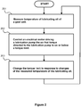
figure 2 shows a flow chart of a method according to an embodiment of the invention for controlling a lubrication pump of a gear unit. -
Figure 1 shows a schematic illustration of agear unit 100 according to an advantageous, exemplifying embodiment of the invention. The gear unit comprises afirst shaft 101 and asecond shaft 102 for connecting to an external mechanical system. The external mechanical system may comprise, for example but not necessarily, a wind turbine that can be connected to theshaft 101 and a generator that can be connected to theshaft 102, i.e. the gear unit can be for example a gear unit suitable for a wind power application. The gear unit comprises at least onegear stage 103 between theshafts lubrication pump 104 for circulating lubricating oil through the at least one gear stage andbearings 109 of the gear unit. The lubrication pump can be, for example, a gear type pump. In the exemplifying case shown infigure 1 , the gear unit comprises anoil tank 110 that constitutes a part of a circulation path of the lubricating oil. It is also possible that there is anoil sump 106 that constitutes, instead of or in addition to theoil tank 110, a reservoir for the lubricating oil. The gear unit comprises atemperature sensor 105 for measuring the temperature of the lubricating oil and supplying a temperature signal representative of the measured temperature. The temperature sensor is preferably arranged to measure the temperature of the lubricating oil from an inlet of thelubrication pump 104. However, it is also possible to measure the temperature from, for example, theoil tank 110. Furthermore, it is also possible to measure the temperature of the lubricating oil in an indirect way by measuring the temperature of the inlet tube of the lubrication pump or by measuring the temperature of the lubrication pump itself. The gear unit comprises anelectrical motor 107 for driving thelubrication pump 104, and anelectrical device 108 for energizing and controlling the electrical motor so that the torque directed to the lubrication pump is below a torque limit. Theelectrical device 108 is arranged to change the torque limit in response to changes of the temperature signal so that the torque limit is changed dynamically according to the measured temperature of the lubricating oil. The rotational speed of the lubrication pump depends on the torque-speed characteristics of the lubrication pump at the prevailing temperature and pressure of the lubricating oil being pumped. The rotational speed of thelubrication pump 104 is preferably limited to be below a speed limit. - In a gear unit according to an embodiment of the invention, the
electrical device 108 is arranged to increase the torque limit in response to an increase of the temperature of the lubricating oil when the temperature of the lubricating oil is below a point at which the lubrication ability of the lubricating oil is at its best, i.e. the increase of the lubrication ability due to the increase of the temperature is utilized by increasing the torque so as to shorten the cold start process. - In a gear unit according to an embodiment of the invention, the
electrical device 108 is arranged to change the speed limit in response to changes of the temperature signal. Hence, both the maximum allowable torque and the maximum allowable rotational speed can be changed dynamically according to the measured temperature of the lubricating oil. - In a gear unit according to another embodiment of the invention, the
electrical device 108 is arranged to increase the speed limit and decrease the torque limit in response to an increase of the temperature of the lubricating oil. Therefore, the upper limit of the mechanical power directed to the lubrication pump can be kept substantially constant when the lubricating oil is warmed up. The fact that there is an upper limit of the mechanical power can be utilized when dimensioning theelectrical motor 107 and theelectrical device 108. - In conjunction with gear units according to certain embodiments of the invention, the temperature range of the lubricating oil is divided into a plurality of successive sub-ranges. In a gear unit according to an embodiment of the invention, the
electrical device 108 is arranged to use a sub-range specific torque limit for each of the sub-ranges. In a gear unit according to an embodiment of the invention, theelectrical device 108 is arranged to use a sub-range specific torque limit and also a sub-range specific speed limit for each of the sub-ranges. The successive sub-ranges can be for example: under -10°C, -10°C...+10°C, +10°C...+40°C, over +40°C. - In a gear unit according to an embodiment of the invention, the
electrical device 108 is arranged to activate an oil-heater element 112 for warming up the lubricating oil when the measured temperature of the lubricating oil is below a first pre-determined temperature limit, e.g. +40°C. - In a gear unit according to an embodiment of the invention, the
electrical device 108 is arranged to activate the oil-heater element 112 for warming up the lubricating oil and also a pump-heater element 113 for warming up thelubrication pump 104 when the measured temperature of the lubricating oil is below a second pre-determined temperature limit, e.g. -10°C, that is lower than the first temperature limit. - In a gear unit according to an embodiment of the invention, the
electrical device 108 is arranged to activate ablower 115 of an oil-cooler element 114 for cooling the lubricating oil when the measured temperature of the lubricating oil is above a third pre-determined temperature limit, e.g. +50°C, that is higher than the first and second temperature limits. - In a gear unit according to an embodiment of the invention, the
electrical motor 107 is an alternating current motor and theelectrical device 108 comprises a frequency converter arranged to supply electrical energy to the electrical motor. The alternating current motor can be, for example, a three-phase induction motor. In the exemplifying case shown infigure 1 , theelectrical device 108 is supplied by a three-phaseelectrical power network 116. The frequency converter can be arranged to implement the limitation of the torque so that the amplitude or the effective value, e.g. the root mean square ("RMS"), of the current of the electrical motor is below a current limit and to implement the limitation of the rotational speed of the lubrication pump so that the frequency of the supply voltage of the electrical motor is below a frequency limit. A more accurate control of the torque can be achieved when the frequency converter is arranged to apply a vector control principle in which both the amplitudes and the instantaneous phases of the voltages and currents of the electrical motor are controlled instead of controlling only the amplitudes and the frequency. It is as well possible that theelectrical motor 107 is a direct current ("DC") motor in which case theelectrical device 108 may comprise e.g. a thyristor bridge for energizing and controlling the direct current motor. - A gear unit according to an embodiment of the invention comprises a
filter element 117 for removing impurities from the lubricating oil. - A gear unit according to an embodiment of the invention comprises a
sensor element 118 for monitoring the condition of the lubricating oil. The sensor element can be responsive, for example, to the purity degree of the lubricating oil and/or the water content of the lubricating oil. -
Figure 2 shows a flow chart of a method according to an embodiment of the invention for controlling a lubrication pump of a gear unit. The method comprises: - action 201: measuring temperature of lubricating oil circulated by the lubrication pump,
- action 202: controlling an electrical motor driving the lubrication pump so that the torque directed to the lubrication pump is below a torque limit, and
- action 203: changing the torque limit in response to changes of the measured temperature of the lubricating oil.
- A method according to an embodiment of the invention comprises increasing the torque limit in response to an increase of the temperature of the lubricating oil when the temperature of the lubricating oil is below a point at which the lubrication ability of the lubricating oil is at its best, i.e. the increase of the lubrication ability due to the increase of the temperature is utilized by increasing the torque so as to shorten the cold start process.
- A method according to an embodiment of the invention comprises controlling the electrical motor so that the torque directed to the lubrication pump is below the torque limit and the rotational speed of the lubrication pump is below a speed limit, and changing the torque limit and the speed limit in response to changes of the measured temperature of the lubricating oil.
- In a method according to an embodiment of the invention, the speed limit is increased and the torque limit is decreased in response to an increase of the temperature of the lubricating oil. Therefore, the upper limit of the mechanical power directed to the lubrication pump can be kept substantially constant when the lubricating oil is warmed up.
- In a method according to an embodiment of the invention, a range of the temperature of the lubricating oil is divided into a plurality of successive sub-ranges, and a sub-range specific torque limit is used for each of the sub-ranges.
- In a method according to an embodiment of the invention, the range of the temperature of the lubricating oil is divided into the plurality of the successive sub-ranges, and the sub-range specific torque limit and a sub-range specific speed limit are used for each of the sub-ranges.
- In a method according to an embodiment of the invention, the electrical motor is an alternating current motor and the torque is limited by limiting the amplitude or the effective value of the current of the electrical motor to be below a current limit, and the rotational speed of the lubrication pump is limited by limiting the frequency of the supply voltage of the electrical motor to be below a frequency limit.
- In a method according to an embodiment of the invention, the temperature of the lubricating oil is measured from an inlet of the lubrication pump.
- A computer program according to an embodiment of the invention comprises software modules for controlling a lubrication pump of a gear unit. The software modules comprise computer executable instructions for controlling a programmable processor to:
- deliver a torque limit to an electrical system driving the lubrication pump, the torque limit indicating the maximum allowable torque directed to the lubrication pump, and
- change the torque limit in response to changes of a signal representative of measured temperature of lubricating oil.
- The software modules can be, for example, subroutines and functions generated with a suitable programming language.
- A computer program product according to an embodiment of the invention comprises a computer readable medium, e.g. a compact disc ("CD"), encoded with a computer program according to an embodiment of the invention.
- A signal according to an embodiment of the invention is encoded to carry information defining a computer program according to an embodiment of the invention.
- The specific examples provided in the description given above should not be construed as limiting. Therefore, the invention is not limited merely to the embodiments described above.
Claims (15)
- A gear unit (100) comprising:- a first shaft (101) and a second shaft (102) for connecting to an external mechanical system,- at least one gear stage (103) between the first and second shafts,- a lubrication pump (104) for circulating lubricating oil through the at least one gear stage and bearings (109) of the gear unit,- a temperature sensor (105) for measuring temperature of the lubricating oil and supplying a temperature signal representative thereof,- an electrical motor (107) for driving the lubrication pump, and- an electrical device (108) for energizing and controlling the electrical motor so that torque directed to the lubrication pump is below a torque limit,
characterized in that the electrical device is arranged to change the torque limit in response to changes of the temperature signal. - A gear unit according to claim 1, wherein the electrical device is arranged to control the electrical motor so that rotational speed of the lubrication pump is below a speed limit, and to change the speed limit in response to changes of the temperature signal.
- A gear unit according to claim 2, wherein the electrical device is arranged to increase the speed limit and decrease the torque limit in response to an increase of the temperature of the lubricating oil.
- A gear unit according to any of claims 1-3, wherein a range of the temperature of the lubricating oil comprises a plurality of successive sub-ranges, and the electrical device is arranged to use a sub-range specific torque limit for each of the sub-ranges.
- A gear unit according to claims 4, wherein the successive sub-ranges are: under -10°C, -10°C...+10°C, +10°C...+40°C, over +40°C.
- A gear unit according to any of claims 1-5, wherein the electrical motor is an alternating current motor and the electrical device comprises a frequency converter arranged to supply electrical energy to the electrical motor.
- A gear unit according to claim 6, wherein the frequency converter is arranged to limit the torque so that an amplitude of current of the electrical motor is below a current limit and to limit the rotational speed of the lubrication pump so that a frequency of supply voltage of the electrical motor is below a frequency limit.
- A gear unit according to any of claims 1-7, wherein the temperature sensor (105) is arranged to measure the temperature of the lubricating oil from an inlet of the lubrication pump.
- A method for controlling a lubrication pump of a gear unit, the method comprising:- measuring (201) temperature of lubricating oil circulated by the lubrication pump, and- controlling (202) an electrical motor driving the lubrication pump so that torque directed to the lubrication pump is below a torque limit,
characterized in that the method comprises changing (203) the torque limit in response to changes of the measured temperature of the lubricating oil. - A method according to claim 9, wherein the method comprises controlling the electrical motor so that rotational speed of the lubrication pump is below a speed limit, and changing the speed limit in response to changes of the measured temperature.
- A method according to claim 10, wherein the speed limit is increased and the torque limit is decreased in response to an increase of the temperature of the lubricating oil.
- A method according to any of claims 9-11, wherein a range of the temperature of the lubricating oil is divided into a plurality of successive sub-ranges, and a sub-range specific torque limit is used for each of the sub-ranges.
- A method according to claim 9, wherein the electrical motor is an alternating current motor and the torque is limited by limiting an amplitude of current of the electrical motor to be below a current limit and rotational speed of the lubrication pump is limited by limiting a frequency of supply voltage of the electrical motor to be below a frequency limit.
- A method according to any of claims 9-13, wherein the temperature of the lubricating oil is measured from an inlet of the lubrication pump.
- A computer program for controlling a lubrication pump of a gear unit, the computer program comprising computer executable instructions for controlling a programmable processor to deliver a torque limit to an electrical system driving the lubrication pump, the torque limit indicating the maximum allowable torque directed to the lubrication pump, characterized in that the computer program further comprises computer executable instructions for controlling the programmable processor to change the torque limit in response to changes of a signal representative of measured temperature of lubricating oil.
Priority Applications (8)
| Application Number | Priority Date | Filing Date | Title |
|---|---|---|---|
| EP11182328.2A EP2573428B1 (en) | 2011-09-22 | 2011-09-22 | A gear unit and a method for controlling a lubrication pump of a gear unit |
| DK11182328.2T DK2573428T3 (en) | 2011-09-22 | 2011-09-22 | Gear unit and method for controlling a gear unit lubrication pump |
| ES11182328.2T ES2620265T3 (en) | 2011-09-22 | 2011-09-22 | Gear unit and method for controlling a lubrication pump of a gear unit |
| CA2790510A CA2790510C (en) | 2011-09-22 | 2012-09-20 | A gear unit and a method for controlling a lubrication pump of a gear unit |
| US13/624,595 US9618154B2 (en) | 2011-09-22 | 2012-09-21 | Gear unit and a method for controlling a lubrication pump of a gear unit |
| CN201210449153.5A CN103047399B (en) | 2011-09-22 | 2012-09-21 | Gear unit and the method being used for controlling the lubricating pump of gear unit |
| BR102012024124-2A BR102012024124B1 (en) | 2011-09-22 | 2012-09-24 | GEAR UNIT AND A METHOD FOR CONTROLLING A GEAR UNIT LUBRICATION PUMP |
| KR1020120106129A KR101890895B1 (en) | 2011-09-22 | 2012-09-24 | A gear unit and method for controlling a lubrication pump of a gear unit |
Applications Claiming Priority (1)
| Application Number | Priority Date | Filing Date | Title |
|---|---|---|---|
| EP11182328.2A EP2573428B1 (en) | 2011-09-22 | 2011-09-22 | A gear unit and a method for controlling a lubrication pump of a gear unit |
Publications (2)
| Publication Number | Publication Date |
|---|---|
| EP2573428A1 EP2573428A1 (en) | 2013-03-27 |
| EP2573428B1 true EP2573428B1 (en) | 2016-12-28 |
Family
ID=44759493
Family Applications (1)
| Application Number | Title | Priority Date | Filing Date |
|---|---|---|---|
| EP11182328.2A Active EP2573428B1 (en) | 2011-09-22 | 2011-09-22 | A gear unit and a method for controlling a lubrication pump of a gear unit |
Country Status (8)
| Country | Link |
|---|---|
| US (1) | US9618154B2 (en) |
| EP (1) | EP2573428B1 (en) |
| KR (1) | KR101890895B1 (en) |
| CN (1) | CN103047399B (en) |
| BR (1) | BR102012024124B1 (en) |
| CA (1) | CA2790510C (en) |
| DK (1) | DK2573428T3 (en) |
| ES (1) | ES2620265T3 (en) |
Families Citing this family (19)
| Publication number | Priority date | Publication date | Assignee | Title |
|---|---|---|---|---|
| US20130288843A1 (en) * | 2010-10-15 | 2013-10-31 | Vestas Wind Systems A/S | Machine system having a lubrication system |
| DK2573429T3 (en) * | 2011-09-22 | 2014-07-21 | Moventas Gears Oy | Method for controlling the lubrication of a drive unit and a drive unit |
| EP2573388B1 (en) * | 2011-09-22 | 2018-11-07 | Moventas Gears Oy | A method for controlling lubrication of a gear unit and a gear unit |
| US8869940B2 (en) * | 2012-01-17 | 2014-10-28 | General Electric Company | Dual temperature oil control system and method for a wind turbine gearbox |
| DE102013203263A1 (en) | 2013-02-27 | 2014-08-28 | Skf Lubrication Systems Germany Ag | Device for supplying lubricant to a lubrication point in a machine |
| CN103307434A (en) * | 2013-06-09 | 2013-09-18 | 安徽永杰铜业有限公司 | Pressure regulation device for copper strip rolling mill gearbox lubrication system |
| CN103604032B (en) * | 2013-10-21 | 2019-10-25 | 启东中冶润滑液压设备有限公司 | Nylon gear lubricating arrangement |
| CN103498913B (en) * | 2013-10-23 | 2015-12-09 | 大连华锐重工集团股份有限公司 | Be applicable to the wind turbine gearbox lubrication system of extreme operating condition |
| ES2645649T3 (en) * | 2014-05-20 | 2017-12-07 | Moventas Gears Oy | A gear unit and a method for heating lubricating oil of a gear unit |
| GB201409180D0 (en) * | 2014-05-23 | 2014-07-09 | Qinetiq Ltd | Improvements to oil pumps for motor vehicles |
| CN104197180A (en) * | 2014-08-05 | 2014-12-10 | 蔡宏磊 | Temperature control device for lubricating oil return |
| CN104601050B (en) * | 2014-12-24 | 2017-10-31 | 大连尚能科技发展有限公司 | A kind of speed regulating method of Oil pump electrical machinery |
| CN110553027A (en) * | 2018-06-01 | 2019-12-10 | 中国船舶重工集团海装风电股份有限公司 | Gear box cooling and lubricating system and wind generating set with same |
| FR3093139B1 (en) * | 2019-02-21 | 2021-01-22 | Renault Sas | PROCESS FOR CHECKING THE START OF AN OIL PUMP |
| CN110333674A (en) * | 2019-06-22 | 2019-10-15 | 郑州盛川科技有限公司 | A kind of lubricating system Closed loop Control and embodiment |
| DE102019214650B3 (en) * | 2019-09-25 | 2020-12-10 | Hanon Systems Efp Deutschland Gmbh | Control unit for pressure regulation |
| CN113250918A (en) * | 2021-06-07 | 2021-08-13 | 天津瑞能电气有限公司 | Maintenance device is maintained to wind generating set gear box |
| CN113404779B (en) * | 2021-08-18 | 2021-11-23 | 河南卫华重型机械股份有限公司 | Full-automatic monitoring control centralized lubricating system for crane traveling wheels |
| CN115789233B (en) * | 2023-02-08 | 2023-05-02 | 南京讯联液压技术股份有限公司 | Lubrication servo control system of wind power generation gear box |
Family Cites Families (23)
| Publication number | Priority date | Publication date | Assignee | Title |
|---|---|---|---|---|
| JPS58157385A (en) * | 1982-03-12 | 1983-09-19 | Fanuc Ltd | Drive system for ac motor |
| US5310020A (en) * | 1993-06-09 | 1994-05-10 | Ingersoll-Rand Company | Self contained lubricating oil system for a centrifugal compressor |
| JP3329417B2 (en) * | 1994-09-21 | 2002-09-30 | 株式会社フジユニバンス | Lubrication structure of transfer device |
| JPH08251868A (en) * | 1995-03-06 | 1996-09-27 | Komatsu Ltd | Electrohydraulic hybrid motor |
| JP3168951B2 (en) * | 1997-09-01 | 2001-05-21 | 日産自動車株式会社 | Transmission control device for continuously variable transmission |
| JP3383754B2 (en) * | 1997-09-29 | 2003-03-04 | 日立建機株式会社 | Hydraulic construction machine hydraulic pump torque control device |
| DE10316515B4 (en) * | 2003-04-09 | 2005-04-28 | Prec Drilling Tech Serv Group | Method and device for generating signals that can be transmitted in a borehole |
| FI20040351A (en) * | 2004-03-04 | 2005-09-05 | Abb Oy | Measurement method and device |
| JP3997227B2 (en) * | 2004-12-02 | 2007-10-24 | 本田技研工業株式会社 | Hydraulic supply device |
| JP4614811B2 (en) * | 2005-04-04 | 2011-01-19 | トヨタ自動車株式会社 | Drive device, automobile equipped with the same, and drive device control method |
| JP4380636B2 (en) * | 2006-01-24 | 2009-12-09 | トヨタ自動車株式会社 | Oil pump control device for electric vehicle and electric vehicle equipped with the same |
| US7508149B2 (en) * | 2007-06-07 | 2009-03-24 | Gm Global Technology Operations, Inc. | Oil pump systems and methods for preventing torque overload in motors of oil pump systems |
| WO2009037996A1 (en) * | 2007-09-21 | 2009-03-26 | Toyota Jidosha Kabushiki Kaisha | Control device for vehicular hydraulic control circuit |
| US8790089B2 (en) * | 2008-06-29 | 2014-07-29 | Bristol Compressors International, Inc. | Compressor speed control system for bearing reliability |
| KR101173050B1 (en) * | 2009-12-04 | 2012-08-13 | 기아자동차주식회사 | Drive control apparatus and method for electric oil pump |
| CN201575285U (en) | 2009-12-10 | 2010-09-08 | 天津钢管集团股份有限公司 | Thin oil lubricating system for large-sized speed reducer |
| JP5285707B2 (en) * | 2010-02-19 | 2013-09-11 | 三菱重工業株式会社 | Method for starting rotating machine and method for starting wind power generator |
| JP5416060B2 (en) * | 2010-09-06 | 2014-02-12 | 日立オートモティブシステムズ株式会社 | Control device for electric oil pump for vehicle |
| JP5134663B2 (en) * | 2010-09-10 | 2013-01-30 | ジヤトコ株式会社 | Transmission oil supply device |
| JP5193259B2 (en) * | 2010-09-14 | 2013-05-08 | 株式会社日立カーエンジニアリング | Motor control device and control method for electric oil pump |
| CN201810502U (en) * | 2010-10-22 | 2011-04-27 | 大连华锐股份有限公司 | Gear box lubricating system for wind generating set |
| US8936135B2 (en) * | 2010-11-29 | 2015-01-20 | Lincoln Industrial Corporation | Pump having heated reservoir |
| JP2012207637A (en) * | 2011-03-30 | 2012-10-25 | Hitachi Automotive Systems Ltd | Electric oil pump |
-
2011
- 2011-09-22 DK DK11182328.2T patent/DK2573428T3/en active
- 2011-09-22 EP EP11182328.2A patent/EP2573428B1/en active Active
- 2011-09-22 ES ES11182328.2T patent/ES2620265T3/en active Active
-
2012
- 2012-09-20 CA CA2790510A patent/CA2790510C/en active Active
- 2012-09-21 US US13/624,595 patent/US9618154B2/en active Active
- 2012-09-21 CN CN201210449153.5A patent/CN103047399B/en active Active
- 2012-09-24 KR KR1020120106129A patent/KR101890895B1/en active IP Right Grant
- 2012-09-24 BR BR102012024124-2A patent/BR102012024124B1/en active IP Right Grant
Non-Patent Citations (1)
| Title |
|---|
| None * |
Also Published As
| Publication number | Publication date |
|---|---|
| CA2790510A1 (en) | 2013-03-22 |
| CN103047399B (en) | 2016-08-24 |
| BR102012024124A8 (en) | 2016-04-05 |
| US9618154B2 (en) | 2017-04-11 |
| KR20130032289A (en) | 2013-04-01 |
| DK2573428T3 (en) | 2017-04-03 |
| BR102012024124A2 (en) | 2014-12-09 |
| BR102012024124B1 (en) | 2022-03-08 |
| CN103047399A (en) | 2013-04-17 |
| ES2620265T3 (en) | 2017-06-28 |
| KR101890895B1 (en) | 2018-08-22 |
| CA2790510C (en) | 2019-10-29 |
| EP2573428A1 (en) | 2013-03-27 |
| US20130075198A1 (en) | 2013-03-28 |
Similar Documents
| Publication | Publication Date | Title |
|---|---|---|
| EP2573428B1 (en) | A gear unit and a method for controlling a lubrication pump of a gear unit | |
| EP2573388B1 (en) | A method for controlling lubrication of a gear unit and a gear unit | |
| JP5285707B2 (en) | Method for starting rotating machine and method for starting wind power generator | |
| JP5680415B2 (en) | Integrated fan drive system for cooling tower | |
| DK2573391T3 (en) | Method and arrangement for controlling the lubrication of an exchange | |
| EP2184487A1 (en) | Wind turbine lubrication system | |
| WO2015041805A1 (en) | System and method for converterless operation of motors-driven pumps | |
| WO2009003478A2 (en) | Thermal monitoring of doubly-fed generator | |
| JPWO2010001479A1 (en) | Wind power generator | |
| US10309518B2 (en) | Gear unit and a method for heating lubricant oil of a gear unit | |
| EP2652322B1 (en) | A wind turbine and a method of operating a wind turbine | |
| SE0950602A1 (en) | Wind turbine control system | |
| US20210310488A1 (en) | Vacuum Pump | |
| KR101133253B1 (en) | A Forced Circulation Device of lubrication Oil for Windmill | |
| CN105089934B (en) | method for operating a wind turbine | |
| Rajora et al. | Effect of lube oil temperature on turbine shaft vibration | |
| JP5643694B2 (en) | Spindle control device and spindle control method | |
| KR101265435B1 (en) | Starting method for rotation machine and starting method for wind turbine generator | |
| US20230243467A1 (en) | Method for starting an aircraft engine | |
| JP2020020432A (en) | Grease supply device and wind power generation system using the same | |
| EP2889516A1 (en) | A hydraulic transmission, an operation method thereof and a power generating apparatus of a renewable energy type | |
| JP2017155665A (en) | Turbine turning device |
Legal Events
| Date | Code | Title | Description |
|---|---|---|---|
| PUAI | Public reference made under article 153(3) epc to a published international application that has entered the european phase |
Free format text: ORIGINAL CODE: 0009012 |
|
| AK | Designated contracting states |
Kind code of ref document: A1 Designated state(s): AL AT BE BG CH CY CZ DE DK EE ES FI FR GB GR HR HU IE IS IT LI LT LU LV MC MK MT NL NO PL PT RO RS SE SI SK SM TR |
|
| AX | Request for extension of the european patent |
Extension state: BA ME |
|
| 17P | Request for examination filed |
Effective date: 20130903 |
|
| RBV | Designated contracting states (corrected) |
Designated state(s): AL AT BE BG CH CY CZ DE DK EE ES FI FR GB GR HR HU IE IS IT LI LT LU LV MC MK MT NL NO PL PT RO RS SE SI SK SM TR |
|
| REG | Reference to a national code |
Ref country code: HK Ref legal event code: DE Ref document number: 1182754 Country of ref document: HK |
|
| 17Q | First examination report despatched |
Effective date: 20150113 |
|
| RIC1 | Information provided on ipc code assigned before grant |
Ipc: F16N 7/38 20060101ALI20160616BHEP Ipc: F16H 57/04 20060101AFI20160616BHEP Ipc: F16N 39/04 20060101ALI20160616BHEP |
|
| GRAP | Despatch of communication of intention to grant a patent |
Free format text: ORIGINAL CODE: EPIDOSNIGR1 |
|
| INTG | Intention to grant announced |
Effective date: 20160804 |
|
| GRAS | Grant fee paid |
Free format text: ORIGINAL CODE: EPIDOSNIGR3 |
|
| GRAA | (expected) grant |
Free format text: ORIGINAL CODE: 0009210 |
|
| AK | Designated contracting states |
Kind code of ref document: B1 Designated state(s): AL AT BE BG CH CY CZ DE DK EE ES FI FR GB GR HR HU IE IS IT LI LT LU LV MC MK MT NL NO PL PT RO RS SE SI SK SM TR |
|
| REG | Reference to a national code |
Ref country code: GB Ref legal event code: FG4D |
|
| REG | Reference to a national code |
Ref country code: CH Ref legal event code: EP |
|
| REG | Reference to a national code |
Ref country code: AT Ref legal event code: REF Ref document number: 857596 Country of ref document: AT Kind code of ref document: T Effective date: 20170115 |
|
| REG | Reference to a national code |
Ref country code: IE Ref legal event code: FG4D |
|
| REG | Reference to a national code |
Ref country code: DE Ref legal event code: R096 Ref document number: 602011033787 Country of ref document: DE |
|
| PG25 | Lapsed in a contracting state [announced via postgrant information from national office to epo] |
Ref country code: LV Free format text: LAPSE BECAUSE OF FAILURE TO SUBMIT A TRANSLATION OF THE DESCRIPTION OR TO PAY THE FEE WITHIN THE PRESCRIBED TIME-LIMIT Effective date: 20161228 |
|
| REG | Reference to a national code |
Ref country code: DK Ref legal event code: T3 Effective date: 20170328 |
|
| REG | Reference to a national code |
Ref country code: LT Ref legal event code: MG4D |
|
| PG25 | Lapsed in a contracting state [announced via postgrant information from national office to epo] |
Ref country code: NO Free format text: LAPSE BECAUSE OF FAILURE TO SUBMIT A TRANSLATION OF THE DESCRIPTION OR TO PAY THE FEE WITHIN THE PRESCRIBED TIME-LIMIT Effective date: 20170328 Ref country code: LT Free format text: LAPSE BECAUSE OF FAILURE TO SUBMIT A TRANSLATION OF THE DESCRIPTION OR TO PAY THE FEE WITHIN THE PRESCRIBED TIME-LIMIT Effective date: 20161228 Ref country code: SE Free format text: LAPSE BECAUSE OF FAILURE TO SUBMIT A TRANSLATION OF THE DESCRIPTION OR TO PAY THE FEE WITHIN THE PRESCRIBED TIME-LIMIT Effective date: 20161228 Ref country code: GR Free format text: LAPSE BECAUSE OF FAILURE TO SUBMIT A TRANSLATION OF THE DESCRIPTION OR TO PAY THE FEE WITHIN THE PRESCRIBED TIME-LIMIT Effective date: 20170329 |
|
| REG | Reference to a national code |
Ref country code: NL Ref legal event code: MP Effective date: 20161228 |
|
| REG | Reference to a national code |
Ref country code: AT Ref legal event code: MK05 Ref document number: 857596 Country of ref document: AT Kind code of ref document: T Effective date: 20161228 |
|
| PG25 | Lapsed in a contracting state [announced via postgrant information from national office to epo] |
Ref country code: HR Free format text: LAPSE BECAUSE OF FAILURE TO SUBMIT A TRANSLATION OF THE DESCRIPTION OR TO PAY THE FEE WITHIN THE PRESCRIBED TIME-LIMIT Effective date: 20161228 Ref country code: RS Free format text: LAPSE BECAUSE OF FAILURE TO SUBMIT A TRANSLATION OF THE DESCRIPTION OR TO PAY THE FEE WITHIN THE PRESCRIBED TIME-LIMIT Effective date: 20161228 |
|
| REG | Reference to a national code |
Ref country code: ES Ref legal event code: FG2A Ref document number: 2620265 Country of ref document: ES Kind code of ref document: T3 Effective date: 20170628 |
|
| PG25 | Lapsed in a contracting state [announced via postgrant information from national office to epo] |
Ref country code: NL Free format text: LAPSE BECAUSE OF FAILURE TO SUBMIT A TRANSLATION OF THE DESCRIPTION OR TO PAY THE FEE WITHIN THE PRESCRIBED TIME-LIMIT Effective date: 20161228 |
|
| PG25 | Lapsed in a contracting state [announced via postgrant information from national office to epo] |
Ref country code: SK Free format text: LAPSE BECAUSE OF FAILURE TO SUBMIT A TRANSLATION OF THE DESCRIPTION OR TO PAY THE FEE WITHIN THE PRESCRIBED TIME-LIMIT Effective date: 20161228 Ref country code: RO Free format text: LAPSE BECAUSE OF FAILURE TO SUBMIT A TRANSLATION OF THE DESCRIPTION OR TO PAY THE FEE WITHIN THE PRESCRIBED TIME-LIMIT Effective date: 20161228 Ref country code: EE Free format text: LAPSE BECAUSE OF FAILURE TO SUBMIT A TRANSLATION OF THE DESCRIPTION OR TO PAY THE FEE WITHIN THE PRESCRIBED TIME-LIMIT Effective date: 20161228 Ref country code: IS Free format text: LAPSE BECAUSE OF FAILURE TO SUBMIT A TRANSLATION OF THE DESCRIPTION OR TO PAY THE FEE WITHIN THE PRESCRIBED TIME-LIMIT Effective date: 20170428 |
|
| PG25 | Lapsed in a contracting state [announced via postgrant information from national office to epo] |
Ref country code: PT Free format text: LAPSE BECAUSE OF FAILURE TO SUBMIT A TRANSLATION OF THE DESCRIPTION OR TO PAY THE FEE WITHIN THE PRESCRIBED TIME-LIMIT Effective date: 20170428 Ref country code: SM Free format text: LAPSE BECAUSE OF FAILURE TO SUBMIT A TRANSLATION OF THE DESCRIPTION OR TO PAY THE FEE WITHIN THE PRESCRIBED TIME-LIMIT Effective date: 20161228 Ref country code: PL Free format text: LAPSE BECAUSE OF FAILURE TO SUBMIT A TRANSLATION OF THE DESCRIPTION OR TO PAY THE FEE WITHIN THE PRESCRIBED TIME-LIMIT Effective date: 20161228 Ref country code: AT Free format text: LAPSE BECAUSE OF FAILURE TO SUBMIT A TRANSLATION OF THE DESCRIPTION OR TO PAY THE FEE WITHIN THE PRESCRIBED TIME-LIMIT Effective date: 20161228 Ref country code: BG Free format text: LAPSE BECAUSE OF FAILURE TO SUBMIT A TRANSLATION OF THE DESCRIPTION OR TO PAY THE FEE WITHIN THE PRESCRIBED TIME-LIMIT Effective date: 20170328 |
|
| REG | Reference to a national code |
Ref country code: FR Ref legal event code: PLFP Year of fee payment: 7 |
|
| REG | Reference to a national code |
Ref country code: DE Ref legal event code: R097 Ref document number: 602011033787 Country of ref document: DE |
|
| REG | Reference to a national code |
Ref country code: HK Ref legal event code: GR Ref document number: 1182754 Country of ref document: HK |
|
| PLBE | No opposition filed within time limit |
Free format text: ORIGINAL CODE: 0009261 |
|
| STAA | Information on the status of an ep patent application or granted ep patent |
Free format text: STATUS: NO OPPOSITION FILED WITHIN TIME LIMIT |
|
| 26N | No opposition filed |
Effective date: 20170929 |
|
| PG25 | Lapsed in a contracting state [announced via postgrant information from national office to epo] |
Ref country code: SI Free format text: LAPSE BECAUSE OF FAILURE TO SUBMIT A TRANSLATION OF THE DESCRIPTION OR TO PAY THE FEE WITHIN THE PRESCRIBED TIME-LIMIT Effective date: 20161228 |
|
| REG | Reference to a national code |
Ref country code: CH Ref legal event code: PL |
|
| PG25 | Lapsed in a contracting state [announced via postgrant information from national office to epo] |
Ref country code: MC Free format text: LAPSE BECAUSE OF FAILURE TO SUBMIT A TRANSLATION OF THE DESCRIPTION OR TO PAY THE FEE WITHIN THE PRESCRIBED TIME-LIMIT Effective date: 20161228 |
|
| REG | Reference to a national code |
Ref country code: IE Ref legal event code: MM4A |
|
| PG25 | Lapsed in a contracting state [announced via postgrant information from national office to epo] |
Ref country code: LU Free format text: LAPSE BECAUSE OF NON-PAYMENT OF DUE FEES Effective date: 20170922 |
|
| PG25 | Lapsed in a contracting state [announced via postgrant information from national office to epo] |
Ref country code: LI Free format text: LAPSE BECAUSE OF NON-PAYMENT OF DUE FEES Effective date: 20170930 Ref country code: CH Free format text: LAPSE BECAUSE OF NON-PAYMENT OF DUE FEES Effective date: 20170930 Ref country code: IE Free format text: LAPSE BECAUSE OF NON-PAYMENT OF DUE FEES Effective date: 20170922 |
|
| PG25 | Lapsed in a contracting state [announced via postgrant information from national office to epo] |
Ref country code: IT Free format text: LAPSE BECAUSE OF NON-PAYMENT OF DUE FEES Effective date: 20170922 |
|
| REG | Reference to a national code |
Ref country code: FR Ref legal event code: PLFP Year of fee payment: 8 |
|
| PG25 | Lapsed in a contracting state [announced via postgrant information from national office to epo] |
Ref country code: MT Free format text: LAPSE BECAUSE OF NON-PAYMENT OF DUE FEES Effective date: 20170922 |
|
| PG25 | Lapsed in a contracting state [announced via postgrant information from national office to epo] |
Ref country code: HU Free format text: LAPSE BECAUSE OF FAILURE TO SUBMIT A TRANSLATION OF THE DESCRIPTION OR TO PAY THE FEE WITHIN THE PRESCRIBED TIME-LIMIT; INVALID AB INITIO Effective date: 20110922 |
|
| PG25 | Lapsed in a contracting state [announced via postgrant information from national office to epo] |
Ref country code: CY Free format text: LAPSE BECAUSE OF NON-PAYMENT OF DUE FEES Effective date: 20161228 |
|
| PG25 | Lapsed in a contracting state [announced via postgrant information from national office to epo] |
Ref country code: MK Free format text: LAPSE BECAUSE OF FAILURE TO SUBMIT A TRANSLATION OF THE DESCRIPTION OR TO PAY THE FEE WITHIN THE PRESCRIBED TIME-LIMIT Effective date: 20161228 |
|
| PG25 | Lapsed in a contracting state [announced via postgrant information from national office to epo] |
Ref country code: TR Free format text: LAPSE BECAUSE OF FAILURE TO SUBMIT A TRANSLATION OF THE DESCRIPTION OR TO PAY THE FEE WITHIN THE PRESCRIBED TIME-LIMIT Effective date: 20161228 |
|
| PG25 | Lapsed in a contracting state [announced via postgrant information from national office to epo] |
Ref country code: AL Free format text: LAPSE BECAUSE OF FAILURE TO SUBMIT A TRANSLATION OF THE DESCRIPTION OR TO PAY THE FEE WITHIN THE PRESCRIBED TIME-LIMIT Effective date: 20161228 |
|
| PGFP | Annual fee paid to national office [announced via postgrant information from national office to epo] |
Ref country code: GB Payment date: 20220920 Year of fee payment: 12 Ref country code: DK Payment date: 20220922 Year of fee payment: 12 Ref country code: CZ Payment date: 20220915 Year of fee payment: 12 |
|
| PGFP | Annual fee paid to national office [announced via postgrant information from national office to epo] |
Ref country code: FR Payment date: 20220922 Year of fee payment: 12 |
|
| PGFP | Annual fee paid to national office [announced via postgrant information from national office to epo] |
Ref country code: FI Payment date: 20230920 Year of fee payment: 13 |
|
| PGFP | Annual fee paid to national office [announced via postgrant information from national office to epo] |
Ref country code: DE Payment date: 20230920 Year of fee payment: 13 Ref country code: BE Payment date: 20230920 Year of fee payment: 13 |
|
| PGFP | Annual fee paid to national office [announced via postgrant information from national office to epo] |
Ref country code: ES Payment date: 20231124 Year of fee payment: 13 |