EP2573406A1 - Pressure control valve - Google Patents
Pressure control valve Download PDFInfo
- Publication number
- EP2573406A1 EP2573406A1 EP10851800A EP10851800A EP2573406A1 EP 2573406 A1 EP2573406 A1 EP 2573406A1 EP 10851800 A EP10851800 A EP 10851800A EP 10851800 A EP10851800 A EP 10851800A EP 2573406 A1 EP2573406 A1 EP 2573406A1
- Authority
- EP
- European Patent Office
- Prior art keywords
- pressure
- poppet
- valve seat
- path
- pilot poppet
- Prior art date
- Legal status (The legal status is an assumption and is not a legal conclusion. Google has not performed a legal analysis and makes no representation as to the accuracy of the status listed.)
- Withdrawn
Links
Images



Classifications
-
- F—MECHANICAL ENGINEERING; LIGHTING; HEATING; WEAPONS; BLASTING
- F15—FLUID-PRESSURE ACTUATORS; HYDRAULICS OR PNEUMATICS IN GENERAL
- F15B—SYSTEMS ACTING BY MEANS OF FLUIDS IN GENERAL; FLUID-PRESSURE ACTUATORS, e.g. SERVOMOTORS; DETAILS OF FLUID-PRESSURE SYSTEMS, NOT OTHERWISE PROVIDED FOR
- F15B13/00—Details of servomotor systems ; Valves for servomotor systems
- F15B13/02—Fluid distribution or supply devices characterised by their adaptation to the control of servomotors
- F15B13/04—Fluid distribution or supply devices characterised by their adaptation to the control of servomotors for use with a single servomotor
- F15B13/042—Fluid distribution or supply devices characterised by their adaptation to the control of servomotors for use with a single servomotor operated by fluid pressure
- F15B13/0426—Fluid distribution or supply devices characterised by their adaptation to the control of servomotors for use with a single servomotor operated by fluid pressure with fluid-operated pilot valves, i.e. multiple stage valves
-
- E—FIXED CONSTRUCTIONS
- E02—HYDRAULIC ENGINEERING; FOUNDATIONS; SOIL SHIFTING
- E02F—DREDGING; SOIL-SHIFTING
- E02F9/00—Component parts of dredgers or soil-shifting machines, not restricted to one of the kinds covered by groups E02F3/00 - E02F7/00
- E02F9/20—Drives; Control devices
- E02F9/22—Hydraulic or pneumatic drives
- E02F9/226—Safety arrangements, e.g. hydraulic driven fans, preventing cavitation, leakage, overheating
-
- F—MECHANICAL ENGINEERING; LIGHTING; HEATING; WEAPONS; BLASTING
- F15—FLUID-PRESSURE ACTUATORS; HYDRAULICS OR PNEUMATICS IN GENERAL
- F15B—SYSTEMS ACTING BY MEANS OF FLUIDS IN GENERAL; FLUID-PRESSURE ACTUATORS, e.g. SERVOMOTORS; DETAILS OF FLUID-PRESSURE SYSTEMS, NOT OTHERWISE PROVIDED FOR
- F15B11/00—Servomotor systems without provision for follow-up action; Circuits therefor
- F15B11/02—Systems essentially incorporating special features for controlling the speed or actuating force of an output member
- F15B11/04—Systems essentially incorporating special features for controlling the speed or actuating force of an output member for controlling the speed
- F15B11/044—Systems essentially incorporating special features for controlling the speed or actuating force of an output member for controlling the speed by means in the return line, i.e. "meter out"
- F15B11/0445—Systems essentially incorporating special features for controlling the speed or actuating force of an output member for controlling the speed by means in the return line, i.e. "meter out" with counterbalance valves, e.g. to prevent overrunning or for braking
-
- F—MECHANICAL ENGINEERING; LIGHTING; HEATING; WEAPONS; BLASTING
- F15—FLUID-PRESSURE ACTUATORS; HYDRAULICS OR PNEUMATICS IN GENERAL
- F15B—SYSTEMS ACTING BY MEANS OF FLUIDS IN GENERAL; FLUID-PRESSURE ACTUATORS, e.g. SERVOMOTORS; DETAILS OF FLUID-PRESSURE SYSTEMS, NOT OTHERWISE PROVIDED FOR
- F15B13/00—Details of servomotor systems ; Valves for servomotor systems
- F15B13/02—Fluid distribution or supply devices characterised by their adaptation to the control of servomotors
- F15B13/024—Pressure relief valves
-
- F—MECHANICAL ENGINEERING; LIGHTING; HEATING; WEAPONS; BLASTING
- F15—FLUID-PRESSURE ACTUATORS; HYDRAULICS OR PNEUMATICS IN GENERAL
- F15B—SYSTEMS ACTING BY MEANS OF FLUIDS IN GENERAL; FLUID-PRESSURE ACTUATORS, e.g. SERVOMOTORS; DETAILS OF FLUID-PRESSURE SYSTEMS, NOT OTHERWISE PROVIDED FOR
- F15B20/00—Safety arrangements for fluid actuator systems; Applications of safety devices in fluid actuator systems; Emergency measures for fluid actuator systems
- F15B20/005—Leakage; Spillage; Hose burst
-
- F—MECHANICAL ENGINEERING; LIGHTING; HEATING; WEAPONS; BLASTING
- F16—ENGINEERING ELEMENTS AND UNITS; GENERAL MEASURES FOR PRODUCING AND MAINTAINING EFFECTIVE FUNCTIONING OF MACHINES OR INSTALLATIONS; THERMAL INSULATION IN GENERAL
- F16K—VALVES; TAPS; COCKS; ACTUATING-FLOATS; DEVICES FOR VENTING OR AERATING
- F16K1/00—Lift valves or globe valves, i.e. cut-off apparatus with closure members having at least a component of their opening and closing motion perpendicular to the closing faces
- F16K1/32—Details
- F16K1/34—Cutting-off parts, e.g. valve members, seats
- F16K1/42—Valve seats
- F16K1/422—Valve seats attachable by a threaded connection to the housing
-
- F—MECHANICAL ENGINEERING; LIGHTING; HEATING; WEAPONS; BLASTING
- F16—ENGINEERING ELEMENTS AND UNITS; GENERAL MEASURES FOR PRODUCING AND MAINTAINING EFFECTIVE FUNCTIONING OF MACHINES OR INSTALLATIONS; THERMAL INSULATION IN GENERAL
- F16K—VALVES; TAPS; COCKS; ACTUATING-FLOATS; DEVICES FOR VENTING OR AERATING
- F16K17/00—Safety valves; Equalising valves, e.g. pressure relief valves
- F16K17/02—Safety valves; Equalising valves, e.g. pressure relief valves opening on surplus pressure on one side; closing on insufficient pressure on one side
- F16K17/04—Safety valves; Equalising valves, e.g. pressure relief valves opening on surplus pressure on one side; closing on insufficient pressure on one side spring-loaded
- F16K17/10—Safety valves; Equalising valves, e.g. pressure relief valves opening on surplus pressure on one side; closing on insufficient pressure on one side spring-loaded with auxiliary valve for fluid operation of the main valve
- F16K17/105—Safety valves; Equalising valves, e.g. pressure relief valves opening on surplus pressure on one side; closing on insufficient pressure on one side spring-loaded with auxiliary valve for fluid operation of the main valve using choking or throttling means to control the fluid operation of the main valve
-
- F—MECHANICAL ENGINEERING; LIGHTING; HEATING; WEAPONS; BLASTING
- F16—ENGINEERING ELEMENTS AND UNITS; GENERAL MEASURES FOR PRODUCING AND MAINTAINING EFFECTIVE FUNCTIONING OF MACHINES OR INSTALLATIONS; THERMAL INSULATION IN GENERAL
- F16K—VALVES; TAPS; COCKS; ACTUATING-FLOATS; DEVICES FOR VENTING OR AERATING
- F16K17/00—Safety valves; Equalising valves, e.g. pressure relief valves
- F16K17/18—Safety valves; Equalising valves, e.g. pressure relief valves opening on surplus pressure on either side
- F16K17/19—Equalising valves predominantly for tanks
- F16K17/196—Equalising valves predominantly for tanks spring-loaded
-
- F—MECHANICAL ENGINEERING; LIGHTING; HEATING; WEAPONS; BLASTING
- F16—ENGINEERING ELEMENTS AND UNITS; GENERAL MEASURES FOR PRODUCING AND MAINTAINING EFFECTIVE FUNCTIONING OF MACHINES OR INSTALLATIONS; THERMAL INSULATION IN GENERAL
- F16K—VALVES; TAPS; COCKS; ACTUATING-FLOATS; DEVICES FOR VENTING OR AERATING
- F16K47/00—Means in valves for absorbing fluid energy
- F16K47/04—Means in valves for absorbing fluid energy for decreasing pressure or noise level, the throttle being incorporated in the closure member
-
- Y—GENERAL TAGGING OF NEW TECHNOLOGICAL DEVELOPMENTS; GENERAL TAGGING OF CROSS-SECTIONAL TECHNOLOGIES SPANNING OVER SEVERAL SECTIONS OF THE IPC; TECHNICAL SUBJECTS COVERED BY FORMER USPC CROSS-REFERENCE ART COLLECTIONS [XRACs] AND DIGESTS
- Y10—TECHNICAL SUBJECTS COVERED BY FORMER USPC
- Y10T—TECHNICAL SUBJECTS COVERED BY FORMER US CLASSIFICATION
- Y10T137/00—Fluid handling
- Y10T137/7722—Line condition change responsive valves
- Y10T137/7758—Pilot or servo controlled
- Y10T137/7762—Fluid pressure type
- Y10T137/7764—Choked or throttled pressure type
- Y10T137/7768—Pilot controls supply to pressure chamber
-
- Y—GENERAL TAGGING OF NEW TECHNOLOGICAL DEVELOPMENTS; GENERAL TAGGING OF CROSS-SECTIONAL TECHNOLOGIES SPANNING OVER SEVERAL SECTIONS OF THE IPC; TECHNICAL SUBJECTS COVERED BY FORMER USPC CROSS-REFERENCE ART COLLECTIONS [XRACs] AND DIGESTS
- Y10—TECHNICAL SUBJECTS COVERED BY FORMER USPC
- Y10T—TECHNICAL SUBJECTS COVERED BY FORMER US CLASSIFICATION
- Y10T137/00—Fluid handling
- Y10T137/7722—Line condition change responsive valves
- Y10T137/7837—Direct response valves [i.e., check valve type]
- Y10T137/7838—Plural
Definitions
- the present invention relates to a pressure control valve for a construction machine. More particularly, the present invention relates to a pilot poppet type pressure control valve, which can protect a hydraulic system by being shifted to feed a high-pressure flow rate on a hydraulic pump side back to a hydraulic tank side when hydraulic pressure on the hydraulic pump side is increased in excess of a predetermined pressure.
- a pressure control valve in the related art includes a sleeve 3 having an inlet port 1 receiving an inflow of high-pressure hydraulic fluid from a hydraulic pump P and a low-pressure path 2 communicating with a hydraulic tank T, a main poppet 4 detachably mounted (seated/unseated) on the sleeve 3 to open and close the low-pressure path 2 with respect to the inlet port 11, a piston 6 slidably coupled to the main poppet 4 to be elastically supported by a piston spring 5, a main poppet spring 7 elastically biasing the main poppet 4 in an initial state by pressing the main poppet 4 to maintain the low-pressure path 2 closed with respect to the inlet port 1, a valve seat 9 installed in the sleeve 3 to face the main poppet 4 so as to form a pressure chamber 8, a pilot poppet 10 seated on or unseated from the valve sheet 9 to open an internal flow path 9a of the valve seat 9 when pressure that exceeds a predetermined pressure is generated in the pressure chamber 8,
- the cross-sectional area of the left sliding portion is larger than the cross-sectional area of the portion seated on the sleeve 3 in the main poppet 4 as described above and the main poppet 4 is supported by the elastic force of the main poppet spring 7, the main poppet 4 is pressed to the left and is seated on the sleeve 3. Through this, the low-pressure path 2 is maintained in a closed state with respect to the inlet port 1.
- the pressure of the pressure chamber 8 passes through the internal flow path 9a of the open valve seat 9, and returns to the hydraulic tank T through a back chamber 12, and low-pressure path 13 is formed on the valve seat 9, and a low-pressure path 14 is formed on the sleeve 3 in order.
- the pressure of the pressure chamber 8 is gradually lowered since the internal flow path 9a of the valve seat 9 is open due to the shifting of the pilot poppet 10.
- the cross-sectional area of the left sliding portion becomes relatively larger than the cross-sectional area of the portion seated on the sleeve 3, and thus the sleeve 3 is maintained in the seated state even if the difference in pressure acting on the left and right pressure-receiving portions occurs.
- the difference in pressure acting on the left and right pressure-receiving portions becomes larger than the difference in cross-sectional area between the left and right light pressure-receiving portions of the main poppet 4, and due to this pressure difference, the main poppet 4 moves to the left.
- pilot poppet 10 moves to the left in the procedure in which the pilot poppet 10 is lifted from the valve seat 9 and the high-pressure hydraulic fluid of the pressure chamber 8 is relieved to the hydraulic tank T as shown in Fig. 3 , the pilot poppet 10 is maintained in a floating state in the air since there is no structure that guides and supports the movement of the pilot poppet 10 in the back chamber 12.
- the high-pressure hydraulic fluid in the pressure chamber 8 passes through the internal flow path 9a of the valve seat 9 at high speed to collide with the pilot poppet 10. Due to this, the pilot poppet 10 is shaken to generate bubbles and to lose its balance. Accordingly, the pressure of the hydraulic fluid becomes unstable, and noise and vibration occur to cause an unstable hydraulic system.
- one embodiment of the present invention is related to a pressure control valve, in which a pilot poppet continues to slide on a valve seat through the movement of the pilot poppet during a relief operation, and thus the relief operation becomes stable and the pressure control valve has durability.
- a pressure control valve which includes a sleeve having an inlet port formed thereon to receive an inflow of hydraulic fluid from a hydraulic pump and a low-pressure path formed thereon to communicate with a hydraulic tank; a main poppet detachably mounted on the sleeve to open and close the low-pressure path with respect to the inlet port; a piston slidably coupled to the main poppet to be elastically supported by a piston spring; a main poppet spring elastically biasing the main poppet in an initial state by pressing the main poppet to ensure the low-pressure path is closed with respect to the inlet port; a valve seat installed in the sleeve to face the main poppet so as to form a pressure chamber; a pilot poppet having an orifice flow path formed thereon so as to control pressure in the pressure chamber while maintaining its sliding state against the valve seat when pressure that exceeds a predetermined pressure is generated in the pressure chamber. The pilot poppet is then lifted from the valve seat
- the orifice flow path includes a path formed in a center of the pilot poppet that slides against the valve seat in an axis direction; and at least one orifice is formed on a sliding portion of the pilot poppet to communication with the path.
- the pilot poppet is maintained in a sliding state on the valve seat during the relief operation, the pressure of the hydraulic system can be stably maintained. Additionally, the working efficiency is improved through creation of the optimum working atmosphere, and manufacturing cost increases due to the replacement of the pressure control valve can be prevented.
- a pressure control valve includes a sleeve 3 having an inlet port 1 formed thereon to receive an inflow of hydraulic fluid from a hydraulic pump P and a low-pressure path 2 formed thereon to communicate with a hydraulic tank T; a main poppet 4 detachably mounted on sleeve 3 to open and close the low-pressure path 2 with respect to the inlet port 1; a piston 6 slidably coupled to the main poppet 4 to be elastically supported by a piston spring 5; a main poppet spring 7 elastically biasing the main poppet 4 in an initial state by pressing the main poppet 4 to maintain the low-pressure path 2 closed with respect to the inlet port 1; a valve seat 9 installed in the sleeve 3 to face the main poppet 4 so as to form a pressure chamber 8; a pilot poppet 10 having an orifice flow path 20 formed thereon so as to control pressure in the pressure chamber 8 while maintaining a sliding state against the valve seat 9
- the orifice flow path 20 includes a path 22 formed in the center of the pilot poppet 10 that slides against the valve seat 9 in an axis direction; and at least one orifice 23 (which is penetratingly formed at right angles to communicate with the path 22) formed on a sliding portion 21 of the pilot poppet 10 to communication with the path 22.
- the main poppet 4 Since the cross-sectional area of a left sliding portion is larger than the cross-sectional area of a portion seated on the sleeve 3 in the main poppet 4 as described above and the main poppet 4 is supported by the elastic force of the main poppet spring 7, the main poppet 4 is pressed to the left and is maintained in a seated state on the sleeve 3. Through this, the low-pressure path 2 is maintained in a closed state with respect to the inlet port 1 (the state illustrated in Fig. 4 ).
- the pressure of the pressure chamber 8 passes through the path 22 formed on the sliding portion 21 of the pilot poppet 10 and the orifice 23 is formed to communicate with the path 22, and moves to a back chamber 12 through a pocket 9b of the valve seat 9.
- the hydraulic fluid having moved to the back chamber 12, returns to the hydraulic tank T through a low-pressure path 13 formed on the valve seat 9 and a low-pressure path 14 is formed on the sleeve 3.
- the pressure of the pressure chamber 8 is gradually lowered since the pressure is connected to the hydraulic tank T through the orifice flow path 20 that is open when the pilot poppet 10 is shifted.
- the cross-sectional area of the left sliding portion becomes relatively larger than the cross-sectional area of the portion seated on the sleeve 3, and thus the sleeve 3 is maintained in the seated state even if the difference in pressure acting on the left and right pressure-receiving portions occurs.
- the flow rate of the hydraulic fluid moving from the inlet port 1 to the pressure chamber 8 is abruptly decreased, and the hydraulic fluid in the pressure chamber 8 is connected to the pocket 9b through the path 22 formed on the sliding portion 21 and the orifice 23 (for example, one of three orifices is open).
- the hydraulic fluid, having moved to the back chamber 12, returns to the hydraulic tank T through the low-pressure path 13 formed on the valve seat 9 and the low-pressure path 14 formed on the sleeve 3. Due to this, the pressure in the pressure chamber 8 is abruptly decreased, and the difference in pressure between the hydraulic fluid on the side of the inlet port 1 and the hydraulic fluid on the side of the pressure chamber 8 becomes greater.
- the pilot poppet 10 which is lifted from the valve seat 9 during the relief operation, slides in the internal flow path 9a of the valve seat 9, no shaking occurs. Further, as a path for moving the hydraulic fluid from the pressure chamber 8 to the hydraulic tank T during the relief operation, the path 22 is formed on the pilot poppet 10 and three separate orifice 23s are formed on the sliding portion 21 to communicate with the path 22.
- the pilot poppet when the pilot poppet is lifted from the valve seat during the relief operation, the pilot poppet continues to slide on the valve seat, and thus the relief operation is stably performed. Further, since the minimum amount of hydraulic fluid is relieved by the orifice flow path formed in the pilot poppet, the occurrence of vibration and noise due to the collision of the pilot poppet with the high-pressure hydraulic fluid can be prevented, and the durability of the control valve can be secured.
- the pilot poppet is maintained in a sliding state on the valve seat during the relief operation, the pressure of the hydraulic system can be stably maintained. Further, the working efficiency is improved through the creation of an optimum working atmosphere, and an increase in manufacturing costs due to the regular replacement of pressure control valves can be prevented.
Landscapes
- Engineering & Computer Science (AREA)
- General Engineering & Computer Science (AREA)
- Mechanical Engineering (AREA)
- Physics & Mathematics (AREA)
- Fluid Mechanics (AREA)
- Mining & Mineral Resources (AREA)
- Civil Engineering (AREA)
- Structural Engineering (AREA)
- Chemical & Material Sciences (AREA)
- Analytical Chemistry (AREA)
- Safety Valves (AREA)
- Details Of Valves (AREA)
Abstract
Description
- The present invention relates to a pressure control valve for a construction machine. More particularly, the present invention relates to a pilot poppet type pressure control valve, which can protect a hydraulic system by being shifted to feed a high-pressure flow rate on a hydraulic pump side back to a hydraulic tank side when hydraulic pressure on the hydraulic pump side is increased in excess of a predetermined pressure.
- A pressure control valve in the related art, as shown in
Fig. 1 , includes asleeve 3 having an inlet port 1 receiving an inflow of high-pressure hydraulic fluid from a hydraulic pump P and a low-pressure path 2 communicating with a hydraulic tank T, amain poppet 4 detachably mounted (seated/unseated) on thesleeve 3 to open and close the low-pressure path 2 with respect to theinlet port 11, apiston 6 slidably coupled to themain poppet 4 to be elastically supported by apiston spring 5, amain poppet spring 7 elastically biasing themain poppet 4 in an initial state by pressing themain poppet 4 to maintain the low-pressure path 2 closed with respect to the inlet port 1, avalve seat 9 installed in thesleeve 3 to face themain poppet 4 so as to form apressure chamber 8, a pilot poppet 10 seated on or unseated from thevalve sheet 9 to open aninternal flow path 9a of thevalve seat 9 when pressure that exceeds a predetermined pressure is generated in thepressure chamber 8, and a pilot poppet 11 elastically biasing the pilot poppet 10 in an initial state by pressing the pilot poppet 10 to maintain theinternal flow path 9a of thevalve seat 9 closed. - The operation of the pressure control valve (which is called a relief valve) constructed as above will be described.
- If high-pressure hydraulic fluid is supplied from the hydraulic pump P to the inlet port 1, the hydraulic fluid moves to the
pressure chamber 8 after passing through an internal flow path of thepiston 6 of themain poppet 4 that is seated on thesleeve 3. At this time, thepilot poppet 10 is maintained in a seated state onvalve seat 9 by an elastic force of thepilot poppet spring 11 that supports the pilot poppet 10 (the state illustrated inFig. 2 ). - Since the cross-sectional area of the left sliding portion is larger than the cross-sectional area of the portion seated on the
sleeve 3 in themain poppet 4 as described above and themain poppet 4 is supported by the elastic force of themain poppet spring 7, themain poppet 4 is pressed to the left and is seated on thesleeve 3. Through this, the low-pressure path 2 is maintained in a closed state with respect to the inlet port 1. - At this time, if the pressure of the hydraulic fluid that is supplied to the
pressure chamber 8 is gradually increased and reaches a predetermined pressure of thepilot poppet spring 11, the pilot poppet 10 moves to the left to open theinternal flow path 9a of the valve seat 9 (the state illustrated inFig. 3 ). - In this case, the pressure of the
pressure chamber 8 passes through theinternal flow path 9a of theopen valve seat 9, and returns to the hydraulic tank T through aback chamber 12, and low-pressure path 13 is formed on thevalve seat 9, and a low-pressure path 14 is formed on thesleeve 3 in order. At this time, the pressure of thepressure chamber 8 is gradually lowered since theinternal flow path 9a of thevalve seat 9 is open due to the shifting of the pilot poppet 10. - Accordingly, since the pressure of the
pressure chamber 8 becomes lower than the pressure of the inlet port 1, thepiston 6 moves to the left to be in contact with an end portion of the pilot poppet 10 due to the difference in pressure acting on left and right pressure-receiving portions. - By contrast, in the
main poppet 4, the cross-sectional area of the left sliding portion becomes relatively larger than the cross-sectional area of the portion seated on thesleeve 3, and thus thesleeve 3 is maintained in the seated state even if the difference in pressure acting on the left and right pressure-receiving portions occurs. - If the
piston 6 comes in contact with thepilot poppet 10 and the internal flow path of thepiston 6 is clogged, the hydraulic fluid that is supplied to the internal flow path of thepiston 6 moves to thepressure chamber 8 through anorifice 15 of thepiston 6 only. Due to this, the flow rate of the hydraulic fluid that passes through the internal flow path of thepiston 6 is abruptly decreased, and the difference in pressure between the hydraulic fluid on the side of the inlet port 1 and the hydraulic fluid on the side of thepressure chamber 8 becomes greater. - That is, the difference in pressure acting on the left and right pressure-receiving portions becomes larger than the difference in cross-sectional area between the left and right light pressure-receiving portions of the
main poppet 4, and due to this pressure difference, themain poppet 4 moves to the left. - Accordingly, as
main poppet 4 is lifted from thesleeve 3, the hydraulic fluid on the side of the inlet port 1 is relieved into the hydraulic tank T through the low-pressure path 2 of thesleeve 3, and thus the pressure of the hydraulic system can be constantly maintained. - If the pilot poppet 10 moves to the left in the procedure in which the
pilot poppet 10 is lifted from thevalve seat 9 and the high-pressure hydraulic fluid of thepressure chamber 8 is relieved to the hydraulic tank T as shown inFig. 3 , thepilot poppet 10 is maintained in a floating state in the air since there is no structure that guides and supports the movement of the pilot poppet 10 in theback chamber 12. - Accordingly, the high-pressure hydraulic fluid in the
pressure chamber 8 passes through theinternal flow path 9a of thevalve seat 9 at high speed to collide with thepilot poppet 10. Due to this, the pilot poppet 10 is shaken to generate bubbles and to lose its balance. Accordingly, the pressure of the hydraulic fluid becomes unstable, and noise and vibration occur to cause an unstable hydraulic system. - Further, the workability of a worker is degraded, and replacement of the pressure control valve is required to causing the manufacturing cost to be increased.
- Therefore, the present invention has been made to solve the above-mentioned problems occurring in the related art, and one embodiment of the present invention is related to a pressure control valve, in which a pilot poppet continues to slide on a valve seat through the movement of the pilot poppet during a relief operation, and thus the relief operation becomes stable and the pressure control valve has durability.
- In accordance with an aspect of the present invention, there is provided a pressure control valve, which includes a sleeve having an inlet port formed thereon to receive an inflow of hydraulic fluid from a hydraulic pump and a low-pressure path formed thereon to communicate with a hydraulic tank; a main poppet detachably mounted on the sleeve to open and close the low-pressure path with respect to the inlet port; a piston slidably coupled to the main poppet to be elastically supported by a piston spring; a main poppet spring elastically biasing the main poppet in an initial state by pressing the main poppet to ensure the low-pressure path is closed with respect to the inlet port; a valve seat installed in the sleeve to face the main poppet so as to form a pressure chamber; a pilot poppet having an orifice flow path formed thereon so as to control pressure in the pressure chamber while maintaining its sliding state against the valve seat when pressure that exceeds a predetermined pressure is generated in the pressure chamber. The pilot poppet is then lifted from the valve seat to open an internal flow path of the valve seat; and a pilot poppet spring elastically biasing the pilot poppet in an initial state by pressing the pilot poppet to maintain the internal flow path of the valve seat is closed.
- In a preferred embodiment, the orifice flow path includes a path formed in a center of the pilot poppet that slides against the valve seat in an axis direction; and at least one orifice is formed on a sliding portion of the pilot poppet to communication with the path.
- As described above, according to a pressure control valve related to to an embodiment of the present invention, the following advantages can be obtained.
- Since the minimum amount of hydraulic fluid is relieved to the hydraulic tank through the orifice flow path formed in the pilot poppet of the relief valve, the leakage of hydraulic fluid and impact occurring due to the high pressure and large capacity of the hydraulic fluid can be attenuated, and thus the noise occurrence is minimized and the durability of relief valve is secured.
- Further, since the pilot poppet is maintained in a sliding state on the valve seat during the relief operation, the pressure of the hydraulic system can be stably maintained. Additionally, the working efficiency is improved through creation of the optimum working atmosphere, and manufacturing cost increases due to the replacement of the pressure control valve can be prevented.
- The above objects, other features and advantages of the present invention will become more apparent by describing the preferred embodiments thereof, with reference to the accompanying drawings, in which:
-
Fig. 1 is a cross-section view of a pressure control valve in the related art; -
Fig. 2 is a view illustrating a state where a pilot poppet illustrated inFig. 1 is seated; -
Fig. 3 is a view illustrating a state where a pilot poppet illustrated inFig. 1 is lifted; -
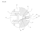
Fig. 4 is a cross-sectional view of a pressure control valve according to an embodiment of the present invention; -
Fig. 5 is a view illustrating a state where a pilot poppet illustrated inFig. 4 is seated; and -
Fig. 6 is a view illustrating a state where a pilot poppet illustrated inFig. 4 is lifted. -
- 1: inlet port
- 2: low-pressure path
- 3: sleeve
- 4: main poppet
- 5: piston spring
- 6: piston
- 7: main poppet spring
- 8: pressure chamber
- 9: valve seat
- 10: pilot poppet
- 11: pilot poppet spring
- 12: back chamber
- 13: low-pressure path
- 14: low-pressure path
- 15: orifice
- 20: orifice flow path
- 21: sliding portion
- 22: path
- 23: orifice
- Now, preferred embodiments of the present invention will be described in detail with reference to the accompanying drawings. The matters defined in the description, such as the detailed construction and elements, are nothing but specific details provided to assist those of ordinary skill in the art in a comprehensive understanding of the invention, and the present invention is not limited to the embodiments disclosed hereinafter.
- As illustrated in
Figs. 4 to 6 , a pressure control valve according to an embodiment of the present invention includes a sleeve 3 having an inlet port 1 formed thereon to receive an inflow of hydraulic fluid from a hydraulic pump P and a low-pressure path 2 formed thereon to communicate with a hydraulic tank T; a main poppet 4 detachably mounted on sleeve 3 to open and close the low-pressure path 2 with respect to the inlet port 1; a piston 6 slidably coupled to the main poppet 4 to be elastically supported by a piston spring 5; a main poppet spring 7 elastically biasing the main poppet 4 in an initial state by pressing the main poppet 4 to maintain the low-pressure path 2 closed with respect to the inlet port 1; a valve seat 9 installed in the sleeve 3 to face the main poppet 4 so as to form a pressure chamber 8; a pilot poppet 10 having an orifice flow path 20 formed thereon so as to control pressure in the pressure chamber 8 while maintaining a sliding state against the valve seat 9 when pressure that exceeds a predetermined pressure is generated in the pressure chamber 8 and thus the pilot poppet 10 is lifted from the valve seat 9 to open an internal flow path of the valve seat 9; and a pilot poppet spring 11 elastically biasing the pilot poppet 10 in an initial state by pressing the pilot poppet 10 to maintain the internal flow path of the valve seat 9 closed. - More preferably, the
orifice flow path 20 includes apath 22 formed in the center of thepilot poppet 10 that slides against thevalve seat 9 in an axis direction; and at least one orifice 23 (which is penetratingly formed at right angles to communicate with the path 22) formed on a slidingportion 21 of thepilot poppet 10 to communication with thepath 22. - Hereinafter, a usage example of the pressure control valve according to an embodiment of the present invention will be described in detail with reference to the accompanying drawings.
- As shown in
Figs. 4 to 6 , if high-pressure hydraulic fluid is supplied from the hydraulic pump P to the inlet port 1, the hydraulic fluid moves to thepressure chamber 8 after passing through an internal flow path of thepiston 6 of themain poppet 4 that is seated on thesleeve 3. At this time, thepilot poppet 10 is maintained in a seated state on thevalve seat 9 by an elastic force of thepilot poppet spring 11 that supports the pilot poppet 10 (the state illustrated inFig. 5 ). - Since the cross-sectional area of a left sliding portion is larger than the cross-sectional area of a portion seated on the
sleeve 3 in themain poppet 4 as described above and themain poppet 4 is supported by the elastic force of themain poppet spring 7, themain poppet 4 is pressed to the left and is maintained in a seated state on thesleeve 3. Through this, the low-pressure path 2 is maintained in a closed state with respect to the inlet port 1 (the state illustrated inFig. 4 ). - At this time, if the pressure of the hydraulic fluid that is supplied to the
pressure chamber 8 is gradually increased and reaches predetermined pressure of thepilot poppet spring 11, thepilot poppet 10 moves to the left. At this time, slidingportion 21 of thepilot poppet 10 is maintained in a sliding state by theinternal flow path 9a (the state illustrated inFig. 6 ). - Accordingly, the pressure of the
pressure chamber 8 passes through thepath 22 formed on the slidingportion 21 of thepilot poppet 10 and theorifice 23 is formed to communicate with thepath 22, and moves to aback chamber 12 through apocket 9b of thevalve seat 9. The hydraulic fluid, having moved to theback chamber 12, returns to the hydraulic tank T through a low-pressure path 13 formed on thevalve seat 9 and a low-pressure path 14 is formed on thesleeve 3. At this time, the pressure of thepressure chamber 8 is gradually lowered since the pressure is connected to the hydraulic tank T through theorifice flow path 20 that is open when thepilot poppet 10 is shifted. - Accordingly, since the pressure of the
pressure chamber 8 becomes lower than the pressure of inlet port 1, thepiston 6 moves to the left to be in contact with an end portion of thepilot poppet 10 due to a difference in pressure acting on the left and right pressure-receiving portions. - By contrast, in the
main poppet 4, the cross-sectional area of the left sliding portion becomes relatively larger than the cross-sectional area of the portion seated on thesleeve 3, and thus thesleeve 3 is maintained in the seated state even if the difference in pressure acting on the left and right pressure-receiving portions occurs. - If the
piston 6 comes in contact with the end portion of thepilot poppet 10 and the internal flow path of thepiston 6 is clogged, the hydraulic fluid in thepiston 6 moves to thepressure chamber 8 through thepath 22 formed on slidingportion 21 and the orifice 23 (for example, one of three orifices is open) that communicates with thepath 22 and through theinternal flow path 9a. - Due to this, the flow rate of the hydraulic fluid moving from the inlet port 1 to the
pressure chamber 8 is abruptly decreased, and the hydraulic fluid in thepressure chamber 8 is connected to thepocket 9b through thepath 22 formed on the slidingportion 21 and the orifice 23 (for example, one of three orifices is open). The hydraulic fluid, having moved to theback chamber 12, returns to the hydraulic tank T through the low-pressure path 13 formed on thevalve seat 9 and the low-pressure path 14 formed on thesleeve 3. Due to this, the pressure in thepressure chamber 8 is abruptly decreased, and the difference in pressure between the hydraulic fluid on the side of the inlet port 1 and the hydraulic fluid on the side of thepressure chamber 8 becomes greater. - That is, since the difference in pressure acting on the left and right pressure-receiving portions becomes larger than the pressure balancing due to the difference in cross-sectional area between the left and right light pressure-receiving portions of the
main poppet 4, themain poppet 4 moves to the left due to the pressure difference. - Accordingly, since the
main poppet 4 is lifted from thesleeve 3, the hydraulic fluid on the side of the inlet port 1 is relieved to the hydraulic tank T through low-pressure path 2 of thesleeve 3, the pressure of the hydraulic system can be constantly maintained. - At this time, if the
pilot poppet 10 moves to the left in the procedure in which thepilot poppet 10 is lifted from thevalve seat 9 and the high-pressure hydraulic fluid of thepressure chamber 8 is relieved to the hydraulic tank T as shown inFig. 6 , the slidingportion 21 of thepilot poppet 10 does not completely secede from theinternal flow path 9a, but is maintained in a continuously sliding state. - Accordingly, since the
pilot poppet 10, which is lifted from thevalve seat 9 during the relief operation, slides in theinternal flow path 9a of thevalve seat 9, no shaking occurs. Further, as a path for moving the hydraulic fluid from thepressure chamber 8 to the hydraulic tank T during the relief operation, thepath 22 is formed on thepilot poppet 10 and three separate orifice 23s are formed on the slidingportion 21 to communicate with thepath 22. - Through this, since the flow rate of the hydraulic fluid that returns from the
pressure chamber 8 to the hydraulic tank T is decreased, the occurrence of vibration and noise can be decreased, and stable pressure can be formed in the hydraulic system. - According to the pressure control valve as described above according to an embodiment of the present invention, when the pilot poppet is lifted from the valve seat during the relief operation, the pilot poppet continues to slide on the valve seat, and thus the relief operation is stably performed. Further, since the minimum amount of hydraulic fluid is relieved by the orifice flow path formed in the pilot poppet, the occurrence of vibration and noise due to the collision of the pilot poppet with the high-pressure hydraulic fluid can be prevented, and the durability of the control valve can be secured.
- As apparent from the above description, according to an embodiment of the present invention, since the minimum amount of hydraulic fluid is relieved to the hydraulic tank during the relief operation through the orifice flow path formed in the pilot poppet of the relief valve, the leakage of hydraulic fluid and impact occurring due to the high pressure and large capacity of the hydraulic fluid can be attenuated, and thus the occurrence of vibration and noise is minimized and the durability of the relief valve is secured.
- Further, since the pilot poppet is maintained in a sliding state on the valve seat during the relief operation, the pressure of the hydraulic system can be stably maintained. Further, the working efficiency is improved through the creation of an optimum working atmosphere, and an increase in manufacturing costs due to the regular replacement of pressure control valves can be prevented.
Claims (2)
- A pressure control valve comprising:a sleeve having an inlet port formed thereon to receive an inflow of hydraulic fluid from a hydraulic pump and a low-pressure path formed thereon to communicate with a hydraulic tank;a main poppet detachably mounted on the sleeve to open and close the low-pressure path with respect to the inlet port;a piston slidably coupled to the main poppet to be elastically supported by a piston spring;a main poppet spring elastically biasing the main poppet in an initial state by pressing the main poppet to maintain the low-pressure path closed with respect to the inlet port;a valve seat installed in the sleeve to face the main poppet so as to form a pressure chamber;a pilot poppet having an orifice flow path formed thereon so as to control pressure in the pressure chamber while maintaining a sliding state against the valve seat when pressure that exceeds a predetermined pressure is generated in the pressure chamber and thus the pilot poppet is lifted from the valve seat to open an internal flow path of the valve seat; anda pilot poppet spring elastically biasing the pilot poppet in an initial state by pressing the pilot poppet to maintain the internal flow path of the valve seat closed.
- The pressure control valve according to claim 1, wherein the orifice flow path comprises:a path formed in a center of the pilot poppet that slides against the valve seat in an axis direction; andat least one orifice formed on a sliding portion of the pilot poppet to communicate with the path.
Applications Claiming Priority (1)
| Application Number | Priority Date | Filing Date | Title |
|---|---|---|---|
| PCT/KR2010/003093 WO2011145753A1 (en) | 2010-05-17 | 2010-05-17 | Pressure control valve |
Publications (2)
| Publication Number | Publication Date |
|---|---|
| EP2573406A1 true EP2573406A1 (en) | 2013-03-27 |
| EP2573406A4 EP2573406A4 (en) | 2014-07-16 |
Family
ID=44991835
Family Applications (1)
| Application Number | Title | Priority Date | Filing Date |
|---|---|---|---|
| EP10851800.2A Withdrawn EP2573406A4 (en) | 2010-05-17 | 2010-05-17 | Pressure control valve |
Country Status (6)
| Country | Link |
|---|---|
| US (1) | US20130032225A1 (en) |
| EP (1) | EP2573406A4 (en) |
| JP (1) | JP5663084B2 (en) |
| KR (1) | KR20130086119A (en) |
| CN (1) | CN102859204A (en) |
| WO (1) | WO2011145753A1 (en) |
Cited By (1)
| Publication number | Priority date | Publication date | Assignee | Title |
|---|---|---|---|---|
| CN104358902A (en) * | 2014-10-15 | 2015-02-18 | 浙江华益机械有限公司 | Pressure safety valve |
Families Citing this family (22)
| Publication number | Priority date | Publication date | Assignee | Title |
|---|---|---|---|---|
| FR2986848B1 (en) * | 2012-02-13 | 2015-04-24 | Dubuis Et Cie | PRESSURE RELIEF VALVE FOR A HYDRAULIC PRESS TOOL, AND HYDRAULIC PRESS TOOL |
| JP2014185751A (en) * | 2013-03-25 | 2014-10-02 | Jatco Ltd | Control device and control method of continuously variable transmission |
| WO2014203369A1 (en) * | 2013-06-20 | 2014-12-24 | 株式会社 島津製作所 | Pressure control valve and control valve |
| WO2015037760A1 (en) * | 2013-09-13 | 2015-03-19 | 볼보 컨스트럭션 이큅먼트 에이비 | Construction machine float valve |
| WO2015054507A1 (en) | 2013-10-10 | 2015-04-16 | Pronutria, Inc. | Nutritive polypeptide production systems, and methods of manufacture and use thereof |
| US10378665B2 (en) * | 2015-09-18 | 2019-08-13 | Shimadzu Corporation | Pressure control valve |
| CN105650047B (en) * | 2016-02-26 | 2017-11-10 | 常熟华威履带有限公司 | A kind of hydraulicdirectional control valve device and the engineering machinery for carrying the device |
| EP3225799A1 (en) * | 2016-04-01 | 2017-10-04 | HUSCO Automotive Holdings LLC | Pilot operated piston oil cooling jet control valve |
| CN105805073B (en) * | 2016-05-29 | 2017-08-25 | 浙江大学 | A kind of plug-in overflow valve main valve that there is orientation to damp |
| CN107842615A (en) * | 2017-12-14 | 2018-03-27 | 山西三水河科技股份有限公司 | Super-pressure relief valve |
| CN108180177A (en) * | 2017-12-26 | 2018-06-19 | 邵立坤 | It is a kind of for the hydraulic valve of differential circuit and hydraulic differential circuit |
| CN107939766A (en) * | 2017-12-28 | 2018-04-20 | 邵立坤 | A kind of oil supplementation buffer valve |
| CN107939767A (en) * | 2017-12-28 | 2018-04-20 | 邵立坤 | A kind of oil supplementation buffer valve |
| US11242041B2 (en) * | 2018-04-23 | 2022-02-08 | Safran Landing Systems Canada Inc. | Slow response solenoid hydraulic valve, and associated systems and methods |
| CN110259752A (en) * | 2019-07-15 | 2019-09-20 | 宁波克泰液压有限公司 | Threaded insertion pilot depressurizes second level overflow valve |
| US11550344B2 (en) * | 2019-07-24 | 2023-01-10 | Emerson Automation Solutions Final Control US LP | Quick dome loading pilot valve |
| TWI730827B (en) * | 2020-06-24 | 2021-06-11 | 左天喬 | Pilot pressure relief valve |
| JP7643841B2 (en) * | 2020-07-01 | 2025-03-11 | カヤバ株式会社 | Relief Valve |
| CN111894926B (en) * | 2020-07-10 | 2022-04-29 | 乐清市东风煤矿设备有限公司 | Safety valve of hydraulic support |
| CN113775590B (en) * | 2021-10-18 | 2024-08-02 | 山东泰丰智能控制股份有限公司 | Constant pressure difference valve with buffering function |
| CN114233905B (en) * | 2021-12-28 | 2022-11-22 | 哈尔滨工业大学 | High-precision electro-hydraulic proportional overflow valve with multiple steady-state hydraulic compensation mechanisms |
| WO2024226649A1 (en) * | 2023-04-24 | 2024-10-31 | Kalsi Engineering, Inc. | Passive modulating design for fast responding control valves for high pressure gas applications |
Family Cites Families (28)
| Publication number | Priority date | Publication date | Assignee | Title |
|---|---|---|---|---|
| US1539617A (en) * | 1923-07-19 | 1925-05-26 | Manning Maxwell & Moore Inc | Check valve |
| US2503458A (en) * | 1946-02-11 | 1950-04-11 | Diesel Power Inc | Fuel injection pump |
| US2706490A (en) * | 1950-01-18 | 1955-04-19 | Nordberg Manufacturing Co | Variable retraction valve |
| DE1750834A1 (en) * | 1968-06-10 | 1971-04-29 | Gewerk Eisenhuette Westfalia | Pressure relief valve cartridge with piston O-ring seal |
| US3752188A (en) * | 1971-03-30 | 1973-08-14 | A Sage | Valve with controlled flow characteristics |
| US3908698A (en) * | 1974-03-07 | 1975-09-30 | Hans D Baumann | Variable resistance type throttling trim |
| JPS55112463A (en) * | 1979-02-20 | 1980-08-30 | Kayaba Ind Co Ltd | Pressure control valve |
| JPS5620877A (en) * | 1979-07-25 | 1981-02-26 | Kayaba Ind Co Ltd | Pressure control valve |
| DE3523548A1 (en) * | 1985-07-02 | 1987-01-15 | Gewerk Eisenhuette Westfalia | PRESSURE LIMIT VALVE |
| US4597410A (en) * | 1985-08-30 | 1986-07-01 | Husco International | Cross line relief valve mechanism |
| DE3637888A1 (en) * | 1986-11-06 | 1988-05-19 | Gewerk Eisenhuette Westfalia | PRESSURE LIMIT VALVE, IN PARTICULAR FOR HYDRAULIC EXTENSION SYSTEMS |
| JPH0750612Y2 (en) * | 1989-03-16 | 1995-11-15 | 株式会社小松製作所 | Pressure control valve |
| IT1235504B (en) * | 1989-08-04 | 1992-09-05 | Istituto Di Fotografia Biomedi | SELF-CLEANING VARIABLE FLOW VALVE PREFERABLY FOR VENTRICULAR DERIVATIONS OF LIQUOR CEPHALORACHIDIANO. |
| US4971099A (en) * | 1989-12-15 | 1990-11-20 | Cooper Industries, Inc. | Pressure balanced cartridge choke valve |
| JP2582125Y2 (en) * | 1992-04-27 | 1998-09-30 | 東芝機械株式会社 | Relief valve |
| DE4302080C1 (en) * | 1993-01-27 | 1994-08-18 | Vos Richard Grubenausbau Gmbh | Small pressure relief valve with high flow rate |
| JP2593802Y2 (en) * | 1993-08-02 | 1999-04-19 | 東芝機械株式会社 | Pilot poppet type pressure control valve |
| KR100493325B1 (en) * | 2001-12-18 | 2005-06-07 | 볼보 컨스트럭션 이키프먼트 홀딩 스웨덴 에이비 | hydraulic relief valve |
| US20030131889A1 (en) * | 2002-01-11 | 2003-07-17 | Kim Jin Wook | Pilot poppet type pressure control valve |
| US20040118462A1 (en) * | 2002-12-19 | 2004-06-24 | Baumann Hans D. | Control valve with low noise and enhanced flow characteristics |
| JP2005016568A (en) * | 2003-06-24 | 2005-01-20 | Kayaba Ind Co Ltd | Control valve device |
| KR100586023B1 (en) * | 2004-02-12 | 2006-06-01 | 볼보 컨스트럭션 이키프먼트 홀딩 스웨덴 에이비 | Relief valve |
| KR100764119B1 (en) * | 2004-02-25 | 2007-10-08 | 볼보 컨스트럭션 이키프먼트 홀딩 스웨덴 에이비 | Pilot Poppet Relief Valve |
| KR100652875B1 (en) * | 2005-09-15 | 2006-12-01 | 볼보 컨스트럭션 이키프먼트 홀딩 스웨덴 에이비 | Hydraulic relief valve |
| US7644726B1 (en) * | 2006-09-26 | 2010-01-12 | Kermit L. Achterman, & Associates, Inc. | Self-cleaning flow shut off valve |
| KR100826627B1 (en) * | 2007-03-27 | 2008-05-02 | 볼보 컨스트럭션 이키프먼트 홀딩 스웨덴 에이비 | Heavy Duty Relief Valve |
| KR100961431B1 (en) * | 2008-02-25 | 2010-06-09 | 볼보 컨스트럭션 이키프먼트 홀딩 스웨덴 에이비 | Pressure control valve |
| KR100950571B1 (en) * | 2009-02-27 | 2010-04-01 | (주)동우정공 | Relief valve of heavy equipment |
-
2010
- 2010-05-17 CN CN2010800662276A patent/CN102859204A/en active Pending
- 2010-05-17 WO PCT/KR2010/003093 patent/WO2011145753A1/en not_active Ceased
- 2010-05-17 US US13/641,258 patent/US20130032225A1/en not_active Abandoned
- 2010-05-17 KR KR20127025422A patent/KR20130086119A/en not_active Ceased
- 2010-05-17 EP EP10851800.2A patent/EP2573406A4/en not_active Withdrawn
- 2010-05-17 JP JP2013511086A patent/JP5663084B2/en not_active Expired - Fee Related
Cited By (1)
| Publication number | Priority date | Publication date | Assignee | Title |
|---|---|---|---|---|
| CN104358902A (en) * | 2014-10-15 | 2015-02-18 | 浙江华益机械有限公司 | Pressure safety valve |
Also Published As
| Publication number | Publication date |
|---|---|
| WO2011145753A1 (en) | 2011-11-24 |
| KR20130086119A (en) | 2013-07-31 |
| JP2013527398A (en) | 2013-06-27 |
| EP2573406A4 (en) | 2014-07-16 |
| JP5663084B2 (en) | 2015-02-04 |
| US20130032225A1 (en) | 2013-02-07 |
| CN102859204A (en) | 2013-01-02 |
Similar Documents
| Publication | Publication Date | Title |
|---|---|---|
| US20130032225A1 (en) | Pressure control valve | |
| EP1890064A2 (en) | Pressure control valve | |
| US9103355B2 (en) | Flow control valve for construction machine | |
| EP2573282B1 (en) | Hydraulic pressure-regulating valve for construction equipment | |
| KR20050086281A (en) | Pilot poppet type relief valve | |
| US20170241563A1 (en) | Valve assembly and method | |
| EP1820996A3 (en) | Damping force control valve and shock absorber using the same | |
| JP5943942B2 (en) | Actuator | |
| JP6017850B2 (en) | valve | |
| WO2015159201A1 (en) | Variable pressure pump with hydraulic passage | |
| CN110285104B (en) | Fixed-difference overflow valve and engineering machinery | |
| WO2016181755A1 (en) | High-pressure fuel pump | |
| US9964105B2 (en) | Diaphragm pump having position control | |
| CN102444743B (en) | Volume booster with stabilized trim | |
| JP5449941B2 (en) | Poppet valve with inclined purge hole and method for reducing pressure inside poppet valve | |
| CN108603497A (en) | Active surge-chamber | |
| KR20170052685A (en) | Load sensing valve device | |
| JP6068203B2 (en) | Pressure control valve | |
| JP2013117293A (en) | Flow control valve | |
| US11957089B2 (en) | Zero leak pilot operated valve having two seats | |
| KR20120006517U (en) | Volume booster with low vibration and low noise | |
| US20180298922A1 (en) | Valve device | |
| CN116292479B (en) | Straight-through high-pressure overflow valve with pressure impact resistance | |
| WO2013112300A1 (en) | Guiding deformation in seated hydraulic metering devices | |
| EP2829942A3 (en) | Air purging pressure regulating valve |
Legal Events
| Date | Code | Title | Description |
|---|---|---|---|
| PUAI | Public reference made under article 153(3) epc to a published international application that has entered the european phase |
Free format text: ORIGINAL CODE: 0009012 |
|
| 17P | Request for examination filed |
Effective date: 20121001 |
|
| AK | Designated contracting states |
Kind code of ref document: A1 Designated state(s): AL AT BE BG CH CY CZ DE DK EE ES FI FR GB GR HR HU IE IS IT LI LT LU LV MC MK MT NL NO PL PT RO SE SI SK SM TR |
|
| DAX | Request for extension of the european patent (deleted) | ||
| A4 | Supplementary search report drawn up and despatched |
Effective date: 20140618 |
|
| RIC1 | Information provided on ipc code assigned before grant |
Ipc: F16K 17/10 20060101ALI20140612BHEP Ipc: E02F 9/22 20060101ALI20140612BHEP Ipc: F16K 1/42 20060101ALI20140612BHEP Ipc: F16K 47/04 20060101ALI20140612BHEP Ipc: F15B 13/02 20060101ALI20140612BHEP Ipc: F16K 17/196 20060101ALI20140612BHEP Ipc: F15B 13/042 20060101AFI20140612BHEP |
|
| 17Q | First examination report despatched |
Effective date: 20170918 |
|
| STAA | Information on the status of an ep patent application or granted ep patent |
Free format text: STATUS: THE APPLICATION IS DEEMED TO BE WITHDRAWN |
|
| 18D | Application deemed to be withdrawn |
Effective date: 20180130 |