EP2573374A1 - Vaporization method and vaporization apparatus used for vaporization method, and vaporization system provided with vaporization apparatus - Google Patents
Vaporization method and vaporization apparatus used for vaporization method, and vaporization system provided with vaporization apparatus Download PDFInfo
- Publication number
- EP2573374A1 EP2573374A1 EP11792108A EP11792108A EP2573374A1 EP 2573374 A1 EP2573374 A1 EP 2573374A1 EP 11792108 A EP11792108 A EP 11792108A EP 11792108 A EP11792108 A EP 11792108A EP 2573374 A1 EP2573374 A1 EP 2573374A1
- Authority
- EP
- European Patent Office
- Prior art keywords
- liquid
- heat exchange
- section
- vaporizing
- gas
- Prior art date
- Legal status (The legal status is an assumption and is not a legal conclusion. Google has not performed a legal analysis and makes no representation as to the accuracy of the status listed.)
- Withdrawn
Links
- 230000008016 vaporization Effects 0.000 title claims abstract description 192
- 238000009834 vaporization Methods 0.000 title claims abstract description 64
- 239000007788 liquid Substances 0.000 claims abstract description 221
- 230000005514 two-phase flow Effects 0.000 claims abstract description 45
- 230000001174 ascending effect Effects 0.000 claims abstract description 39
- 238000000034 method Methods 0.000 claims description 11
- 238000010438 heat treatment Methods 0.000 claims description 5
- 239000007789 gas Substances 0.000 description 63
- 239000003949 liquefied natural gas Substances 0.000 description 30
- 239000002184 metal Substances 0.000 description 27
- 239000002893 slag Substances 0.000 description 11
- 239000007791 liquid phase Substances 0.000 description 8
- 238000009835 boiling Methods 0.000 description 6
- 238000010586 diagram Methods 0.000 description 5
- 239000012530 fluid Substances 0.000 description 4
- 239000012071 phase Substances 0.000 description 4
- 230000000717 retained effect Effects 0.000 description 3
- 230000015572 biosynthetic process Effects 0.000 description 2
- 238000001816 cooling Methods 0.000 description 2
- VNWKTOKETHGBQD-UHFFFAOYSA-N methane Chemical compound C VNWKTOKETHGBQD-UHFFFAOYSA-N 0.000 description 2
- 238000011144 upstream manufacturing Methods 0.000 description 2
- 239000006200 vaporizer Substances 0.000 description 2
- IJGRMHOSHXDMSA-UHFFFAOYSA-N Atomic nitrogen Chemical compound N#N IJGRMHOSHXDMSA-UHFFFAOYSA-N 0.000 description 1
- UFHFLCQGNIYNRP-UHFFFAOYSA-N Hydrogen Chemical compound [H][H] UFHFLCQGNIYNRP-UHFFFAOYSA-N 0.000 description 1
- 230000006835 compression Effects 0.000 description 1
- 238000007906 compression Methods 0.000 description 1
- 229910001873 dinitrogen Inorganic materials 0.000 description 1
- 239000000203 mixture Substances 0.000 description 1
- 238000012986 modification Methods 0.000 description 1
- 230000004048 modification Effects 0.000 description 1
- 239000003345 natural gas Substances 0.000 description 1
Images




Classifications
-
- F—MECHANICAL ENGINEERING; LIGHTING; HEATING; WEAPONS; BLASTING
- F01—MACHINES OR ENGINES IN GENERAL; ENGINE PLANTS IN GENERAL; STEAM ENGINES
- F01K—STEAM ENGINE PLANTS; STEAM ACCUMULATORS; ENGINE PLANTS NOT OTHERWISE PROVIDED FOR; ENGINES USING SPECIAL WORKING FLUIDS OR CYCLES
- F01K21/00—Steam engine plants not otherwise provided for
- F01K21/02—Steam engine plants not otherwise provided for with steam-generation in engine-cylinders
-
- F—MECHANICAL ENGINEERING; LIGHTING; HEATING; WEAPONS; BLASTING
- F02—COMBUSTION ENGINES; HOT-GAS OR COMBUSTION-PRODUCT ENGINE PLANTS
- F02G—HOT GAS OR COMBUSTION-PRODUCT POSITIVE-DISPLACEMENT ENGINE PLANTS; USE OF WASTE HEAT OF COMBUSTION ENGINES; NOT OTHERWISE PROVIDED FOR
- F02G1/00—Hot gas positive-displacement engine plants
- F02G1/04—Hot gas positive-displacement engine plants of closed-cycle type
- F02G1/043—Hot gas positive-displacement engine plants of closed-cycle type the engine being operated by expansion and contraction of a mass of working gas which is heated and cooled in one of a plurality of constantly communicating expansible chambers, e.g. Stirling cycle type engines
- F02G1/053—Component parts or details
- F02G1/055—Heaters or coolers
-
- F—MECHANICAL ENGINEERING; LIGHTING; HEATING; WEAPONS; BLASTING
- F28—HEAT EXCHANGE IN GENERAL
- F28D—HEAT-EXCHANGE APPARATUS, NOT PROVIDED FOR IN ANOTHER SUBCLASS, IN WHICH THE HEAT-EXCHANGE MEDIA DO NOT COME INTO DIRECT CONTACT
- F28D7/00—Heat-exchange apparatus having stationary tubular conduit assemblies for both heat-exchange media, the media being in contact with different sides of a conduit wall
- F28D7/0058—Heat-exchange apparatus having stationary tubular conduit assemblies for both heat-exchange media, the media being in contact with different sides of a conduit wall the conduits for only one medium being tubes having different orientations to each other or crossing the conduit for the other heat exchange medium
-
- F—MECHANICAL ENGINEERING; LIGHTING; HEATING; WEAPONS; BLASTING
- F28—HEAT EXCHANGE IN GENERAL
- F28D—HEAT-EXCHANGE APPARATUS, NOT PROVIDED FOR IN ANOTHER SUBCLASS, IN WHICH THE HEAT-EXCHANGE MEDIA DO NOT COME INTO DIRECT CONTACT
- F28D7/00—Heat-exchange apparatus having stationary tubular conduit assemblies for both heat-exchange media, the media being in contact with different sides of a conduit wall
- F28D7/06—Heat-exchange apparatus having stationary tubular conduit assemblies for both heat-exchange media, the media being in contact with different sides of a conduit wall the conduits having a single U-bend
-
- F—MECHANICAL ENGINEERING; LIGHTING; HEATING; WEAPONS; BLASTING
- F28—HEAT EXCHANGE IN GENERAL
- F28F—DETAILS OF HEAT-EXCHANGE AND HEAT-TRANSFER APPARATUS, OF GENERAL APPLICATION
- F28F1/00—Tubular elements; Assemblies of tubular elements
- F28F1/10—Tubular elements and assemblies thereof with means for increasing heat-transfer area, e.g. with fins, with projections, with recesses
- F28F1/12—Tubular elements and assemblies thereof with means for increasing heat-transfer area, e.g. with fins, with projections, with recesses the means being only outside the tubular element
- F28F1/24—Tubular elements and assemblies thereof with means for increasing heat-transfer area, e.g. with fins, with projections, with recesses the means being only outside the tubular element and extending transversely
- F28F1/32—Tubular elements and assemblies thereof with means for increasing heat-transfer area, e.g. with fins, with projections, with recesses the means being only outside the tubular element and extending transversely the means having portions engaging further tubular elements
-
- F—MECHANICAL ENGINEERING; LIGHTING; HEATING; WEAPONS; BLASTING
- F28—HEAT EXCHANGE IN GENERAL
- F28F—DETAILS OF HEAT-EXCHANGE AND HEAT-TRANSFER APPARATUS, OF GENERAL APPLICATION
- F28F13/00—Arrangements for modifying heat-transfer, e.g. increasing, decreasing
-
- F—MECHANICAL ENGINEERING; LIGHTING; HEATING; WEAPONS; BLASTING
- F02—COMBUSTION ENGINES; HOT-GAS OR COMBUSTION-PRODUCT ENGINE PLANTS
- F02G—HOT GAS OR COMBUSTION-PRODUCT POSITIVE-DISPLACEMENT ENGINE PLANTS; USE OF WASTE HEAT OF COMBUSTION ENGINES; NOT OTHERWISE PROVIDED FOR
- F02G2256/00—Coolers
-
- F—MECHANICAL ENGINEERING; LIGHTING; HEATING; WEAPONS; BLASTING
- F28—HEAT EXCHANGE IN GENERAL
- F28D—HEAT-EXCHANGE APPARATUS, NOT PROVIDED FOR IN ANOTHER SUBCLASS, IN WHICH THE HEAT-EXCHANGE MEDIA DO NOT COME INTO DIRECT CONTACT
- F28D21/00—Heat-exchange apparatus not covered by any of the groups F28D1/00 - F28D20/00
- F28D2021/0019—Other heat exchangers for particular applications; Heat exchange systems not otherwise provided for
- F28D2021/0061—Other heat exchangers for particular applications; Heat exchange systems not otherwise provided for for phase-change applications
- F28D2021/0064—Vaporizers, e.g. evaporators
Definitions
- the present invention relates to a vaporization method for vaporizing liquid while recovering power using a Stirling engine, a vaporization apparatus used for the vaporization method, and a vaporization system provided with the vaporization apparatus.
- a Stirling engine has been known in the past.
- the Stirling engine includes a heat exchange unit for hot energy and a heat exchange unit for cold energy. Hot energy is supplied to the heat exchange unit for hot energy and cold energy is supplied to the heat exchange for cold energy, whereby the Stirling engine obtains power.
- a technology is known for vaporizing liquid while recovering power by adopting cold energy (latent heat) of the liquid as the cold energy supplied to the Stirling engine of this type (e.g., Patent Document 1).
- the Stirling engine according to Patent Document 1 vaporizes liquid (LNG: liquefied natural gas) while recovering power by applying the heat of vaporization to the liquid.
- a Stirling engine 102 of Patent Document 1 includes, as shown in Fig. 7 , a cooler 104 provided on the outer side of a head (a heat exchange unit for cold energy) of a displacer cylinder 106 of the Stirling engine 102.
- the cooler 104 cools the head of the displacer cylinder 106 with the latent heat of the LNG supplied to the inside of the cooler 104.
- the LNG from which the latent heat is transferred (to which the heat of vaporization is applied) vaporizes.
- the Stirling engine 102 of Patent Document 1 complicated processing is necessary in order to obtain target gas from the liquid (LNG) at high efficiency.
- the Stirling engine 102 of Patent Document 1 is configured to immerse the head of the Displacer cylinder 106 in the liquid stored in the cooler 104 in order to bring the liquid into contact with the displacer cylinder 106. Therefore, gas already vaporized and gas not vaporized yet are separated. In order to obtain target gas at high efficiency in a state in which the liquid and the gas are separated in this way, as shown in Fig.
- Patent Document 1 Japanese Patent Application Laid-Open No. H11-22550
- An object of the present invention is to provide a vaporization method that can obtain target gas at high efficiency using a Stirling engine without requiring a complicated process and complicated equipment, a vaporization apparatus used for the vaporization method, and a vaporization system provided with the vaporization apparatus.
- a method of vaporizing liquid using a Stirling engine including a heat exchange unit for cold energy including: a preparing step of preparing a conduit that covers at least a part of the heat exchange unit for cold energy of the Stirling engine and is capable of forming an ascending flow of the liquid flowing from a bottom to a top of the heat exchange unit for cold energy; and a vaporizing step of feeding the liquid in the conduit to thereby form the ascending flow and bringing the liquid into contact with the Stirling engine to vaporize the liquid.
- a flowing direction of the ascending flow is adjusted to be an angle set in advance for suppressing occurrence of separated flows of the liquid and gas in the conduit.
- the liquid is fed at a flow velocity at which a gas-liquid two-phase flow in which the liquid and the gas are mixed is formed in the conduit.
- Fig. 1 is a schematic diagram showing an overall configuration of a vaporization system according to an embodiment of the present invention.
- Fig. 2 is a sectional view showing in enlargement a vaporizing tube shown in Fig. 1 .
- Fig. 3 is a III-III line sectional view of Fig. 2 .
- a vaporization system 1 includes a Stirling engine 2, a vaporizing tube 4 attached to the Stirling engine 2, a pump 3 that supplies LNG (liquefied natural gas) to the vaporizing tube 4, and a vaporizing heater 5 that vaporizes or heats fluid led out from the vaporizing tube 4.
- LNG liquefied natural gas
- a vaporizing heater 5 that vaporizes or heats fluid led out from the vaporizing tube 4.
- the Stirling engine 2 and the vaporizing tube 4 configure a vaporization apparatus in this embodiment.
- the Stirling engine 2 includes a heat exchange unit for cold energy 6 for cooling working gas (e.g., hydrogen gas or nitrogen gas) in a not-shown displacer cylinder and a heat exchange unit for hot energy 7 for heating the gas in the displacer cylinder, a displacer piston 8 movable in the displacer cylinder, a power piston 9 movable according to compression or expansion of the gas in the displacer cylinder, and a crankshaft 10 to which the displacer piston 8 and the power piston 9 are coupled.
- working gas e.g., hydrogen gas or nitrogen gas
- the displacer piston 8 moves in a direction for increasing the volume on the heat exchange unit for hot energy 7. Then, according to the increase in the gas heated by the heat exchange unit for hot energy 7, the power piston 9 moves in a direction for increasing the volume of the displacer cylinder. According to the movement, the displacer piston 8 moves in a direction for increasing the volume of the heat exchange unit for cold energy 6. This action is repeatedly performed, whereby power used for a rotating action of the crankshaft 10 can be recovered.
- the heat exchange unit for cold energy 6 includes a U-shaped metal tube (an encapsulating section) 6b in which the working gas circulates and six metal plates (extending sections) 6a heat-conductibly coupled to the metal tube 6b.
- Each of the metal plates 6a is arranged in a standing posture.
- the metal plates 6a are arranged substantially in parallel to one another in a state in which the metal plates 6a are pierced through by the metal tube 6b.
- the metal plates 6a are arranged such that regions on one side (the upper side in Figs. 1 and 2 ) are long compared with regions on the other side (the lower side in Figs. 1 and 2 ) with respect to the metal tube 6b.
- the vaporizing tube 4 is a conduit for vaporizing the LNG.
- the LNG circulates inside the vaporizing tube 4 in a state in which the vaporizing tube 4 is attached to the Stirling engine 2, the LNG in the vaporizing tube 4 vaporizes with the heat of vaporization received from the heat exchange unit for cold energy 6.
- the vaporizing tube 4 includes a lead-in section 11 for leading in the LNG from the pump 3, a vaporizing section (a heat exchange section or an auxiliary heat exchange section) 12 that cools the heat exchange unit for cold energy 6 of the Stirling engine 2 with the LNG from the lead-in section 11, and a lead-out section 14 for leading out the LNG from the vaporizing section 12.
- a channel in the vaporizing tube 4 has a shape for circulating liquid in a direction having an upward component in the entire range from the lead-in section 11 to the lead-out section 14.
- the shape for circulating liquid in a direction having an upward component in the entire range from the lead-in section 11 to the lead-out section 14' means the shape of the channel that can be arranged in a state not including a section where a position on an upstream side is higher than a position on a downstream side. This means that the shape is not limited to a linear shape and includes a curved shape.
- the vaporizing section 12 houses the distal end of the metal tube 6b and the metal plates 6a. Specifically, in the vaporizing section 12, the metal plates 6a are arranged to extend along the axis of the vaporizing tube 4 in a state in which the sidewalls of the metal plates 6a are pierced through by the metal tube 6b.
- the vaporizing section 12 houses the metal plates 6a in a posture in which portions on one side (the upper side in Figs. 1 and 2 ) of the metal plates 6a extending longer than the other side (the lower side of Figs. 1 and 2 ) with respect to the metal tube 6b face the lead-in section 14.
- the metal plates 6a have a shape extending long toward the downstream side in a flowing direction of the LNG from the metal tube 6b.
- the vaporizing tube 4 is attached to the Stirling engine 2 to form a vertical ascending flow F1 (see Fig. 1 ).
- the vaporizing tube 4 is attached to the Stirling engine 2 to have a posture in which the lead-in section 11 is on the lower side and the lead-out section 14 is on the upper side and axes thereof extend along the vertical direction in the vaporizing section 12.
- the vertical ascending flow F1 of the fluid flowing upward is formed in the vaporizing tube 4
- separated flows (a wavy flow and a stratified flow: see Fig. 4 ) are not generated.
- a gas-liquid two-phase flow in which the liquid and the gas are mixed is formed.
- the vaporizing tube 4 has an inner diameter dimension set to generate an air bubble flow concerning a range E1 (see Fig. 2 ) of the lead-in section 11 and a range E2 (see Fig. 2 : the heat exchange section) in which the metal tube 6b and the liquid from the pump 3 come into contact with each other, generate an air bubble flow, a slag flow, or an intermittent flow concerning a range E3 (see Fig. 2 : the auxiliary heat exchange section) further on the downstream side than the metal tube 6b in the vaporizing section 12, and generate an intermittent flow or an annular flow concerning a range E4 of the lead-out section 14 in a fluidized state of the gas-liquid two-phase flow in the vertical ascending flow F1 shown in Fig. 5 .
- the air bubble flow means a flow of air bubbles dispersing in the liquid when the flow velocity of the gas is small.
- the intermittent flow means a flow including a slag flow in which liquid slag containing small air bubbles and gas slag alternately flow and a chum flow in which the flow velocity of the liquid increases and a large number of large and small air bubbles are present in the liquid.
- the annular flow means that the liquid flows along a tube wall and the gas continuously flows in a tube center. A method of setting the inner diameter dimension of the vaporizing tube 4 for forming the fluidized state is explained below.
- an inner diameter dimension d serving as a flow velocity parameter U L / ⁇ 2 of a liquid phase is calculated on the basis of Formula 1 below such that the fluidized state of the gas-liquid two-phase flow shown in Fig. 5 is the air bubble flow.
- U L is a flow velocity in the liquid phase
- ⁇ 2 is a correction coefficient set to have a value of 1 when the inner diameter of the conduit is 2.54 cm
- d 0 is a reference inner diameter dimension (2.54 cm).
- the inner diameter dimension of the range E1 is set smaller than the inner diameter dimension of the range E2.
- the flow velocity in the range E1 increases. Consequently, the density of the liquid in the gas-liquid two-phase flow in the range E1 is equal to or higher than the density of the liquid in the gas-liquid two-phase flow in the range E2. Therefore, it is possible to keep large cold energy of the gas-fluid two-phase flow in the range E1, which is a pre-stage of the range E2, i.e., the heat exchange section. As a result, it is possible to further improve the efficiency of heat exchange.
- the flow velocity parameter U L / ⁇ 2 of the liquid phase is calculated on the basis of Formula 1 above and a flow velocity parameter U G / ⁇ 1 of the gas phase is calculated on the basis of Formula 2 below such that the fluidized state of the gas-liquid two-phase flow generated in the range E2 is the air bubble flow, the slag flow, or the intermittent flow.
- the inner diameter dimension d of the range E3 is set to satisfy these conditions.
- the flow velocity parameter U L / ⁇ 2 of the liquid phase concerning the air bubble flow, the slag flow, or the intermittent flow is the same as Formula 1 above.
- U G is the flow velocity of the gas phase
- ⁇ 1 is a correction coefficient set to have a value of 1 when the inner diameter of the conduit is 2.54 cm
- ⁇ is an angle (in this embodiment, 90°) formed by the flowing direction of the LNG and the horizontal direction.
- ⁇ ⁇ 1 d / d° 0.8 ⁇ 1 - 0.65 cos ⁇
- the inner diameter dimension d is set such that the fluidized state of the gas-liquid two-phase flow generated in the range E3 is the intermittent flow or the annular flow. Specifically, when the intermittent flow is formed, the flow velocity parameter U L / ⁇ 2 of the liquid phase is calculated on the basis of Formula 1 above, the flow velocity parameter U G / ⁇ 1 of the gas phase is calculated on the basis of Formula 2 above, and the inner dimension parameter d of the range E4 is set to satisfy these conditions.
- ⁇ G is the density of the gas
- ⁇ G 0 is 1.3 kg ⁇ m -3
- ⁇ 0 is ( ⁇ L 0 - ⁇ G 0 )
- ⁇ is ( ⁇ L - ⁇ G )
- ⁇ 0 is 0.07 N ⁇ m -1
- ⁇ is surface tension.
- ⁇ ⁇ 1 ⁇ G ⁇ ° ⁇ G 0.23 ⁇ ⁇ ⁇ ⁇ ⁇ ⁇ ⁇ ⁇ ° 0.11 ⁇ ⁇ ⁇ ⁇ ° 0.11 ⁇ d d° 0.415
- the vaporizing tube 4 that covers the heat exchange unit for cold energy 6 of the Stirling engine 2 and is capable of forming a vertical ascending flow of the liquid flowing from the bottom to the top of the heat exchange unit for cold energy 6 is prepared (a preparing step).
- the pump 3 is provided below the vaporizing tube 4 and the vaporizing heater 5 is provided above the vaporizing tube 4.
- the LNG is ejected from the pump 3, whereby the vertical ascending flow F1 of the LNG led in from below (the lead-in section 11) the vaporizing tube 4 and led out from above (the lead-out section 14) the vaporizing tube 4 is formed.
- the LNG changes to an air bubble flow in the lead-in section 11 (the range E1) to be led into the vaporizing section 12.
- the liquid not vaporized yet in the LNG led into the vaporizing section 12 in the state of the air bubble flow comes into contact with the metal tube 6b in the range E2 and receives the heat of vaporization from the metal tube 6b to thereby vaporize (a vaporizing step). Consequently, in the range E3 located further on the downstream side than the range E2, as an air bubble flow same as that in the range E2 or a slag flow or an intermittent flow having a less liquid phase compared with the range E2 is formed.
- the liquid not vaporized yet in the gas-liquid two-phase flow led in from the range E2 comes into contact with the metal plates 6a and receives the heat of vaporization from the metal plates 6a to thereby vaporize.
- the gas-liquid two-phase flow from the range E3 is led out from the lead-out section 14 in a state in which the gas-liquid two-phase flow is changed to an intermittent flow or an annular flow in the range E4.
- the vaporizing heater 5 is provided on the lead-out section 14 and the gas-liquid two-phase flow led out from the lead-out section 14 is guided to the vaporizing heater 5 in the form of the ascending flow F1 (a guiding step). Therefore, the liquid not vaporized by the heat exchange unit for cold energy 6 of the Stirling engine 2 is guided to the vaporizing heater 5 together with the liquid already vaporized and is vaporized in the vaporizing heater 5. On the other hand, the gas is heated in the vaporizing heater 5.
- 'an angle set in advance for suppressing occurrence of separated flows of the liquid and gas in the conduit' means an angle ⁇ that satisfies the condition of Formula 4 below.
- ⁇ is an angle formed by the flowing direction of the ascending flow and the horizontal direction
- d is the inner diameter (the diameter) of the conduit
- 1 is a channel length of the gas-liquid two-phase flow in the conduit.
- the ascending flow is formed vertically.
- the ascending flow is not limited to be vertically formed. It is possible to suppress the occurrence of the separated flows if the flowing direction of the ascending flow is adjusted to be fit within a range of the angle ⁇ of Formula 4 below. sin ⁇ > d l
- the liquid is supplied from the pump 3 at a flow velocity at which the gas-liquid two-phase flow is formed in the vaporizing tube 4. Therefore, it is possible to effectively vaporize the liquid contained in the gas-liquid two-phase flow with the heat of vaporization received from the heat exchange unit for cold energy 6 of the Stirling engine 2 while effectively circulating the gas-liquid two-phase flow in the state in which the gas and the liquid are mixed.
- the liquid is supplied from the pump 3 at the flow velocity at which the gas-liquid two-phase flow is formed in the vaporizing tube 4. Therefore, it is possible to effectively vaporize the liquid contained in the gas-liquid two-phase flow with the heat of vaporization received from the heat exchange unit for cold energy 6 of the Stirling engine 2 while effectively circulating the gas-liquid two-phase flow in the state in which the gas and the liquid are mixed.
- the embodiment it is possible to perform vaporization of the remaining liquid while collecting the target gas by circulating the liquid and the gas as the gas-liquid two-phase flow of the vertical ascending flow F1. Therefore, it is possible to obtain the target gas at high efficiency without requiring a complicated process and complicated equipment.
- liquid in which a plurality of components having different boiling points are mixed such as the LNG is supplied to the vaporizing tube 4
- low-boiling point components can be easily vaporized by the heat of vaporization from the Stirling engine 2.
- high-boiling point components may be unable to be sufficiently vaporized by the heat of vaporization from the Stirling engine 2.
- the embodiment is a configuration for forming the air bubble flow in the range E2 (the heat exchange section) and forming the air bubble flow, the slag flow, or the intermittent flow in the range E3 (the auxiliary heat exchange section).
- the embodiment is a configuration in which the inner diameter dimension of the lead-in section 11 is set smaller than the inner diameter dimension of the vaporizing section 12. With this configuration, it is possible to set the density of the liquid in the lead-in section 11 larger than the density of the liquid in the vaporizing section 12. Therefore, it is possible to maintain a state in which a lot of cold energy is retained at a stage before the liquid is guided to the vaporizing section 12. As a result, it is possible to more effectively perform vaporization in the vaporizing section 12.
- the heat exchange unit for cold energy 6 includes the metal tube (the encapsulating section) 6b and the plurality of metal plates (the extending sections) 6a.
- the gas-liquid two-phase flow is formed in the range E2 (the heat exchanging section) and the range E3 (the auxiliary heat exchanging section). With this form, it is possible to effectively vaporize the liquid in the range E3 in addition to the range E2.
- the vaporizing tube 4 including the linear channel in which the lead-in section 11, the vaporizing section 12, and the lead-out section 14 are coaxially arranged is explained.
- the channel in the vaporizing tube 4 is not limited to the linear shape and may be, for example, a curved shape as long as the shape is the shape of the channel that can be arranged in a state in which the channel does not have a section where the position on the upstream side of the channel is higher than the position on the downstream side.
- the cylindrical vaporizing tube 4 is explained.
- the sectional shape of the vaporizing tube is not limited to a circle and may be, for example, a rectangle as shown in Fig. 6 .
- a representative diameter in the case in which a cylindrical container having a sectional area equal to the sectional area of the vaporizing tube 22 is assumed can be adopted as the inner diameter dimension d. This is because, since the sectional area is equal irrespective of the shape of the sectional area, a state of the gas-liquid two-phase flow is approximated.
- the diameter dimension of the vaporizing tube 4 in the case in which LNG having 0.3 MPaG and -160°C is supplied at a flow rate of 1 t/h is explained below. It is assumed that the LNG supplied to the vaporizing tube 4 is heated to -133°C by heat exchange with the heat exchange unit for cold energy 6 of the Stirling engine 2.
- the density of the LNG at 0.3 MPaG and -160°C is 460 kg/m 3 . Therefore, the flow rate of the LNG in the range E1 is 0.604x 10 -3 m 3 /sec. Since the diameter dimension d of the range E1 is 40 mm, the flow velocity U L is about 0.5 m/sec. Therefore, when the diameter dimension of the range E1 is set to 40 mm, the condition (the flow velocity U L ⁇ 4.724 m/sec) is satisfied.
- a value of the flow velocity parameter U L / ⁇ 2 is required to be smaller than 3 (see Fig. 5 ). If the diameter dimension d in the range E2 is set to 500 mm, ⁇ 2 (see Formula 1) is 19.69. Therefore, the flow velocity U L is required to be smaller than 59.06 m/sec.
- the density of the LNG at 0.3 MPaG and -160°C is 460 kg/m 3 . Therefore, the flow rate of the LNG in the range E2 is 0.604 ⁇ 10 -3 m 3 /sec. Since the diameter dimension d of the range E2 is 500 mm, the flow velocity U L is about 3.1 ⁇ 10 -3 m/sec. Therefore, when the diameter dimension of the range E2 is set to 500 mm, the condition (the flow velocity U L , ⁇ 59.06 m/sec) is satisfied.
- the flow rate of the LNG in the range E3 is 0.058 m 3 /sec. Since the diameter dimension d of the range E3 is 500 mm, the flow velocity U G is about 0.3 m/sec.
- the flow rate of the LNG in the range E4 is 0.058 m 3 /sec. Since the diameter dimension d of the range E4 is 120 mm, the flow velocity U G is about 5 m/sec. Therefore, when the diameter dimension of the range E4 is set to 120 mm, the condition (the flow velocity U G > 0.346 m/sec) is satisfied.
- a vaporization method is a method of vaporizing liquid using a Stirling engine including a heat exchange unit for cold energy, the method including: a preparing step of preparing a conduit that covers at least a part of the heat exchange unit for cold energy of the Stirling engine and is capable of forming an ascending flow of the liquid flowing from a bottom to a top of the heat exchange unit for cold energy; and a vaporizing step of feeding the liquid in the conduit to thereby form the ascending flow and bringing the liquid into contact with the Stirling engine to vaporize the liquid.
- a flowing direction of the ascending flow is adjusted to be an angle set in advance for suppressing occurrence of separated flows of the liquid and gas in the conduit.
- the liquid is fed at a flow velocity at which a gas-liquid two-phase flow in which the liquid and the gas are mixed is formed in the conduit.
- the liquid is fed at a flow velocity at which an intermittent flow or an air bubble flow is formed in a heat exchange section of the conduit in which the heat exchange unit for cold energy and the liquid come into contact with each other.
- the conduit is prepared including a heat exchange section in which the heat exchange unit for cold energy and the liquid come into contact with each other, and a lead-in section that has a sectional area smaller than a sectional area of a channel of the heat exchange section and that leads the liquid into the heat exchange section.
- the sectional area of the channel in the lead-in section is set smaller than the sectional area of the channel in the heat exchange section, it is possible to set the density of the liquid in the lead-in section larger than the density of the liquid in the heat exchange section. Therefore, it is possible to maintain a state in which a lot of cold energy is retained at a stage before the liquid is guided to the heat exchange section. As a result, it is possible to more effectively perform vaporization in the heat exchange section.
- the heat exchange unit for cold energy includes an encapsulating section in which working gas of the Stirling engine is encapsulated, and a plurality of extending sections heat-conductibly coupled to the encapsulating section and extending in a flowing direction of the liquid from the encapsulating section.
- the conduit is prepared including a heat exchange section which covers at least a part of the encapsulating section and in which the encapsulating section and the liquid come into contact with each other, and an auxiliary heat exchange section which covers the extending sections and in which the extending sections and the liquid come into contact with each other.
- the liquid is fed at a flow velocity at which the gas-liquid two-phase flow is formed in the heat exchange section and the auxiliary heat exchange section.
- the vaporization method according to the embodiment further includes a guiding step of guiding the liquid led out in the form of the ascending flow from the conduit to a vaporizing heater for vaporizing the liquid and heating the gas.
- a vaporization apparatus includes a Stirling engine including a heat exchange unit for cold energy, and a vaporizing tube which is attached to the Stirling engine while covering the heat exchange unit for cold energy and in which liquid circulates so as to come into contact with the heat exchange unit for cold energy.
- the vaporizing tube is attached to the Stirling engine at an angle set in advance.
- the angle set in advance is an angle at which an ascending flow of the liquid flowing from a bottom to a top of the heat exchange unit for cold energy can be formed and at which a flowing direction of the ascending flow is adjusted to suppress occurrence of separated flows of the liquid and gas in the vaporizing tube.
- the vaporizing tube includes a heat exchange section that circulates the liquid such that the liquid comes into contact with the heat exchange unit for cold energy, a lead-in section for leading the liquid into the heat exchange section, and a lead-out section for leading out gas vaporized in the heat exchange section and the liquid from the heat exchange section.
- a channel in the vaporizing tube has a shape for circulating the liquid in a direction having an upward component in the entire range from the lead-in section to the lead-out section.
- the vaporizing tube includes a heat exchange section that circulates the liquid such that the liquid comes into contact with the heat exchange unit for cold energy, and a lead-in section for leading the liquid into the heat exchange section.
- a sectional area of a channel in the led-in section is set smaller than a sectional area of a channel in the heat exchange section.
- the sectional area of the channel in the lead-in section is set smaller than the sectional area of the channel in the heat exchange section, it is possible to set the density of the liquid in the lead-in section higher than the density of the liquid in the heat exchange section. Therefore, it is possible to maintain a state in which a lot of cold energy is retained at a stage before the liquid is guided to the heat exchange section. As a result, it is possible to more effectively perform vaporization in the heat exchange section.
- the heat exchange unit for cold energy includes an encapsulating section in which working gas of the Stirling engine is encapsulated, and a plurality of extending sections heat-conductibly coupled to the encapsulating section and extending upward from the encapsulating section.
- the vaporizing tube includes a heat exchange section which covers at least a part of the encapsulating section and in which the encapsulating section and the liquid come into contact with each other, and an auxiliary heat exchange section which covers the extending sections and in which the extending sections and the liquid come into contact with each other.
- the vaporizing tube includes not only the heat exchange section but also the auxiliary heat exchange section, it is possible to more effectively perform vaporization in a large area.
- a vaporization system includes the vaporization apparatus, a supply source capable of supplying liquid to the vaporizing tube of the vaporization apparatus, and a vaporizing heater for vaporizing the liquid led out from the vaporizing tube and heating gas led out from the vaporizing tube.
- the supply source supplies the liquid to the vaporizing tube at a flow velocity at which a gas-liquid two-phase flow in which the liquid and the gas are mixed is formed in the vaporizing tube.
- the vaporizing tube includes a heat exchange section that circulates the liquid such that the liquid comes into contact with the heat exchange unit for cold energy.
- the supply source supplies the liquid to the vaporizing tube at a flow velocity at which an intermittent flow or an air bubble flow is formed in the heat exchange section.
- the vaporizing heater is provided above the vaporizing tube and receives the liquid and the gas led out from the vaporizing tube in the form of the ascending flow.
- the vaporization method, the vaporization apparatus used for the vaporization method, and the vaporization system provided with the vaporization apparatus according to the present invention are useful for vaporizing the liquid while recovering power using the Stirling engine and is suitable for suppressing occurrence of separated flows of the liquid and the gas in the conduit of the vaporizing tube and maintaining the gas-liquid two-phase flow in which the gas and the liquid are mixed.
Landscapes
- Engineering & Computer Science (AREA)
- Mechanical Engineering (AREA)
- General Engineering & Computer Science (AREA)
- Physics & Mathematics (AREA)
- Thermal Sciences (AREA)
- Chemical & Material Sciences (AREA)
- Combustion & Propulsion (AREA)
- Geometry (AREA)
- Filling Or Discharging Of Gas Storage Vessels (AREA)
Abstract
Description
- The present invention relates to a vaporization method for vaporizing liquid while recovering power using a Stirling engine, a vaporization apparatus used for the vaporization method, and a vaporization system provided with the vaporization apparatus.
- A Stirling engine has been known in the past. The Stirling engine includes a heat exchange unit for hot energy and a heat exchange unit for cold energy. Hot energy is supplied to the heat exchange unit for hot energy and cold energy is supplied to the heat exchange for cold energy, whereby the Stirling engine obtains power.
- A technology is known for vaporizing liquid while recovering power by adopting cold energy (latent heat) of the liquid as the cold energy supplied to the Stirling engine of this type (e.g., Patent Document 1). In other words, the Stirling engine according to
Patent Document 1 vaporizes liquid (LNG: liquefied natural gas) while recovering power by applying the heat of vaporization to the liquid. - Specifically, a Stirling
engine 102 ofPatent Document 1 includes, as shown inFig. 7 , acooler 104 provided on the outer side of a head (a heat exchange unit for cold energy) of adisplacer cylinder 106 of the Stirlingengine 102. Thecooler 104 cools the head of thedisplacer cylinder 106 with the latent heat of the LNG supplied to the inside of thecooler 104. As a result of the cooling, the LNG from which the latent heat is transferred (to which the heat of vaporization is applied) vaporizes. - However, in the Stirling
engine 102 ofPatent Document 1, complicated processing is necessary in order to obtain target gas from the liquid (LNG) at high efficiency. Specifically, the Stirlingengine 102 ofPatent Document 1 is configured to immerse the head of theDisplacer cylinder 106 in the liquid stored in thecooler 104 in order to bring the liquid into contact with thedisplacer cylinder 106. Therefore, gas already vaporized and gas not vaporized yet are separated. In order to obtain target gas at high efficiency in a state in which the liquid and the gas are separated in this way, as shown inFig. 7 , it is necessary to separately collect the gas and the liquid from thecooler 104, keep a state in which the gas is heated and vaporized by aheater 105a and vaporize the liquid with avaporizer 105b, and mix the gas from theheater 105a and thevaporizer 105b with amixer 115. - Therefore, in order to obtain target gas at high efficiency using the Stirling
engine 102 ofPatent Document 1, there is a problem in that a process and equipment therefor are complicated. - Patent Document 1: Japanese Patent Application Laid-Open No.
H11-22550 - An object of the present invention is to provide a vaporization method that can obtain target gas at high efficiency using a Stirling engine without requiring a complicated process and complicated equipment, a vaporization apparatus used for the vaporization method, and a vaporization system provided with the vaporization apparatus.
- According to an aspect of the present invention, there is provided a method of vaporizing liquid using a Stirling engine including a heat exchange unit for cold energy, the method including: a preparing step of preparing a conduit that covers at least a part of the heat exchange unit for cold energy of the Stirling engine and is capable of forming an ascending flow of the liquid flowing from a bottom to a top of the heat exchange unit for cold energy; and a vaporizing step of feeding the liquid in the conduit to thereby form the ascending flow and bringing the liquid into contact with the Stirling engine to vaporize the liquid. In the preparing step, a flowing direction of the ascending flow is adjusted to be an angle set in advance for suppressing occurrence of separated flows of the liquid and gas in the conduit. In the vaporizing step, the liquid is fed at a flow velocity at which a gas-liquid two-phase flow in which the liquid and the gas are mixed is formed in the conduit.
-
- [
Fig. 1] Fig. 1 is a schematic diagram showing an overall configuration of a vaporization system according to an embodiment of the present invention. - [
Fig. 2] Fig. 2 is a sectional view showing in enlargement a vaporizing tube shown inFig. 1 . - [
Fig. 3] Fig. 3 is a III-III line sectional view ofFig. 2 . - [
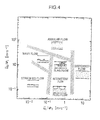
Fig. 4] Fig. 4 is a diagram showing a fluidized state of the gas-liquid two-phase flow in the horizontal direction. - [
Fig. 5] Fig. 5 is a diagram showing a fluidized state of the gas-liquid two-phase flow in the vertical direction. - [
Fig. 6] Fig. 6 is a sectional view showing a modification of the embodiment shown inFig. 1 . - [
Fig. 7] Fig. 7 is a schematic diagram showing the configuration of a vaporization system in the past. - A preferred embodiment of the present invention is explained below with reference to the drawings.
-
Fig. 1 is a schematic diagram showing an overall configuration of a vaporization system according to an embodiment of the present invention.Fig. 2 is a sectional view showing in enlargement a vaporizing tube shown inFig. 1 .Fig. 3 is a III-III line sectional view ofFig. 2 . - Referring to
Figs. 1 to 3 , avaporization system 1 includes a Stirlingengine 2, a vaporizingtube 4 attached to the Stirlingengine 2, apump 3 that supplies LNG (liquefied natural gas) to the vaporizingtube 4, and a vaporizingheater 5 that vaporizes or heats fluid led out from the vaporizingtube 4. The Stirlingengine 2 and the vaporizingtube 4 configure a vaporization apparatus in this embodiment. - The Stirling
engine 2 includes a heat exchange unit forcold energy 6 for cooling working gas (e.g., hydrogen gas or nitrogen gas) in a not-shown displacer cylinder and a heat exchange unit forhot energy 7 for heating the gas in the displacer cylinder, adisplacer piston 8 movable in the displacer cylinder, apower piston 9 movable according to compression or expansion of the gas in the displacer cylinder, and acrankshaft 10 to which thedisplacer piston 8 and thepower piston 9 are coupled. In the Stirlingengine 2, when the gas in the displacer cylinder is cooled in the heat exchange unit forcold energy 6, thepower piston 9 moves in a direction for reducing the volume of the displacer cylinder. According to the movement of thepower piston 9, thedisplacer piston 8 moves in a direction for increasing the volume on the heat exchange unit forhot energy 7. Then, according to the increase in the gas heated by the heat exchange unit forhot energy 7, thepower piston 9 moves in a direction for increasing the volume of the displacer cylinder. According to the movement, thedisplacer piston 8 moves in a direction for increasing the volume of the heat exchange unit forcold energy 6. This action is repeatedly performed, whereby power used for a rotating action of thecrankshaft 10 can be recovered. - The heat exchange unit for
cold energy 6 includes a U-shaped metal tube (an encapsulating section) 6b in which the working gas circulates and six metal plates (extending sections) 6a heat-conductibly coupled to themetal tube 6b. Each of themetal plates 6a is arranged in a standing posture. Themetal plates 6a are arranged substantially in parallel to one another in a state in which themetal plates 6a are pierced through by themetal tube 6b. Themetal plates 6a are arranged such that regions on one side (the upper side inFigs. 1 and2 ) are long compared with regions on the other side (the lower side inFigs. 1 and2 ) with respect to themetal tube 6b. - The vaporizing
tube 4 is a conduit for vaporizing the LNG. When the LNG circulates inside the vaporizingtube 4 in a state in which the vaporizingtube 4 is attached to the Stirlingengine 2, the LNG in the vaporizingtube 4 vaporizes with the heat of vaporization received from the heat exchange unit forcold energy 6. Specifically, the vaporizingtube 4 includes a lead-insection 11 for leading in the LNG from thepump 3, a vaporizing section (a heat exchange section or an auxiliary heat exchange section) 12 that cools the heat exchange unit forcold energy 6 of the Stirlingengine 2 with the LNG from the lead-insection 11, and a lead-outsection 14 for leading out the LNG from the vaporizingsection 12. The lead-insection 11, the vaporizingsection 12, and the lead-outsection 14 are coaxially arranged along an axis in the up-down direction. Consequently, a channel in the vaporizingtube 4 has a shape for circulating liquid in a direction having an upward component in the entire range from the lead-insection 11 to the lead-outsection 14. 'The shape for circulating liquid in a direction having an upward component in the entire range from the lead-insection 11 to the lead-out section 14' means the shape of the channel that can be arranged in a state not including a section where a position on an upstream side is higher than a position on a downstream side. This means that the shape is not limited to a linear shape and includes a curved shape. - The vaporizing
section 12 houses the distal end of themetal tube 6b and themetal plates 6a. Specifically, in the vaporizingsection 12, themetal plates 6a are arranged to extend along the axis of the vaporizingtube 4 in a state in which the sidewalls of themetal plates 6a are pierced through by themetal tube 6b. The vaporizingsection 12 houses themetal plates 6a in a posture in which portions on one side (the upper side inFigs. 1 and2 ) of themetal plates 6a extending longer than the other side (the lower side ofFigs. 1 and2 ) with respect to themetal tube 6b face the lead-insection 14. In other words, themetal plates 6a have a shape extending long toward the downstream side in a flowing direction of the LNG from themetal tube 6b. - The vaporizing
tube 4 according to this embodiment is attached to the Stirlingengine 2 to form a vertical ascending flow F1 (seeFig. 1 ). Specifically, the vaporizingtube 4 is attached to the Stirlingengine 2 to have a posture in which the lead-insection 11 is on the lower side and the lead-outsection 14 is on the upper side and axes thereof extend along the vertical direction in the vaporizingsection 12. When the vertical ascending flow F1 of the fluid flowing upward is formed in the vaporizingtube 4, unlike the formation of the gas-liquid two-phase flow in the horizontal direction, separated flows (a wavy flow and a stratified flow: seeFig. 4 ) are not generated. As shown inFig. 5 , a gas-liquid two-phase flow in which the liquid and the gas are mixed is formed. - Specifically, the vaporizing
tube 4 has an inner diameter dimension set to generate an air bubble flow concerning a range E1 (seeFig. 2 ) of the lead-insection 11 and a range E2 (seeFig. 2 : the heat exchange section) in which themetal tube 6b and the liquid from thepump 3 come into contact with each other, generate an air bubble flow, a slag flow, or an intermittent flow concerning a range E3 (seeFig. 2 : the auxiliary heat exchange section) further on the downstream side than themetal tube 6b in the vaporizingsection 12, and generate an intermittent flow or an annular flow concerning a range E4 of the lead-outsection 14 in a fluidized state of the gas-liquid two-phase flow in the vertical ascending flow F1 shown inFig. 5 . The air bubble flow means a flow of air bubbles dispersing in the liquid when the flow velocity of the gas is small. The intermittent flow means a flow including a slag flow in which liquid slag containing small air bubbles and gas slag alternately flow and a chum flow in which the flow velocity of the liquid increases and a large number of large and small air bubbles are present in the liquid. The annular flow means that the liquid flows along a tube wall and the gas continuously flows in a tube center. A method of setting the inner diameter dimension of the vaporizingtube 4 for forming the fluidized state is explained below. - Concerning the range E1 and the range E2, an inner diameter dimension d serving as a flow velocity parameter UL/φ2 of a liquid phase is calculated on the basis of
Formula 1 below such that the fluidized state of the gas-liquid two-phase flow shown inFig. 5 is the air bubble flow. UL is a flow velocity in the liquid phase, φ2 is a correction coefficient set to have a value of 1 when the inner diameter of the conduit is 2.54 cm, and d0 is a reference inner diameter dimension (2.54 cm). -

- In this embodiment, the inner diameter dimension of the range E1 is set smaller than the inner diameter dimension of the range E2. As a result, the flow velocity in the range E1 increases. Consequently, the density of the liquid in the gas-liquid two-phase flow in the range E1 is equal to or higher than the density of the liquid in the gas-liquid two-phase flow in the range E2. Therefore, it is possible to keep large cold energy of the gas-fluid two-phase flow in the range E1, which is a pre-stage of the range E2, i.e., the heat exchange section. As a result, it is possible to further improve the efficiency of heat exchange.
- Concerning the range E3, the flow velocity parameter UL/φ2 of the liquid phase is calculated on the basis of
Formula 1 above and a flow velocity parameter UG/φ1 of the gas phase is calculated on the basis ofFormula 2 below such that the fluidized state of the gas-liquid two-phase flow generated in the range E2 is the air bubble flow, the slag flow, or the intermittent flow. The inner diameter dimension d of the range E3 is set to satisfy these conditions. The flow velocity parameter UL/φ2 of the liquid phase concerning the air bubble flow, the slag flow, or the intermittent flow is the same asFormula 1 above. UG is the flow velocity of the gas phase, φ1 is a correction coefficient set to have a value of 1 when the inner diameter of the conduit is 2.54 cm, and θ is an angle (in this embodiment, 90°) formed by the flowing direction of the LNG and the horizontal direction.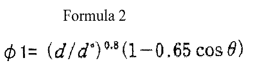
- Concerning the range E4, the inner diameter dimension d is set such that the fluidized state of the gas-liquid two-phase flow generated in the range E3 is the intermittent flow or the annular flow. Specifically, when the intermittent flow is formed, the flow velocity parameter UL/φ2 of the liquid phase is calculated on the basis of
Formula 1 above, the flow velocity parameter UG/φ1 of the gas phase is calculated on the basis ofFormula 2 above, and the inner dimension parameter d of the range E4 is set to satisfy these conditions. - On the other hand, when the annular flow is formed, the flow velocity parameter UL/φ2 of the liquid phase is calculated, the flow velocity parameter UG/φ1 of the gas phase is calculated on the basis of
Formula 3 below, and the inner dimension parameter d of the range E4 is set to satisfy these conditions. φ2 in the formation of the annular flow is 1. Therefore, a flow velocity parameter of the liquid phase depends on the flow velocity UL. ρG is the density of the gas, ρG 0 is 1.3 kg×m-3, Δρ0 is (ρL 0-ρG 0), Δρ is (ρL-ρG), σ0 is 0.07 N×m-1, and σ is surface tension.
- The operation of the
vaporization system 1 is explained below. - First, as explained above, the vaporizing
tube 4 that covers the heat exchange unit forcold energy 6 of theStirling engine 2 and is capable of forming a vertical ascending flow of the liquid flowing from the bottom to the top of the heat exchange unit forcold energy 6 is prepared (a preparing step). - Subsequently, the
pump 3 is provided below the vaporizingtube 4 and the vaporizingheater 5 is provided above the vaporizingtube 4. The LNG is ejected from thepump 3, whereby the vertical ascending flow F1 of the LNG led in from below (the lead-in section 11) the vaporizingtube 4 and led out from above (the lead-out section 14) the vaporizingtube 4 is formed. - Specifically, the LNG changes to an air bubble flow in the lead-in section 11 (the range E1) to be led into the vaporizing
section 12. The liquid not vaporized yet in the LNG led into the vaporizingsection 12 in the state of the air bubble flow comes into contact with themetal tube 6b in the range E2 and receives the heat of vaporization from themetal tube 6b to thereby vaporize (a vaporizing step). Consequently, in the range E3 located further on the downstream side than the range E2, as an air bubble flow same as that in the range E2 or a slag flow or an intermittent flow having a less liquid phase compared with the range E2 is formed. In the range E3, the liquid not vaporized yet in the gas-liquid two-phase flow led in from the range E2 comes into contact with themetal plates 6a and receives the heat of vaporization from themetal plates 6a to thereby vaporize. The gas-liquid two-phase flow from the range E3 is led out from the lead-outsection 14 in a state in which the gas-liquid two-phase flow is changed to an intermittent flow or an annular flow in the range E4. - Further, in this embodiment, the vaporizing
heater 5 is provided on the lead-outsection 14 and the gas-liquid two-phase flow led out from the lead-outsection 14 is guided to the vaporizingheater 5 in the form of the ascending flow F1 (a guiding step). Therefore, the liquid not vaporized by the heat exchange unit forcold energy 6 of theStirling engine 2 is guided to the vaporizingheater 5 together with the liquid already vaporized and is vaporized in the vaporizingheater 5. On the other hand, the gas is heated in the vaporizingheater 5. - As explained above, according to the embodiment, since the vertical ascending flow F1 is formed, it is possible to suppress occurrence of separated flows of the liquid and the gas in the vaporizing
tube 4. Therefore, even when the flow velocity of the liquid is low, it is possible to maintain the gas-liquid two-phase flow in which the gas and the liquid are mixed without a gas-liquid interface being separated. A reason for the above is explained with reference toFigs. 4 and5 . InFigs. 4 and5 , the abscissa indicates a parameter concerning the velocity of the liquid and the ordinate indicates a parameter concerning the velocity of the gas. As indicated byFig. 4 showing the fluidized state of the gas-liquid two-phase flow in the horizontal direction, in the gas-liquid two-phase flow in the horizontal direction, a state in which the gas-liquid interface is separated (a wavy flow and a stratified flow) occurs according to a decrease in the flow velocity of the fluid. On the other hand, as in the embodiment, in the gas-liquid two-phase flow in the vertical direction (an ascending flow), the gas-liquid interface is not separated even if the flow velocity of the liquid decrease as shown inFig. 5 . It is possible to maintain the state of the slag flow or the air bubble flow. Therefore, in the gas-liquid two-phase flow in the vertical direction, it is possible to efficiently circulate the liquid and the gas already vaporized. - In the embodiment, 'an angle set in advance for suppressing occurrence of separated flows of the liquid and gas in the conduit' means an angle θ that satisfies the condition of
Formula 4 below. θ is an angle formed by the flowing direction of the ascending flow and the horizontal direction, d is the inner diameter (the diameter) of the conduit, and 1 is a channel length of the gas-liquid two-phase flow in the conduit. - In the embodiment, the ascending flow is formed vertically. However, the ascending flow is not limited to be vertically formed. It is possible to suppress the occurrence of the separated flows if the flowing direction of the ascending flow is adjusted to be fit within a range of the angle θ of
Formula 4 below.
- In the embodiment, after the occurrence of the separated flows is suppressed as explained above, the liquid is supplied from the
pump 3 at a flow velocity at which the gas-liquid two-phase flow is formed in the vaporizingtube 4. Therefore, it is possible to effectively vaporize the liquid contained in the gas-liquid two-phase flow with the heat of vaporization received from the heat exchange unit forcold energy 6 of theStirling engine 2 while effectively circulating the gas-liquid two-phase flow in the state in which the gas and the liquid are mixed. - In the embodiment, after the occurrence of the separated flows is suppressed as explained above, the liquid is supplied from the
pump 3 at the flow velocity at which the gas-liquid two-phase flow is formed in the vaporizingtube 4. Therefore, it is possible to effectively vaporize the liquid contained in the gas-liquid two-phase flow with the heat of vaporization received from the heat exchange unit forcold energy 6 of theStirling engine 2 while effectively circulating the gas-liquid two-phase flow in the state in which the gas and the liquid are mixed. - Therefore, according to the embodiment, it is possible to perform vaporization of the remaining liquid while collecting the target gas by circulating the liquid and the gas as the gas-liquid two-phase flow of the vertical ascending flow F1. Therefore, it is possible to obtain the target gas at high efficiency without requiring a complicated process and complicated equipment. In particular, when liquid in which a plurality of components having different boiling points are mixed such as the LNG is supplied to the vaporizing
tube 4, low-boiling point components can be easily vaporized by the heat of vaporization from theStirling engine 2. On the other hand, high-boiling point components may be unable to be sufficiently vaporized by the heat of vaporization from theStirling engine 2. However, by adopting the vaporization system according to the embodiment, it is possible to effectively guide low-boiling point components (gas) already vaporized and high-boiling point components (liquid) not vaporized yet to the vaporizingheater 5. Therefore, it is possible to vaporize the high-boiling components with the vaporizingheater 5. Consequently, it is possible to obtain target natural gas at high efficiency. - The embodiment is a configuration for forming the air bubble flow in the range E2 (the heat exchange section) and forming the air bubble flow, the slag flow, or the intermittent flow in the range E3 (the auxiliary heat exchange section). With this configuration, it is possible to circulate the liquid at a relatively low velocity and uniformly. Therefore, it is possible to surely bring the liquid and the heat exchange unit for
cold energy 6 into contact with each other. Consequently, it is possible to realize efficiency of vaporization. - The embodiment is a configuration in which the inner diameter dimension of the lead-in
section 11 is set smaller than the inner diameter dimension of the vaporizingsection 12. With this configuration, it is possible to set the density of the liquid in the lead-insection 11 larger than the density of the liquid in the vaporizingsection 12. Therefore, it is possible to maintain a state in which a lot of cold energy is retained at a stage before the liquid is guided to the vaporizingsection 12. As a result, it is possible to more effectively perform vaporization in the vaporizingsection 12. - In the embodiment, the heat exchange unit for
cold energy 6 includes the metal tube (the encapsulating section) 6b and the plurality of metal plates (the extending sections) 6a. The gas-liquid two-phase flow is formed in the range E2 (the heat exchanging section) and the range E3 (the auxiliary heat exchanging section). With this form, it is possible to effectively vaporize the liquid in the range E3 in addition to the range E2. - If the liquid and the gas are led from the lead-out
section 14 to the vaporizingheater 5 while being kept in the state of the ascending flow F1 as in the embodiment, it is possible to suppress the occurrence of the separate flows between the lead-outsection 14 and the vaporizingheater 5 as well. Therefore, it is possible to vaporize the liquid, which is not vaporized by theStirling engine 2, with the vaporizingheater 5 and obtain the target gas at high efficiency. - In the embodiment, the vaporizing
tube 4 including the linear channel in which the lead-insection 11, the vaporizingsection 12, and the lead-outsection 14 are coaxially arranged is explained. However, the channel in the vaporizingtube 4 is not limited to the linear shape and may be, for example, a curved shape as long as the shape is the shape of the channel that can be arranged in a state in which the channel does not have a section where the position on the upstream side of the channel is higher than the position on the downstream side. - In the embodiment, the
cylindrical vaporizing tube 4 is explained. However, the sectional shape of the vaporizing tube is not limited to a circle and may be, for example, a rectangle as shown inFig. 6 . In the vaporizingtube 22, a representative diameter in the case in which a cylindrical container having a sectional area equal to the sectional area of the vaporizingtube 22 is assumed can be adopted as the inner diameter dimension d. This is because, since the sectional area is equal irrespective of the shape of the sectional area, a state of the gas-liquid two-phase flow is approximated. - The diameter dimension of the vaporizing
tube 4 in the case in which LNG having 0.3 MPaG and -160°C is supplied at a flow rate of 1 t/h is explained below. It is assumed that the LNG supplied to the vaporizingtube 4 is heated to -133°C by heat exchange with the heat exchange unit forcold energy 6 of theStirling engine 2. - In this example, an air bubble flow is generated concerning the range E1. Therefore, a value of the flow velocity parameter UL/φ2 is required to be smaller than 3 (see
Fig. 5 ). If the diameter dimension d in the range E1 is set to 40 mm, φ2 (=d/d°) is 1.575. Therefore, the flow velocity UL is required to be smaller than 4.724 m/sec. - It is examined whether the condition is satisfied. The density of the LNG at 0.3 MPaG and -160°C is 460 kg/m3. Therefore, the flow rate of the LNG in the range E1 is 0.604x 10⁻³ m3/sec. Since the diameter dimension d of the range E1 is 40 mm, the flow velocity UL is about 0.5 m/sec. Therefore, when the diameter dimension of the range E1 is set to 40 mm, the condition (the flow velocity UL < 4.724 m/sec) is satisfied.
- In this example, an air bubble flow is generated concerning the range E2. Therefore, a value of the flow velocity parameter UL/φ2 is required to be smaller than 3 (see
Fig. 5 ). If the diameter dimension d in the range E2 is set to 500 mm, φ2 (see Formula 1) is 19.69. Therefore, the flow velocity UL is required to be smaller than 59.06 m/sec. - It is examined whether the condition is satisfied. The density of the LNG at 0.3 MPaG and -160°C is 460 kg/m3. Therefore, the flow rate of the LNG in the range E2 is 0.604×10⁻³ m3/sec. Since the diameter dimension d of the range E2 is 500 mm, the flow velocity UL is about 3.1×10⁻³ m/sec. Therefore, when the diameter dimension of the range E2 is set to 500 mm, the condition (the flow velocity UL, < 59.06 m/sec) is satisfied.
- In this example, an air bubble flow, a slag flow, or an intermittent flow is generated concerning the range E3. Therefore, a value of the flow velocity parameter UG/φ1 is required to be smaller than 1.0 (see
Fig. 5 ). If the diameter dimension d in the range E3 is set to 500 mm, φ1 (see Formula 2: θ=90°) is 10.85. Therefore, the flow velocity UG is required to be smaller than 10.85 m/sec. - It is examined whether the condition is satisfied. From a relation with the density of the LNG at 0.3 MPaG and -133°C, the flow rate of the LNG in the range E3 is 0.058 m3/sec. Since the diameter dimension d of the range E3 is 500 mm, the flow velocity UG is about 0.3 m/sec.
- In this example, a slag flow, an intermittent flow, or an annular flow is generated concerning the range E4. Therefore, a value of the flow velocity parameter Uo/φ1 is required to be larger than 0.1 (
Fig. 5 ). If the diameter dimension d in the range E4 is set to 120 mm, φ1 (see Formula 4: θ=90°) is 3.46. Therefore, the flow velocity UG is required to be larger than 0.346 m/sec. - It is examined whether the condition is satisfied. From a relation with the density of the LNG at 0.3 MPaG and -133°C, the flow rate of the LNG in the range E4 is 0.058 m3/sec. Since the diameter dimension d of the range E4 is 120 mm, the flow velocity UG is about 5 m/sec. Therefore, when the diameter dimension of the range E4 is set to 120 mm, the condition (the flow velocity UG > 0.346 m/sec) is satisfied.
- The embodiment explained above is summarized as explained below.
- A vaporization method according to the embodiment is a method of vaporizing liquid using a Stirling engine including a heat exchange unit for cold energy, the method including: a preparing step of preparing a conduit that covers at least a part of the heat exchange unit for cold energy of the Stirling engine and is capable of forming an ascending flow of the liquid flowing from a bottom to a top of the heat exchange unit for cold energy; and a vaporizing step of feeding the liquid in the conduit to thereby form the ascending flow and bringing the liquid into contact with the Stirling engine to vaporize the liquid. In the preparing step, a flowing direction of the ascending flow is adjusted to be an angle set in advance for suppressing occurrence of separated flows of the liquid and gas in the conduit. In the vaporizing step, the liquid is fed at a flow velocity at which a gas-liquid two-phase flow in which the liquid and the gas are mixed is formed in the conduit.
- With this configuration, since the flowing direction of the ascending flow is adjusted to the predetermined angle, it is possible to suppress the occurrence of the separated flows of the liquid and the gas in the conduit. Therefore, even when the flow velocity of the liquid is low, it is possible to maintain the gas-liquid two-phase flow in which the gas and the liquid are mixed without a gas-liquid interface being separated.
- In the vaporizing step, the liquid is fed at a flow velocity at which an intermittent flow or an air bubble flow is formed in a heat exchange section of the conduit in which the heat exchange unit for cold energy and the liquid come into contact with each other.
- With this configuration, it is possible to more effectively bring the liquid and the heat exchange unit for cold energy into contact with each other.
- In the preparing step, the conduit is prepared including a heat exchange section in which the heat exchange unit for cold energy and the liquid come into contact with each other, and a lead-in section that has a sectional area smaller than a sectional area of a channel of the heat exchange section and that leads the liquid into the heat exchange section.
- With this configuration, since the sectional area of the channel in the lead-in section is set smaller than the sectional area of the channel in the heat exchange section, it is possible to set the density of the liquid in the lead-in section larger than the density of the liquid in the heat exchange section. Therefore, it is possible to maintain a state in which a lot of cold energy is retained at a stage before the liquid is guided to the heat exchange section. As a result, it is possible to more effectively perform vaporization in the heat exchange section.
- The heat exchange unit for cold energy includes an encapsulating section in which working gas of the Stirling engine is encapsulated, and a plurality of extending sections heat-conductibly coupled to the encapsulating section and extending in a flowing direction of the liquid from the encapsulating section. In the preparing step, the conduit is prepared including a heat exchange section which covers at least a part of the encapsulating section and in which the encapsulating section and the liquid come into contact with each other, and an auxiliary heat exchange section which covers the extending sections and in which the extending sections and the liquid come into contact with each other. In the vaporizing step, the liquid is fed at a flow velocity at which the gas-liquid two-phase flow is formed in the heat exchange section and the auxiliary heat exchange section.
- With this configuration, it is possible to prepare the conduit including not only the heat exchange section but also the auxiliary heat exchange section as an area for vaporizing the liquid. Therefore, it is possible to more effectively perform vaporization by vaporizing the liquid in a large area.
- The vaporization method according to the embodiment further includes a guiding step of guiding the liquid led out in the form of the ascending flow from the conduit to a vaporizing heater for vaporizing the liquid and heating the gas.
- With this configuration, since the liquid and the gas led out from the conduit is guided while being kept in the state of the ascending flow, it is possible to suppress the occurrence of the separated flows between the conduit and the vaporizing heater as well. Therefore, it is possible to vaporize the liquid, which is not vaporized by the Stirling engine, with the vaporizing heater and obtain the target gas at high efficiency.
- A vaporization apparatus according to the embodiment includes a Stirling engine including a heat exchange unit for cold energy, and a vaporizing tube which is attached to the Stirling engine while covering the heat exchange unit for cold energy and in which liquid circulates so as to come into contact with the heat exchange unit for cold energy. The vaporizing tube is attached to the Stirling engine at an angle set in advance. The angle set in advance is an angle at which an ascending flow of the liquid flowing from a bottom to a top of the heat exchange unit for cold energy can be formed and at which a flowing direction of the ascending flow is adjusted to suppress occurrence of separated flows of the liquid and gas in the vaporizing tube.
- With this configuration, it is possible to suppress the occurrence of the separated flows in the vaporizing tube. Therefore, as explained above, even when the flow velocity of the liquid is low, it is possible to maintain the gas-liquid two-phase flow in which the gas and the liquid are mixed without a gas-liquid interface being separated. With the configuration, the liquid in the vaporizing tube comes into contact with the heat exchange unit for cold energy to vaporize. Therefore, it is possible to obtain the target gas at high efficiency.
- Specifically, the vaporizing tube includes a heat exchange section that circulates the liquid such that the liquid comes into contact with the heat exchange unit for cold energy, a lead-in section for leading the liquid into the heat exchange section, and a lead-out section for leading out gas vaporized in the heat exchange section and the liquid from the heat exchange section. A channel in the vaporizing tube has a shape for circulating the liquid in a direction having an upward component in the entire range from the lead-in section to the lead-out section.
- The vaporizing tube includes a heat exchange section that circulates the liquid such that the liquid comes into contact with the heat exchange unit for cold energy, and a lead-in section for leading the liquid into the heat exchange section. A sectional area of a channel in the led-in section is set smaller than a sectional area of a channel in the heat exchange section.
- With this configuration, since the sectional area of the channel in the lead-in section is set smaller than the sectional area of the channel in the heat exchange section, it is possible to set the density of the liquid in the lead-in section higher than the density of the liquid in the heat exchange section. Therefore, it is possible to maintain a state in which a lot of cold energy is retained at a stage before the liquid is guided to the heat exchange section. As a result, it is possible to more effectively perform vaporization in the heat exchange section.
- The heat exchange unit for cold energy includes an encapsulating section in which working gas of the Stirling engine is encapsulated, and a plurality of extending sections heat-conductibly coupled to the encapsulating section and extending upward from the encapsulating section. The vaporizing tube includes a heat exchange section which covers at least a part of the encapsulating section and in which the encapsulating section and the liquid come into contact with each other, and an auxiliary heat exchange section which covers the extending sections and in which the extending sections and the liquid come into contact with each other.
- With this configuration, since the vaporizing tube includes not only the heat exchange section but also the auxiliary heat exchange section, it is possible to more effectively perform vaporization in a large area.
- A vaporization system according to the embodiment includes the vaporization apparatus, a supply source capable of supplying liquid to the vaporizing tube of the vaporization apparatus, and a vaporizing heater for vaporizing the liquid led out from the vaporizing tube and heating gas led out from the vaporizing tube. The supply source supplies the liquid to the vaporizing tube at a flow velocity at which a gas-liquid two-phase flow in which the liquid and the gas are mixed is formed in the vaporizing tube.
- With this configuration, it is possible to form the gas-liquid two-phase flow in which the liquid and the gas are mixed in the vaporizing tube. Therefore, the liquid contained in the gas-liquid two-phase flow is vaporized by the heat exchange unit for cold energy of the Stirling engine and the liquid not vaporized by the heat exchange unit for cold energy and led out as an ascending flow from the vaporizing tube is vaporized by the vaporizing heater. Therefore, it is possible to obtain target gas at high efficiency without requiring a complicated process and a complicated configuration.
- The vaporizing tube includes a heat exchange section that circulates the liquid such that the liquid comes into contact with the heat exchange unit for cold energy. The supply source supplies the liquid to the vaporizing tube at a flow velocity at which an intermittent flow or an air bubble flow is formed in the heat exchange section.
- With this configuration, it is possible to effectively bring the liquid contained in the gas-liquid two-phase flow and the heat exchange unit for cold energy of the Stirling engine into contact with each other by forming the intermittent flow or the air bubble flow in which the liquid circulates uniformly at a relatively low flow velocity. Therefore, it is possible to further improve efficiency of vaporization by the Stirling engine.
- The vaporizing heater is provided above the vaporizing tube and receives the liquid and the gas led out from the vaporizing tube in the form of the ascending flow.
- With this configuration, it is possible to surely guide the liquid and the gas to the vaporizing heater while suppressing occurrence of separated flows by forming the ascending flow between the vaporizing tube and the vaporizing heater as well. Therefore, it is possible to surely vaporize the liquid contained in the gas-liquid two-phase flow related to the ascending flow with the vaporizing heater. Therefore, with the configuration, it is possible to obtain target gas at higher efficiency.
- As explained above, the vaporization method, the vaporization apparatus used for the vaporization method, and the vaporization system provided with the vaporization apparatus according to the present invention are useful for vaporizing the liquid while recovering power using the Stirling engine and is suitable for suppressing occurrence of separated flows of the liquid and the gas in the conduit of the vaporizing tube and maintaining the gas-liquid two-phase flow in which the gas and the liquid are mixed.
Claims (12)
- A method of vaporizing liquid using a Stirling engine including a heat exchange unit for cold energy, the method comprising:a preparing step of preparing a conduit that covers at least a part of the heat exchange unit for cold energy of the Stirling engine and is capable of forming an ascending flow of the liquid flowing from a bottom to a top of the heat exchange unit for cold energy; anda vaporizing step of feeding the liquid in the conduit to thereby form the ascending flow and bringing the liquid into contact with the Stirling engine to vaporize the liquid, whereinin the preparing step, a flowing direction of the ascending flow is adjusted to be an angle set in advance for suppressing occurrence of separated flows of the liquid and gas in the conduit, andin the vaporizing step, the liquid is fed at a flow velocity at which a gas-liquid two-phase flow in which the liquid and the gas are mixed is formed in the conduit.
- The vaporization method according to claim 1, wherein, in the vaporizing step, the liquid is fed at a flow velocity at which an intermittent flow or an air bubble flow is formed in a heat exchange section of the conduit in which the heat exchange unit for cold energy and the liquid come into contact with each other.
- The vaporization method according to claim 1, wherein, in the preparing step, the conduit is prepared including a heat exchange section in which the heat exchange unit for cold energy and the liquid come into contact with each other, and a lead-in section that has a sectional area smaller than a sectional area of a channel of the heat exchange section and that leads the liquid into the heat exchange section.
- The vaporization method according to claim 1, wherein
the heat exchange unit for cold energy includes an encapsulating section in which working gas of the Stirling engine is encapsulated, and a plurality of extending sections heat-conductibly coupled to the encapsulating section and extending in a flowing direction of the liquid from the encapsulating section,
in the preparing step, the conduit is prepared including a heat exchange section which covers at least a part of the encapsulating section and in which the encapsulating section and the liquid come into contact with each other, and an auxiliary heat exchange section which covers the extending sections and in which the extending sections and the liquid come into contact with each other, and
in the vaporizing step, the liquid is fed at a flow velocity at which the gas-liquid two-phase flow is formed in the heat exchange section and the auxiliary heat exchange section. - The vaporization method according to any one of claims 1 to 4, further comprising a guiding step of guiding the liquid led out in the form of the ascending flow from the conduit to a vaporizing heater for vaporizing the liquid and heating the gas.
- A vaporization apparatus comprising:a Stirling engine including a heat exchange unit for cold energy; anda vaporizing tube which is attached to the Stirling engine while covering the heat exchange unit for cold energy and in which liquid circulates so as to come into contact with the heat exchange unit for cold energy, whereinthe vaporizing tube is attached to the Stirling engine at an angle set in advance, andthe angle set in advance is an angle at which an ascending flow of the liquid flowing from a bottom to a top of the heat exchange unit for cold energy can be formed and at which a flowing direction of the ascending flow is adjusted to suppress occurrence of separated flows of the liquid and gas in the vaporizing tube.
- The vaporization apparatus according to claim 6, wherein
the vaporizing tube includes a heat exchange section that circulates the liquid such that the liquid comes into contact with the heat exchange unit for cold energy, a lead-in section for leading the liquid into the heat exchange section, and a lead-out section for leading out gas vaporized in the heat exchange section and the liquid from the heat exchange section, and
a channel in the vaporizing tube has a shape for circulating the liquid in a direction having an upward component in an entire range from the lead-in section to the lead-out section. - The vaporization apparatus according to claim 6, wherein
the vaporizing tube includes a heat exchange section that circulates the liquid such that the liquid comes into contact with the heat exchange unit for cold energy, and a lead-in section for leading the liquid into the heat exchange section, and
a sectional area of a channel in the led-in section is set smaller than a sectional area of a channel in the heat exchange section. - The vaporization apparatus according to claim 6, wherein
the heat exchange unit for cold energy includes an encapsulating section in which working gas of the Stirling engine is encapsulated, and a plurality of extending sections heat-conductibly coupled to the encapsulating section and extending upward from the encapsulating section, and
the vaporizing tube includes a heat exchange section which covers at least a part of the encapsulating section and in which the encapsulating section and the liquid come into contact with each other, and an auxiliary heat exchange section which covers the extending sections and in which the extending sections and the liquid come into contact with each other. - A vaporization system comprising:the vaporization apparatus according to any one of claims 6 to 9;a supply source capable of supplying liquid to the vaporizing tube of the vaporization apparatus; anda vaporizing heater for vaporizing the liquid led out from the vaporizing tube and heating gas led out from the vaporizing tube, whereinthe supply source supplies the liquid to the vaporizing tube at a flow velocity at which a gas-liquid two-phase flow in which the liquid and the gas are mixed is formed in the vaporizing tube.
- The vaporization system according to claim 10, wherein
the vaporizing tube includes a heat exchange section that circulates the liquid such that the liquid comes into contact with the heat exchange unit for cold energy, and
the supply source supplies the liquid to the vaporizing tube at a flow velocity at which an intermittent flow or an air bubble flow is formed in the heat exchange section. - The vaporization system according to claim 1 l, wherein the vaporizing heater is provided above the vaporizing tube and receives the liquid and the gas led out from the vaporizing tube in the form of the ascending flow.
Applications Claiming Priority (2)
| Application Number | Priority Date | Filing Date | Title |
|---|---|---|---|
| JP2010131650A JP5523935B2 (en) | 2010-06-09 | 2010-06-09 | Vaporization method, vaporization apparatus used therefor, and vaporization system provided with the same |
| PCT/JP2011/002972 WO2011155146A1 (en) | 2010-06-09 | 2011-05-27 | Vaporization method and vaporization apparatus used for vaporization method, and vaporization system provided with vaporization apparatus |
Publications (2)
| Publication Number | Publication Date |
|---|---|
| EP2573374A1 true EP2573374A1 (en) | 2013-03-27 |
| EP2573374A4 EP2573374A4 (en) | 2015-12-30 |
Family
ID=45097767
Family Applications (1)
| Application Number | Title | Priority Date | Filing Date |
|---|---|---|---|
| EP11792108.0A Withdrawn EP2573374A4 (en) | 2010-06-09 | 2011-05-27 | VAPORIZATION METHOD AND SPRAY APPARATUS USED FOR THIS METHOD, AND VAPORIZATION SYSTEM PROVIDED WITH SAID APPARATUS |
Country Status (4)
| Country | Link |
|---|---|
| US (1) | US9371745B2 (en) |
| EP (1) | EP2573374A4 (en) |
| JP (1) | JP5523935B2 (en) |
| WO (1) | WO2011155146A1 (en) |
Families Citing this family (4)
| Publication number | Priority date | Publication date | Assignee | Title |
|---|---|---|---|---|
| JP5466088B2 (en) * | 2010-06-09 | 2014-04-09 | 株式会社神戸製鋼所 | Power recovery system |
| TWI654666B (en) | 2014-01-27 | 2019-03-21 | Veeco Instruments, Inc. | Wafer carrier with compound radius accommodating cavity for chemical vapor deposition system |
| US9627239B2 (en) | 2015-05-29 | 2017-04-18 | Veeco Instruments Inc. | Wafer surface 3-D topography mapping based on in-situ tilt measurements in chemical vapor deposition systems |
| WO2017048192A1 (en) * | 2015-09-15 | 2017-03-23 | Nanyang Technological University | Power generation system and method |
Family Cites Families (27)
| Publication number | Priority date | Publication date | Assignee | Title |
|---|---|---|---|---|
| US4300625A (en) * | 1975-01-21 | 1981-11-17 | Mikhailov Gerold M | Preventing deposition on the inner surfaces of heat exchange apparatus |
| JPS5314258A (en) * | 1976-07-24 | 1978-02-08 | Tokyo Gas Co Ltd | Stirring engine |
| JPS54101539A (en) * | 1978-01-27 | 1979-08-10 | Kobe Steel Ltd | Heat exchange pipe for use with water-sprinkling type, panel-shaped, liquefied natural gas evaporator and combination of such pipes and their manufacturing method |
| US4367625A (en) * | 1981-03-23 | 1983-01-11 | Mechanical Technology Incorporated | Stirling engine with parallel flow heat exchangers |
| US4462212A (en) * | 1981-12-30 | 1984-07-31 | Knoeoes Stellan | Unitary heat engine/heat pump system |
| GB2116686B (en) * | 1982-02-18 | 1985-01-30 | Tokyo Shibaura Electric Co | Heat exchangers installed in fluidized beds |
| JPS5924152A (en) | 1982-07-30 | 1984-02-07 | アイシン精機株式会社 | Cooler made of aluminum for stirling-engine |
| JPH0344065A (en) * | 1989-07-12 | 1991-02-25 | Hitachi Ltd | Semiconductor cooling method |
| JPH05164482A (en) * | 1991-12-12 | 1993-06-29 | Kobe Steel Ltd | Liquefied natural gas vaporizer |
| US5406807A (en) | 1992-06-17 | 1995-04-18 | Hitachi, Ltd. | Apparatus for cooling semiconductor device and computer having the same |
| JPH06104357A (en) * | 1992-08-27 | 1994-04-15 | Hitachi Ltd | Semiconductor cooling device |
| JPH0719008A (en) * | 1993-06-30 | 1995-01-20 | Aisin Seiki Co Ltd | Stirling engine heating device |
| US5394700A (en) * | 1993-10-12 | 1995-03-07 | Steele; Ronald J. | Stirling engine with ganged cylinders and counter rotational operating capability |
| JPH1122550A (en) * | 1997-07-03 | 1999-01-26 | Morikawa Sangyo Kk | Sterling engine which can use lng as cooler coolant |
| KR100233198B1 (en) * | 1997-07-04 | 1999-12-01 | 윤종용 | Vibration Absorption Pump System of Stirling Refrigerator |
| TW432192B (en) * | 1998-03-27 | 2001-05-01 | Exxon Production Research Co | Producing power from pressurized liquefied natural gas |
| US6513326B1 (en) * | 2001-03-05 | 2003-02-04 | Joseph P. Maceda | Stirling engine having platelet heat exchanging elements |
| JP4174619B2 (en) * | 2001-10-11 | 2008-11-05 | 株式会社レーベン販売 | External combustion engine driven by heat pump |
| GB0130378D0 (en) * | 2001-12-19 | 2002-02-06 | Bg Intellectual Pty Ltd | A domestic combined heat and power unit |
| US20070193266A1 (en) * | 2006-02-17 | 2007-08-23 | Stirling Cycles, Inc. | Multi-cylinder free piston stirling engine |
| US20070214805A1 (en) * | 2006-03-15 | 2007-09-20 | Macmillan Adrian Armstrong | Onboard Regasification of LNG Using Ambient Air |
| US20070214804A1 (en) * | 2006-03-15 | 2007-09-20 | Robert John Hannan | Onboard Regasification of LNG |
| US20110041492A1 (en) * | 2006-05-10 | 2011-02-24 | Daniel Maguire | Stirling engine with thermoelectric control |
| JP4723468B2 (en) * | 2006-12-25 | 2011-07-13 | 株式会社神戸製鋼所 | Liquefied gas vaporization system and control method thereof |
| US20080250795A1 (en) * | 2007-04-16 | 2008-10-16 | Conocophillips Company | Air Vaporizer and Its Use in Base-Load LNG Regasification Plant |
| JP4917008B2 (en) * | 2007-12-12 | 2012-04-18 | 株式会社神戸製鋼所 | Liquefied gas vaporization system |
| US8640454B1 (en) * | 2010-02-27 | 2014-02-04 | Jonathan P. Nord | Lower costs and increased power density in stirling cycle machines |
-
2010
- 2010-06-09 JP JP2010131650A patent/JP5523935B2/en active Active
-
2011
- 2011-05-27 WO PCT/JP2011/002972 patent/WO2011155146A1/en not_active Ceased
- 2011-05-27 US US13/702,297 patent/US9371745B2/en not_active Expired - Fee Related
- 2011-05-27 EP EP11792108.0A patent/EP2573374A4/en not_active Withdrawn
Also Published As
| Publication number | Publication date |
|---|---|
| WO2011155146A1 (en) | 2011-12-15 |
| US9371745B2 (en) | 2016-06-21 |
| JP2011256776A (en) | 2011-12-22 |
| EP2573374A4 (en) | 2015-12-30 |
| JP5523935B2 (en) | 2014-06-18 |
| US20130081390A1 (en) | 2013-04-04 |
Similar Documents
| Publication | Publication Date | Title |
|---|---|---|
| US9371745B2 (en) | Vaporization method and vaporization apparatus used for vaporization method, and vaporization system provided with vaporization apparatus | |
| EP2455154A1 (en) | Carbon dioxide recovery apparatus and carbon dioxide recovery method | |
| US20130193786A1 (en) | Sr motor alternative cooling device and method | |
| EP2781250B1 (en) | Apparatus and method for carbon dioxide recovery | |
| EP3248718A1 (en) | 3d additive manufacturing device, control method for 3d additive manufacturing device, control program for 3d additive manufacturing device, and jig | |
| JP6675865B2 (en) | Liquid material vaporizer | |
| EP1793422A3 (en) | System and method of enhanced boiling heat transfer using pin fins | |
| EP3020493B1 (en) | Nanoparticle production method, production device and automatic production device | |
| JP2013088051A (en) | Self-excited vibration heat pipe | |
| JP4917008B2 (en) | Liquefied gas vaporization system | |
| US20180161911A1 (en) | Angled plasma cutting torch | |
| WO2008139146A2 (en) | Method and apparatus for controlling gaseous hydrolysis production | |
| CN210601546U (en) | Real-time vaporizing device capable of accurately controlling steam flow and steam temperature | |
| US9988964B2 (en) | Ebullient cooling device | |
| EP3805668A1 (en) | Fluid temperature adjustment device | |
| JP2011190955A (en) | Method and device for manufacturing heat pipe | |
| CN208960942U (en) | A kind of evaporating and cooling electromagnetic blender of composite condensation | |
| US10151540B2 (en) | Reboiler with void within the heat transfer tube group | |
| EP2573373A1 (en) | Power recovery system | |
| US20040011061A1 (en) | Device and process for the cryogenic filling of aerosol product batches | |
| JP5309684B2 (en) | Work cooling method and work cooling device | |
| US10101416B2 (en) | Method and device for controlling the temperature of a flow of fluid intended to be used by an NMR analysis probe, and corresponding NMR analysis system | |
| US7901639B2 (en) | Reaction apparatus | |
| CN109128066A (en) | A kind of evaporating and cooling electromagnetic blender of composite condensation | |
| WO2012082247A1 (en) | Apparatus, process and system for delivering fluid to a distillation column or reactor |
Legal Events
| Date | Code | Title | Description |
|---|---|---|---|
| PUAI | Public reference made under article 153(3) epc to a published international application that has entered the european phase |
Free format text: ORIGINAL CODE: 0009012 |
|
| 17P | Request for examination filed |
Effective date: 20121218 |
|
| AK | Designated contracting states |
Kind code of ref document: A1 Designated state(s): AL AT BE BG CH CY CZ DE DK EE ES FI FR GB GR HR HU IE IS IT LI LT LU LV MC MK MT NL NO PL PT RO RS SE SI SK SM TR |
|
| DAX | Request for extension of the european patent (deleted) | ||
| RA4 | Supplementary search report drawn up and despatched (corrected) |
Effective date: 20151130 |
|
| RIC1 | Information provided on ipc code assigned before grant |
Ipc: F28D 21/00 20060101ALN20151124BHEP Ipc: F02G 1/055 20060101AFI20151124BHEP Ipc: F17C 9/02 20060101ALI20151124BHEP |
|
| 17Q | First examination report despatched |
Effective date: 20190320 |
|
| STAA | Information on the status of an ep patent application or granted ep patent |
Free format text: STATUS: THE APPLICATION HAS BEEN WITHDRAWN |
|
| 18W | Application withdrawn |
Effective date: 20190705 |