EP2573330A2 - Compliant mounting of an axial face seal assembly - Google Patents
Compliant mounting of an axial face seal assembly Download PDFInfo
- Publication number
- EP2573330A2 EP2573330A2 EP12185182A EP12185182A EP2573330A2 EP 2573330 A2 EP2573330 A2 EP 2573330A2 EP 12185182 A EP12185182 A EP 12185182A EP 12185182 A EP12185182 A EP 12185182A EP 2573330 A2 EP2573330 A2 EP 2573330A2
- Authority
- EP
- European Patent Office
- Prior art keywords
- spring
- carrier
- seal assembly
- face seal
- axial face
- Prior art date
- Legal status (The legal status is an assumption and is not a legal conclusion. Google has not performed a legal analysis and makes no representation as to the accuracy of the status listed.)
- Withdrawn
Links
Images


Classifications
-
- F—MECHANICAL ENGINEERING; LIGHTING; HEATING; WEAPONS; BLASTING
- F01—MACHINES OR ENGINES IN GENERAL; ENGINE PLANTS IN GENERAL; STEAM ENGINES
- F01D—NON-POSITIVE DISPLACEMENT MACHINES OR ENGINES, e.g. STEAM TURBINES
- F01D11/00—Preventing or minimising internal leakage of working-fluid, e.g. between stages
- F01D11/005—Sealing means between non relatively rotating elements
-
- F—MECHANICAL ENGINEERING; LIGHTING; HEATING; WEAPONS; BLASTING
- F01—MACHINES OR ENGINES IN GENERAL; ENGINE PLANTS IN GENERAL; STEAM ENGINES
- F01D—NON-POSITIVE DISPLACEMENT MACHINES OR ENGINES, e.g. STEAM TURBINES
- F01D25/00—Component parts, details, or accessories, not provided for in, or of interest apart from, other groups
- F01D25/18—Lubricating arrangements
- F01D25/183—Sealing means
-
- F—MECHANICAL ENGINEERING; LIGHTING; HEATING; WEAPONS; BLASTING
- F05—INDEXING SCHEMES RELATING TO ENGINES OR PUMPS IN VARIOUS SUBCLASSES OF CLASSES F01-F04
- F05D—INDEXING SCHEME FOR ASPECTS RELATING TO NON-POSITIVE-DISPLACEMENT MACHINES OR ENGINES, GAS-TURBINES OR JET-PROPULSION PLANTS
- F05D2240/00—Components
- F05D2240/55—Seals
Definitions
- This disclosure relates to mechanical face seals, and more particularly, to a mechanical face seal suitable for use with a gas turbine engine bearing compartment.
- the seal assembly includes a carrier mounted on a guide assembly having multiple circumferentially arranged guide pins.
- the carrier slides axially along the guide pins and supports a carbon seal that engages the rotating sealing surface.
- a spring element is arranged between the carrier and a fixed structure, such as a housing, to bias the seal into engagement with the rotating sealing surface.
- An axial face seal assembly includes first and second structures rotatable relative to one another about an axis.
- a carrier supports a seal that engages the second structure.
- the carrier is configured to move along the axis.
- First and second springs operatively are arranged between the first structure and the carrier. The first and second springs are configured to bias the carrier relative to the second structure respectively in first and second directions along the axis for providing a desired seal force on the second structure.
- a method of sealing a rotating structure includes biasing a seal toward a rotating sealing surface with a first spring to provide a desired axial seal force.
- the axial position of the seal relative to the rotating sealing surface is changed to an undesired axial closing force.
- the seal is biased with a second spring to achieve the desired axial closing force.
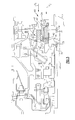
- FIG. 1 An example gas turbine engine 10 is schematically illustrated in Figure 1 . Although a high bypass engine is illustrated, it should be understood that the disclosure also relates to other types of gas turbine engines, such as turbo jets.
- the gas turbine engine 10 includes a compressor section 12, a combustor section 14 and a turbine section 16, which are arranged within a housing 24.
- high pressure stages of the compressor section 12 and the turbine section 16 are mounted on a first shaft 20, which is rotatable about an axis A.
- Low pressure stages of the compressor section 12 and turbine section 16 are mounted on a second shaft 22 which is coaxial with the first shaft 20 and rotatable about the axis A.
- the first shaft 20 rotationally drives a fan 18 that provides flow through a bypass flow path 19. It should be understood that the configuration illustrated in Figure 1 is exemplary only, and the disclosure may be used in other configurations.
- the first and second shafts 20, 22 are supported for rotation within the housing 24.
- one or more bearing compartments are provided within the housing 24 to isolate lubrication fluid from other areas of the engine 10.
- the housing 24 is typically constructed of multiple components to facilitate assembly.
- the housing 24 rotationally supports a shaft 26 for rotation with first and second bearings 28, 30.
- the first bearing 28, which is arranged at a front portion of the engine 10 in the example, is a ball bearing-type arrangement that permits very limited axial movement.
- the second bearing 30 is arranged rearward of the first bearing 28 and is disposed in a bearing compartment 32 that retains lubrication fluid within the compartment 32 to lubricate the second bearing 30.
- the second bearing 30 is a type which permits axial movement of the shaft 26 relative to the housing 24 due to thermal expansion and contraction that is typical during engine operation.
- first and second seal plates 34, 36 are mounted on the shaft 26 and provide rotating sealing surfaces.
- First and second seal assemblies 38, 40 are supported by the housing 24 and respectively provide a seal between the housing 24 and the first and second seal plates 34, 36.
- Example seal assemblies 40, 140, 240 are illustrated in Figures 3-5 . Too much closing force results in premature seal wear, while too little closing force results in inadequate sealing.
- the seal assemblies are configured to better accommodate axial displacement between the seal plate and the seal assemblies to maintain desired uniform closing forces throughout engine operation.
- An example seal assembly 40 is illustrated in Figure 3 , which is configured to provide a desired closing force.
- a seal 44 such as a carbon seal, is mounted to a carrier 42.
- the seal plate 36 is supported on the shaft 26.
- a guide assembly 46 is supported on a structure, such as the housing 24, which is a stationary or fixed structure.
- the guide assembly 46 includes multiple circumferentially arranged guide pins 48 supported by the housing 24.
- An intermediate carrier 56 is slideably supported by the guide pins 48 for axial movement in a first direction X1, which is parallel to the rotational axis A.
- the intermediate carrier 56 includes first and second flanges 55, 57.
- the first flange 55 includes an aperture 53 that slideably receives the guide pin 48.
- the guide pin 48 includes first and second spaced part ends 47, 49. The first end 47 is received by the housing 24.
- the second end 49 includes a retainer 50 that retains the intermediate carrier 56 on the guide pins 48 throughout operation.
- a first spring 52 is arranged between the first flange 55 and a fixed structure, such as the guide pin 48 (illustrated) or other fixed structure, such as a housing 24.
- the first spring 52 is a coil spring disposed about the guide pin 48.
- a second spring 54 is arranged between the carrier 42 and the intermediate carrier 56.
- the second spring 54 is an annular spring such as a bellows-type spring.
- the second spring 54 biases the carrier 42 and its mounted seal 44 in a second direction X2 that is parallel to the rotation axis A.
- the first and second springs, 52, 54 are in series with one another such that both springs operate to bias the seal 44 into engagement with the seal plate 36.
- the seal assembly 40 provides the desired closing force with the second spring 54 during initial engine operation. As axial gapping between the components changes during engine operation, the desired closing force applied by the second spring 54 may decrease. However, the first spring 52 supplements the closing force provided by the second spring 54 to maintain the desired closing force.
- the guide assembly 146 includes guide pins 148 having first and second opposing ends 147, 149.
- the first end 147 is mounted in the housing 124.
- the carrier 142 includes a flange 62 having an aperture 64 that slidably receives the guide pin 148.
- a stop 60 is provided on the guide pin 148.
- the first spring 152 is disposed on the guide pin 148 and is retained by a spring seat 58 that abuts the stop 60 to limit the travel of the first spring 152.
- the first spring 152 provides a closing force in a first direction X1.
- the second spring 54 is arranged between the housing 124 and the carrier 142, such that the first and second springs 152, 54 are arranged in parallel with one another.
- the carrier 142 supports the seal 44, which engages the second plate 36 mounted on the shaft 26.
- the second spring 54 provides a closing force in a second direction X2, which is the same direction as the first direction X1.
- the second spring 54 provides first and second conditions, respectively illustrated in Figures 4A and 4B .
- the first spring 152 just engages or is spaced from the carrier 142 such that little or no closing force from the first spring 152 is applied to the carrier 142.
- the second seal 54 provides the desired closing force.
- the flange 62 will move the spring seat 58 to the right, as illustrated in Figure 4B , at which time the first spring 152 will urge the seal 44 back toward the second seal plate 36.
- FIG. 5 Another seal assembly 240 is illustrated in Figure 5 .
- the first and second springs 252, 254 which are in series but oppose one another, have first and second directions X1, X2 that are opposite one another.
- the first spring 252 is arranged between the flange 262 and the retainer 50, which biases the carrier 242 away from the second seal plate 36.
- the second spring 54 which is arranged between the housing 224 and the carrier 242, urges the seal 44 into engagement with the second plate 36, which is mounted on the shaft 26.
- the first and second springs 252, 254 balance one another to maintain the desired closing force.
Abstract
Description
- This disclosure relates to mechanical face seals, and more particularly, to a mechanical face seal suitable for use with a gas turbine engine bearing compartment.
- The seal assembly includes a carrier mounted on a guide assembly having multiple circumferentially arranged guide pins. The carrier slides axially along the guide pins and supports a carbon seal that engages the rotating sealing surface. A spring element is arranged between the carrier and a fixed structure, such as a housing, to bias the seal into engagement with the rotating sealing surface.
- An axial face seal assembly includes first and second structures rotatable relative to one another about an axis. A carrier supports a seal that engages the second structure. The carrier is configured to move along the axis. First and second springs operatively are arranged between the first structure and the carrier. The first and second springs are configured to bias the carrier relative to the second structure respectively in first and second directions along the axis for providing a desired seal force on the second structure.
- A method of sealing a rotating structure includes biasing a seal toward a rotating sealing surface with a first spring to provide a desired axial seal force. The axial position of the seal relative to the rotating sealing surface is changed to an undesired axial closing force. The seal is biased with a second spring to achieve the desired axial closing force.
- The disclosure can be further understood by reference to the following detailed description when considered in connection with the accompanying drawings wherein:
-
Figure 1 is a schematic view of an example gas turbine engine. -
Figure 2 is a schematic view of a bearing compartment. -
Figure 3 is a schematic view of an example seal assembly. -
Figure 4A is a schematic view of another example seal assembly in a first condition. -
Figure 4B is a partial schematic view of a portion of the bearing assembly illustrated inFigure 4A in a second condition. -
Figure 5 is a schematic view of another example seal assembly. - Like reference numerals are used to illustrate like elements in the Figures.
- An example
gas turbine engine 10 is schematically illustrated inFigure 1 . Although a high bypass engine is illustrated, it should be understood that the disclosure also relates to other types of gas turbine engines, such as turbo jets. - The
gas turbine engine 10 includes acompressor section 12, acombustor section 14 and aturbine section 16, which are arranged within ahousing 24. In the example illustrated, high pressure stages of thecompressor section 12 and theturbine section 16 are mounted on afirst shaft 20, which is rotatable about an axis A. Low pressure stages of thecompressor section 12 andturbine section 16 are mounted on asecond shaft 22 which is coaxial with thefirst shaft 20 and rotatable about the axis A. In the example illustrated, thefirst shaft 20 rotationally drives afan 18 that provides flow through abypass flow path 19. It should be understood that the configuration illustrated inFigure 1 is exemplary only, and the disclosure may be used in other configurations. - The first and
second shafts housing 24. Typically, one or more bearing compartments are provided within thehousing 24 to isolate lubrication fluid from other areas of theengine 10. Thehousing 24 is typically constructed of multiple components to facilitate assembly. - Referring to the schematic in
Figure 2 , thehousing 24 rotationally supports ashaft 26 for rotation with first andsecond bearings 28, 30. The first bearing 28, which is arranged at a front portion of theengine 10 in the example, is a ball bearing-type arrangement that permits very limited axial movement. The second bearing 30 is arranged rearward of the first bearing 28 and is disposed in abearing compartment 32 that retains lubrication fluid within thecompartment 32 to lubricate the second bearing 30. The second bearing 30 is a type which permits axial movement of theshaft 26 relative to thehousing 24 due to thermal expansion and contraction that is typical during engine operation. - In the example, first and
second seal plates shaft 26 and provide rotating sealing surfaces. First andsecond seal assemblies housing 24 and respectively provide a seal between thehousing 24 and the first andsecond seal plates Example seal assemblies Figures 3-5 . Too much closing force results in premature seal wear, while too little closing force results in inadequate sealing. The seal assemblies are configured to better accommodate axial displacement between the seal plate and the seal assemblies to maintain desired uniform closing forces throughout engine operation. - An
example seal assembly 40 is illustrated inFigure 3 , which is configured to provide a desired closing force. Aseal 44, such as a carbon seal, is mounted to acarrier 42. Theseal plate 36 is supported on theshaft 26. Aguide assembly 46 is supported on a structure, such as thehousing 24, which is a stationary or fixed structure. Theguide assembly 46 includes multiple circumferentially arrangedguide pins 48 supported by thehousing 24. Anintermediate carrier 56 is slideably supported by theguide pins 48 for axial movement in a first direction X1, which is parallel to the rotational axis A. - The
intermediate carrier 56 includes first andsecond flanges first flange 55 includes anaperture 53 that slideably receives theguide pin 48. Theguide pin 48 includes first and second spaced part ends 47, 49. Thefirst end 47 is received by thehousing 24. Thesecond end 49 includes aretainer 50 that retains theintermediate carrier 56 on theguide pins 48 throughout operation. - A
first spring 52 is arranged between thefirst flange 55 and a fixed structure, such as the guide pin 48 (illustrated) or other fixed structure, such as ahousing 24. In the example, thefirst spring 52 is a coil spring disposed about theguide pin 48. - A
second spring 54 is arranged between thecarrier 42 and theintermediate carrier 56. In one example, thesecond spring 54 is an annular spring such as a bellows-type spring. Thesecond spring 54 biases thecarrier 42 and its mountedseal 44 in a second direction X2 that is parallel to the rotation axis A. In the example, the first and second springs, 52, 54 are in series with one another such that both springs operate to bias theseal 44 into engagement with theseal plate 36. - The
seal assembly 40 provides the desired closing force with thesecond spring 54 during initial engine operation. As axial gapping between the components changes during engine operation, the desired closing force applied by thesecond spring 54 may decrease. However, thefirst spring 52 supplements the closing force provided by thesecond spring 54 to maintain the desired closing force. - Referring to
Figures 4A and 4B , anotherseal assembly 140 is illustrated. Similar to the embodiment illustrated inFigure 3 , theguide assembly 146 includesguide pins 148 having first and secondopposing ends first end 147 is mounted in thehousing 124. Thecarrier 142 includes aflange 62 having anaperture 64 that slidably receives theguide pin 148. Astop 60 is provided on theguide pin 148. Thefirst spring 152 is disposed on theguide pin 148 and is retained by aspring seat 58 that abuts thestop 60 to limit the travel of thefirst spring 152. - The
first spring 152 provides a closing force in a first direction X1. Thesecond spring 54 is arranged between thehousing 124 and thecarrier 142, such that the first andsecond springs carrier 142 supports theseal 44, which engages thesecond plate 36 mounted on theshaft 26. Thesecond spring 54 provides a closing force in a second direction X2, which is the same direction as the first direction X1. - The
second spring 54 provides first and second conditions, respectively illustrated inFigures 4A and 4B . In the first condition, thefirst spring 152 just engages or is spaced from thecarrier 142 such that little or no closing force from thefirst spring 152 is applied to thecarrier 142. In this first condition, thesecond seal 54 provides the desired closing force. As thesecond seal plate 36 moves axially to the right, as illustrated inFigure 4A , theflange 62 will move thespring seat 58 to the right, as illustrated inFigure 4B , at which time thefirst spring 152 will urge theseal 44 back toward thesecond seal plate 36. - Another
seal assembly 240 is illustrated inFigure 5 . In this arrangement, the first andsecond springs 252, 254, which are in series but oppose one another, have first and second directions X1, X2 that are opposite one another. Thefirst spring 252 is arranged between theflange 262 and theretainer 50, which biases thecarrier 242 away from thesecond seal plate 36. Thesecond spring 54, which is arranged between thehousing 224 and thecarrier 242, urges theseal 44 into engagement with thesecond plate 36, which is mounted on theshaft 26. Thus, the first andsecond springs 252, 254 balance one another to maintain the desired closing force. - Although an example embodiment has been disclosed, a worker of ordinary skill in this art would recognize that certain modifications would come within the scope of the claims. For that reason, the following claims should be studied to determine their true scope and content.
Claims (15)
- An axial face seal assembly (40; 140;240) comprising:first and second structures (24,36) rotatable relative to one another about an axis (A);a carrier (42;142;242) supporting a seal (44) that engages the second structure (36), the carrier (42;142;242) configured to move along the axis (A); andfirst and second springs (52,54;152,54;252,54) operatively arranged between the first structure (24) and the carrier (42;142;242), the first and second springs (52,54;152,54;252,54) configured to bias the carrier (42;142;242) relative to the second structure (36) respectively in first and second directions (X1,X2) along the axis (A) for providing a desired closing force on the second structure (36).
- The axial face seal assembly according to claim 1, wherein the first structure is a static housing (24), and the second structure is a rotating seal plate (36).
- The axial face seal assembly according to claim 1 or 2, comprising a bearing compartment (32) housing a bearing (30), the second structure (36) disposed within the bearing compartment (32).
- The axial face seal assembly according to any preceding claim, comprising a guide assembly (46;146;246) mounted on the first structure (24), the guide assembly (46;146;246) supporting the first spring (52;152;252).
- The axial face seal assembly according to claim 4, wherein the guide assembly (46;146;246) includes a guide pin (48;148;248), and the first spring (52;152;252) is mounted coaxially with the guide pin (48;148;248).
- The axial face seal assembly according to claim 5, comprising an intermediate carrier (56) slidably supported by the guide pin (48), the second spring (54) arranged between the carrier (42) and the intermediate carrier (56), the first spring (52) biasing the intermediate carrier (56) toward the second structure (36).
- The axial face seal assembly according to claim 6, wherein the first spring (52) is arranged between the intermediate carrier (56) and the first structure (24).
- The axial face seal assembly according to claim 5, wherein the first spring (152) operatively disengages and engages from the carrier (142) respectively in first and second conditions.
- The axial face seal assembly according to claim 8, wherein the guide assembly (146) includes a stop (60), and the first spring (152) engages a spring seat (58) that engages the stop (60) in the second condition and disengages the stop (60) in the first condition.
- The axial face seal assembly according to claim 5, wherein the first spring (252) is arranged between a guide pin retainer (50) and the carrier (242) to bias the carrier (242) away from the second structure (36).
- The axial face seal assembly according to any preceding claim, wherein the second spring (54) is a bellows spring biasing the carrier (42;142;242) towards the second structure (36).
- The axial face seal assembly according to any preceding claim, wherein the first and second springs (52,54;252,54) are arranged in series with one another.
- The axial face seal assembly according to any of claims 1 to 11, wherein the first and second springs (152,252) are arranged in parallel relative to one another.
- The axial face seal assembly according to any preceding claim, wherein the first and second directions are opposite one another.
- A method of sealing a rotating structure comprising:biasing a seal (44) toward a rotating sealing surface (36) with a first spring (54) to provide a desired axial closing force;changing the axial position of the seal (44) relative to the rotating sealing surface (36) to an undesired axial closing force; andbiasing the seal (44) with a second spring (52;152;252) to achieve the desired axial closing force.
Applications Claiming Priority (1)
| Application Number | Priority Date | Filing Date | Title |
|---|---|---|---|
| US13/239,998 US20130075976A1 (en) | 2011-09-22 | 2011-09-22 | Compliant mounting of an axial face seal assembly |
Publications (2)
| Publication Number | Publication Date |
|---|---|
| EP2573330A2 true EP2573330A2 (en) | 2013-03-27 |
| EP2573330A3 EP2573330A3 (en) | 2016-11-02 |
Family
ID=47018799
Family Applications (1)
| Application Number | Title | Priority Date | Filing Date |
|---|---|---|---|
| EP12185182.8A Withdrawn EP2573330A3 (en) | 2011-09-22 | 2012-09-20 | Compliant mounting of an axial face seal assembly |
Country Status (2)
| Country | Link |
|---|---|
| US (1) | US20130075976A1 (en) |
| EP (1) | EP2573330A3 (en) |
Families Citing this family (4)
| Publication number | Priority date | Publication date | Assignee | Title |
|---|---|---|---|---|
| US10234036B2 (en) * | 2015-01-12 | 2019-03-19 | Rolls-Royce Corporation | Wide differential pressure range air riding carbon seal |
| US10260364B2 (en) | 2015-03-09 | 2019-04-16 | United Technologies Corporation | Sliding seal |
| US10202862B2 (en) * | 2015-04-08 | 2019-02-12 | United Technologies Corporation | Sliding seal |
| US11454324B2 (en) * | 2020-08-26 | 2022-09-27 | Raytheon Technologies Corporation | Face seal carrier arrester |
Family Cites Families (12)
| Publication number | Priority date | Publication date | Assignee | Title |
|---|---|---|---|---|
| US2420718A (en) * | 1944-09-01 | 1947-05-20 | Oscar G Odelius | Seal construction |
| US3443815A (en) * | 1966-07-14 | 1969-05-13 | Continental Illinois National | Pressure relieved labyrinth |
| US4687346A (en) * | 1986-09-02 | 1987-08-18 | United Technologies Corporation | Low profile bearing support structure |
| US5603510A (en) * | 1991-06-13 | 1997-02-18 | Sanders; William P. | Variable clearance seal assembly |
| US5174584A (en) * | 1991-07-15 | 1992-12-29 | General Electric Company | Fluid bearing face seal for gas turbine engines |
| US5749584A (en) * | 1992-11-19 | 1998-05-12 | General Electric Company | Combined brush seal and labyrinth seal segment for rotary machines |
| US6293555B1 (en) * | 2000-02-01 | 2001-09-25 | Josef Sedy | Secondary seal for non-contacting face seals |
| AU2002322389A1 (en) * | 2001-07-06 | 2003-01-21 | R And D Dynamics Corporation | Hydrodynamic foil face seal |
| US20030025275A1 (en) * | 2001-08-01 | 2003-02-06 | Miller Timothy F. | Mechanical face seal designs for small shafts |
| US6840519B2 (en) * | 2001-10-30 | 2005-01-11 | General Electric Company | Actuating mechanism for a turbine and method of retrofitting |
| US7938402B2 (en) * | 2004-05-28 | 2011-05-10 | Stein Seal Company | Air riding seal |
| US8714557B2 (en) * | 2005-10-28 | 2014-05-06 | United Technologies Corporation | Mechanical face seal housing with spring wall |
-
2011
- 2011-09-22 US US13/239,998 patent/US20130075976A1/en not_active Abandoned
-
2012
- 2012-09-20 EP EP12185182.8A patent/EP2573330A3/en not_active Withdrawn
Non-Patent Citations (1)
| Title |
|---|
| None |
Also Published As
| Publication number | Publication date |
|---|---|
| EP2573330A3 (en) | 2016-11-02 |
| US20130075976A1 (en) | 2013-03-28 |
Similar Documents
| Publication | Publication Date | Title |
|---|---|---|
| US7797941B2 (en) | Gas turbine engine systems involving hydrostatic face seals | |
| US10669882B2 (en) | Variable stator blade operating device | |
| US11028927B2 (en) | Wide differential pressure range air riding carbon seal | |
| EP2224103A2 (en) | Bearing damper with spring seal | |
| EP1852573A2 (en) | Sealing assembly for gas turbine engines | |
| EP3045783A1 (en) | Sliding seal | |
| EP2888451B1 (en) | Spring carrier and removable seal carrier | |
| EP3557088B1 (en) | Bearing centering spring and damper | |
| US20120211944A1 (en) | Self-adjusting seal for rotating turbomachinery | |
| EP2570612A1 (en) | Turbomachine secondary seal assembly | |
| EP3094826B1 (en) | Flanged spring guide for a face seal arrangement of a gas turbine engine | |
| EP2573330A2 (en) | Compliant mounting of an axial face seal assembly | |
| EP3012494B1 (en) | Sliding seal | |
| EP2060742A2 (en) | Dual Configuration seal assembly for a rotational assembly | |
| US20170268360A1 (en) | Magnetic seal system | |
| US20090033037A1 (en) | Seal assembly | |
| US20090051120A1 (en) | Gas Turbine Engine Systems Involving Hydrostatic Face Seals | |
| EP3159582A1 (en) | Shaft seal device and rotary machine | |
| GB2481839A (en) | Axially flexible bearing carrier for a pump | |
| EP2020542A1 (en) | Seal assembly | |
| US9829007B2 (en) | Turbine sealing system | |
| EP2233700B1 (en) | Self balancing face seals and gas turbine engine systems involving such seals | |
| EP3705759B1 (en) | Actively controlled contacting seal | |
| EP3557089B1 (en) | Bearing centering spring and damper | |
| CN117280144A (en) | Sealing device, rotary machine, and method for attaching sealing device |
Legal Events
| Date | Code | Title | Description |
|---|---|---|---|
| PUAI | Public reference made under article 153(3) epc to a published international application that has entered the european phase |
Free format text: ORIGINAL CODE: 0009012 |
|
| AK | Designated contracting states |
Kind code of ref document: A2 Designated state(s): AL AT BE BG CH CY CZ DE DK EE ES FI FR GB GR HR HU IE IS IT LI LT LU LV MC MK MT NL NO PL PT RO RS SE SI SK SM TR |
|
| AX | Request for extension of the european patent |
Extension state: BA ME |
|
| PUAL | Search report despatched |
Free format text: ORIGINAL CODE: 0009013 |
|
| RAP1 | Party data changed (applicant data changed or rights of an application transferred) |
Owner name: UNITED TECHNOLOGIES CORPORATION |
|
| AK | Designated contracting states |
Kind code of ref document: A3 Designated state(s): AL AT BE BG CH CY CZ DE DK EE ES FI FR GB GR HR HU IE IS IT LI LT LU LV MC MK MT NL NO PL PT RO RS SE SI SK SM TR |
|
| AX | Request for extension of the european patent |
Extension state: BA ME |
|
| RIC1 | Information provided on ipc code assigned before grant |
Ipc: F01D 25/18 20060101ALI20160923BHEP Ipc: F01D 11/00 20060101AFI20160923BHEP |
|
| STAA | Information on the status of an ep patent application or granted ep patent |
Free format text: STATUS: THE APPLICATION IS DEEMED TO BE WITHDRAWN |
|
| 18D | Application deemed to be withdrawn |
Effective date: 20170503 |