EP2573319A2 - Turbomachine conçue pour brûler un combustible contenant des cendres et procédé de combustion dudit combustible dans une turbomachine - Google Patents
Turbomachine conçue pour brûler un combustible contenant des cendres et procédé de combustion dudit combustible dans une turbomachine Download PDFInfo
- Publication number
- EP2573319A2 EP2573319A2 EP12184390A EP12184390A EP2573319A2 EP 2573319 A2 EP2573319 A2 EP 2573319A2 EP 12184390 A EP12184390 A EP 12184390A EP 12184390 A EP12184390 A EP 12184390A EP 2573319 A2 EP2573319 A2 EP 2573319A2
- Authority
- EP
- European Patent Office
- Prior art keywords
- ash
- airfoil members
- stage
- members
- airfoil
- Prior art date
- Legal status (The legal status is an assumption and is not a legal conclusion. Google has not performed a legal analysis and makes no representation as to the accuracy of the status listed.)
- Withdrawn
Links
Images

Classifications
-
- F—MECHANICAL ENGINEERING; LIGHTING; HEATING; WEAPONS; BLASTING
- F02—COMBUSTION ENGINES; HOT-GAS OR COMBUSTION-PRODUCT ENGINE PLANTS
- F02C—GAS-TURBINE PLANTS; AIR INTAKES FOR JET-PROPULSION PLANTS; CONTROLLING FUEL SUPPLY IN AIR-BREATHING JET-PROPULSION PLANTS
- F02C3/00—Gas-turbine plants characterised by the use of combustion products as the working fluid
- F02C3/20—Gas-turbine plants characterised by the use of combustion products as the working fluid using a special fuel, oxidant, or dilution fluid to generate the combustion products
-
- F—MECHANICAL ENGINEERING; LIGHTING; HEATING; WEAPONS; BLASTING
- F01—MACHINES OR ENGINES IN GENERAL; ENGINE PLANTS IN GENERAL; STEAM ENGINES
- F01D—NON-POSITIVE DISPLACEMENT MACHINES OR ENGINES, e.g. STEAM TURBINES
- F01D5/00—Blades; Blade-carrying members; Heating, heat-insulating, cooling or antivibration means on the blades or the members
- F01D5/12—Blades
- F01D5/14—Form or construction
- F01D5/141—Shape, i.e. outer, aerodynamic form
- F01D5/142—Shape, i.e. outer, aerodynamic form of the blades of successive rotor or stator blade-rows
-
- F—MECHANICAL ENGINEERING; LIGHTING; HEATING; WEAPONS; BLASTING
- F01—MACHINES OR ENGINES IN GENERAL; ENGINE PLANTS IN GENERAL; STEAM ENGINES
- F01D—NON-POSITIVE DISPLACEMENT MACHINES OR ENGINES, e.g. STEAM TURBINES
- F01D5/00—Blades; Blade-carrying members; Heating, heat-insulating, cooling or antivibration means on the blades or the members
- F01D5/12—Blades
- F01D5/14—Form or construction
- F01D5/148—Blades with variable camber, e.g. by ejection of fluid
-
- F—MECHANICAL ENGINEERING; LIGHTING; HEATING; WEAPONS; BLASTING
- F01—MACHINES OR ENGINES IN GENERAL; ENGINE PLANTS IN GENERAL; STEAM ENGINES
- F01D—NON-POSITIVE DISPLACEMENT MACHINES OR ENGINES, e.g. STEAM TURBINES
- F01D9/00—Stators
- F01D9/02—Nozzles; Nozzle boxes; Stator blades; Guide conduits, e.g. individual nozzles
-
- F—MECHANICAL ENGINEERING; LIGHTING; HEATING; WEAPONS; BLASTING
- F02—COMBUSTION ENGINES; HOT-GAS OR COMBUSTION-PRODUCT ENGINE PLANTS
- F02C—GAS-TURBINE PLANTS; AIR INTAKES FOR JET-PROPULSION PLANTS; CONTROLLING FUEL SUPPLY IN AIR-BREATHING JET-PROPULSION PLANTS
- F02C3/00—Gas-turbine plants characterised by the use of combustion products as the working fluid
- F02C3/20—Gas-turbine plants characterised by the use of combustion products as the working fluid using a special fuel, oxidant, or dilution fluid to generate the combustion products
- F02C3/26—Gas-turbine plants characterised by the use of combustion products as the working fluid using a special fuel, oxidant, or dilution fluid to generate the combustion products the fuel or oxidant being solid or pulverulent, e.g. in slurry or suspension
Definitions
- the subject matter disclosed herein relates to the art of turbomachines and, more particularly, to a turbomachine configured to burn ash-bearing fuel oils.
- turbomachines combust clean burning fuel oils to drive a turbine which powers, for example, generators, pumps and the like.
- Clean burning fuel oils such as natural gas, refined oil, syngas and the like are passed to a combustor and mixed with air and/or other diluents to form a combustible mixture.
- the mixture is combusted to form hot gases that are passed to a turbine portion.
- the hot gases are expanded through a series of stators and rotors.
- the rotors convert thermal energy from the hot gases to mechanical, rotational energy.
- the use of clean burning fuel oils results the formation of hot gases that are substantially ash free. Clean burning fuel oils also lead to lower overall emissions from the turbomachine.
- Heavier fuel oil or the fuel oil that remains after refining, is a lower cost alternative to current clean burning fuel oils. Heavier fuel oils create ash that is carried along with the hot gases through the turbine portion and deposited on internal components.
- a turbomachine includes a compressor portion, a combustor portion is fluidly connected to the compressor portion, and a turbine portion is fluidly connected to the combustor portion and mechanically coupled to the compressor portion.
- the combustor portion is configured and disposed to bum ash-bearing fuel oils.
- the turbine portion includes a first stage having a first plurality of airfoil members, and a second stage having a second plurality of airfoil members.
- the first plurality of airfoil members have a trailing edge discharge member fluidly connected to the compressor.
- the second plurality of airfoil members are clocked circumferentially relative to the first plurality of airfoil members.
- the first plurality of airfoil members are configured and disposed to direct an ash depleted flow upon corresponding adjacent ones of the second plurality of airfoil members.
- a method of burning ash-bearing fuel oils in a turbomachine includes combusting a heavy fuel to form an ash laden hot gas stream, guiding the ash laden hot gas stream toward a hot gas path of a turbine portion of the turbomachine, introducing a substantially ash free compressor air flow into the hot gas path, passing the substantially ash free compressor airflow and the ash laden hot gas stream across a plurality of first stage airfoil members, guiding the substantially ash free compressor airflow from each of the plurality of first stage airfoil members, forming an ash depleted air stream downstream of the trailing edge portion of each of the plurality of first stage nozzles, directing the ash depleted air stream toward an adjacent ones of a plurality of second stage airfoil members, and passing the ash depleted air stream across the corresponding adjacent ones of the plurality of second stage airfoil members.
- turbomachines are configured to bum clean, non-heavy, refined fuel oils.
- Refined, non-ash-bearing fuel oils burn clean and generally produce little or no ash when combusted in a turbomachine combustor.
- refined, non-ash-bearing fuel oils are rising in cost.
- the rise in fuel cost results in a significant increase in turbomachine operating costs.
- turbomachines are used by utility companies to generate power, as well as in a wide array of other industries, the rise in fuel costs will lead to increased consumer costs for anything from electric power, natural gas, as well as numerous other commodities.
- the term ash-bearing fuel oils should be understood to describe fuel oils that when burned produce ash.
- Ash-bearing fuel oils such as heavy fuel oil, heavy crude oil and light crude oil, or fuel left over after refining typically includes corrosive materials such as vanadium, nickel, iron, zinc, lead, calcium, magnesium and silicon, all of which lead to ash formation when combusted.
- corrosion inhibiters are also often times added to fuel to prevent corrosion that may result due to elements and products of combustion of Vanadium. The corrosion inhibiters also contribute to the ash content in the products of combustion entering turbomachine 2 following combustion. The ash is deposited on internal turbomachine parts such as nozzles and buckets.
- Turbomachine 2 includes a compressor portion 4 operatively connected to a turbine portion 6 through a combustor portion 10.
- Combustor portion 10 is configured to receive ash-bearing fuel oils that typically produce ash when combusted.
- Compressor portion 4 is also operatively connected with turbine portion 6 via a common compressor turbine shaft 12.
- turbine portion 6 includes a first stage 20 and a second stage 24. As shown, second stage 24 is positioned downstream from first stage 20. At this point it should be appreciated that the number of stages in turbine portion 6 can vary.
- First stage 20 includes a plurality of first stage stator airfoil members, one of which is indicated at 30, and a plurality of first stage rotor airfoil members, one of which is indicated at 32.
- First stage rotor airfoil members 32 are positioned down stream from first stage stator airfoil members 30.
- second stage 24 includes a plurality of first stage stator airfoil members, one of which is indicated at 40, and a plurality of second stage rotor airfoil members one of which is indicated at 42.
- Second stage rotor airfoil members 42 are positioned downstream from second stage stator airfoil members 40.
- hot, ash laden gases 50 pass from combustor portion 10 toward first stage 20.
- the hot, ash laden gases 50 flow over the plurality of first stage stator airfoil members 30 toward the plurality of first stage rotor airfoil members 32.
- the plurality of first stage stator airfoil members 30 conditions hot, ash laden gases 50 to flow along a desired flow path so as to impact the plurality of first stage rotor airfoil members 32.
- the plurality of first stage rotor airfoil members 32 begin to rotate.
- Hot, ash laden gases 50 then contoured to expand over subsequent stages to develop rotational energy that is output from turbine portion 6.
- first stage stator airfoil members 30, first stage rotor airfoil members 32, second stage stator airfoil members 40, and second stage rotor airfoil members 42 are configured and arranged to mitigate ash deposition on airfoils surfaces (not separately labeled).
- the exemplary embodiments provide a system for burning HFOs while avoiding maintenance issues, such as pitting, corrosion and the like associated with ash deposits.
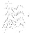
- each of the plurality of first stage stator airfoil members 30 includes a compressor air discharge member such as shown at 55 in FIG. 2 .
- Compressor air discharge member 55 is positioned at a trailing edge (not separately labeled) of each of the plurality of first stage stator airfoil members 30 and is fluidly connected with compressor portion 4.
- substantially ash free compressor air flow 57 is introduced into turbine portion 6.
- substantially ash free compressor air flow 57 forms an ash free layer about subsequent adjacent ones of the plurality of second stage stator airfoil members 40 to prevent or at least substantially reduce ash deposition onto airfoil surfaces.
- each of the plurality of first stage stator airfoil members 30 is formed having a chord length 58 that is longer than a chord length of a stator airfoil for a gas turbomachine the bums non-ash-bearing fuel oils.
- chord length 58 of each of the plurality of first stage stator airfoil members 30 is up to twice as long as the a chord length for stator airfoils in non-HFO burning gas turbomachines. The increase in chord length facilitates downstream substantially ash free compressor air flow.
- the plurality of second stage stator airfoil members 40 is clocked or circumferentially off-set from corresponding ones of each of the plurality of first stage stator airfoil members 30.
- clocking is achieved by rotationally positioning each of the plurality of second stage stator airfoil members 40 at an axial location that is between corresponding ones of each of the plurality of first stage stator airfoil members 30.
- clocking is achieved by reducing the number of the plurality of first stage stator airfoil members 30 and the plurality of second stage stator airfoil members 40 while also increasing an overall chord length of the airfoil members.
- stator airfoil members in each stage should be equal or an integer multiple thereof. Clocking the plurality of second stage stator airfoil members 40 relative to the plurality of first stage stator airfoil members 30 leads substantially ash free compressor air flow 57 to pass over subsequent adjacent airfoil surfaces to substantially reduce ash deposition.
- each of the plurality of first stage rotor airfoil members 32 includes a compressor air discharge member such as shown at 63.
- Compressor air discharge member 63 is positioned at a trailing edge (not separately labeled) of each of the plurality of first stage rotor airfoil members 32 and is fluidly connected with compressor portion 4.
- a second substantially ash free compressor air flow 67 is further introduced into turbine portion 6.
- second substantially ash free compressor air flow 67 forms an ash free layer about subsequent adjacent ones of the plurality of second stage rotor airfoil members 42 to prevent or at least substantially reduce ash deposition onto airfoil surfaces.
- the plurality of second stage rotor airfoil members 42 is clocked or circumferentially off-set from corresponding ones of each of the plurality of first stage rotor airfoil members 32.
- clocking is achieved by rotationally positioning each of the plurality of second stage rotor airfoil members 42 at an axial location that is between corresponding ones of each of the plurality of first stage rotor airfoil members 32.
- clocking is achieved by reducing the number of the plurality of second stage rotor airfoil members 42 relative to the number of the plurality of first stage rotor airfoil members 32.
- the number of the plurality of second stage rotor airfoil members 42 may be reduced to as much as half of the number of the plurality of first stage rotor airfoil members 32.
- clocking the plurality of second stage rotor airfoil members 42 relative to the plurality of first stage rotor airfoil members 32 leads second substantially ash free compressor air flow 67 to pass over subsequent adjacent airfoil surfaces to reduce ash deposition.
- turbomachine that is configured to bum ash-bearing fuel oils or fuel oils that that produce ash when combusted.
- the turbomachine is configured to direct a substantially ash free air flow over airfoil surface in the turbine portion to mitigate ash deposition and thus reduce the need for ash related maintenance.
- the introduction of the substantially ash free compressor air, along with the particular construction and orientation of the airfoil members creates a broad ash free cooling flow rate that passes over subsequent adjacent downstream airfoil surfaces to reduce ash deposition.
- stator airfoil members and rotor airfoil member are described as having an increased chord length and compressor discharge members, additional downstream stages may include airfoil members similarly constructed.
- ash deposition is still further reduced. That is the hot-ash laden flow will possess a lower kinetic energy that leads to lower impact velocities which, in turn, leads to a reduced ash deposition.
Landscapes
- Engineering & Computer Science (AREA)
- Mechanical Engineering (AREA)
- General Engineering & Computer Science (AREA)
- Chemical & Material Sciences (AREA)
- Combustion & Propulsion (AREA)
- Physics & Mathematics (AREA)
- Fluid Mechanics (AREA)
- Structures Of Non-Positive Displacement Pumps (AREA)
Applications Claiming Priority (1)
| Application Number | Priority Date | Filing Date | Title |
|---|---|---|---|
| US13/242,200 US20130074509A1 (en) | 2011-09-23 | 2011-09-23 | Turbomachine configured to burn ash-bearing fuel oils and method of burning ash-bearing fuel oils in a turbomachine |
Publications (1)
| Publication Number | Publication Date |
|---|---|
| EP2573319A2 true EP2573319A2 (fr) | 2013-03-27 |
Family
ID=46939587
Family Applications (1)
| Application Number | Title | Priority Date | Filing Date |
|---|---|---|---|
| EP12184390A Withdrawn EP2573319A2 (fr) | 2011-09-23 | 2012-09-14 | Turbomachine conçue pour brûler un combustible contenant des cendres et procédé de combustion dudit combustible dans une turbomachine |
Country Status (3)
| Country | Link |
|---|---|
| US (1) | US20130074509A1 (fr) |
| EP (1) | EP2573319A2 (fr) |
| CN (1) | CN103075256A (fr) |
Families Citing this family (1)
| Publication number | Priority date | Publication date | Assignee | Title |
|---|---|---|---|---|
| US20180149114A1 (en) * | 2016-11-30 | 2018-05-31 | Sikorsky Aircraft Corporation | Low infrared signature exhaust through active film cooling active mixing and acitve vane rotation |
Family Cites Families (8)
| Publication number | Priority date | Publication date | Assignee | Title |
|---|---|---|---|---|
| US5486091A (en) * | 1994-04-19 | 1996-01-23 | United Technologies Corporation | Gas turbine airfoil clocking |
| GB2293631B (en) * | 1994-09-30 | 1998-09-09 | Gen Electric | Composite fan blade trailing edge reinforcement |
| US6402458B1 (en) * | 2000-08-16 | 2002-06-11 | General Electric Company | Clock turbine airfoil cooling |
| US6554562B2 (en) * | 2001-06-15 | 2003-04-29 | Honeywell International, Inc. | Combustor hot streak alignment for gas turbine engine |
| US20100054922A1 (en) * | 2008-09-04 | 2010-03-04 | General Electric Company | Turbine airfoil clocking |
| US8297919B2 (en) * | 2008-10-31 | 2012-10-30 | General Electric Company | Turbine airfoil clocking |
| US8087253B2 (en) * | 2008-11-20 | 2012-01-03 | General Electric Company | Methods, apparatus and systems concerning the circumferential clocking of turbine airfoils in relation to combustor cans and the flow of cooling air through the turbine hot gas flowpath |
| US8720206B2 (en) * | 2009-05-14 | 2014-05-13 | General Electric Company | Methods and systems for inducing combustion dynamics |
-
2011
- 2011-09-23 US US13/242,200 patent/US20130074509A1/en not_active Abandoned
-
2012
- 2012-09-14 EP EP12184390A patent/EP2573319A2/fr not_active Withdrawn
- 2012-09-24 CN CN2012103567984A patent/CN103075256A/zh active Pending
Non-Patent Citations (1)
| Title |
|---|
| None |
Also Published As
| Publication number | Publication date |
|---|---|
| CN103075256A (zh) | 2013-05-01 |
| US20130074509A1 (en) | 2013-03-28 |
Similar Documents
| Publication | Publication Date | Title |
|---|---|---|
| US7559741B2 (en) | Turbomachine having an axially displaceable rotor | |
| US9476317B2 (en) | Forward step honeycomb seal for turbine shroud | |
| EP2204534B1 (fr) | Procédé de synchronisation des profiles d'aubes d'une turbine à gaz | |
| US10422233B2 (en) | Baffle insert for a gas turbine engine component and component with baffle insert | |
| US10280841B2 (en) | Baffle insert for a gas turbine engine component and method of cooling | |
| US9109455B2 (en) | Turbomachine blade tip shroud | |
| JP2011102582A (ja) | 翼形部熱シールド | |
| US10273976B2 (en) | Actively morphable vane | |
| US20130272888A1 (en) | Turbomachine blade tip shroud with parallel casing configuration | |
| US8657579B2 (en) | Blade for use with a rotary machine and method of assembling same rotary machine | |
| US20100054929A1 (en) | Turbine airfoil clocking | |
| US20150167979A1 (en) | First stage nozzle or transition nozzle configured to promote mixing of respective combustion streams downstream thereof before entry into a first stage bucket of a turbine | |
| US10337334B2 (en) | Gas turbine engine component with a baffle insert | |
| JP6557478B2 (ja) | タービンバケット及びタービンバケットの先端シュラウドをバランスさせるための方法 | |
| US10563543B2 (en) | Exhaust diffuser | |
| US8894376B2 (en) | Turbomachine blade with tip flare | |
| US8821125B2 (en) | Turbine blade having improved flutter capability and increased turbine stage output | |
| US10577947B2 (en) | Baffle insert for a gas turbine engine component | |
| US9045985B2 (en) | Stator vane bumper ring | |
| JP2014506972A5 (fr) | ||
| US20140130513A1 (en) | System and method for improving gas turbine performance at part-load operation | |
| US20160201571A1 (en) | Turbomachine having a gas flow aeromechanic system and method | |
| US8899909B2 (en) | Systems and methods for steam turbine wheel space cooling | |
| EP2573319A2 (fr) | Turbomachine conçue pour brûler un combustible contenant des cendres et procédé de combustion dudit combustible dans une turbomachine | |
| US20100054922A1 (en) | Turbine airfoil clocking |
Legal Events
| Date | Code | Title | Description |
|---|---|---|---|
| PUAI | Public reference made under article 153(3) epc to a published international application that has entered the european phase |
Free format text: ORIGINAL CODE: 0009012 |
|
| AK | Designated contracting states |
Kind code of ref document: A2 Designated state(s): AL AT BE BG CH CY CZ DE DK EE ES FI FR GB GR HR HU IE IS IT LI LT LU LV MC MK MT NL NO PL PT RO RS SE SI SK SM TR |
|
| AX | Request for extension of the european patent |
Extension state: BA ME |
|
| STAA | Information on the status of an ep patent application or granted ep patent |
Free format text: STATUS: THE APPLICATION IS DEEMED TO BE WITHDRAWN |
|
| 18D | Application deemed to be withdrawn |
Effective date: 20160401 |