EP2572973A1 - Front derailleur with frame support structure - Google Patents
Front derailleur with frame support structure Download PDFInfo
- Publication number
- EP2572973A1 EP2572973A1 EP12182140A EP12182140A EP2572973A1 EP 2572973 A1 EP2572973 A1 EP 2572973A1 EP 12182140 A EP12182140 A EP 12182140A EP 12182140 A EP12182140 A EP 12182140A EP 2572973 A1 EP2572973 A1 EP 2572973A1
- Authority
- EP
- European Patent Office
- Prior art keywords
- front derailleur
- bicycle
- bicycle front
- support
- support member
- Prior art date
- Legal status (The legal status is an assumption and is not a legal conclusion. Google has not performed a legal analysis and makes no representation as to the accuracy of the status listed.)
- Granted
Links
Images



Classifications
-
- B—PERFORMING OPERATIONS; TRANSPORTING
- B62—LAND VEHICLES FOR TRAVELLING OTHERWISE THAN ON RAILS
- B62M—RIDER PROPULSION OF WHEELED VEHICLES OR SLEDGES; POWERED PROPULSION OF SLEDGES OR SINGLE-TRACK CYCLES; TRANSMISSIONS SPECIALLY ADAPTED FOR SUCH VEHICLES
- B62M9/00—Transmissions characterised by use of an endless chain, belt, or the like
- B62M9/04—Transmissions characterised by use of an endless chain, belt, or the like of changeable ratio
- B62M9/06—Transmissions characterised by use of an endless chain, belt, or the like of changeable ratio using a single chain, belt, or the like
- B62M9/10—Transmissions characterised by use of an endless chain, belt, or the like of changeable ratio using a single chain, belt, or the like involving different-sized wheels, e.g. rear sprocket chain wheels selectively engaged by the chain, belt, or the like
- B62M9/12—Transmissions characterised by use of an endless chain, belt, or the like of changeable ratio using a single chain, belt, or the like involving different-sized wheels, e.g. rear sprocket chain wheels selectively engaged by the chain, belt, or the like the chain, belt, or the like being laterally shiftable, e.g. using a rear derailleur
- B62M9/131—Front derailleurs
- B62M9/135—Mounting the derailleur on the frame
Definitions
- a bicycle front derailleur is sometimes attached to the seat tube of a bicycle frame by a mounting fixture, which is fastened to the seat tube of the frame by welding, threaded fasteners or the like.
- This mounting fixture is sometimes called a direct-mounting seat or braze-on seat. Since such mounting fixtures are fastened to the seat tube beforehand, the chain guide of the derailleur cannot be disposed in a parallel position directly above the front sprocket in the case of systems in which a band is formed as an integral part of the front derailleur, unless the orientation is adjusted about an axis parallel to the seat tube following mounting.
- the present invention relates to a front derailleur which is fastened to a bicycle frame and which can be attached to a mounting fixture having a circular arcuate surface so that fine adjustments can be made by rotation about a first axis.
- a bicycle front derailleur that includes a chain guide configured to engage a bicycle chain and a mounting member operatively coupled to the chain guide.
- the mounting member includes a frame support structure that includes a contact member that is configured to contact the frame of the bicycle, and a support member mounted to the mounting member. The contact member is supported by the support member.
- the contact member is movably connected to the support member.
- the contact member includes a support plate and a resilient cover that covers the support plate and the resilient cover is movably connected to the support member.
- the resilient cover includes a recess for receiving the support member.
- the support member includes an end portion that has a semi-globular shape that is received in the recess of the resilient cover.
- the support member extends through an opening defined in the mounting member and the support member is movable with respect to the mounting member and within the opening.
- the contact member has an arcuate shape and when the derailleur is mounted on a seat tube of a bicycle, the contact member has a different diameter than the seat tube.
- FIG. 1 is a perspective view of a bicycle front derailleur with a frame support structure in accordance with a first preferred embodiment of the present invention
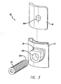
- FIG. 3 is an exploded view of the frame support structure of the bicycle front derailleur of FIG. 1 ;
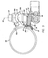
- FIG. 5 is a top plan view of the frame support structure and mounting member of the bicycle front derailleur of FIG. 1 with a portion cut away to show the support member;
- FIG. 6 is another top plan view of the frame support structure and mounting member of the bicycle front derailleur of FIG. 1 with a portion cut away to show the support member after adjustment.
- FIGS. 1-6 show a front derailleur 10 for a bicycle.
- the front derailleur 10 is mounted on the seat tube 100 of a bicycle.
- the front derailleur can be affixed to or mounted on other parts of a bicycle.
- the front derailleur 10 is a downswing-type derailleur.
- the front derailleur 10 preferably includes the main body or mounting member 40, a chain guide 41, an inner link 42 and an outer link 43.
- the mounting member 40 is mounted on the seat tube 100 and the chain guide 41 is configured to move between a retracted position and an extended position relative to the mounting member 40. It will be understood that in FIGS. 2-6 , the chain guide 41, inner and outer links 42 and 43 and associated components have been omitted for ease of viewing of the remaining components.
- the front derailleur 10 is mounted to the seat tube 100 using a mounting fixture 102 of the bicycle frame (not shown) to support the front derailleur 10 in a desired angular orientation.
- the mounting fixture 102 is fastened to the seat tube 100 by fastening means such as welding, fastener (bolt) or the like.
- the mounting fixture 102 has a bicycle frame fastening part 102a that can be fastened to the seat tube 100, a front derailleur mounting part 102b that is disposed on the bicycle frame fastening part 102a and that secures or fastens the front derailleur 10 in place.
- the front derailleur mounting part 102b secures the front derailleur 10 in position so that adjustment is possible about a first adjustment axis X1, which is generally parallel to the seat tube 100 and is disposed at a distance from the seat tube 100.
- the front derailleur mounting part 102b is formed by bending a long plate-form member in the vertical direction about the first adjustment axis X1 and includes circular arcuate surfaces 102c and 102d that are centered substantially on the first adjustment axis X1.
- a slot (not shown) which is used to fasten the front derailleur 10 so that adjustment is possible in the vertical direction is formed in the front derailleur mounting part 102b.
- the slot allows a first fastening bolt 33, which is used to fasten the front derailleur 10, to pass through from a first fastening direction that runs along a second mounting axis X2 orthogonal to the first adjustment axis X1.
- the width of the slot is a dimension that is considerably larger than the external diameter of the first fastening bolt 33, so that the first fastening bolt 33 can pass through at an inclination.
- the slot can be omitted and replaced by a circular opening, thus eliminating adjustment in the vertical direction.
- the bicycle frame fastening part 102a has a size that allows mounting on the outer circumferential surface equal to approximately a quarter circle of the seat tube 100.
- the circumference of the bicycle frame fastening part 102a is welded to the seat tube 100. In the case of such a construction, the position of the mounting fixture 102 cannot be later adjusted and the orientation of the front derailleur 10 is therefore adjusted by the front derailleur mounting part 102b.
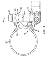
- the fixing part 45 of the mounting member 40 is formed in a generally semicircular arcuate shape as seen in a plan view (such as FIG. 4 ) so as to conform to the circular arcuate surface 102c of the front derailleur mounting part 102b.
- a screw hole (not shown) is formed in the fixing part of the mounting member 40 for threadedly receiving the first fastening bolt 33.
- the chain guide 41 guides the chain (not shown) to either of the at least two front chain rings (not shown) by moving corresponding shift positions that include a low shift position disposed over the small diameter or inside chain ring, and a top shift position disposed over the large diameter or outside chain ring.
- the chain guide 41 is connected to the outer ends of the inner link 42 and the outer link 43 so as to move between the retracted position and the extended position relative to the mounting member 40.
- the inner link 42 and the outer link 43 are pivotally coupled at their inner ends to the mounting member 40 and pivotally coupled at their outer ends to the chain guide 41.
- the inner link 42 and the outer link 43 are arranged so as to be generally parallel to each other.
- the inner and outer links 42 and 43 form a four bar linkage assembly with the mounting member 40 and the chain guide 41 in order to move the chain guide 41 between the retracted position and the extended position.
- the chain guide 41 has an outer plate 41 a and an inner plate 41b that define a chain receiving slot therebetween.
- the outer plate 41 a is disposed on the outside (the side distant from the seat tube 100), and the inner plate 41b is disposed on the inside.
- the inner link 42 is disposed beneath the mounting member 40 in a state in which the mounting member 40 is mounted on the seat tube 100, and both ends of this link are connected to the mounting member 40 and chain guide 41 in a manner that allows the link to pivot freely.
- One end of the inner link 42 is connected to the mounting member 40 so that the inner link 42 can swing freely.
- the chain guide 41 is connected to the other end of the inner link 42 so that the chain guide can swing freely.
- the outer link 43 is a link which is disposed generally parallel to the inner link 42 and in which both ends of the link are connected to the mounting member 40 and the chain guide 41 in positions that are more distant from the mounting member 40 than the inner link 42 is, so that outer link 43 can pivot freely.
- a cable anchoring arm 44 is provided on the outer link 43.
- a cable anchoring part 44a for bolting down the inner cable of the gear shift cable (not shown) is disposed on the extended distal end of the cable anchoring arm 44.
- a screw hole (not shown) that is used for fastening by the first fastening bolt 33 in the direction of the axis X2 orthogonal to the first adjustment axis X1 is formed in the mounting member 40, and a screw hole 40d is formed along a third displacement axis X3 that is orthogonal to the first adjustment axis X1, but not orthogonal to the second mounting axis X2.
- a support member 23, that is preferably threaded with a recessed hexagonal socket is mounted in the screw hole 40d so that the support member 23 is free to advance and retract.
- a hexagonal recessed socket that can be turned by an Allen key is formed in the base end of the support member 23, and the distal end portion 23a has a semi-spherical or globular shape.
- a contact member 25 mounted on the distal end 23a of the support member 23 is a contact member 25 that contacts the outer circumferential surface of the seat tube 100, as shown in FIGS. 4-6 .
- the contact member 25 comprises a resilient support plate cover 27 that houses a support plate 28 and that includes a receiver member 29 that has a recess 29a defined therein for receiving the distal end 23a of the support member 23.
- the contact member 25 can comprise a single resilient member.
- the support plate 28 can be omitted.
- the support plate cover 27 and support plate 28 have an arcuate shape.
- opening 29a extends through the back surface of the support plate cover and support plate 28 includes an indentation 28a in the back surface thereof, which receives and seats the distal end 23a of the support member 23.
- the distal end portion 23a is movably supported within opening 29a and that distal end portion 23a and opening 29a (together with indentation 28) form a "ball joint" arrangement.
- the resilient support plate cover 28 is made of a resilient material, such as a resin or the like, and the support plate 28 is made of a metal.
- this is not a limitation on the present invention.
- the arcuate shape of the contact member 25 and the components thereof has a different diameter than that of the seat tube 100, it is preferred that the contact member and the seat tube can have a similar diameter so that the entire front surface of the contact member is flush against the seat tube.
- the first fastening bolt 33 is positioned in a lightly tightened state, so that the vertical position can be adjusted and adjustment about the first adjustment axis X1 is possible.
- the vertical position is then adjusted so that the gap between the addendum circle of the large-diameter sprocket and the lower edge part of the outer plate is approximately 1 to 3 mm, and the orientation about the first adjustment axis X1 is adjusted so that the outer plate is disposed in a position directly above the smaller-diameter sprocket and parallel to the smaller-diameter sprocket.
- the first fastening bolt 33 is tightened.
- FIG. 5 also shows an access opening 46 so that a tool/wrench can be passed through the axis opening 46 to access the support member 23.
Landscapes
- Engineering & Computer Science (AREA)
- Chemical & Material Sciences (AREA)
- Combustion & Propulsion (AREA)
- Transportation (AREA)
- Mechanical Engineering (AREA)
- Clamps And Clips (AREA)
- Motorcycle And Bicycle Frame (AREA)
- Devices For Conveying Motion By Means Of Endless Flexible Members (AREA)
Description
- The present invention relates to a front derailleur for a bicycle that includes a frame support structure.
- A bicycle front derailleur is sometimes attached to the seat tube of a bicycle frame by a mounting fixture, which is fastened to the seat tube of the frame by welding, threaded fasteners or the like. This mounting fixture is sometimes called a direct-mounting seat or braze-on seat. Since such mounting fixtures are fastened to the seat tube beforehand, the chain guide of the derailleur cannot be disposed in a parallel position directly above the front sprocket in the case of systems in which a band is formed as an integral part of the front derailleur, unless the orientation is adjusted about an axis parallel to the seat tube following mounting.
-
US 2007/0117666A1 , which is incorporated by reference in its entirety herein, teaches a bicycle front derailleur which is capable of adjustment. However, a need exists for an improved front derailleur with adjustment capabilities. The present invention relates to a front derailleur which is fastened to a bicycle frame and which can be attached to a mounting fixture having a circular arcuate surface so that fine adjustments can be made by rotation about a first axis. - In accordance with a first aspect of the present invention there is provided a bicycle front derailleur that includes a chain guide configured to engage a bicycle chain and a mounting member operatively coupled to the chain guide. The mounting member includes a frame support structure that includes a contact member that is configured to contact the frame of the bicycle, and a support member mounted to the mounting member. The contact member is supported by the support member.
- In a preferred embodiment, the contact member is movably connected to the support member. In a preferred embodiment, the contact member includes a support plate and a resilient cover that covers the support plate and the resilient cover is movably connected to the support member. The resilient cover includes a recess for receiving the support member. In a preferred embodiment, the support member includes an end portion that has a semi-globular shape that is received in the recess of the resilient cover. In a preferred embodiment, the support member extends through an opening defined in the mounting member and the support member is movable with respect to the mounting member and within the opening. In a preferred embodiment, the contact member has an arcuate shape and when the derailleur is mounted on a seat tube of a bicycle, the contact member has a different diameter than the seat tube.
- The invention, together with additional features and advantages thereof, may be best understood by reference to the following description.
-
FIG. 1 is a perspective view of a bicycle front derailleur with a frame support structure in accordance with a first preferred embodiment of the present invention; -
FIG. 2 is an exploded view of the mounting member and frame support structure of the bicycle front derailleur ofFIG. 1 ; -
FIG. 3 is an exploded view of the frame support structure of the bicycle front derailleur ofFIG. 1 ; -
FIG. 4 is a top plan view of the frame support structure and mounting member of the bicycle front derailleur ofFIG. 1 ; -
FIG. 5 is a top plan view of the frame support structure and mounting member of the bicycle front derailleur ofFIG. 1 with a portion cut away to show the support member; and -
FIG. 6 is another top plan view of the frame support structure and mounting member of the bicycle front derailleur ofFIG. 1 with a portion cut away to show the support member after adjustment. - The following description and drawings are illustrative and are not to be construed as limiting. Numerous specific details are described to provide a thorough understanding of the disclosure. However, in certain instances, well-known or conventional details are not described in order to avoid obscuring the description. References to one or an embodiment in the present disclosure can be, but not necessarily are references to the same embodiment; and, such references mean at least one of the embodiments.
- Reference in this specification to "one embodiment" or "an embodiment" means that a particular feature, structure, or characteristic described in connection with the embodiment is included in at least one embodiment of the-disclosure. The appearances of the phrase "in one embodiment" in various places in the specification are not necessarily all referring to the same embodiment, nor are separate or alternative embodiments mutually exclusive of other embodiments. Moreover, various features are described which may be exhibited by some embodiments and not by others. Similarly, various requirements are described which may be requirements for some embodiments but not other embodiments.
- It will be appreciated that terms such as "front," "back," "top," "bottom," "side," "short," "long," "up," "down," and "below" used herein are merely for ease of description and refer to the orientation of the components as shown in the figures. It should be understood that any orientation of the components described herein is within the scope of the present invention.
- Referring now to the drawings, which are for purposes of illustrating the present invention and not for purposes of limiting the same,
FIGS. 1-6 show afront derailleur 10 for a bicycle. In a preferred embodiment, as shown inFIGS. 4-6 , thefront derailleur 10 is mounted on theseat tube 100 of a bicycle. However, this is not a limitation on the present invention, and the front derailleur can be affixed to or mounted on other parts of a bicycle. - As shown in
FIG. 1 thefront derailleur 10 is a downswing-type derailleur. Thefront derailleur 10 preferably includes the main body or mountingmember 40, a chain guide 41, aninner link 42 and anouter link 43. Themounting member 40 is mounted on theseat tube 100 and the chain guide 41 is configured to move between a retracted position and an extended position relative to themounting member 40. It will be understood that inFIGS. 2-6 , the chain guide 41, inner andouter links - As shown in
FIG. 4 thefront derailleur 10 is mounted to theseat tube 100 using amounting fixture 102 of the bicycle frame (not shown) to support thefront derailleur 10 in a desired angular orientation. Themounting fixture 102 is fastened to theseat tube 100 by fastening means such as welding, fastener (bolt) or the like. Themounting fixture 102 has a bicycle frame fasteningpart 102a that can be fastened to theseat tube 100, a frontderailleur mounting part 102b that is disposed on the bicycle frame fasteningpart 102a and that secures or fastens thefront derailleur 10 in place. - The front
derailleur mounting part 102b secures thefront derailleur 10 in position so that adjustment is possible about a first adjustment axis X1, which is generally parallel to theseat tube 100 and is disposed at a distance from theseat tube 100. The frontderailleur mounting part 102b is formed by bending a long plate-form member in the vertical direction about the first adjustment axis X1 and includes circulararcuate surfaces front derailleur 10 so that adjustment is possible in the vertical direction is formed in the frontderailleur mounting part 102b. The slot allows afirst fastening bolt 33, which is used to fasten thefront derailleur 10, to pass through from a first fastening direction that runs along a second mounting axis X2 orthogonal to the first adjustment axis X1. The width of the slot is a dimension that is considerably larger than the external diameter of thefirst fastening bolt 33, so that thefirst fastening bolt 33 can pass through at an inclination. In another embodiment, the slot can be omitted and replaced by a circular opening, thus eliminating adjustment in the vertical direction. - The bicycle frame fastening
part 102a has a size that allows mounting on the outer circumferential surface equal to approximately a quarter circle of theseat tube 100. The circumference of the bicycle frame fasteningpart 102a is welded to theseat tube 100. In the case of such a construction, the position of themounting fixture 102 cannot be later adjusted and the orientation of thefront derailleur 10 is therefore adjusted by the frontderailleur mounting part 102b. - The
mounting member 40 of thefront derailleur 10 is secured to themounting fixture 102, while the chain guide 41 is free to move in the gear shift direction toward or away from themounting member 40 via the inner andouter links mounting member 40 and the chain guide 41. - The
fixing part 45 of themounting member 40 is formed in a generally semicircular arcuate shape as seen in a plan view (such asFIG. 4 ) so as to conform to the circulararcuate surface 102c of the frontderailleur mounting part 102b. A screw hole (not shown) is formed in the fixing part of themounting member 40 for threadedly receiving thefirst fastening bolt 33. - The chain guide 41 guides the chain (not shown) to either of the at least two front chain rings (not shown) by moving corresponding shift positions that include a low shift position disposed over the small diameter or inside chain ring, and a top shift position disposed over the large diameter or outside chain ring. The chain guide 41 is connected to the outer ends of the
inner link 42 and theouter link 43 so as to move between the retracted position and the extended position relative to themounting member 40. Theinner link 42 and theouter link 43 are pivotally coupled at their inner ends to themounting member 40 and pivotally coupled at their outer ends to the chain guide 41. Theinner link 42 and theouter link 43 are arranged so as to be generally parallel to each other. Thus, the inner andouter links mounting member 40 and the chain guide 41 in order to move the chain guide 41 between the retracted position and the extended position. In the present embodiment, the chain guide 41 has an outer plate 41 a and aninner plate 41b that define a chain receiving slot therebetween. The outer plate 41 a is disposed on the outside (the side distant from the seat tube 100), and theinner plate 41b is disposed on the inside. - As shown in
FIG. 1 , theinner link 42 is disposed beneath the mountingmember 40 in a state in which the mountingmember 40 is mounted on theseat tube 100, and both ends of this link are connected to the mountingmember 40 and chain guide 41 in a manner that allows the link to pivot freely. One end of theinner link 42 is connected to the mountingmember 40 so that theinner link 42 can swing freely. The chain guide 41 is connected to the other end of theinner link 42 so that the chain guide can swing freely. - The
outer link 43 is a link which is disposed generally parallel to theinner link 42 and in which both ends of the link are connected to the mountingmember 40 and the chain guide 41 in positions that are more distant from the mountingmember 40 than theinner link 42 is, so thatouter link 43 can pivot freely. Acable anchoring arm 44 is provided on theouter link 43. A cable anchoring part 44a for bolting down the inner cable of the gear shift cable (not shown) is disposed on the extended distal end of thecable anchoring arm 44. - As shown in
FIGS. 5-6 , a screw hole (not shown) that is used for fastening by thefirst fastening bolt 33 in the direction of the axis X2 orthogonal to the first adjustment axis X1 is formed in the mountingmember 40, and ascrew hole 40d is formed along a third displacement axis X3 that is orthogonal to the first adjustment axis X1, but not orthogonal to the second mounting axis X2. Asupport member 23, that is preferably threaded with a recessed hexagonal socket is mounted in thescrew hole 40d so that thesupport member 23 is free to advance and retract. A hexagonal recessed socket that can be turned by an Allen key is formed in the base end of thesupport member 23, and thedistal end portion 23a has a semi-spherical or globular shape. Mounted on thedistal end 23a of thesupport member 23 is acontact member 25 that contacts the outer circumferential surface of theseat tube 100, as shown inFIGS. 4-6 . - As shown in
FIGS. 2-3 , in a preferred embodiment, thecontact member 25 comprises a resilientsupport plate cover 27 that houses asupport plate 28 and that includes areceiver member 29 that has arecess 29a defined therein for receiving thedistal end 23a of thesupport member 23. In another embodiment, thecontact member 25 can comprise a single resilient member. In other words, thesupport plate 28 can be omitted. Preferably, thesupport plate cover 27 andsupport plate 28 have an arcuate shape. As shown inFIGS. 5 and6 , in a preferred embodiment,opening 29a extends through the back surface of the support plate cover andsupport plate 28 includes anindentation 28a in the back surface thereof, which receives and seats thedistal end 23a of thesupport member 23. It will be understood that, in this embodiment, thedistal end portion 23a is movably supported withinopening 29a and thatdistal end portion 23a andopening 29a (together with indentation 28) form a "ball joint" arrangement. In a preferred embodiment, the resilientsupport plate cover 28 is made of a resilient material, such as a resin or the like, and thesupport plate 28 is made of a metal. However, this is not a limitation on the present invention. As shown inFIGS. 4-6 , although the arcuate shape of thecontact member 25 and the components thereof (thesupport plate cover 27 and support plate 28) has a different diameter than that of theseat tube 100, it is preferred that the contact member and the seat tube can have a similar diameter so that the entire front surface of the contact member is flush against the seat tube. - An example of how the
front derailleur 10 of the present invention can be adjusted will now be described. Initially, thefirst fastening bolt 33 is positioned in a lightly tightened state, so that the vertical position can be adjusted and adjustment about the first adjustment axis X1 is possible. The vertical position is then adjusted so that the gap between the addendum circle of the large-diameter sprocket and the lower edge part of the outer plate is approximately 1 to 3 mm, and the orientation about the first adjustment axis X1 is adjusted so that the outer plate is disposed in a position directly above the smaller-diameter sprocket and parallel to the smaller-diameter sprocket. When the adjustments are completed, thefirst fastening bolt 33 is tightened. In cases where thecontact member 25 does not contact theseat tube 100, a wrench is placed in the recessed hexagonal socket in thesupport member 23 via an opening in theouter link 43 and thesupport member 23 andcontact member 25 are advanced until the contact member 25 (the resilient cover 27) comes into contact with theseat tube 100. It will be appreciated by those skilled in the art that the chain guide 41 is more stably supported by thecontact member 25 when the chain guide 41 is in the extended position compared to a derailleur without the contact member 15. - As is shown in
FIG. 5 , the support member 23 (and the third axis X3) are arranged such that they form an angle with the second axis X2 between about 78° to about 86°.FIG. 5 also shows an access opening 46 so that a tool/wrench can be passed through theaxis opening 46 to access thesupport member 23. - While certain aspects of the disclosure are presented below in certain claim forms, the inventors contemplate the various aspects of the disclosure in any number of claim forms. For example, while only one aspect of the disclosure is recited as a means-plus-function claim, other aspects may likewise be embodied as a means-plus-function claim, or in other forms, such as being embodied in a computer-readable medium. Accordingly, the applicant reserves the right to add additional claims after filing the application to pursue such additional claim forms for other aspects of the disclosure.
- Accordingly, although exemplary embodiments of the invention have been shown and described, it is to be understood that all the terms used herein are descriptive rather than limiting, and that many changes, modifications, and substitutions may be made by one having ordinary skill in the art without departing from the spirit and scope of the invention.
Claims (12)
- A bicycle front derailleur comprising:a chain guide configured to engage a bicycle chain, anda mounting member operatively coupled to the chain guide, wherein the mounting member includes a frame support structure that includes a contact member that is configured to contact the frame of the bicycle and a support member mounted to the mounting member, wherein the contact member is supported by the support member.
- The bicycle front derailleur of claim 1 wherein the contact member is movably connected to the support member.
- The bicycle front derailleur of claim 1 wherein the contact member comprises a support plate and a resilient cover that covers the support plate.
- The bicycle front derailleur of claim 3 wherein the resilient cover is movably connected to the support member.
- The bicycle front derailleur of claim 4 wherein the resilient cover includes a recess for receiving the support member.
- The bicycle front derailleur of claim 5 wherein the support member includes an end portion that is received in the recess of the resilient cover, and wherein the end portion has a semi-globular shape.
- The bicycle front derailleur of claim 1 wherein the support member extends through an opening defined in the mounting member, and wherein the support member is movable with respect to the mounting member and within the opening.
- The bicycle front derailleur of claim 4, wherein the resilient cover is made of a resin and the support plate is made of a metal.
- The bicycle front derailleur of claim 6 wherein the support plate has an indentation defined in a back surface thereof, and wherein the end portion of the support member is seated in the indentation.
- The bicycle front derailleur of claim 1 wherein the contact member has an arcuate shape.
- The bicycle front derailleur of claim 10 wherein when the derailleur is mounted on a seat tube of a bicycle, the contact member has a different diameter than the seat tube.
- The bicycle front derailleur of claim 3 wherein the resilient cover and the support plate have an arcuate shape.
Applications Claiming Priority (2)
| Application Number | Priority Date | Filing Date | Title |
|---|---|---|---|
| US13/238,345 US8678963B2 (en) | 2011-09-21 | 2011-09-21 | Bicycle front derailleur |
| US13/250,827 US8808123B2 (en) | 2011-09-30 | 2011-09-30 | Front derailleur with frame support structure |
Publications (2)
| Publication Number | Publication Date |
|---|---|
| EP2572973A1 true EP2572973A1 (en) | 2013-03-27 |
| EP2572973B1 EP2572973B1 (en) | 2015-04-22 |
Family
ID=46727139
Family Applications (1)
| Application Number | Title | Priority Date | Filing Date |
|---|---|---|---|
| EP20120182140 Active EP2572973B1 (en) | 2011-09-21 | 2012-08-29 | Front derailleur with frame support structure |
Country Status (3)
| Country | Link |
|---|---|
| EP (1) | EP2572973B1 (en) |
| CN (1) | CN103010395B (en) |
| TW (1) | TWI526365B (en) |
Cited By (4)
| Publication number | Priority date | Publication date | Assignee | Title |
|---|---|---|---|---|
| CN104773256A (en) * | 2014-01-14 | 2015-07-15 | 株式会社岛野 | Front derailleur |
| CN107215427A (en) * | 2016-03-22 | 2017-09-29 | 株式会社岛野 | Bicycle Front Derailleur with Mounting Bracket |
| EP3354554A1 (en) * | 2017-01-26 | 2018-08-01 | J.D Components Co., Ltd. | Fastening device for bicycle front derailleur and bicycle front derailleur and bicycle using the fastening device |
| EP3441294A1 (en) * | 2017-08-07 | 2019-02-13 | Campagnolo S.r.l. | Bicycle component comprising a removable clamping device for fixing to a tubular element of the bicycle |
Families Citing this family (5)
| Publication number | Priority date | Publication date | Assignee | Title |
|---|---|---|---|---|
| US9434448B2 (en) * | 2014-10-31 | 2016-09-06 | Shimano Inc. | Bicycle derailleur |
| CN107042867B (en) * | 2016-02-05 | 2020-10-09 | 禧玛诺(新)私人有限公司 | Bicycle front derailleur |
| US10407128B2 (en) * | 2016-09-30 | 2019-09-10 | Shimano Inc. | Bicycle derailleur |
| US10131404B2 (en) * | 2017-02-09 | 2018-11-20 | Shimano Inc. | Bicycle front derailleur |
| TWI752306B (en) * | 2019-03-20 | 2022-01-11 | 彥豪金屬工業股份有限公司 | Bicycle derailleur |
Citations (4)
| Publication number | Priority date | Publication date | Assignee | Title |
|---|---|---|---|---|
| US4199997A (en) * | 1977-02-21 | 1980-04-29 | Shimano Industrial Company Limited | Front derailleur |
| US20040185975A1 (en) * | 2003-03-20 | 2004-09-23 | Po-Cheng Chen | Chain-poking device for derailleurs |
| EP1787902A2 (en) * | 2005-11-21 | 2007-05-23 | Shimano Inc. | Front derailleur with mounting fixture |
| EP2520480A1 (en) * | 2011-05-02 | 2012-11-07 | Campagnolo S.r.l. | Bicycle front derailleur body and device for adjustable rest fo such derailleur body on a tube of a bicycle frame |
Family Cites Families (1)
| Publication number | Priority date | Publication date | Assignee | Title |
|---|---|---|---|---|
| US7677998B2 (en) * | 2006-01-31 | 2010-03-16 | Shimano Inc. | Bicycle front derailleur |
-
2012
- 2012-03-02 TW TW101106901A patent/TWI526365B/en active
- 2012-08-29 EP EP20120182140 patent/EP2572973B1/en active Active
- 2012-09-21 CN CN201210356924.6A patent/CN103010395B/en active Active
Patent Citations (5)
| Publication number | Priority date | Publication date | Assignee | Title |
|---|---|---|---|---|
| US4199997A (en) * | 1977-02-21 | 1980-04-29 | Shimano Industrial Company Limited | Front derailleur |
| US20040185975A1 (en) * | 2003-03-20 | 2004-09-23 | Po-Cheng Chen | Chain-poking device for derailleurs |
| EP1787902A2 (en) * | 2005-11-21 | 2007-05-23 | Shimano Inc. | Front derailleur with mounting fixture |
| US20070117666A1 (en) | 2005-11-21 | 2007-05-24 | Shimano Inc. | Front derailleur with mounting fixture |
| EP2520480A1 (en) * | 2011-05-02 | 2012-11-07 | Campagnolo S.r.l. | Bicycle front derailleur body and device for adjustable rest fo such derailleur body on a tube of a bicycle frame |
Cited By (5)
| Publication number | Priority date | Publication date | Assignee | Title |
|---|---|---|---|---|
| CN104773256A (en) * | 2014-01-14 | 2015-07-15 | 株式会社岛野 | Front derailleur |
| CN107215427A (en) * | 2016-03-22 | 2017-09-29 | 株式会社岛野 | Bicycle Front Derailleur with Mounting Bracket |
| CN107215427B (en) * | 2016-03-22 | 2020-02-14 | 株式会社岛野 | Bicycle front derailleur with mounting bracket |
| EP3354554A1 (en) * | 2017-01-26 | 2018-08-01 | J.D Components Co., Ltd. | Fastening device for bicycle front derailleur and bicycle front derailleur and bicycle using the fastening device |
| EP3441294A1 (en) * | 2017-08-07 | 2019-02-13 | Campagnolo S.r.l. | Bicycle component comprising a removable clamping device for fixing to a tubular element of the bicycle |
Also Published As
| Publication number | Publication date |
|---|---|
| EP2572973B1 (en) | 2015-04-22 |
| TW201313553A (en) | 2013-04-01 |
| CN103010395A (en) | 2013-04-03 |
| CN103010395B (en) | 2015-09-02 |
| TWI526365B (en) | 2016-03-21 |
Similar Documents
| Publication | Publication Date | Title |
|---|---|---|
| EP2572973B1 (en) | Front derailleur with frame support structure | |
| US8808123B2 (en) | Front derailleur with frame support structure | |
| US10099739B2 (en) | Bicycle guard and drive unit equipped with bicycle guard | |
| CN107042867B (en) | Bicycle front derailleur | |
| US10793222B1 (en) | Bicycle derailleur having upper and lower alignment assemblies | |
| US8961342B2 (en) | Chain guide assembly with movable member | |
| TWI743374B (en) | Bicycle rear derailleur | |
| US9776685B2 (en) | Front derailleur | |
| US8864611B2 (en) | Front derailleur | |
| JP5077963B2 (en) | Fixture | |
| US9061730B2 (en) | Front derailleur with contact member | |
| US10065705B2 (en) | Bicycle derailleur | |
| EP1787902A2 (en) | Front derailleur with mounting fixture | |
| US20140263507A1 (en) | Angle-adjustable water bottle cage | |
| US20110317444A1 (en) | Vehicle headlight structure | |
| TW201706176A (en) | Bicycle operating device | |
| TW202423783A (en) | Bicycle operating devices | |
| CA2984870C (en) | Remote control lever assembly | |
| TWM551999U (en) | Bicycle front derailleur | |
| JP6579988B2 (en) | Rod holder | |
| TW201817642A (en) | Bicycle component operating device | |
| CN107842833A (en) | Lamp mounting bracket | |
| US20170092243A1 (en) | Musical Instrument Carrier | |
| US8403282B2 (en) | Clamp device | |
| JP2008302738A (en) | Outer mirror device for vehicle |
Legal Events
| Date | Code | Title | Description |
|---|---|---|---|
| PUAI | Public reference made under article 153(3) epc to a published international application that has entered the european phase |
Free format text: ORIGINAL CODE: 0009012 |
|
| AK | Designated contracting states |
Kind code of ref document: A1 Designated state(s): AL AT BE BG CH CY CZ DE DK EE ES FI FR GB GR HR HU IE IS IT LI LT LU LV MC MK MT NL NO PL PT RO RS SE SI SK SM TR |
|
| AX | Request for extension of the european patent |
Extension state: BA ME |
|
| 17P | Request for examination filed |
Effective date: 20130927 |
|
| RBV | Designated contracting states (corrected) |
Designated state(s): AL AT BE BG CH CY CZ DE DK EE ES FI FR GB GR HR HU IE IS IT LI LT LU LV MC MK MT NL NO PL PT RO RS SE SI SK SM TR |
|
| 17Q | First examination report despatched |
Effective date: 20140203 |
|
| GRAP | Despatch of communication of intention to grant a patent |
Free format text: ORIGINAL CODE: EPIDOSNIGR1 |
|
| INTG | Intention to grant announced |
Effective date: 20141210 |
|
| GRAS | Grant fee paid |
Free format text: ORIGINAL CODE: EPIDOSNIGR3 |
|
| GRAA | (expected) grant |
Free format text: ORIGINAL CODE: 0009210 |
|
| AK | Designated contracting states |
Kind code of ref document: B1 Designated state(s): AL AT BE BG CH CY CZ DE DK EE ES FI FR GB GR HR HU IE IS IT LI LT LU LV MC MK MT NL NO PL PT RO RS SE SI SK SM TR |
|
| REG | Reference to a national code |
Ref country code: GB Ref legal event code: FG4D |
|
| REG | Reference to a national code |
Ref country code: CH Ref legal event code: EP |
|
| REG | Reference to a national code |
Ref country code: AT Ref legal event code: REF Ref document number: 723045 Country of ref document: AT Kind code of ref document: T Effective date: 20150515 |
|
| REG | Reference to a national code |
Ref country code: IE Ref legal event code: FG4D |
|
| REG | Reference to a national code |
Ref country code: DE Ref legal event code: R096 Ref document number: 602012006822 Country of ref document: DE Effective date: 20150603 |
|
| REG | Reference to a national code |
Ref country code: NL Ref legal event code: VDEP Effective date: 20150422 |
|
| REG | Reference to a national code |
Ref country code: AT Ref legal event code: MK05 Ref document number: 723045 Country of ref document: AT Kind code of ref document: T Effective date: 20150422 |
|
| REG | Reference to a national code |
Ref country code: LT Ref legal event code: MG4D |
|
| PG25 | Lapsed in a contracting state [announced via postgrant information from national office to epo] |
Ref country code: NL Free format text: LAPSE BECAUSE OF FAILURE TO SUBMIT A TRANSLATION OF THE DESCRIPTION OR TO PAY THE FEE WITHIN THE PRESCRIBED TIME-LIMIT Effective date: 20150422 |
|
| PG25 | Lapsed in a contracting state [announced via postgrant information from national office to epo] |
Ref country code: PT Free format text: LAPSE BECAUSE OF FAILURE TO SUBMIT A TRANSLATION OF THE DESCRIPTION OR TO PAY THE FEE WITHIN THE PRESCRIBED TIME-LIMIT Effective date: 20150824 Ref country code: NO Free format text: LAPSE BECAUSE OF FAILURE TO SUBMIT A TRANSLATION OF THE DESCRIPTION OR TO PAY THE FEE WITHIN THE PRESCRIBED TIME-LIMIT Effective date: 20150722 Ref country code: FI Free format text: LAPSE BECAUSE OF FAILURE TO SUBMIT A TRANSLATION OF THE DESCRIPTION OR TO PAY THE FEE WITHIN THE PRESCRIBED TIME-LIMIT Effective date: 20150422 Ref country code: LT Free format text: LAPSE BECAUSE OF FAILURE TO SUBMIT A TRANSLATION OF THE DESCRIPTION OR TO PAY THE FEE WITHIN THE PRESCRIBED TIME-LIMIT Effective date: 20150422 Ref country code: ES Free format text: LAPSE BECAUSE OF FAILURE TO SUBMIT A TRANSLATION OF THE DESCRIPTION OR TO PAY THE FEE WITHIN THE PRESCRIBED TIME-LIMIT Effective date: 20150422 Ref country code: HR Free format text: LAPSE BECAUSE OF FAILURE TO SUBMIT A TRANSLATION OF THE DESCRIPTION OR TO PAY THE FEE WITHIN THE PRESCRIBED TIME-LIMIT Effective date: 20150422 |
|
| PG25 | Lapsed in a contracting state [announced via postgrant information from national office to epo] |
Ref country code: LV Free format text: LAPSE BECAUSE OF FAILURE TO SUBMIT A TRANSLATION OF THE DESCRIPTION OR TO PAY THE FEE WITHIN THE PRESCRIBED TIME-LIMIT Effective date: 20150422 Ref country code: RS Free format text: LAPSE BECAUSE OF FAILURE TO SUBMIT A TRANSLATION OF THE DESCRIPTION OR TO PAY THE FEE WITHIN THE PRESCRIBED TIME-LIMIT Effective date: 20150422 Ref country code: IS Free format text: LAPSE BECAUSE OF FAILURE TO SUBMIT A TRANSLATION OF THE DESCRIPTION OR TO PAY THE FEE WITHIN THE PRESCRIBED TIME-LIMIT Effective date: 20150822 Ref country code: GR Free format text: LAPSE BECAUSE OF FAILURE TO SUBMIT A TRANSLATION OF THE DESCRIPTION OR TO PAY THE FEE WITHIN THE PRESCRIBED TIME-LIMIT Effective date: 20150723 Ref country code: AT Free format text: LAPSE BECAUSE OF FAILURE TO SUBMIT A TRANSLATION OF THE DESCRIPTION OR TO PAY THE FEE WITHIN THE PRESCRIBED TIME-LIMIT Effective date: 20150422 |
|
| REG | Reference to a national code |
Ref country code: DE Ref legal event code: R097 Ref document number: 602012006822 Country of ref document: DE |
|
| PG25 | Lapsed in a contracting state [announced via postgrant information from national office to epo] |
Ref country code: DK Free format text: LAPSE BECAUSE OF FAILURE TO SUBMIT A TRANSLATION OF THE DESCRIPTION OR TO PAY THE FEE WITHIN THE PRESCRIBED TIME-LIMIT Effective date: 20150422 Ref country code: EE Free format text: LAPSE BECAUSE OF FAILURE TO SUBMIT A TRANSLATION OF THE DESCRIPTION OR TO PAY THE FEE WITHIN THE PRESCRIBED TIME-LIMIT Effective date: 20150422 |
|
| PLBE | No opposition filed within time limit |
Free format text: ORIGINAL CODE: 0009261 |
|
| STAA | Information on the status of an ep patent application or granted ep patent |
Free format text: STATUS: NO OPPOSITION FILED WITHIN TIME LIMIT |
|
| PG25 | Lapsed in a contracting state [announced via postgrant information from national office to epo] |
Ref country code: CZ Free format text: LAPSE BECAUSE OF FAILURE TO SUBMIT A TRANSLATION OF THE DESCRIPTION OR TO PAY THE FEE WITHIN THE PRESCRIBED TIME-LIMIT Effective date: 20150422 Ref country code: SK Free format text: LAPSE BECAUSE OF FAILURE TO SUBMIT A TRANSLATION OF THE DESCRIPTION OR TO PAY THE FEE WITHIN THE PRESCRIBED TIME-LIMIT Effective date: 20150422 Ref country code: RO Free format text: LAPSE BECAUSE OF NON-PAYMENT OF DUE FEES Effective date: 20150422 Ref country code: PL Free format text: LAPSE BECAUSE OF FAILURE TO SUBMIT A TRANSLATION OF THE DESCRIPTION OR TO PAY THE FEE WITHIN THE PRESCRIBED TIME-LIMIT Effective date: 20150422 |
|
| 26N | No opposition filed |
Effective date: 20160125 |
|
| PG25 | Lapsed in a contracting state [announced via postgrant information from national office to epo] |
Ref country code: MC Free format text: LAPSE BECAUSE OF FAILURE TO SUBMIT A TRANSLATION OF THE DESCRIPTION OR TO PAY THE FEE WITHIN THE PRESCRIBED TIME-LIMIT Effective date: 20150422 Ref country code: LU Free format text: LAPSE BECAUSE OF FAILURE TO SUBMIT A TRANSLATION OF THE DESCRIPTION OR TO PAY THE FEE WITHIN THE PRESCRIBED TIME-LIMIT Effective date: 20150829 |
|
| REG | Reference to a national code |
Ref country code: CH Ref legal event code: PL |
|
| PG25 | Lapsed in a contracting state [announced via postgrant information from national office to epo] |
Ref country code: CH Free format text: LAPSE BECAUSE OF NON-PAYMENT OF DUE FEES Effective date: 20150831 Ref country code: LI Free format text: LAPSE BECAUSE OF NON-PAYMENT OF DUE FEES Effective date: 20150831 |
|
| PG25 | Lapsed in a contracting state [announced via postgrant information from national office to epo] |
Ref country code: SI Free format text: LAPSE BECAUSE OF FAILURE TO SUBMIT A TRANSLATION OF THE DESCRIPTION OR TO PAY THE FEE WITHIN THE PRESCRIBED TIME-LIMIT Effective date: 20150422 |
|
| REG | Reference to a national code |
Ref country code: IE Ref legal event code: MM4A |
|
| REG | Reference to a national code |
Ref country code: FR Ref legal event code: ST Effective date: 20160429 |
|
| PG25 | Lapsed in a contracting state [announced via postgrant information from national office to epo] |
Ref country code: IE Free format text: LAPSE BECAUSE OF NON-PAYMENT OF DUE FEES Effective date: 20150829 |
|
| PG25 | Lapsed in a contracting state [announced via postgrant information from national office to epo] |
Ref country code: FR Free format text: LAPSE BECAUSE OF NON-PAYMENT OF DUE FEES Effective date: 20150831 Ref country code: BE Free format text: LAPSE BECAUSE OF FAILURE TO SUBMIT A TRANSLATION OF THE DESCRIPTION OR TO PAY THE FEE WITHIN THE PRESCRIBED TIME-LIMIT Effective date: 20150422 |
|
| PG25 | Lapsed in a contracting state [announced via postgrant information from national office to epo] |
Ref country code: MT Free format text: LAPSE BECAUSE OF FAILURE TO SUBMIT A TRANSLATION OF THE DESCRIPTION OR TO PAY THE FEE WITHIN THE PRESCRIBED TIME-LIMIT Effective date: 20150422 |
|
| GBPC | Gb: european patent ceased through non-payment of renewal fee |
Effective date: 20160829 |
|
| PG25 | Lapsed in a contracting state [announced via postgrant information from national office to epo] |
Ref country code: BG Free format text: LAPSE BECAUSE OF FAILURE TO SUBMIT A TRANSLATION OF THE DESCRIPTION OR TO PAY THE FEE WITHIN THE PRESCRIBED TIME-LIMIT Effective date: 20150422 Ref country code: HU Free format text: LAPSE BECAUSE OF FAILURE TO SUBMIT A TRANSLATION OF THE DESCRIPTION OR TO PAY THE FEE WITHIN THE PRESCRIBED TIME-LIMIT; INVALID AB INITIO Effective date: 20120829 Ref country code: SM Free format text: LAPSE BECAUSE OF FAILURE TO SUBMIT A TRANSLATION OF THE DESCRIPTION OR TO PAY THE FEE WITHIN THE PRESCRIBED TIME-LIMIT Effective date: 20150422 |
|
| PG25 | Lapsed in a contracting state [announced via postgrant information from national office to epo] |
Ref country code: SE Free format text: LAPSE BECAUSE OF FAILURE TO SUBMIT A TRANSLATION OF THE DESCRIPTION OR TO PAY THE FEE WITHIN THE PRESCRIBED TIME-LIMIT Effective date: 20150422 Ref country code: CY Free format text: LAPSE BECAUSE OF FAILURE TO SUBMIT A TRANSLATION OF THE DESCRIPTION OR TO PAY THE FEE WITHIN THE PRESCRIBED TIME-LIMIT Effective date: 20150422 |
|
| PG25 | Lapsed in a contracting state [announced via postgrant information from national office to epo] |
Ref country code: GB Free format text: LAPSE BECAUSE OF NON-PAYMENT OF DUE FEES Effective date: 20160829 |
|
| PG25 | Lapsed in a contracting state [announced via postgrant information from national office to epo] |
Ref country code: TR Free format text: LAPSE BECAUSE OF FAILURE TO SUBMIT A TRANSLATION OF THE DESCRIPTION OR TO PAY THE FEE WITHIN THE PRESCRIBED TIME-LIMIT Effective date: 20150422 |
|
| PGFP | Annual fee paid to national office [announced via postgrant information from national office to epo] |
Ref country code: IT Payment date: 20170824 Year of fee payment: 6 |
|
| PG25 | Lapsed in a contracting state [announced via postgrant information from national office to epo] |
Ref country code: MK Free format text: LAPSE BECAUSE OF FAILURE TO SUBMIT A TRANSLATION OF THE DESCRIPTION OR TO PAY THE FEE WITHIN THE PRESCRIBED TIME-LIMIT Effective date: 20150422 |
|
| PG25 | Lapsed in a contracting state [announced via postgrant information from national office to epo] |
Ref country code: AL Free format text: LAPSE BECAUSE OF FAILURE TO SUBMIT A TRANSLATION OF THE DESCRIPTION OR TO PAY THE FEE WITHIN THE PRESCRIBED TIME-LIMIT Effective date: 20150422 |
|
| PG25 | Lapsed in a contracting state [announced via postgrant information from national office to epo] |
Ref country code: IT Free format text: LAPSE BECAUSE OF NON-PAYMENT OF DUE FEES Effective date: 20180829 |
|
| P01 | Opt-out of the competence of the unified patent court (upc) registered |
Effective date: 20230428 |
|
| PGFP | Annual fee paid to national office [announced via postgrant information from national office to epo] |
Ref country code: DE Payment date: 20250702 Year of fee payment: 14 |