EP2572946A1 - Verriegelungsschutz für eine elektrische Lenkverriegelung - Google Patents
Verriegelungsschutz für eine elektrische Lenkverriegelung Download PDFInfo
- Publication number
- EP2572946A1 EP2572946A1 EP12006624A EP12006624A EP2572946A1 EP 2572946 A1 EP2572946 A1 EP 2572946A1 EP 12006624 A EP12006624 A EP 12006624A EP 12006624 A EP12006624 A EP 12006624A EP 2572946 A1 EP2572946 A1 EP 2572946A1
- Authority
- EP
- European Patent Office
- Prior art keywords
- locking
- drive wheel
- protection according
- blocking surface
- blocking
- Prior art date
- Legal status (The legal status is an assumption and is not a legal conclusion. Google has not performed a legal analysis and makes no representation as to the accuracy of the status listed.)
- Granted
Links
- 230000000903 blocking effect Effects 0.000 claims description 34
- 238000004519 manufacturing process Methods 0.000 description 6
- 229910000831 Steel Inorganic materials 0.000 description 3
- 239000000463 material Substances 0.000 description 3
- 239000010959 steel Substances 0.000 description 3
- 229920002430 Fibre-reinforced plastic Polymers 0.000 description 2
- XAGFODPZIPBFFR-UHFFFAOYSA-N aluminium Chemical compound [Al] XAGFODPZIPBFFR-UHFFFAOYSA-N 0.000 description 2
- 229910052782 aluminium Inorganic materials 0.000 description 2
- 239000011151 fibre-reinforced plastic Substances 0.000 description 2
- 238000000034 method Methods 0.000 description 2
- 238000011161 development Methods 0.000 description 1
- 230000018109 developmental process Effects 0.000 description 1
- 230000000694 effects Effects 0.000 description 1
- 238000001746 injection moulding Methods 0.000 description 1
- 238000009434 installation Methods 0.000 description 1
- 238000003754 machining Methods 0.000 description 1
- 230000007257 malfunction Effects 0.000 description 1
- 238000005457 optimization Methods 0.000 description 1
- 239000004033 plastic Substances 0.000 description 1
- 229920003023 plastic Polymers 0.000 description 1
- 230000002265 prevention Effects 0.000 description 1
- 230000001012 protector Effects 0.000 description 1
- 238000005245 sintering Methods 0.000 description 1
Images


Classifications
-
- B—PERFORMING OPERATIONS; TRANSPORTING
- B60—VEHICLES IN GENERAL
- B60R—VEHICLES, VEHICLE FITTINGS, OR VEHICLE PARTS, NOT OTHERWISE PROVIDED FOR
- B60R16/00—Electric or fluid circuits specially adapted for vehicles and not otherwise provided for; Arrangement of elements of electric or fluid circuits specially adapted for vehicles and not otherwise provided for
-
- B—PERFORMING OPERATIONS; TRANSPORTING
- B60—VEHICLES IN GENERAL
- B60R—VEHICLES, VEHICLE FITTINGS, OR VEHICLE PARTS, NOT OTHERWISE PROVIDED FOR
- B60R25/00—Fittings or systems for preventing or indicating unauthorised use or theft of vehicles
- B60R25/01—Fittings or systems for preventing or indicating unauthorised use or theft of vehicles operating on vehicle systems or fittings, e.g. on doors, seats or windscreens
- B60R25/02—Fittings or systems for preventing or indicating unauthorised use or theft of vehicles operating on vehicle systems or fittings, e.g. on doors, seats or windscreens operating on the steering mechanism
- B60R25/021—Fittings or systems for preventing or indicating unauthorised use or theft of vehicles operating on vehicle systems or fittings, e.g. on doors, seats or windscreens operating on the steering mechanism restraining movement of the steering column or steering wheel hub, e.g. restraining means controlled by ignition switch
- B60R25/0215—Fittings or systems for preventing or indicating unauthorised use or theft of vehicles operating on vehicle systems or fittings, e.g. on doors, seats or windscreens operating on the steering mechanism restraining movement of the steering column or steering wheel hub, e.g. restraining means controlled by ignition switch using electric means, e.g. electric motors or solenoids
- B60R25/02153—Fittings or systems for preventing or indicating unauthorised use or theft of vehicles operating on vehicle systems or fittings, e.g. on doors, seats or windscreens operating on the steering mechanism restraining movement of the steering column or steering wheel hub, e.g. restraining means controlled by ignition switch using electric means, e.g. electric motors or solenoids comprising a locking member radially and linearly moved towards the steering column
Definitions
- the invention relates to a locking protection for an electric steering lock for a vehicle with an electrically driven drive wheel and a locking pin.
- the locking pin is secured by a locking surface of the drive wheel in an unlocked state of the steering lock.
- the invention is therefore based on the object to provide a locking protection for an electric steering lock for a vehicle, which avoids the disadvantages of the prior art, which is inexpensive to manufacture, has a compact design, cost, fast and reliable error prevention mount and can be used for a wide variety of vehicle types due to a different kinematics.
- the locking element arranged on the drive wheel is designed as a blocking surface.
- the locking element arranged on the locking element is advantageously designed as a securing groove.
- the blocking surface is advantageously formed rigidly and / or in one piece with the drive wheel.
- the drive wheel can be made for example of plastic or any other material.
- the blocking surface of the locking protection extends over an arc angle of 30 ° to 90 °, preferably 60 °. This can provide a high level of operational reliability over a wide range.
- the locking pin of the locking protector advantageously has a freewheeling groove which traverses the blocking surface between a blocking position for blocking a steering spindle and a release position for releasing the steering spindle. Due to the thus achieved minimum distance between the drive wheel and the locking pin a very compact design can be achieved become.
- the locking bolt can be made either as a sintered component or as a steel component, which is subsequently machined by means of machining or electroerosion processes.
- the locking pin can be made for example as a rotary part or sintered component.
- the freewheeling groove advantageously has a greater extent than the securing groove. This safe locking unlocking and locking the steering spindle is provided with a compact design.
- the height of the securing groove essentially corresponds to the wall thickness of the blocking surface, which in particular still has an oversize and thus allows clearance.
- the extent of the blocking surface in the release position is aligned substantially perpendicular to the translational movement direction of the locking pin.
- the blocking surface is advantageously substantially axially protruding from the drive wheel as a ring segment-shaped portion. Again, this allows a compact design and a simple production.
- the blocking surface advantageously protrudes substantially radially from the drive wheel as a fan-shaped section. Again, this allows due to the small distance between the locking pin and the drive wheel a compact design and ease of manufacture, with even more installation options are made possible due to this second embodiment of the electric steering locks.
- FIGS. 1 and 2 schematically show a first embodiment of a locking protection for an electric steering lock 1 for a vehicle with an electrically driven drive wheel 2 and a locking pin.
- the rotation axis R of the drive wheel 2 is oriented perpendicular to an extension direction of the lock pin 3.
- a lifting movement H of the locking pin 3 is thus perpendicular to the axis of rotation R of the drive wheel 2.
- a first portion of the drive wheel 2 is a substantially axially extending locking surface 2c, as a ring segment-shaped projecting portion formed.
- This blocking surface 2c is preferably integrally formed on the drive wheel 2 in this embodiment and extends over an arc angle of 60 °.
- the wall thickness in this case essentially corresponds to an interference counterpart to be secured.
- a cam 2a for driving a control pin 4 is integrally formed on an outer surface of the drive wheel 2.
- the control pin 4 is non-positively connected to the locking pin 3 and transmits the lifting movement of the cam 2a to the locking pin 3.
- a toothing 2b is formed radially.
- This toothing 2 b is also formed integrally with the drive wheel 2.
- Adjacent to the central portion 2 pulse generators are arranged in an upper portion of the drive wheel and designed to detect the rotation angle or the current position of the drive wheel 2 and thus also the current position of the lift curve. As a result, a statement about the locking or unlocking state can be clearly made.
- the locking pin 3 is guided in a locking pin bearing, not shown here, substantially free of play and translationally along its vertical axis.
- the locking pin 3 is substantially an elongated, rectangular cross-section with corresponding longitudinal and transverse axis.
- the faces are essentially curved slightly outward, ie convex.
- the two side surfaces are flat.
- a freewheel groove 3a is formed in an upper portion, on one of the curved surfaces.
- the length or height of the freewheel groove 3a corresponds to the stroke of the cam 2a of the drive wheel 2 and allows a translational movement of the locking pin 3, when the locking surface 2c of the drive wheel 2 is pivoted in the direction of the locking pin 3 during a locking or unlocking and the Freewheel groove 3a passes through.
- the locking pin 3 has a securing groove 3b.
- the locking pin 3 In an unlocked position of the steering lock 3 is the locking pin 3 via the locking groove 3b in engagement with the locking surface 2c of the drive wheel 2. Due to the rotational movement of the drive wheel 2, the locking protection 2c is brought by pivoting the locking surface 2c in engagement with the securing groove 3b.
- the length or height of the securing groove 3b corresponds to the wall thickness of the securing surface 2c plus a game.
- a substantially wedge or runner-shaped portion At a lower portion of the locking pin 3 there is a substantially wedge or runner-shaped portion. This section is for locking in engagement with a steering column. This wedge-shaped portion is aligned to a (not shown) steering column axis in order to effect an optimal locking engagement in a mounted on the steering column Nutenkranz.
- a sintered steel such as D32.
- control pin 4 In the assembled state, the control pin 4 is in engagement with the drive wheel 2 through the cam 2a.
- the control pin 4 is frictionally connected to the locking pin 3 in a central portion and converts the Rotary movement of the drive wheel 2 by means of the cam 2a and the control pin in a translational movement of the locking pin 3 to.
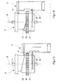
- the locking pin 3 ' is aligned in the longitudinal axis direction parallel to a rotation axis R' of a drive wheel 2 '.
- the lifting movement of the locking pin 3 'thus also takes place parallel to the axis of rotation R'.
- This blocking surface 2c 'in this embodiment is preferably formed integrally on the drive wheel 2' and extends over an arc segment of 60 ° in the radial direction.
- the wall thickness in this case essentially corresponds to an interference counterpart to be secured.
- a toothing 2b' is formed radially. As a result, a toothed engagement with a helical gear is possible.
- This toothing 2b ' is also formed integrally with the drive wheel 2'.
- the diameter of the toothing 2b ' is less than the diameter of the blocking surface 2c', so that the blocking surface 2c 'is radially projecting relative to the toothing 2b' is executed.
- This lift curve 2a ' in turn extends to the outer surface of the drive wheel 2' and is thus integrally formed. Furthermore, in this upper section, pulse generators are arranged and designed to detect the angle of rotation or the current position of the drive wheel 2 'and thus also the current position of the lift curve 2a'. As a result, a statement about the locking or unlocking status can be clearly made.
- the locking pin 3 ' in the upper portion of two non-illustrated non-uniform grooves on two opposite, planar side surfaces. On one of the two curved to the drive wheel 2 'facing surfaces a groove connecting the two grooves is still formed. These three grooves allow a fail-safe assembly of an actuator 4 ', since all three grooves differ. About this actuator 4 ', the locking pin 3' by the lifting cam 2a 'of the drive wheel 2' translationally moved. Due to the rotational movement of the drive wheel 2 ', the locking guard 2c' is also brought into engagement with the securing groove 3b 'by swiveling in the blocking surface 2c'.
- a locking pin 3, 3 ' is formed as a rotating part of C45.
- a locking pin 3 for a locking pin 3, 3 'both other geometric shapes such as, cubes, cylinders, etc., as well as other materials such as aluminum, fiber reinforced plastics, etc., conceivable. Also, an integral design of a control pin or actuator 4, 4 'with the locking pin 3; 3 'is conceivable.
- a drive wheel 2, 2 'made of a fiber-reinforced plastic by injection molding but other materials such as aluminum, steel grades, C45, etc., are conceivable.
Landscapes
- Engineering & Computer Science (AREA)
- Mechanical Engineering (AREA)
- Lock And Its Accessories (AREA)
Abstract
Description
- Die Erfindung betrifft einen Verriegelungsschutz für eine elektrische Lenkverriegelung für ein Fahrzeug mit einem elektrisch angetriebenen Antriebsrad und einem Sperrbolzen. Dabei wird der Sperrbolzen durch eine Sperrfläche des Antriebsrads in einem unverriegelten Zustand der Lenkverriegelung gesichert.
- Aus dem bekannten Stand der Technik sind eine Vielzahl von Lenkverriegelungen bekannt, die jedoch in der Regel keinen Verriegelungsschutz zur Vermeidung einer unfreiwilligen Sperrung einer Lenkspindel, z.B. während der Fahrt, aufweisen.
- Der Erfindung liegt daher die Aufgabe zugrunde, einen Verriegelungsschutz für eine elektrische Lenkverriegelung für ein Fahrzeug zur Verfügung zu stellen, welche die Nachteile des Standes der Technik vermeidet, die kostengünstig zu fertigen ist, eine kompakte Bauform aufweist, kostengünstig, schnell und bei sicherer Fehlervermeidung zu montieren und für unterschiedlichste Fahrzeugtypen aufgrund einer unterschiedlichen Kinematik verwendbar ist.
- Diese Aufgabe wird durch einen Verriegelungsschutz für eine elektrische Lenkverriegelung für ein Fahrzeug mit den Merkmalen des Anspruchs 1 gelöst. Vorteilhafte Ausführungsformen und Weiterbildungen der Erfindung werden in den Unteransprüchen beschrieben.
- Dazu wird erfindungsgemäß ein Verriegelungsschutz für eine elektrische Lenkverriegelung mit einem elektrisch angetriebenen Antriebsrad zur Betätigung eines translatorisch bewegbaren Sperrbolzens zur Verfügung gestellt, wobei der Verriegelungsschutz folgendes aufweist:
- ein Sperrelement, das an dem Antriebsrad angeordnet ist, und
- ein Sicherungselement, das an dem Sperrbolzen angeordnet ist, wobei der Sperrbolzen zwischen einer Sperrstellung zur Sperrung einer Lenkspindel und einer Freigabestellung zur Freigabe der Lenkspindel translatorisch bewegbar ist, also um seine Hochachse verfahren werden kann, und wobei das an dem Antriebsrad angeordnete Sperrelement in der Freigabestellung mit dem an dem Sperrbolzen angeordneten Sicherungselement in Eingriff steht, um ein unbeabsichtigtes Verriegeln der Lenkverriegelung zu verhindern.
- Vorteilhafterweise ist das an dem Antriebsrad angeordnete Sperrelement als Sperrfläche ausgebildet.
- Weiterhin ist das an dem Sperrbolzen angeordnete Sicherungselement vorteilhafterweise als eine Sicherungsnut ausgebildet.
- Dabei ist die Sperrfläche vorteilhafterweise starr und/oder einstückig mit dem Antriebsrad ausgebildet. Durch die Einstückigkeit kann die Anzahl der Teile und damit die Produktions- und Montagekosten gesenkt werden. Dabei kann das Antriebsrad beispielsweise aus Kunststoff oder jedem anderen Material gefertigt werden.
- Vorteilhafterweise erstreckt sich die Sperrfläche des Verriegelungsschutzes über einen Bogenwinkel von 30° bis 90°, vorzugsweise 60°. Damit kann während eines großen Bereichs eine hohe Betriebssicherheit zur Verfügung gestellt werden.
- Der Sperrbolzen des Verriegelungsschutzes weist vorteilhafterweise eine Freilaufnut auf, welche die Sperrfläche zwischen einer Sperrstellung zur Sperrung einer Lenkspindel und einer Freigabestellung zur Freigabe der Lenkspindel durchquert. Aufgrund des damit erzielten minimalen Abstands zwischen dem Antriebsrad und dem Sperrbolzen kann eine sehr kompakte Bauweise erreicht werden. Dabei kann der Sperrbolzen entweder als Sinterbauteil oder aber als Stahlbauteil, welches anschließend mit spanabhebenden oder Elektroerosionsverfahren bearbeitet wird, hergestellt sein.
- Zur weiteren Bauraum- und Fertigungsoptimierung sind die Freilaufnut und die Sicherungsnut auf der gleichen Seite in dem Sperrbolzen ausgebildet. Der Sperrbolzen kann dabei beispielsweise als Drehteil oder Sinterbauteil hergestellt sein.
- Die Freilaufnut weist dabei vorteilhafterweise eine größere Erstreckung als die Sicherungsnut auf. Damit wird bei gleichzeitig kompakter Bauform ein sicheres Entriegeln und Verriegeln der Lenkspindel zur Verfügung gestellt.
- Vorteilhafterweise entspricht die Höhe der Sicherungsnut im Wesentlichen der Wandstärke der Sperrfläche, die insbesondere noch ein Aufmaß aufweist und somit ein Spiel erlaubt.
- Vorteilhafterweise ist die Erstreckung der Sperrfläche in der Freigabestellung im Wesentlichen senkrecht zur translatorischen Bewegungsrichtung des Sperrbolzens ausgerichtet.
- Die Sperrfläche steht dabei vorteilhafterweise im Wesentlichen als ringsegmentförmiger Abschnitt axial vom Antriebsrad hervor. Auch dies wiederum ermöglicht einen kompakten Aufbau und eine einfache Fertigung.
- Alternativ steht die Sperrfläche vorteilhafterweise im Wesentlichen als fächerförmiger Abschnitt radial vom Antriebsrad hervor. Auch dies wiederum ermöglicht aufgrund des geringen Abstands zwischen dem Sperrbolzen und dem Antriebsrad einen kompakten Aufbau und eine einfache Fertigung, wobei noch weitere Einbaumöglichkeiten aufgrund dieser zweiten Ausführungsform der elektrischen Lenkverriegelungen ermöglicht werden.
- Nachfolgend wird die Erfindung anhand mehrerer Ausführungsbeispiele zusammen mit den beigefügten Zeichnungen erläutert. Dazu zeigt:
-
Figur 1 eine schematische Darstellung eines Verriegelungsschutzes einer elektrischen Lenkverriegelung gemäß einer ersten Ausführungsform der vorliegenden Erfindung, wobei die Sperrfläche mit der Sicherungsnut nicht im Eingriff steht; -
Figur 2 eine schematische Darstellung des Verriegelungsschutzes nachFigur 1 , wobei die Sperrfläche mit der Sicherungsnut im Eingriff steht; -
Figur 3 eine schematische Darstellung eines Verriegelungsschutzes einer elektrischen Lenkverriegelung gemäß einer zweiten Ausführungsform der vorliegenden Erfindung, wobei die Sperrfläche mit der Sicherungsnut nicht im Eingriff steht, -
Figur 4 eine schematische Darstellung eines Verriegelungsschutzes nachFigur 3 , wobei die Sperrfläche mit der Sicherungsnut im Eingriff steht; und -
Figur 5 eine räumliche Darstellung des Verriegelungsschutzes einer elektrischen Lenkverriegelung gemäß der zweiten Ausführungsform. - Nachfolgend beziehen sich Richtungsangaben auf die Zeichnungsebene sofern sich aus dem Text nichts anderes ergibt.
- Die
Figuren 1 und 2 zeigen schematisch eine erste Ausführungsform eines Verriegelungsschutzes für eine elektrische Lenkverriegelung 1 für ein Fahrzeug mit einem elektrisch angetriebenen Antriebsrad 2 und einem Sperrbolzen 3. - In der ersten Ausführungsform ist die Drehachse R des Antriebsrads 2 senkrecht zu einer Erstreckungsrichtung des Sperrbolzens 3 ausgerichtet. Eine Hubbewegung H des Sperrbolzens 3 erfolgt somit senkrecht zur Drehachse R des Antriebsrads 2. In einem ersten Abschnitt des Antriebsrads 2 ist eine sich im Wesentlichen axial erstreckende Sperrfläche 2c, als ringsegmentförmiger, hervorstehender Abschnitt, ausgebildet. Diese Sperrfläche 2c ist in dieser Ausführungsform vorzugsweise integral am Antriebsrad 2 ausgebildet und erstreckt sich über einen Bogenwinkel von 60°. Die Wandstärke entspricht hierbei im Wesentlichen einem zu sichernden Eingriffsgegenstück. Des Weiteren ist in diesem ersten Abschnitt auf einer Außenfläche des Antriebsrads 2 eine Nocke 2a zur Ansteuerung eines Steuerbolzens 4 integral ausgebildet. Der Steuerbolzen 4 ist mit dem Sperrbolzen 3 kraftschlüssig verbunden und überträgt die Hubbewegung der Nocke 2a an den Sperrbolzen 3. In einem mittleren Abschnitt auf der Außenfläche des Antriebsrads 2 ist eine Verzahnung 2b radial ausgebildet. Dadurch ist ein verzahnender Eingriff mit einem schraubenförmig ausgebildeten Getrieberad möglich. Diese Verzahnung 2b ist ebenfalls integral mit dem Antriebsrad 2 ausgebildet. Angrenzend an den mittleren Abschnitt sind in einem oberen Abschnitt des Antriebsrads 2 Impulsgeber angeordnet und ausgebildet, um den Drehwinkel bzw. die aktuelle Stellung des Antriebsrads 2 und somit auch die aktuelle Stellung der Hubkurve zu erfassen. Dadurch kann eindeutig eine Aussage über den Ver- bzw. Entriegelungszustand getroffen werden.
- Der Sperrbolzen 3 wird in einer hier nicht dargestellten Sperrbolzenlagerung im Wesentlichen spielfrei und translatorisch entlang seiner Hochachse geführt. Dabei weist der Sperrbolzen 3 im Wesentlichen einen länglichen, rechteckförmigen Querschnitt mit entsprechender Längs- und Querachse auf. Die Stirnseiten sind dabei im Wesentlichen leicht nach außen gewölbt, d.h. konvex ausgebildet. Die beiden Seitenflächen sind plan ausgebildet. In einem oberen Abschnitt, auf einer der gewölbten Flächen, ist eine Freilaufnut 3a ausgebildet. Dabei entspricht die Länge bzw. Höhe der Freilaufnut 3a dem Hub der Nocke 2a des Antriebsrads 2 und ermöglicht eine translatorische Bewegung des Sperrbolzens 3, wenn die Sperrfläche 2c des Antriebsrads 2 in Richtung des Sperrbolzens 3 während eines Ver- bzw. Entriegelungsvorgangs geschwenkt wird und die Freilaufnut 3a durchquert. Unterhalb dieser Freilaufnut 3a weist der Sperrbolzen 3 eine Sicherungsnut 3b auf. In einer entriegelten Position der Lenkverriegelung 3 befindet sich der Sperrbolzen 3 über die Sicherungsnut 3b in Eingriff mit der Sperrfläche 2c des Antriebsrads 2. Aufgrund der Drehbewegung des Antriebsrads 2 wird der Verriegelungsschutz 2c durch ein Einschwenken der Sperrfläche 2c in Eingriff mit der Sicherungsnut 3b gebracht. Im Wesentlichen entspricht die Länge bzw. Höhe der Sicherungsnut 3b der Wandstärke der Sicherungsfläche 2c zuzüglich eines Spiels. Durch den Eingriff der Sperrfläche 2c in die Sicherungsnut 3b wird eine mechanische Verriegelung zwischen dem Sperrbolzen 3 und dem Antriebsrad 2 bewirkt und somit eine Fehlfunktion der elektrischen Lenkverriegelung, beispielsweise ein plötzliches Verriegeln während der Fahrt, verhindert. An einem unteren Abschnitt des Sperrbolzens 3 befindet sich ein im Wesentlichen keil- bzw. kufenförmiger Abschnitt. Dieser Abschnitt befindet sich zur Verriegelung im Eingriff mit einer Lenksäule. Dieser keilförmige Abschnitt ist dabei zu einer (nicht gezeigten) Lenksäulenachse ausgerichtet, um einen optimalen verriegelnden Eingriff in einen an der Lenksäule angebrachten Nutenkranz bewirken zu können. Zur Verbesserung der Maßhaltigkeit der angewandten Geometrien bei gleichzeitiger Massenproduktion wird der Sperrbolzen 3 im vorliegenden Ausführungsbeispiel im Sinterverfahren aus einem Sinterstahl wie D32 gefertigt.
- In montiertem Zustand befindet sich der Steuerbolzen 4 im Eingriff mit dem Antriebsrad 2 durch die Nocke 2a. Der Steuerbolzen 4 ist mit dem Sperrbolzen 3 in einem mittleren Abschnitt kraftschlüssig verbunden und wandelt die Drehbewegung des Antriebsrads 2 mittels der Nocke 2a und dem Steuerbolzen in eine translatorische Bewegung des Sperrbolzens 3 um.
- In einer zweiten Ausführungsform ist der Sperrbolzen 3' in Längsachsenrichtung parallel zu einer Drehachse R' eines Antriebsrads 2' ausgerichtet. Die Hubbewegung des Sperrbolzens 3' erfolgt somit ebenfalls parallel zur Drehachse R'. Auf einer Außenfläche des Antriebsrads 2' ist in einem unteren Abschnitt eine bogenförmige, im wesentlichen senkrecht zum Sperrbolzen 3' ausgerichtete fächerförmige Sperrfläche 2c' vorgesehen. Diese Sperrfläche 2c' ist in dieser Ausführungsform vorzugsweise integral am Antriebsrad 2' ausgebildet und erstreckt sich über ein Bogensegment von 60° in radialer Richtung. Die Wandstärke entspricht hierbei im Wesentlichen einem zu sichernden Eingriffsgegenstück. In einem mittleren Abschnitt auf der Außenfläche des Antriebsrads 2' ist eine Verzahnung 2b' radial ausgebildet. Dadurch ist ein verzahnender Eingriff mit einem schraubenförmig ausgebildeten Getrieberad möglich. Diese Verzahnung 2b' ist ebenfalls integral mit dem Antriebsrad 2' ausgebildet. Dabei ist der Durchmesser der Verzahnung 2b' geringer als der Durchmesser der Sperrfläche 2c', so dass die Sperrfläche 2c' radial überstehend gegenüber der Verzahnung 2b' ausgeführt ist. Angrenzend an den mittleren Abschnitt ist in einem oberen Abschnitt des Antriebsrads 2' eine sich um mehr als 360° erstreckende Hubkurve 2a' spiralförmig ausgebildet. D.h., das Antriebsrad 2' benötigt mehr als eine Umdrehung, um einen vollen Hub des Sperrbolzens 3' auszuführen. Diese Hubkurve 2a' erstreckt sich wiederum an der Außenfläche des Antriebsrads 2' und ist damit integral ausgebildet. Des weiteren sind in diesem oberen Abschnitt Impulsgeber angeordnet und ausgebildet, um den Drehwinkel bzw. die aktuelle Stellung des Antriebsrads 2' und somit auch die aktuelle Stellung der Hubkurve 2a' zu erfassen. Dadurch kann eindeutig eine Aussage über den Ver- bzw. Entriegelungsstatus getroffen werden.
- Im Gegensatz zur ersten Ausführungsform weist der Sperrbolzen 3' in dem oberen Abschnitt zwei nicht dargestellte uneinheitliche Nuten auf zwei gegenüberliegenden, planen Seitenflächen auf. Auf einer der beiden gewölbten zum Antriebsrad 2' weisenden Flächen ist noch eine die beiden Nuten verbindende Quernut ausgebildet. Diese drei Nuten ermöglichen eine verwechslungssichere bzw. fail safe Montage eines Betätigers 4', da sich alle drei Nuten unterscheiden. Über diesen Betätiger 4' wird der Sperrbolzen 3' durch die Hubkurve 2a' des Antriebsrads 2' translatorisch bewegt. Aufgrund der Drehbewegung des Antriebsrads 2' wird der Verriegelungsschutz 2c' ebenfalls durch ein Einschwenken der Sperrfläche 2c' in Eingriff mit der Sicherungsnut 3b' gebracht.
- Die hier beschriebenen vorteilhaften Ausführungsformen dienen lediglich der Erläuterung und stellen keine Einschränkung des Schutzumfangs dar.
- In einer nicht gezeigten abgewandelten Ausführungsform ist ein Sperrbolzen 3, 3' als Drehteil aus C45 ausgebildet.
- In weiteren Ausführungsformen sind für einen Sperrbolzen 3, 3' sowohl weitere geometrische Formen wie, Würfel, Zylinder, etc., als auch andere Materialien wie Aluminium, faserverstärkter Kunststoffe etc., denkbar. Auch eine integrale Ausführung eines Steuerbolzens bzw. Betätigers 4, 4' mit dem Sperrbolzen 3; 3' ist denkbar.
- In einer nicht gezeigten abgewandelten Ausführungsform ist ein Antriebsrad 2, 2' aus einem faserverstärkten Kunststoff im Spritzgussverfahren hergestellt. Aber auch andere Materialien wie Aluminium, Stahlsorten, C45 etc., sind denkbar.
-
- 1
- Elektrische Lenkverriegelung
- 2; 2'
- Antriebsrad
- 2a; 2a'
- Nocke; Hubkurve
- 2b; 2b'
- Verzahnung
- 2c; 2c'
- Sperrfläche
- 3; 3'
- Sperrbolzen
- 3a; 3a'
- Freilaufnut
- 3b; 3b'
- Sicherungsnut
- 4; 4'
- Steuerbolzen; Betätiger
- R
- Drehachse
- H
- Hubbewegungsrichtung
Claims (12)
- Verriegelungsschutz für eine elektrische Lenkverriegelung (1) mit einem elektrisch angetriebenen Antriebsrad (2; 2') zur Betätigung eines translatorisch bewegbaren Sperrbolzens (3; 3'), wobei der Verriegelungsschutz folgendes aufweist:ein Sperrelement, das an dem Antriebsrad (2; 2') angeordnet ist, undein Sicherungselement, das an dem Sperrbolzen (3; 3') angeordnet ist, wobei der Sperrbolzen (3; 3') zwischen einer Sperrstellung und einer Freigabestellung bewegbar ist und wobei das an dem Antriebsrad (2; 2') angeordnete Sperrelement in der Freigabestellung mit dem an dem Sperrbolzen (3; 3') angeordneten Sicherungselement in Eingriff steht, um ein unbeabsichtigtes Verriegeln der Lenkverriegelung zu verhindern.
- Verriegelungsschutz nach Anspruch 1, wobei das an dem Antriebsrad (2; 2') angeordnete Sperrelement als eine Sperrfläche (2c; 2c') ausgebildet ist.
- Verriegelungsschutz nach einem der vorhergehenden Ansprüche, wobei das an dem Sperrbolzen (3; 3') angeordnete Sicherungselement als eine Sicherungsnut (3b; 3b') ausgebildet ist.
- Verriegelungsschutz nach einem der vorhergehenden Ansprüche, wobei die Sperrfläche (2c; 2c') mit dem Antriebsrad (2; 2') starr und/oder einstückig ausgebildet ist.
- Verriegelungsschutz nach einem der vorhergehenden Ansprüche, wobei sich die Sperrfläche (2c; 2c') über einen Bogenwinkel von 30° bis 90°, vorzugsweise 60°, erstreckt.
- Verriegelungsschutz nach einem der vorhergehenden Ansprüche, wobei der Sperrbolzen (3; 3') eine Freilaufnut (3a; 3a') aufweist, welche die Sperrfläche (2c; 2c') zwischen einer Sperrstellung und einer Freigabestellung durchquert.
- Verriegelungsschutz nach einem der vorhergehenden Ansprüche, wobei die Freilaufnut (3a; 3a') und die Sicherungsnut (3b; 3b') auf der gleichen Seite des Sperrbolzens (3; 3') ausgebildet sind.
- Verriegelungsschutz nach einem der vorhergehenden Ansprüche, wobei die Freilaufnut (3a; 3a') ein größere Erstreckung als die Sicherungsnut (3b; 3b') aufweist.
- Verriegelungsschutz nach einem der vorhergehenden Ansprüche, wobei die Höhe der Sicherungsnut (3b; 3b') im Wesentlichen der Dicke der Wandstärke der Sperrfläche (2c; 2c') entspricht, vorzugsweise noch ein Aufmaß aufweist.
- Verriegelungsschutz nach einem der vorhergehenden Ansprüche, wobei die Erstreckung der Sperrfläche (2c; 2c') in der Freigabestellung im Wesentlichen senkrecht zur translatorischen Bewegungsrichtung des Sperrbolzens (3; 3') ausgerichtet ist.
- Verriegelungsschutz nach einem der vorhergehenden Ansprüche, wobei die Sperrfläche (2c) im Wesentlichen als ringsegmentförmiger Abschnitt axial vom Antriebsrad (2) hervorsteht.
- Verriegelungsschutz nach einem der Ansprüche 1 bis 10, wobei die Sperrfläche (2c') im Wesentlichen als fächerförmiger Abschnitt radial vom Antriebsrad (2') hervorsteht.
Applications Claiming Priority (2)
| Application Number | Priority Date | Filing Date | Title |
|---|---|---|---|
| DE201110113669 DE102011113669A1 (de) | 2011-09-20 | 2011-09-20 | Elektrische Lenkverriegelung |
| DE201110121428 DE102011121428A1 (de) | 2011-12-16 | 2011-12-16 | Verriegelungsschutz für eine elektrische Lenkverriegelung |
Publications (2)
| Publication Number | Publication Date |
|---|---|
| EP2572946A1 true EP2572946A1 (de) | 2013-03-27 |
| EP2572946B1 EP2572946B1 (de) | 2014-06-18 |
Family
ID=46963374
Family Applications (1)
| Application Number | Title | Priority Date | Filing Date |
|---|---|---|---|
| EP12006624.6A Not-in-force EP2572946B1 (de) | 2011-09-20 | 2012-09-20 | Verriegelungsschutz für eine elektrische Lenkverriegelung |
Country Status (1)
| Country | Link |
|---|---|
| EP (1) | EP2572946B1 (de) |
Cited By (4)
| Publication number | Priority date | Publication date | Assignee | Title |
|---|---|---|---|---|
| CN104554140A (zh) * | 2014-12-24 | 2015-04-29 | 天合汽车零部件(苏州)有限公司 | 电子转向柱锁 |
| CN107107866A (zh) * | 2014-12-03 | 2017-08-29 | 胡夫·许尔斯贝克和福斯特有限及两合公司 | 用于车辆的转向锁定设备 |
| EP3287330A1 (de) * | 2016-08-23 | 2018-02-28 | HUF Hülsbeck & Fürst GmbH & Co. KG | Sperrvorrichtung für eine lenksäule eines kraftfahrzeugs und lenksäule mit der sperrvorrichtung |
| CN109941225A (zh) * | 2018-04-17 | 2019-06-28 | 中山市澳多电子科技有限公司 | 一种汽车转向柱电子锁机构 |
Families Citing this family (1)
| Publication number | Priority date | Publication date | Assignee | Title |
|---|---|---|---|---|
| EP3210836A1 (de) * | 2016-02-25 | 2017-08-30 | U-Shin Deutschland Zugangssysteme GmbH | Lenksäulenschlossvorrichtung für ein kraftfahrzeug |
Citations (3)
| Publication number | Priority date | Publication date | Assignee | Title |
|---|---|---|---|---|
| EP1176065A2 (de) * | 2000-07-19 | 2002-01-30 | Marquardt GmbH | Verriegelungseinrichtung, insbesondere für ein Kraftfahrzeug |
| EP1232921A1 (de) * | 2001-01-24 | 2002-08-21 | Valeo Sicherheitssysteme GmbH | Verriegelungsvorrichtung |
| DE10356660A1 (de) * | 2003-12-04 | 2005-07-14 | Siemens Ag | Elektrische Lenkungsverriegelung mit einem Kurvengetriebe |
-
2012
- 2012-09-20 EP EP12006624.6A patent/EP2572946B1/de not_active Not-in-force
Patent Citations (3)
| Publication number | Priority date | Publication date | Assignee | Title |
|---|---|---|---|---|
| EP1176065A2 (de) * | 2000-07-19 | 2002-01-30 | Marquardt GmbH | Verriegelungseinrichtung, insbesondere für ein Kraftfahrzeug |
| EP1232921A1 (de) * | 2001-01-24 | 2002-08-21 | Valeo Sicherheitssysteme GmbH | Verriegelungsvorrichtung |
| DE10356660A1 (de) * | 2003-12-04 | 2005-07-14 | Siemens Ag | Elektrische Lenkungsverriegelung mit einem Kurvengetriebe |
Cited By (5)
| Publication number | Priority date | Publication date | Assignee | Title |
|---|---|---|---|---|
| CN107107866A (zh) * | 2014-12-03 | 2017-08-29 | 胡夫·许尔斯贝克和福斯特有限及两合公司 | 用于车辆的转向锁定设备 |
| CN104554140A (zh) * | 2014-12-24 | 2015-04-29 | 天合汽车零部件(苏州)有限公司 | 电子转向柱锁 |
| EP3287330A1 (de) * | 2016-08-23 | 2018-02-28 | HUF Hülsbeck & Fürst GmbH & Co. KG | Sperrvorrichtung für eine lenksäule eines kraftfahrzeugs und lenksäule mit der sperrvorrichtung |
| EP3659874A1 (de) * | 2016-08-23 | 2020-06-03 | Huf Hülsbeck & Fürst GmbH & Co. KG | Sperrvorrichtung für eine lenksäule eines kraftfahrzeugs und lenksäule mit der sperrvorrichtung |
| CN109941225A (zh) * | 2018-04-17 | 2019-06-28 | 中山市澳多电子科技有限公司 | 一种汽车转向柱电子锁机构 |
Also Published As
| Publication number | Publication date |
|---|---|
| EP2572946B1 (de) | 2014-06-18 |
Similar Documents
| Publication | Publication Date | Title |
|---|---|---|
| EP3717786B1 (de) | Toleranzausgleichsanordnung mit klemmsicherung | |
| EP2715188B1 (de) | Gewindetrieb | |
| EP2572945B1 (de) | Elektrische Lenkverriegelung | |
| EP2018531B1 (de) | Vorrichtung zum bestimmen eines auf eine welle ausgeübten drehmoments | |
| EP2572946A1 (de) | Verriegelungsschutz für eine elektrische Lenkverriegelung | |
| EP2033859B1 (de) | Verriegelungseinrichtung für eine Welle eines Lenksystems | |
| EP3243712B1 (de) | Umsetzungselement für eine elektrische lenkradsperre | |
| EP2467611B1 (de) | Radial wirkende rotationsarretierung | |
| DE102008018623A1 (de) | Antriebselement für einen Beschlag | |
| CH650054A5 (de) | Notschluesseleinrichtung an einem doppelzylinderschloss. | |
| DE102021212670A1 (de) | Lenkvorrichtung mit einer Blockiereinrichtung zum Begrenzen eines Lenkdrehwinkels sowie Steer-by-Wire Lenksystem mit einer solchen Lenkvorrichtung | |
| DE102008028371A1 (de) | Toleranzring | |
| DE102013004056B4 (de) | Begrenzungseinrichtung für eine Lenkwinkeleingabe | |
| DE102017212073A1 (de) | Zahnstangengetriebe für ein Kraftfahrzeug | |
| DE102011017335A1 (de) | Fahrzeuglenkung mit Verriegelungsscheibe und Lagesensor | |
| DE102011121428A1 (de) | Verriegelungsschutz für eine elektrische Lenkverriegelung | |
| DE102006057356B4 (de) | Vorrichtung zur Ansteuerung eines Sperrgliedes | |
| EP2895359B1 (de) | Elektrische lenkverriegelung | |
| DE102017116255A1 (de) | Gewindemutter für einen Kugelgewindetrieb | |
| EP3243713A1 (de) | Sensorhebel für eine sensorvorrichtung zur erkennung zumindest einer stellposition einer lenkradsperre | |
| DE10136221C2 (de) | Verriegelungseinrichtung | |
| EP2858860B1 (de) | Anlasserwiederholsperre | |
| DE102010047998A1 (de) | Fahrzeuglenkung mit einer Lenkungsverriegelung | |
| DE102010048684B4 (de) | Elektrisch verriegelbare Fahrzeuglenkung | |
| EP2117887B1 (de) | Vorrichtung zur ansteuerung eines sperrgliedes |
Legal Events
| Date | Code | Title | Description |
|---|---|---|---|
| PUAI | Public reference made under article 153(3) epc to a published international application that has entered the european phase |
Free format text: ORIGINAL CODE: 0009012 |
|
| AK | Designated contracting states |
Kind code of ref document: A1 Designated state(s): AL AT BE BG CH CY CZ DE DK EE ES FI FR GB GR HR HU IE IS IT LI LT LU LV MC MK MT NL NO PL PT RO RS SE SI SK SM TR |
|
| AX | Request for extension of the european patent |
Extension state: BA ME |
|
| 17P | Request for examination filed |
Effective date: 20130418 |
|
| 17Q | First examination report despatched |
Effective date: 20130717 |
|
| GRAP | Despatch of communication of intention to grant a patent |
Free format text: ORIGINAL CODE: EPIDOSNIGR1 |
|
| INTG | Intention to grant announced |
Effective date: 20140103 |
|
| GRAS | Grant fee paid |
Free format text: ORIGINAL CODE: EPIDOSNIGR3 |
|
| GRAA | (expected) grant |
Free format text: ORIGINAL CODE: 0009210 |
|
| AK | Designated contracting states |
Kind code of ref document: B1 Designated state(s): AL AT BE BG CH CY CZ DE DK EE ES FI FR GB GR HR HU IE IS IT LI LT LU LV MC MK MT NL NO PL PT RO RS SE SI SK SM TR |
|
| REG | Reference to a national code |
Ref country code: GB Ref legal event code: FG4D Free format text: NOT ENGLISH |
|
| REG | Reference to a national code |
Ref country code: CH Ref legal event code: EP |
|
| REG | Reference to a national code |
Ref country code: AT Ref legal event code: REF Ref document number: 673145 Country of ref document: AT Kind code of ref document: T Effective date: 20140715 |
|
| REG | Reference to a national code |
Ref country code: IE Ref legal event code: FG4D Free format text: LANGUAGE OF EP DOCUMENT: GERMAN |
|
| REG | Reference to a national code |
Ref country code: DE Ref legal event code: R096 Ref document number: 502012000870 Country of ref document: DE Effective date: 20140807 |
|
| PG25 | Lapsed in a contracting state [announced via postgrant information from national office to epo] |
Ref country code: LT Free format text: LAPSE BECAUSE OF FAILURE TO SUBMIT A TRANSLATION OF THE DESCRIPTION OR TO PAY THE FEE WITHIN THE PRESCRIBED TIME-LIMIT Effective date: 20140618 Ref country code: NO Free format text: LAPSE BECAUSE OF FAILURE TO SUBMIT A TRANSLATION OF THE DESCRIPTION OR TO PAY THE FEE WITHIN THE PRESCRIBED TIME-LIMIT Effective date: 20140918 Ref country code: CY Free format text: LAPSE BECAUSE OF FAILURE TO SUBMIT A TRANSLATION OF THE DESCRIPTION OR TO PAY THE FEE WITHIN THE PRESCRIBED TIME-LIMIT Effective date: 20140618 Ref country code: FI Free format text: LAPSE BECAUSE OF FAILURE TO SUBMIT A TRANSLATION OF THE DESCRIPTION OR TO PAY THE FEE WITHIN THE PRESCRIBED TIME-LIMIT Effective date: 20140618 Ref country code: GR Free format text: LAPSE BECAUSE OF FAILURE TO SUBMIT A TRANSLATION OF THE DESCRIPTION OR TO PAY THE FEE WITHIN THE PRESCRIBED TIME-LIMIT Effective date: 20140919 |
|
| REG | Reference to a national code |
Ref country code: NL Ref legal event code: VDEP Effective date: 20140618 |
|
| REG | Reference to a national code |
Ref country code: LT Ref legal event code: MG4D |
|
| PG25 | Lapsed in a contracting state [announced via postgrant information from national office to epo] |
Ref country code: LV Free format text: LAPSE BECAUSE OF FAILURE TO SUBMIT A TRANSLATION OF THE DESCRIPTION OR TO PAY THE FEE WITHIN THE PRESCRIBED TIME-LIMIT Effective date: 20140618 Ref country code: SE Free format text: LAPSE BECAUSE OF FAILURE TO SUBMIT A TRANSLATION OF THE DESCRIPTION OR TO PAY THE FEE WITHIN THE PRESCRIBED TIME-LIMIT Effective date: 20140618 Ref country code: HR Free format text: LAPSE BECAUSE OF FAILURE TO SUBMIT A TRANSLATION OF THE DESCRIPTION OR TO PAY THE FEE WITHIN THE PRESCRIBED TIME-LIMIT Effective date: 20140618 Ref country code: RS Free format text: LAPSE BECAUSE OF FAILURE TO SUBMIT A TRANSLATION OF THE DESCRIPTION OR TO PAY THE FEE WITHIN THE PRESCRIBED TIME-LIMIT Effective date: 20140618 |
|
| PG25 | Lapsed in a contracting state [announced via postgrant information from national office to epo] |
Ref country code: EE Free format text: LAPSE BECAUSE OF FAILURE TO SUBMIT A TRANSLATION OF THE DESCRIPTION OR TO PAY THE FEE WITHIN THE PRESCRIBED TIME-LIMIT Effective date: 20140618 Ref country code: PT Free format text: LAPSE BECAUSE OF FAILURE TO SUBMIT A TRANSLATION OF THE DESCRIPTION OR TO PAY THE FEE WITHIN THE PRESCRIBED TIME-LIMIT Effective date: 20141020 Ref country code: ES Free format text: LAPSE BECAUSE OF FAILURE TO SUBMIT A TRANSLATION OF THE DESCRIPTION OR TO PAY THE FEE WITHIN THE PRESCRIBED TIME-LIMIT Effective date: 20140618 Ref country code: RO Free format text: LAPSE BECAUSE OF FAILURE TO SUBMIT A TRANSLATION OF THE DESCRIPTION OR TO PAY THE FEE WITHIN THE PRESCRIBED TIME-LIMIT Effective date: 20140618 Ref country code: SK Free format text: LAPSE BECAUSE OF FAILURE TO SUBMIT A TRANSLATION OF THE DESCRIPTION OR TO PAY THE FEE WITHIN THE PRESCRIBED TIME-LIMIT Effective date: 20140618 Ref country code: CZ Free format text: LAPSE BECAUSE OF FAILURE TO SUBMIT A TRANSLATION OF THE DESCRIPTION OR TO PAY THE FEE WITHIN THE PRESCRIBED TIME-LIMIT Effective date: 20140618 |
|
| PG25 | Lapsed in a contracting state [announced via postgrant information from national office to epo] |
Ref country code: NL Free format text: LAPSE BECAUSE OF FAILURE TO SUBMIT A TRANSLATION OF THE DESCRIPTION OR TO PAY THE FEE WITHIN THE PRESCRIBED TIME-LIMIT Effective date: 20140618 Ref country code: PL Free format text: LAPSE BECAUSE OF FAILURE TO SUBMIT A TRANSLATION OF THE DESCRIPTION OR TO PAY THE FEE WITHIN THE PRESCRIBED TIME-LIMIT Effective date: 20140618 Ref country code: IS Free format text: LAPSE BECAUSE OF FAILURE TO SUBMIT A TRANSLATION OF THE DESCRIPTION OR TO PAY THE FEE WITHIN THE PRESCRIBED TIME-LIMIT Effective date: 20141018 |
|
| REG | Reference to a national code |
Ref country code: DE Ref legal event code: R097 Ref document number: 502012000870 Country of ref document: DE |
|
| PLBE | No opposition filed within time limit |
Free format text: ORIGINAL CODE: 0009261 |
|
| STAA | Information on the status of an ep patent application or granted ep patent |
Free format text: STATUS: NO OPPOSITION FILED WITHIN TIME LIMIT |
|
| PG25 | Lapsed in a contracting state [announced via postgrant information from national office to epo] |
Ref country code: MC Free format text: LAPSE BECAUSE OF FAILURE TO SUBMIT A TRANSLATION OF THE DESCRIPTION OR TO PAY THE FEE WITHIN THE PRESCRIBED TIME-LIMIT Effective date: 20140618 Ref country code: IT Free format text: LAPSE BECAUSE OF FAILURE TO SUBMIT A TRANSLATION OF THE DESCRIPTION OR TO PAY THE FEE WITHIN THE PRESCRIBED TIME-LIMIT Effective date: 20140618 Ref country code: LU Free format text: LAPSE BECAUSE OF FAILURE TO SUBMIT A TRANSLATION OF THE DESCRIPTION OR TO PAY THE FEE WITHIN THE PRESCRIBED TIME-LIMIT Effective date: 20140920 Ref country code: DK Free format text: LAPSE BECAUSE OF FAILURE TO SUBMIT A TRANSLATION OF THE DESCRIPTION OR TO PAY THE FEE WITHIN THE PRESCRIBED TIME-LIMIT Effective date: 20140618 |
|
| 26N | No opposition filed |
Effective date: 20150319 |
|
| REG | Reference to a national code |
Ref country code: IE Ref legal event code: MM4A |
|
| PG25 | Lapsed in a contracting state [announced via postgrant information from national office to epo] |
Ref country code: BE Free format text: LAPSE BECAUSE OF NON-PAYMENT OF DUE FEES Effective date: 20140930 |
|
| PG25 | Lapsed in a contracting state [announced via postgrant information from national office to epo] |
Ref country code: SI Free format text: LAPSE BECAUSE OF FAILURE TO SUBMIT A TRANSLATION OF THE DESCRIPTION OR TO PAY THE FEE WITHIN THE PRESCRIBED TIME-LIMIT Effective date: 20140618 |
|
| PG25 | Lapsed in a contracting state [announced via postgrant information from national office to epo] |
Ref country code: IE Free format text: LAPSE BECAUSE OF NON-PAYMENT OF DUE FEES Effective date: 20140920 |
|
| REG | Reference to a national code |
Ref country code: FR Ref legal event code: PLFP Year of fee payment: 4 |
|
| REG | Reference to a national code |
Ref country code: CH Ref legal event code: PL |
|
| PG25 | Lapsed in a contracting state [announced via postgrant information from national office to epo] |
Ref country code: SM Free format text: LAPSE BECAUSE OF FAILURE TO SUBMIT A TRANSLATION OF THE DESCRIPTION OR TO PAY THE FEE WITHIN THE PRESCRIBED TIME-LIMIT Effective date: 20140618 |
|
| PG25 | Lapsed in a contracting state [announced via postgrant information from national office to epo] |
Ref country code: BG Free format text: LAPSE BECAUSE OF FAILURE TO SUBMIT A TRANSLATION OF THE DESCRIPTION OR TO PAY THE FEE WITHIN THE PRESCRIBED TIME-LIMIT Effective date: 20140618 Ref country code: MT Free format text: LAPSE BECAUSE OF FAILURE TO SUBMIT A TRANSLATION OF THE DESCRIPTION OR TO PAY THE FEE WITHIN THE PRESCRIBED TIME-LIMIT Effective date: 20140618 |
|
| PG25 | Lapsed in a contracting state [announced via postgrant information from national office to epo] |
Ref country code: TR Free format text: LAPSE BECAUSE OF FAILURE TO SUBMIT A TRANSLATION OF THE DESCRIPTION OR TO PAY THE FEE WITHIN THE PRESCRIBED TIME-LIMIT Effective date: 20140618 Ref country code: HU Free format text: LAPSE BECAUSE OF FAILURE TO SUBMIT A TRANSLATION OF THE DESCRIPTION OR TO PAY THE FEE WITHIN THE PRESCRIBED TIME-LIMIT; INVALID AB INITIO Effective date: 20120920 Ref country code: LI Free format text: LAPSE BECAUSE OF NON-PAYMENT OF DUE FEES Effective date: 20150930 Ref country code: CH Free format text: LAPSE BECAUSE OF NON-PAYMENT OF DUE FEES Effective date: 20150930 |
|
| REG | Reference to a national code |
Ref country code: FR Ref legal event code: PLFP Year of fee payment: 5 |
|
| GBPC | Gb: european patent ceased through non-payment of renewal fee |
Effective date: 20160920 |
|
| PG25 | Lapsed in a contracting state [announced via postgrant information from national office to epo] |
Ref country code: GB Free format text: LAPSE BECAUSE OF NON-PAYMENT OF DUE FEES Effective date: 20160920 |
|
| REG | Reference to a national code |
Ref country code: FR Ref legal event code: PLFP Year of fee payment: 6 |
|
| PG25 | Lapsed in a contracting state [announced via postgrant information from national office to epo] |
Ref country code: MK Free format text: LAPSE BECAUSE OF FAILURE TO SUBMIT A TRANSLATION OF THE DESCRIPTION OR TO PAY THE FEE WITHIN THE PRESCRIBED TIME-LIMIT Effective date: 20140618 |
|
| REG | Reference to a national code |
Ref country code: FR Ref legal event code: PLFP Year of fee payment: 7 |
|
| PG25 | Lapsed in a contracting state [announced via postgrant information from national office to epo] |
Ref country code: AL Free format text: LAPSE BECAUSE OF FAILURE TO SUBMIT A TRANSLATION OF THE DESCRIPTION OR TO PAY THE FEE WITHIN THE PRESCRIBED TIME-LIMIT Effective date: 20140618 |
|
| REG | Reference to a national code |
Ref country code: AT Ref legal event code: MM01 Ref document number: 673145 Country of ref document: AT Kind code of ref document: T Effective date: 20170920 |
|
| PG25 | Lapsed in a contracting state [announced via postgrant information from national office to epo] |
Ref country code: AT Free format text: LAPSE BECAUSE OF NON-PAYMENT OF DUE FEES Effective date: 20170920 |
|
| PGFP | Annual fee paid to national office [announced via postgrant information from national office to epo] |
Ref country code: FR Payment date: 20210927 Year of fee payment: 10 |
|
| PGFP | Annual fee paid to national office [announced via postgrant information from national office to epo] |
Ref country code: DE Payment date: 20210921 Year of fee payment: 10 |
|
| REG | Reference to a national code |
Ref country code: DE Ref legal event code: R119 Ref document number: 502012000870 Country of ref document: DE |
|
| PG25 | Lapsed in a contracting state [announced via postgrant information from national office to epo] |
Ref country code: FR Free format text: LAPSE BECAUSE OF NON-PAYMENT OF DUE FEES Effective date: 20220930 Ref country code: DE Free format text: LAPSE BECAUSE OF NON-PAYMENT OF DUE FEES Effective date: 20230401 |