EP2571286A1 - Method for reinforcing the bass frequencies in a digital audio signal - Google Patents
Method for reinforcing the bass frequencies in a digital audio signal Download PDFInfo
- Publication number
- EP2571286A1 EP2571286A1 EP12182044A EP12182044A EP2571286A1 EP 2571286 A1 EP2571286 A1 EP 2571286A1 EP 12182044 A EP12182044 A EP 12182044A EP 12182044 A EP12182044 A EP 12182044A EP 2571286 A1 EP2571286 A1 EP 2571286A1
- Authority
- EP
- European Patent Office
- Prior art keywords
- signal
- gain
- excursion
- maximum
- saturation
- Prior art date
- Legal status (The legal status is an assumption and is not a legal conclusion. Google has not performed a legal analysis and makes no representation as to the accuracy of the status listed.)
- Granted
Links
Images

Classifications
-
- H—ELECTRICITY
- H03—ELECTRONIC CIRCUITRY
- H03G—CONTROL OF AMPLIFICATION
- H03G3/00—Gain control in amplifiers or frequency changers without distortion of the input signal
- H03G3/007—Control dependent on the supply voltage
-
- H—ELECTRICITY
- H04—ELECTRIC COMMUNICATION TECHNIQUE
- H04R—LOUDSPEAKERS, MICROPHONES, GRAMOPHONE PICK-UPS OR LIKE ACOUSTIC ELECTROMECHANICAL TRANSDUCERS; DEAF-AID SETS; PUBLIC ADDRESS SYSTEMS
- H04R3/00—Circuits for transducers, loudspeakers or microphones
- H04R3/04—Circuits for transducers, loudspeakers or microphones for correcting frequency response
- H04R3/08—Circuits for transducers, loudspeakers or microphones for correcting frequency response of electromagnetic transducers
-
- H—ELECTRICITY
- H03—ELECTRONIC CIRCUITRY
- H03G—CONTROL OF AMPLIFICATION
- H03G5/00—Tone control or bandwidth control in amplifiers
- H03G5/16—Automatic control
- H03G5/165—Equalizers; Volume or gain control in limited frequency bands
-
- H—ELECTRICITY
- H04—ELECTRIC COMMUNICATION TECHNIQUE
- H04R—LOUDSPEAKERS, MICROPHONES, GRAMOPHONE PICK-UPS OR LIKE ACOUSTIC ELECTROMECHANICAL TRANSDUCERS; DEAF-AID SETS; PUBLIC ADDRESS SYSTEMS
- H04R3/00—Circuits for transducers, loudspeakers or microphones
- H04R3/007—Protection circuits for transducers
Definitions
- the principle of the invention consists in using a "lowshelf" filter chain , that is to say filters providing a predetermined amplification (x dB / octave), fixed or variable, for the frequencies included in a range. located around a pivot frequency or “cutoff frequency” given F 0 , and an absence of amplification for frequencies above a limit frequency.
- the voltage signal V E thus obtained is input to three processing chains respectively corresponding to the stages referenced b - c - d , e - f - g and h - i - i , each of these three processing chains comprising as input a lowshelf type filter, respectively b , e and h .
- Step b corresponds to a fixed gain lowshelf filtering G 2 applied to the voltage signal V E.
- stage i The limitation made by the stage i is necessary in the case where the exceeding of the voltage beyond the threshold v ' MAX is not due to the signal of the low frequencies reinforced by the lowshelf filter h, but for example by a gain of high amplification requested by the user of the system causing the audio signal to exceed the dynamic range accepted by the amplifier.
- the compensation stage i of the non-linearities is capable of adding power to the final voltage signal V S obtained at the output. Also, it is necessary that the limiting stage i preceding this stage i operates with respect to a threshold v ' MAX taking into account a sufficient margin with respect to the maximum voltage v MAX likely to be delivered by the audio amplifier, if the nonlinearity compensation option of stage i is activated.
Abstract
Description
L'invention concerne une technique de renforcement des fréquences basses dans une installation de reproduction sonore.The invention relates to a low frequency boosting technique in a sound reproduction installation.
Il s'agit d'améliorer la restitution audio des fréquences les plus graves dans une installation comprenant une enceinte acoustique pourvue d'un haut-parleur électrodynamique pour les graves, souvent désigné woofer. Un tel haut-parleur produit une onde sonore en réponse à un signal électrique appliqué en entrée, via une conversion électrique/mécanique (par une bobine dans laquelle on fait passer un courant électrique, plongée dans un champ magnétique créé par des pièces polaires et un aimant) puis mécanique/acoustique (par déplacement d'une membrane liée à la bobine et qui crée l'onde sonore).It is a question of improving the audio reproduction of the most serious frequencies in an installation comprising an acoustic enclosure provided with an electrodynamic loudspeaker for the bass, often designated woofer. Such a loudspeaker produces a sound wave in response to an input electrical signal, via electrical / mechanical conversion (by a coil into which an electric current is passed, immersed in a magnetic field created by pole pieces and a magnet) then mechanical / acoustic (by moving a membrane connected to the coil and creating the sound wave).
Ces haut-parleurs sont généralement installés dans des enceintes ouvertes (système à évent) ou fermées, mais sont toujours plus ou moins limités dans la restitution des fréquences les plus graves, la limite basse (ou fréquence de coupure de l'enceinte) dépendant de la taille du haut-parleur, du volume de l'enceinte et du type de montage utilisé.These speakers are usually installed in open (vented) or closed speakers, but are always more or less limited in the restitution of the most serious frequencies, the low limit (or frequency of break of the speaker) depending on the size of the speaker, the speaker volume and the type of editing used.
Pour augmenter artificiellement la restitution des basses fréquences et compenser l'atténuation des fréquences les plus graves au voisinage et en-deçà de la fréquence de coupure de l'enceinte, on a proposé divers procédés souvent désignés "bass-boost" pour augmenter artificiellement la restitution des basses fréquences, avec ce fait un meilleur rendu de la musique pour l'auditeur.To artificially increase the return of the low frequencies and to compensate the attenuation of the most serious frequencies in the vicinity and below the cut-off frequency of the enclosure, various methods have been proposed, often referred to as "bass boost" to artificially increase the restitution of the low frequencies, with this fact a better rendering of the music for the listener.
La technique la plus simple consiste à augmenter le niveau du signal électrique dans les fréquences basses par un filtrage approprié, analogique ou numérique. La bande passante est alors plus étendue dans les basses fréquences que sans traitement. Cette solution a toutefois ses limitations car l'excursion de la membrane du haut-parleur, c'est-à-dire l'amplitude de son déplacement par rapport à sa position d'équilibre, devient rapidement trop importante, avec un risque d'endommagement du haut-parleur et, à tout le moins, l'introduction pour des valeurs d'excursion excessives de distorsions qui viennent dégrader rapidement la qualité de restitution du signal audio. Une deuxième limitation concerne la puissance électrique en sortie : en effet, les amplificateurs délivrant la tension aux bornes du haut-parleur possèdent des limites propres. Si un filtre bass-boost est employé, le signal dans les basses fréquences (où l'énergie est la plus importante) atteindra plus rapidement les limites de l'amplificateur, risquant de faire saturer celui-ci ou de produire en sortie un son écrêté.The simplest technique is to increase the level of the electrical signal in the low frequencies by appropriate filtering, analog or digital. The bandwidth is then more extended in the low frequencies than without treatment. This solution, however, has its limitations because the excursion of the speaker diaphragm, that is to say the amplitude of its displacement relative to its equilibrium position, quickly becomes too important, with a risk of damage to the loudspeaker and, at the very least, the introduction for excessive excursion values of distortions which rapidly degrade the quality of reproduction of the audio signal. A second limitation concerns the electrical power output: indeed, the amplifiers delivering the voltage across the loudspeaker have their own limits. If a bass-boost filter is used, the signal in the low frequencies (where the energy is the most important) will reach the limits of the amplifier more quickly, which may saturate the amplifier or output clipped sound.
Le
Le
Le
Les
L'invention a pour objet une technique bass-boost de renforcement des fréquences basses qui pallie les limitations des systèmes connus que l'on vient d'exposer.The subject of the invention is a low -boost bass boost technique which overcomes the limitations of the known systems which have just been described.
Le but de l'invention est de proposer un procédé de filtrage dynamique, c'est-à-dire modifiable en temps réel, qui augmente le signal des fréquences les plus basses afin d'obtenir une réponse en fréquence du haut-parleur la plus plate possible (compensant l'atténuation de l'ensemble haut-parleur/enceinte au voisinage et en-deçà de la fréquence de coupure acoustique), lorsque cela est possible compte-tenu des contraintes mécaniques et électriques.The aim of the invention is to propose a dynamic filtering method, that is to say modifiable in real time, which increases the signal of the lowest frequencies in order to obtain a frequency response of the loudspeaker. possible flat (compensating attenuation of the loudspeaker / loudspeaker assembly in the vicinity and below the acoustic cut-off frequency), where possible given mechanical and electrical stresses.
Plus précisément, l'invention vise à opérer un tel filtrage dont l'action diminue lorsque l'analyse du signal à reproduire indique que la musique jouée risque de provoquer un déplacement excessif de la membrane du haut-parleur, ou risque de produire une tension trop importante sur les étages de sortie de l'amplificateur, avec risque de saturation ou d'écrêtage du son reproduit.More specifically, the invention aims to operate such a filter whose action decreases when the analysis of the signal to reproduce indicates that the music played may cause excessive displacement of the speaker membrane, or may produce a voltage too much on the output stages of the amplifier, with the risk of saturation or clipping of the reproduced sound.
Un tel filtrage dynamique est applicable notamment à une installation telle que celle décrite dans le
Le principe de l'invention consiste à utiliser une chaîne de filtres de type "lowshelf", c'est-à-dire de filtres procurant une amplification prédéterminée (x dB/octave), fixe ou variable, pour les fréquences comprises dans une plage située autour d'une fréquence pivot ou "fréquence de coupure" donnée F0, et une absence d'amplification pour les fréquences supérieures à une fréquence limite. Un tel filtre lowshelf procurera par exemple une amplification de +2 dB (ou +4 dB, +8 dB ...) à une fréquence pivot F0 = 45 Hz, et aucune amplification (gain unité) pour les fréquences supérieures à 100 Hz.The principle of the invention consists in using a "lowshelf" filter chain , that is to say filters providing a predetermined amplification (x dB / octave), fixed or variable, for the frequencies included in a range. located around a pivot frequency or "cutoff frequency" given F 0 , and an absence of amplification for frequencies above a limit frequency. Such a lowshelf filter will for example provide an amplification of +2 dB (or +4 dB, +8 dB ...) at a pivot frequency F 0 = 45 Hz, and no amplification (unit gain) for frequencies greater than 100 Hz. .
Pour la mise en oeuvre de l'invention, ces filtres sont des filtrages numériques opérant sur un signal représentatif d'une tension, après conversion du signal audio numérique (sans dimension) en fonction du gain estimé de l'amplificateur de puissance qui sera utilisé en aval.For the implementation of the invention, these filters are digital filtering operating on a signal representative of a voltage, after conversion of the digital audio signal (dimensionless) according to the estimated gain of the power amplifier that will be used downstream.
Essentiellement, dans un premier temps, le signal est appliqué à un premier filtre lowshelf puis une simulation du déplacement de la membrane du haut-parleur est comparée à une valeur limite admissible. En cas de dépassement, un premier facteur d'atténuation de consigne est calculé pour ne pas dépasser le seuil fixé.Essentially, in a first step, the signal is applied to a first lowshelf filter and then a simulation of the displacement of the speaker's membrane is compared to a permissible limit value. If exceeded, a first setpoint attenuation factor is calculated to not exceed the set threshold.
Le signal initial est également appliqué à un deuxième filtre lowshelf, dont le gain est éventuellement modulé par le premier facteur d'atténuation calculé en fonction de l'excursion. Le signal résultant est appliqué à un comparateur permettant de vérifier que le signal de tension qui sera délivré par l'amplificateur ne dépasse pas une limite de saturation ou d'écrêtage donnée. En cas de dépassement, un second facteur d'atténuation de consigne est calculé.The initial signal is also applied to a second lowshelf filter , whose gain is optionally modulated by the first attenuation factor calculated according to the excursion. The resulting signal is applied to a comparator to verify that the voltage signal that will be output from the amplifier does not exceed a saturation or clipping limit. given. If exceeded, a second setpoint attenuation factor is calculated.
Le signal initial est également appliqué à un troisième filtre lowshelf, dont le gain est éventuellement modulé par les premier et/ou second facteurs d'atténuation de consigne précédemment calculés. Le signal résultant est appliqué à un limiteur à action globale, comparant la tension délivrée à un seuil et atténuant le signal si ce seuil est dépassé.The initial signal is also applied to a third lowshelf filter , whose gain is optionally modulated by the first and / or second setpoint attenuation factors previously calculated. The resulting signal is applied to a global action limiter, comparing the delivered voltage to a threshold and attenuating the signal if this threshold is exceeded.
Ces traitements en cascade (test de limitation sur l'excursion du haut-parleur, puis test sur la limitation en tension de l'amplificateur, avant une limitation globale) permettent de prendre en compte l'interaction entre les divers paramètres. De façon optionnelle mais avantageuse, ils permettent également d'introduire, comme on l'exposera plus loin, des traitements de compensation des non-linéarités, même si ces traitements risquent de produire un dépassement de l'excursion maximale du haut-parleur ou de la tension maximale de l'amplificateur.These cascading processes (limiting test on the speaker excursion, then testing the voltage limitation of the amplifier, before a global limitation) make it possible to take into account the interaction between the various parameters. Optionally but advantageously, they also make it possible to introduce, as will be explained below, compensatory treatments for nonlinearities, even if these treatments may produce an overshoot of the maximum excursion of the loudspeaker or the maximum voltage of the amplifier.
Il est ainsi possible de simuler un comportement extrêmement réaliste de l'ensemble haut-parleur/amplificateur, et d'éviter toute action excessive de renforcement des fréquences basses qui pourrait engendrer des phénomènes de distorsion, d'écrêtage ou de saturation.It is thus possible to simulate an extremely realistic behavior of the loudspeaker / amplifier assembly, and to avoid any excessive low frequency boosting action which could lead to distortion, clipping or saturation phenomena.
Plus précisément, l'invention propose un procédé de renforcement des fréquences graves du type général connu d'après le
De façon caractéristique, le procédé de l'invention comprend les étapes de traitements successives suivantes :
- a) conversion du signal audio numérique, initialement sans dimension, en un autre signal numérique représentatif d'une tension électrique, en fonction d'un premier gain prédéterminé d'amplificateur analogique ;
- b) application au signal obtenu à l'étape a) d'un premier filtrage de type lowshelf, apte à amplifier sélectivement, d'un deuxième gain prédéterminé, les fréquences inférieures à une fréquence pivot donnée ;
- c) calcul d'une valeur courante d'excursion du haut-parleur pour le signal obtenu à l'étape b), en fonction des caractéristiques connues d'excursion ;
- d) comparaison de la valeur courante d'excursion calculée à l'étape c) avec une valeur maximale d'excursion, et calcul d'un troisième gain d'atténuation éventuelle au cas où la valeur courante d'excursion dépasse la valeur maximale d'excursion ;
- e) application au signal obtenu à l'étape a) d'un deuxième filtrage de type lowshelf, apte à amplifier sélectivement, d'un quatrième gain prédéterminé, non supérieur audit deuxième gain prédéterminé et le cas échéant réduit du troisième gain d'atténuation éventuelle calculé en amont à l'étape d), les fréquences inférieures à la fréquence pivot ;
- g) comparaison du signal obtenu à l'étape e) avec la tension maximale de saturation ou d'écrêtage, et calcul d'un cinquième gain d'atténuation éventuelle au cas où l'amplitude de ce signal dépasse un seuil fonction de la tension maximale de saturation ou d'écrêtage ;
- h) application au signal obtenu à l'étape a) d'un troisième filtrage de type lowshelf, apte à amplifier sélectivement, d'un sixième gain prédéterminé, non supérieur audit deuxième gain prédéterminé et le cas échéant réduit des troisième et cinquième gains d'atténuation éventuelle calculés en amont aux étapes d) et g), les fréquences inférieures à la fréquence pivot ;
- k) conversion inverse du signal obtenu à l'étape h) en un signal audio numérique sans dimension, en fonction dudit premier gain prédéterminé d'amplificateur analogique.
- a) converting the digital audio signal, initially dimensionless, into another digital signal representative of a voltage, according to a first predetermined gain of analog amplifier;
- b) applying to the signal obtained in step a) a first lowshelf- type filtering, capable of selectively amplifying, by a second predetermined gain, the frequencies below a given pivot frequency;
- c) calculating a current loudspeaker excursion value for the signal obtained in step b), based on the known excursion characteristics;
- d) comparing the current excursion value calculated in step c) with a maximum excursion value, and calculating a third possible attenuation gain in case the current excursion value exceeds the maximum value d excursion;
- e) applying to the signal obtained in step a) a second lowshelf type filtering, capable of selectively amplifying, of a fourth predetermined gain, not greater than said second predetermined gain and, where appropriate, reducing the third gain of attenuation if calculated upstream in step d), the frequencies below the pivot frequency;
- g) comparing the signal obtained in step e) with the maximum saturation or clipping voltage, and calculating a fifth possible attenuation gain if the amplitude of this signal exceeds a voltage-dependent threshold; maximum saturation or clipping;
- h) applying to the signal obtained in step a) a third lowshelf- type filtering, capable of selectively amplifying, of a sixth predetermined gain, not greater than said second predetermined gain and, where appropriate, reducing the third and fifth gains of possible attenuation calculated upstream in steps d) and g), the frequencies below the pivot frequency;
- k) conversely converting the signal obtained in step h) to a digital audio signal without dimension, as a function of said first predetermined gain of analog amplifier.
De préférence, il est prévu après l'étape h) une étape i) de comparaison du signal obtenu à l'étape h) avec ledit seuil fonction de la tension maximale de saturation ou d'écrêtage, et application éventuelle d'un septième gain d'atténuation globale éventuelle sur l'ensemble des fréquences au cas où l'amplitude de ce signal dépasse ledit seuil fonction de la tension maximale de saturation ou d'écrêtage.Preferably, it is provided after step h) a step i) of comparing the signal obtained in step h) with said threshold function of the maximum voltage saturation or clipping, and possible application of a seventh gain possible overall attenuation on all the frequencies in the case where the amplitude of this signal exceeds said threshold depending on the maximum voltage of saturation or clipping.
Le procédé peut par ailleurs comprendre, après les étapes e) et/ou h), une étape f) (respectivement j)) d'application au signal obtenu à l'étape e) (respectivement h) d'un traitement de compensation des non-linéarités, fonction des caractéristiques connues de non-linéarité de réponse du haut-parleur.The method may further comprise, after steps e) and / or h), a step f) (respectively j)) of application to the signal obtained in step e) (respectively h) of a compensation treatment of the nonlinearities, function of the known characteristics of non-linear response of the speaker.
Dans un mode de réalisation avantageux, le procédé comporte après l'étape h) des étapes de : i) comparaison du signal obtenu à l'étape h) avec ledit seuil fonction de la tension maximale de saturation ou d'écrêtage, et application éventuelle d'un septième gain d'atténuation globale éventuelle sur l'ensemble des fréquences au cas où l'amplitude de ce signal dépasse ledit seuil fonction de la tension maximale de saturation ou d'écrêtage ; et j) application au signal obtenu à l'étape i) d'un traitement de compensation des non-linéarités, fonction des caractéristiques connues de non-linéarité de réponse du haut-parleur, ledit traitement de compensation des non-linéarités étant désactivé au cas où, à l'étape i), l'amplitude du signal en amont dépasse ledit seuil fonction de la tension maximale de saturation ou d'écrêtage.In an advantageous embodiment, the method comprises, after step h), steps of: i) comparing the signal obtained in step h) with said threshold depending on the maximum voltage of saturation or clipping, and possible application a seventh overall possible attenuation gain over all the frequencies in the case where the amplitude of this signal exceeds said threshold, which is a function of the maximum saturation or clipping voltage; and j) applying to the signal obtained in step i) a nonlinearity compensation processing, a function of the known non-linearity characteristics of the loudspeaker response, said nonlinearity compensation processing being disabled at the where, in step i), the amplitude of the upstream signal exceeds said threshold depending on the maximum voltage of saturation or clipping.
Le procédé de l'invention peut être généralisé au cas où l'on connaît, outre l'excursion, des caractéristiques du haut-parleur en fonction du signal appliqué à ses bornes pour au moins un paramètre additionnel : l'étape c) comprend en outre le calcul d'une valeur courante d'au moins l'un desdits paramètres pour le signal obtenu à l'étape b), en fonction desdites caractéristiques connues du paramètre additionnel tel que : vitesse de l'air dans un évent d'enceinte acoustique associée au haut-parleur ; température de bobine du haut-parleur ; courant de bobine du haut-parleur ; et/ou excursion d'une membrane passive associée au haut-parleur. Dans ce cas, l'étape d) comprend en outre la comparaison de la valeur courante de ce paramètre additionnel calculée à l'étape c) avec une valeur maximale correspondante respective, le troisième gain d'atténuation éventuelle étant calculé également au cas où la valeur courante du paramètre additionnel dépasse la valeur maximale correspondante respective.The method of the invention may be generalized in the case where, in addition to the excursion, the characteristics of the loudspeaker are known as a function of the signal applied to its terminals for at least one additional parameter: step c) comprises in in addition to calculating a current value of at least one of said parameters for the signal obtained in step b), as a function of said known characteristics of the additional parameter such as: air velocity in an enclosure vent acoustic associated with the speaker; coil temperature of the speaker; coil current of the speaker; and / or excursion of a passive membrane associated with the loudspeaker. In this case, step d) furthermore comprises comparing the current value of this additional parameter calculated in step c) with a respective corresponding maximum value, the third possible attenuation gain being calculated also in the case where the current value of the additional parameter exceeds the corresponding respective maximum value.
On va maintenant décrire un exemple de mise en oeuvre du dispositif de l'invention, en référence aux dessins annexés.
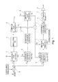
- La
Figure 1 illustre, sous forme de schéma par blocs, les étapes de traitement du procédé de l'invention et leur enchaînement. - La
Figure 2 est un exemple de réponse en fréquence d'un filtre de type lowshelf utilisé dans le traitement selon l'invention. - La
Figure 3 montre la caractéristique de réponse en fréquence d'un haut-parleur de basses de type subwoofer, et l'amélioration qu'il est possible d'obtenir par le traitement de renforcement selon l'invention.
- The
Figure 1 illustrates, in block diagram form, the process steps of the process of the invention and their sequencing. - The
Figure 2 is an example of frequency response of a lowshelf type filter used in the processing according to the invention. - The
Figure 3 shows the frequency response characteristic of a subwoofer-type bass speaker , and the improvement that can be achieved by the reinforcement processing according to the invention.
La
On notera toutefois que, bien que ce schéma soit présenté sous forme de circuits interconnectés, la mise en oeuvre des différentes fonctions est essentiellement logicielle, et cette représentation n'a qu'un caractère illustratif. Le logiciel peut notamment être mis en oeuvre au sein d'une puce dédiée de traitement de signal numérique de type DSP.It will be noted however that, although this diagram is presented in the form of interconnected circuits, the implementation of the various functions is essentially software, and this representation is only of an illustrative nature. The software can in particular be implemented within a dedicated digital signal processing chip of the DSP type.
Dans la mesure où l'algorithme de traitement de l'invention simule le comportement d'un haut-parleur et d'un amplificateur, il utilise des grandeurs physiques réelles (excursion en millimètres, tension en volts, etc.). De ce fait, comme le signal audio à reproduire E appliqué en entrée est un signal sans dimension (par exemple un signal de type PCM qui est le standard le plus courant en audio numérique), il est nécessaire, dans une première étape désignée a, de convertir en termes de tension (volts) ce signal sans dimension E. Cette conversion est effectuée en connaissant le gain G1 de l'amplificateur analogique (étage m sur la figure) qui sera utilisé après le traitement numérique (étages a à k sur la figure), en aval du convertisseur numérique/analogique (étage l sur la figure). G1 correspond à un facteur de conversion lié à la tension de crête obtenue en sortie pour un signal pleine échelle en entrée, avec un gain d'amplification de 0 dB.Since the processing algorithm of the invention simulates the behavior of a loudspeaker and an amplifier, it uses real physical quantities (excursion in millimeters, voltage in volts, etc.). As a result, since the audio signal to be reproduced E input is a dimensionless signal (for example a PCM type signal which is the most common standard in digital audio), it is necessary, in a first step designated a , to convert in terms of voltage (volts) this dimensionless signal E. This conversion is performed knowing the gain G 1 of the analog amplifier (stage m in the figure) which will be used after the digital processing (stages a to k on the figure), downstream of the digital-to-analog converter (stage 1 in the figure). G 1 corresponds to a conversion factor related to the peak voltage obtained at the output for a full-scale input signal, with an amplification gain of 0 dB.
Le signal de tension VE ainsi obtenu est appliqué en entrée à trois chaînes de traitement correspondant respectivement aux étages référencés b-c-d, e-f-g et h-i-i, chacune de ces trois chaînes de traitement comprenant en entrée un filtre de type lowshelf, respectivement b, e et h.The voltage signal V E thus obtained is input to three processing chains respectively corresponding to the stages referenced b - c - d , e - f - g and h - i - i , each of these three processing chains comprising as input a lowshelf type filter, respectively b , e and h .
Inversement, le signal final issu des étapes de traitement b à i fera l'objet, comme on le décrira plus en détail, d'une conversion inverse (étape k) pour obtenir un signal de sortie S sans dimension (signal PCM), appliqué à un convertisseur numérique/analogique (étape l) pilotant un amplificateur de puissance analogique (schématisé par l'étage m).Conversely, the final signal from the processing steps b to i will be subject, as will be described in more detail, to an inverse conversion (step k ) to obtain a dimensionless output signal S (PCM signal), applied. at a digital / analog converter (step l ) driving an analog power amplifier (schematized by the stage m ).
On notera que les traitements des trois chaînes b-c-d, e-f-g et h-j-1 sont exécutés en cascade, c'est-à-dire que le résultat de l'une des chaînes de traitement sert de paramètre d'entrée pour la chaîne suivante : ainsi, le résultat des traitements b-c-d sert de paramètre d'entrée pour le traitement de la chaîne e-f-g, et le résultat des traitements b-c-d et/ou e-f-g sert de paramètre d'entrée pour la chaîne de traitement h-i-i.It should be noted that the treatments of the three chains b - c - d , e - f - g and h - j - 1 are carried out in cascade, ie the result of one of the processing chains serves as the input parameter for the following string: thus, the result of the b - c - d processing serves as an input parameter for processing the string e - f - g , and the result of the b - c - d and / or e - f - g serves as an input parameter for the processing chain h - i - i .
Concrètement, ces traitements sont effectués par des algorithmes de calcul exécutés de façon itérative à la fréquence d'échantillonnage, pour toutes les trames successives de signal (par exemple 1024 échantillons).In concrete terms, these processes are performed by calculation algorithms performed iteratively at the sampling frequency, for all the successive signal frames (for example 1024 samples).
On va maintenant expliciter la manière dont le filtre lowshelf, tel que celui des étages b, e ou h, opère sur le signal qui lui est appliqué en entrée.We will now explain how the lowshelf filter , such as that of stages b , e or h , operates on the signal applied to it as input.
Un tel filtre lowshelf du second ordre présente une caractéristique telle que celle illustrée
Le filtrage appliqué est déterminé par trois paramètres : la fréquence pivot ou "fréquence de coupure" F0, la consigne de gain G et le facteur de qualité Q. Dans l'exemple illustré, le filtre lowshelf possède une fréquence pivot F0 de 45 Hz, ce qui signifie que le signal présentera une amplification à cette fréquence de G = +2 dB, G = +4 dB, G = +8 dB ... selon le réglage du gain G, avec une pente uniforme de part et d'autre de cette fréquence. Vers le haut, la bande passante de ce filtre lowshelf est limitée à une fréquence maximale de 100 Hz par exemple, un gain unité (0 dB) étant appliqué à toutes les fréquences supérieures. Vers le bas, dans les fréquences les plus graves, en-deçà d'une fréquence d'environ 20 Hz dans l'exemple illustré, le gain d'amplification est rendu constant, la caractéristique présentant une forme sensiblement en plateau (shelf).The filtering applied is determined by three parameters: the pivot frequency or "cut-off frequency" F 0 , the gain setpoint G and the quality factor Q. In the illustrated example, the lowshelf filter has a pivot frequency F 0 of 45 Hz, which means that the signal will have an amplification at this frequency of G = +2 dB, G = +4 dB, G = +8 dB ... depending on the G gain setting, with a uniform slope of other than this frequency. Upward , the bandwidth of this lowshelf filter is limited to a maximum frequency of 100 Hz for example, a unity gain (0 dB) being applied to all higher frequencies. Down, in the lowest frequencies, below a frequency of about 20 Hz in the illustrated example, the amplification gain is made constant, the characteristic having a substantially plateau ( shelf ) shape.
Les filtres lowshelf utilisés dans le cadre de l'invention présenteront une fréquence F0 et un facteur de qualité Q constants, et une consigne de gain variable, le gain maximal pour les fréquences les plus basses pouvant atteindre +16 dB à 10 Hz.The lowshelf filters used in the context of the invention will have a frequency F 0 and a quality factor Q constant, and a variable gain setpoint, the maximum gain for the lowest frequencies of up to +16 dB at 10 Hz.
On va maintenant décrire en détail chacune des étapes de traitement correspondant aux étages b à m.We will now describe in detail each of the processing steps corresponding to the stages b to m .
L'étape b correspond à un filtrage lowshelf de gain fixe G2 appliqué au signal de tension VE.Step b corresponds to a fixed gain lowshelf filtering G 2 applied to the voltage signal V E.
Ce gain G2 est un gain fixe, correspondant à la valeur maximum du gain de consigne par lequel sera filtré le signal (par exemple G = +8 dB dans l'exemple illustré
Le signal issu du filtrage b correspond à la tension que l'on appliquerait aux bornes du haut-parleur de l'installation. Le comportement de ce haut-parleur est simulé à l'étape c de manière à délivrer une information x d'excursion mécanique de la membrane en fonction de la tension appliquée à la bobine.The signal from filtering b corresponds to the voltage that would be applied across the loudspeaker of the installation. The behavior of this loudspeaker is simulated in step c so as to deliver information x mechanical excursion of the membrane as a function of the voltage applied to the coil.
La modélisation du fonctionnement d'un haut-parleur a été décrite par de nombreux auteurs, et ne sera pas décrite plus en détail. Cette modélisation décrit le comportement électromécanique et mécano-acoustique des différents éléments du haut-parleur, et permet de connaître l'excursion x de la membrane ainsi que, si besoin, l'intensité i traversant la bobine.The modeling of the operation of a loudspeaker has been described by many authors, and will not be described in more detail. This model describes the behavior electromechanical and mechanical-acoustic different loudspeaker components, and lets you know the excursion x of the membrane and, if necessary, the current i through the coil.
La connaissance de l'excursion x de la membrane permet, à l'étape d, de comparer cette valeur à un seuil déterminé xMAS au-delà duquel on considère l'excursion comme trop importante (risque d'endommagement du haut-parleur, apparition de distorsions, ...). Si le seuil est dépassé, on détermine alors un gain d'atténuation de consigne G3, inférieur à l'unité, qu'il faudrait appliquer afin de réduire le signal pour que l'excursion reste dans la plage autorisée.The knowledge of the excursion x of the membrane makes it possible, in step d , to compare this value with a determined threshold x MAS beyond which the excursion is considered to be too important (risk of damage to the loudspeaker, appearance of distortions, ...). If the threshold is exceeded, then a set attenuation gain G 3 of less than unity is determined which should be applied in order to reduce the signal so that the excursion remains in the authorized range.
Ce premier gain d'atténuation de consigne G3 est utilisé comme paramètre d'entrée de la deuxième chaîne de traitement e-f-g.This first set attenuation gain G 3 is used as the input parameter of the second processing chain e - f - g .
Ainsi, à l'étape e le signal de tension VE (c'est-à-dire le signal qui avait été appliqué en entrée du premier filtre lowshelf de l'étape b) est de nouveau filtré, cette fois-ci par un filtre lowshelf dont le gain est variable : ce gain est à un instant donné la somme d'une valeur de gain fixe G4 (gain propre du lowshelf e) et de l'atténuation éventuelle G3 calculée à l'étape d (atténuation destinée à éviter tout dépassement de l'excursion x de la membrane du haut-parleur). Le gain G4 est typiquement égal à G2, en tous cas il ne doit pas être supérieur à G2.Thus, in step e the voltage signal V E (that is to say the signal which was applied at the input of the first lowshelf filter of step b ) is again filtered, this time by a LowShelf filter whose gain is variable: this gain is at a given time the sum of a fixed gain value G 4 (own gain LowShelf e) and possible mitigation G 3 calculated in step d (for mitigation avoid exceeding the excursion x of the loudspeaker diaphragm). The gain G 4 is typically equal to G 2 , in any case it must not be greater than G 2 .
Le traitement opéré à l'étape suivante f sur le signal délivré par le second filtre lowshelf e est une étape optionnelle de compensation des non-linéarités du haut-parleur. En effet, si l'on a modélisé le comportement du haut-parleur, on est capable de prédire les non-linéarités de ce comportement, et les compenser par un traitement approprié appliqué au signal. Un tel traitement est en soi connu, et pour cette raison on ne le décrira pas plus en détail.The processing performed in the next step f on the signal delivered by the second lowshelf filter e is an optional step of compensating the non-linearities of the loudspeaker. Indeed, if we modeled the behavior of the loudspeaker, one is able to predict the non-linearities of this behavior, and compensate for them by an appropriate treatment applied to the signal. Such treatment is in itself known, and for this reason it will not be described in more detail.
La valeur du signal délivré par le filtre lowshelf e, éventuellement compensée des non-linéarités par le traitement de l'étape f, est comparée à une valeur vMAX inférieure ou égale, de préférence strictement inférieure, à la tension maximale admissible sur l'amplificateur (étape g). Si la tension calculée par la chaîne de traitement e-f vient à dépasser ce seuil, alors un gain d'atténuation de consigne G5 est calculé, correspondant à l'atténuation qu'il serait nécessaire d'appliquer au signal en entrée pour éviter toute saturation ou écrêtage audio sur l'amplificateur analogique lors de l'amplification du signal. Cette comparaison et le calcul du gain G5 correspondant sont effectués de la même manière qu' à l'étape d pour l'excursion maximale xMAX et le calcul du gain respectif G3.The value of the signal delivered by the lowshelf filter e , possibly compensated for nonlinearities by the processing of step f , is compared with a value v MAX which is less than or equal to, preferably less than, the maximum permissible voltage on the amplifier (step g). If the voltage calculated by the processing chain e - f exceeds this threshold, then a set attenuation gain G 5 is calculated, corresponding to the attenuation that it would be necessary to apply to the input signal to avoid any audio saturation or clipping on the analog amplifier when amplifying the signal. This comparison and the calculation of the corresponding gain G 5 are performed in the same way as in step d for the maximum excursion x MAX and the calculation of the respective gain G 3 .
On notera que la compensation optionnelle des non-linéarités de l'étape f est opérée en amont de l'étage g, car le traitement de compensation des non-linéarités a généralement tendance à augmenter la tension du signal, et doit donc être pris en compte pour vérifier que le signal compensé des non-linéarités ne dépasse pas la limite admissible vMAX. It will be noted that the optional compensation of the non-linearities of step f is carried out upstream of stage g, since the compensation processing of non-linearities generally tends to increase the signal voltage, and must therefore be taken into account. to check that the compensated signal of non-linearities does not exceed the permissible limit v MAX .
Les deux chaînes de traitement b-c-d et e-f-g (ou e-g) ont ainsi permis de déterminer deux gains d'atténuation de consigne respectifs éventuels G3 et G5 pour éviter tout dépassement de l'excursion x et de la tension d'amplification, par rapport aux maxima admissibles respectifs.The two processing chains b - c - d and e - f - g (or e - g ) have thus made it possible to determine two respective potential set - point savings G 3 and G 5 in order to avoid exceeding the excursion x and the amplification voltage, relative to the respective allowable maxima.
Les gains G3 et/ou G5 ainsi éventuellement calculés sont utilisés comme paramètres d'entrée pour la troisième chaîne de traitement h-i-i.The gains G 3 and / or G 5 thus possibly calculated are used as input parameters for the third processing chain h - i - i .
Cette chaîne de traitement comprend un filtrage lowshelf variable h recevant en entrée le signal VE, c'est-à-dire le même signal que celui qui était appliqué aux étages de filtrage b et e précédemment exposés.This processing chain comprises a variable lowshelf filter h receiving as input the signal V E , that is to say the same signal that was applied to the filtering stages b and e previously exposed.
Le gain appliqué à l'étape h est un gain variable, comprenant à un instant donné un gain fixe G6 (gain propre du lowshelf h), éventuellement corrigé d'une atténuation correspondant au gain de consigne G3 ou G5, ou doublement corrigé par les atténuations cumulées G3+G5. Typiquement, on aura G6 = G4 = G2, en tout état de cause G4 et G6 ne devront pas être supérieurs à G2.The gain applied in step h is a variable gain, comprising at a given instant a fixed gain G 6 (eigen gain of lowshelf h ), possibly corrected by an attenuation corresponding to the set gain G 3 or G 5 , or doubling corrected by cumulative attenuations G 3 + G 5 . Typically, we will have G 6 = G 4 = G 2 , in any case G 4 and G 6 must not be greater than G 2 .
Le signal résultant fait l'objet du traitement suivant (étape i) qui est opéré par un étage limiteur de tension de type classique, agissant sur toutes les composantes du signal (et pas seulement sur les composantes graves comme dans le cas d'un filtrage lowshelf) : si la tension appliquée en entrée dépasse la tension maximale admissible v'MAX de l'amplificateur, alors un gain atténuateur G7 est appliqué au signal ; dans le cas contraire, aucune limitation n'est appliquée et le signal est transmis tel quel aux étages aval.The resulting signal is the subject of the following processing (step i ) which is operated by a conventional voltage limiter stage, acting on all the signal components (and not only on the serious components as in the case of a filtering lowshelf ): if the input voltage exceeds the maximum allowable voltage v ' MAX of the amplifier, then an attenuator gain G 7 is applied to the signal; in the opposite case, no limitation is applied and the signal is transmitted as such to the downstream stages.
La limitation opérée par l'étage i est nécessaire dans le cas où le dépassement de la tension au-delà du seuil v'MAX ne serait pas dû au signal des basses fréquences renforcé par le filtre lowshelf h, mais par exemple par un gain d'amplification élevé demandé par l'utilisateur du système faisant dépasser le signal audio au-delà de la dynamique acceptée par l'amplificateur.The limitation made by the stage i is necessary in the case where the exceeding of the voltage beyond the threshold v ' MAX is not due to the signal of the low frequencies reinforced by the lowshelf filter h, but for example by a gain of high amplification requested by the user of the system causing the audio signal to exceed the dynamic range accepted by the amplifier.
En aval des étages h et i peut être prévu, optionnellement, un étage i de compensation des non-linéarités, d'un type comparable à l'étage f précédemment décrit.Downstream of the stages h and i may be provided, optionally, a compensation stage i of the non-linearities, of a type comparable to the stage f previously described.
On notera cependant que, si le signal entrant dans cet étage i a été atténué par l'effet du limiteur de l'étage amont i, alors le calcul de la loi de contrôle de la compensation des non-linéarités est désactivé et l'étage i se contente de transmettre le signal sans le modifier. En effet, le processus de limitation pleine bande de l'étage i introduit, par nature, des distorsions et il n'est pas utile, voire néfaste, de tenter d'annuler les distorsions d'un système dans le cas d'un signal de ce type.Note however that, if the signal entering this stage i has been attenuated by the effect of the limiter of the upstream stage i , then the calculation of the control law of the compensation of the non-linearities is deactivated and the stage i merely transmits the signal without modifying it. Indeed, the process of limiting full-band stage i introduces, by nature, distortions and it is not useful, even harmful, to try to cancel the distortions of a system in the case of a signal of that type.
Il est à noter que l'étage i de compensation des non-linéarités est susceptible d'ajouter de la puissance au signal de tension final VS obtenu en sortie. Aussi, il est nécessaire que l'étage limiteur i précédant cet étage i opère par rapport à un seuil v'MAX prenant en compte une marge suffisante par rapport à la tension maximale vMAX susceptible d'être délivrée par l'amplificateur audio, si l'option de compensation des non-linéarités de l'étage i est activée.It should be noted that the compensation stage i of the non-linearities is capable of adding power to the final voltage signal V S obtained at the output. Also, it is necessary that the limiting stage i preceding this stage i operates with respect to a threshold v ' MAX taking into account a sufficient margin with respect to the maximum voltage v MAX likely to be delivered by the audio amplifier, if the nonlinearity compensation option of stage i is activated.
Le signal de tension VS finalement obtenu (valeur en volts) fait ensuite l'objet d'une conversion inverse, à l'étage k, en un signal de sortie S sans dimension, par exemple de type signal numérique PCM, en divisant le signal VS par le gain d'amplification.Finally, the voltage signal V S finally obtained (value in volts) is inversely converted, at stage k , into a dimensionless output signal S, for example of the PCM digital signal type, by dividing the V S signal by the amplification gain.
Le signal ainsi obtenu peut être alors reproduit, après conversion numérique/analogique (étage l) et amplification finale de puissance (étage m).The signal thus obtained can then be reproduced, after digital / analog conversion (stage l ) and final power amplification (stage m ).
Le résultat obtenu est par exemple celui illustré
- ni d'endommagement de la membrane du fait d'une excursion excessive,
- ni d'écrêtage ou de saturation de l'amplificateur du fait de la puissance accrue restituée dans le registre grave,
- ni d'introduction d'aucune distorsion,
- no damage to the membrane due to excessive excursion,
- neither clipping nor saturation of the amplifier because of the increased power restored in the low register,
- nor introduction of any distortion,
Claims (7)
caractérisé en ce qu'il comprend les étapes de traitement successives suivantes :
characterized in that it comprises the following successive processing steps:
Applications Claiming Priority (1)
| Application Number | Priority Date | Filing Date | Title |
|---|---|---|---|
| FR1158164A FR2980070B1 (en) | 2011-09-13 | 2011-09-13 | METHOD OF REINFORCING SERIOUS FREQUENCIES IN A DIGITAL AUDIO SIGNAL. |
Publications (2)
| Publication Number | Publication Date |
|---|---|
| EP2571286A1 true EP2571286A1 (en) | 2013-03-20 |
| EP2571286B1 EP2571286B1 (en) | 2015-03-04 |
Family
ID=46704556
Family Applications (1)
| Application Number | Title | Priority Date | Filing Date |
|---|---|---|---|
| EP12182044.3A Not-in-force EP2571286B1 (en) | 2011-09-13 | 2012-08-28 | Method for reinforcing the bass frequencies in a digital audio signal |
Country Status (4)
| Country | Link |
|---|---|
| US (1) | US9048799B2 (en) |
| EP (1) | EP2571286B1 (en) |
| CN (1) | CN103002381A (en) |
| FR (1) | FR2980070B1 (en) |
Cited By (1)
| Publication number | Priority date | Publication date | Assignee | Title |
|---|---|---|---|---|
| FR3139262A1 (en) | 2022-08-23 | 2024-03-01 | Faurecia Clarion Electronics Europe | Digital audio signal processing method and system for improving the rendering of low frequencies |
Families Citing this family (12)
| Publication number | Priority date | Publication date | Assignee | Title |
|---|---|---|---|---|
| US9247342B2 (en) | 2013-05-14 | 2016-01-26 | James J. Croft, III | Loudspeaker enclosure system with signal processor for enhanced perception of low frequency output |
| CN105916079B (en) * | 2016-06-07 | 2019-09-13 | 瑞声科技(新加坡)有限公司 | A kind of nonlinear loudspeaker compensation method and device |
| US10911869B2 (en) | 2017-04-19 | 2021-02-02 | Dolby Laboratories Licensing Corporation | Variable-frequency sliding band equalization for controlling sealed loudspeaker excursion |
| WO2018194990A1 (en) * | 2017-04-19 | 2018-10-25 | Dolby Laboratories Licensing Corporation | Variable-frequency sliding band equalization for controlling sealed loudspeaker excursion |
| US10200003B1 (en) * | 2017-10-03 | 2019-02-05 | Google Llc | Dynamically extending loudspeaker capabilities |
| CN110149576B (en) * | 2018-02-13 | 2021-07-06 | 易音特电子株式会社 | Wearable acoustic transducer |
| JP6939660B2 (en) * | 2018-03-13 | 2021-09-22 | トヨタ自動車株式会社 | Vehicle driving control system |
| WO2019232278A1 (en) * | 2018-05-30 | 2019-12-05 | Magic Leap, Inc. | Index scheming for filter parameters |
| LU100989B1 (en) * | 2018-11-12 | 2020-05-12 | Hochschule Duesseldorf | Method for improving sound reproduction of low frequencies and apparatus therefore |
| US10771893B1 (en) * | 2019-10-10 | 2020-09-08 | xMEMS Labs, Inc. | Sound producing apparatus |
| CN114143866B (en) * | 2020-09-04 | 2023-08-15 | 成都鼎桥通信技术有限公司 | Method, device and storage medium for preventing saturation of receiver uplink |
| CN115442709B (en) * | 2022-07-29 | 2023-06-16 | 荣耀终端有限公司 | Audio processing method, virtual bass enhancement system, device, and storage medium |
Citations (7)
| Publication number | Priority date | Publication date | Assignee | Title |
|---|---|---|---|---|
| US4327250A (en) | 1979-05-03 | 1982-04-27 | Electro Audio Dynamics Inc. | Dynamic speaker equalizer |
| US6201873B1 (en) | 1998-06-08 | 2001-03-13 | Nortel Networks Limited | Loudspeaker-dependent audio compression |
| US20050207584A1 (en) | 2004-03-19 | 2005-09-22 | Andrew Bright | System for limiting loudspeaker displacement |
| EP1799013A1 (en) | 2005-12-14 | 2007-06-20 | Harman/Becker Automotive Systems GmbH | Method and system for predicting the behavior of a transducer |
| US20080175397A1 (en) | 2007-01-23 | 2008-07-24 | Holman Tomlinson | Low-frequency range extension and protection system for loudspeakers |
| WO2008139047A2 (en) | 2007-04-12 | 2008-11-20 | Parrot | Active acoustic housing with multiple transducer distributed mode loudspeaker |
| EP2113913A1 (en) | 2008-04-29 | 2009-11-04 | Parrot | Method and system for reconstituting low frequencies in an audio signal |
Family Cites Families (6)
| Publication number | Priority date | Publication date | Assignee | Title |
|---|---|---|---|---|
| US20050271216A1 (en) * | 2004-06-04 | 2005-12-08 | Khosrow Lashkari | Method and apparatus for loudspeaker equalization |
| US8284955B2 (en) * | 2006-02-07 | 2012-10-09 | Bongiovi Acoustics Llc | System and method for digital signal processing |
| US8462963B2 (en) * | 2004-08-10 | 2013-06-11 | Bongiovi Acoustics, LLCC | System and method for processing audio signal |
| WO2007092420A2 (en) * | 2006-02-07 | 2007-08-16 | Anthony Bongiovi | Collapsible speaker and headliner |
| US8750538B2 (en) * | 2006-05-05 | 2014-06-10 | Creative Technology Ltd | Method for enhancing audio signals |
| US8855322B2 (en) * | 2011-01-12 | 2014-10-07 | Qualcomm Incorporated | Loudness maximization with constrained loudspeaker excursion |
-
2011
- 2011-09-13 FR FR1158164A patent/FR2980070B1/en not_active Expired - Fee Related
-
2012
- 2012-08-28 EP EP12182044.3A patent/EP2571286B1/en not_active Not-in-force
- 2012-08-28 US US13/597,193 patent/US9048799B2/en not_active Expired - Fee Related
- 2012-09-12 CN CN2012103372632A patent/CN103002381A/en active Pending
Patent Citations (7)
| Publication number | Priority date | Publication date | Assignee | Title |
|---|---|---|---|---|
| US4327250A (en) | 1979-05-03 | 1982-04-27 | Electro Audio Dynamics Inc. | Dynamic speaker equalizer |
| US6201873B1 (en) | 1998-06-08 | 2001-03-13 | Nortel Networks Limited | Loudspeaker-dependent audio compression |
| US20050207584A1 (en) | 2004-03-19 | 2005-09-22 | Andrew Bright | System for limiting loudspeaker displacement |
| EP1799013A1 (en) | 2005-12-14 | 2007-06-20 | Harman/Becker Automotive Systems GmbH | Method and system for predicting the behavior of a transducer |
| US20080175397A1 (en) | 2007-01-23 | 2008-07-24 | Holman Tomlinson | Low-frequency range extension and protection system for loudspeakers |
| WO2008139047A2 (en) | 2007-04-12 | 2008-11-20 | Parrot | Active acoustic housing with multiple transducer distributed mode loudspeaker |
| EP2113913A1 (en) | 2008-04-29 | 2009-11-04 | Parrot | Method and system for reconstituting low frequencies in an audio signal |
Cited By (1)
| Publication number | Priority date | Publication date | Assignee | Title |
|---|---|---|---|---|
| FR3139262A1 (en) | 2022-08-23 | 2024-03-01 | Faurecia Clarion Electronics Europe | Digital audio signal processing method and system for improving the rendering of low frequencies |
Also Published As
| Publication number | Publication date |
|---|---|
| CN103002381A (en) | 2013-03-27 |
| FR2980070A1 (en) | 2013-03-15 |
| US9048799B2 (en) | 2015-06-02 |
| FR2980070B1 (en) | 2013-11-15 |
| US20130230191A1 (en) | 2013-09-05 |
| EP2571286B1 (en) | 2015-03-04 |
Similar Documents
| Publication | Publication Date | Title |
|---|---|---|
| EP2571286B1 (en) | Method for reinforcing the bass frequencies in a digital audio signal | |
| CA2628524C (en) | Sound tuning method | |
| EP2695394B1 (en) | Integrated psychoacoustic bass enhancement (pbe) for improved audio | |
| US20110169721A1 (en) | Upstream signal processing for client devices in a small-cell wireless network | |
| JP2005530432A (en) | Method for digital equalization of sound from loudspeakers in a room and use of this method | |
| US9948261B2 (en) | Method and apparatus to equalize acoustic response of a speaker system using multi-rate FIR and all-pass IIR filters | |
| EP2930942A1 (en) | Audio headset with active noise control (anc) with electric hiss reduction | |
| EP2113913B1 (en) | Method and system for reconstituting low frequencies in an audio signal | |
| EP2920880A1 (en) | Audio loudness control system | |
| KR20160113224A (en) | An audio compression system for compressing an audio signal | |
| KR20140055932A (en) | Apparatus and method for keeping output loudness and quality of sound among differernt equalizer modes | |
| US8254590B2 (en) | System and method for intelligibility enhancement of audio information | |
| Künzel et al. | Forensic automatic speaker recognition with degraded and enhanced speech | |
| EP3637792B1 (en) | Device for controlling a speaker and associated sound playback system | |
| JP7352383B2 (en) | Mixing processing device and mixing processing method | |
| US20230029841A1 (en) | Perceptual bass extension with loudness management and artificial intelligence (ai) | |
| FR3073694A1 (en) | METHOD FOR LIVE SOUNDING, IN THE HELMET, TAKING INTO ACCOUNT AUDITIVE PERCEPTION CHARACTERISTICS OF THE AUDITOR | |
| CA3163814A1 (en) | Method and associated device for transforming characteristics of an audio signal | |
| FR3091079A1 (en) | DEVICE FOR CONTROLLING THE DYNAMICS OF A HIGH FIDELITY CHAIN AND FOR ADAPTING THE SPECTRAL RESPONSE OF AN ACOUSTIC SPEAKER | |
| WO2023135232A1 (en) | Method for managing the low frequencies of a loudspeaker and device for implementing said method | |
| FR3087075A1 (en) | DEVICE FOR COMPENSATING FOR FREQUENCY PERCEPTION DIFFERENCES IN AN AUDIO SIGNAL AS A FUNCTION OF THE SOUND LEVEL OF SIGNAL RENDERING | |
| Minnaar | Non-linear signal processing for low frequency enhancement | |
| Behler et al. | A Loudspeaker Management System With FIR/IIR Filtering | |
| FR3067510A1 (en) | SEMICONDUCTOR AMPLITUDE MODULATION CIRCUIT | |
| FR2808154A1 (en) | BELL-FREE MOBILE TELEPHONE |
Legal Events
| Date | Code | Title | Description |
|---|---|---|---|
| PUAI | Public reference made under article 153(3) epc to a published international application that has entered the european phase |
Free format text: ORIGINAL CODE: 0009012 |
|
| AK | Designated contracting states |
Kind code of ref document: A1 Designated state(s): AL AT BE BG CH CY CZ DE DK EE ES FI FR GB GR HR HU IE IS IT LI LT LU LV MC MK MT NL NO PL PT RO RS SE SI SK SM TR |
|
| AX | Request for extension of the european patent |
Extension state: BA ME |
|
| 17P | Request for examination filed |
Effective date: 20130704 |
|
| RBV | Designated contracting states (corrected) |
Designated state(s): AL AT BE BG CH CY CZ DE DK EE ES FI FR GB GR HR HU IE IS IT LI LT LU LV MC MK MT NL NO PL PT RO RS SE SI SK SM TR |
|
| RIC1 | Information provided on ipc code assigned before grant |
Ipc: H04R 3/00 20060101ALN20140710BHEP Ipc: H04R 3/04 20060101AFI20140710BHEP Ipc: H04R 3/08 20060101ALI20140710BHEP Ipc: H03G 3/00 20060101ALI20140710BHEP |
|
| GRAP | Despatch of communication of intention to grant a patent |
Free format text: ORIGINAL CODE: EPIDOSNIGR1 |
|
| INTG | Intention to grant announced |
Effective date: 20141006 |
|
| GRAS | Grant fee paid |
Free format text: ORIGINAL CODE: EPIDOSNIGR3 |
|
| GRAA | (expected) grant |
Free format text: ORIGINAL CODE: 0009210 |
|
| AK | Designated contracting states |
Kind code of ref document: B1 Designated state(s): AL AT BE BG CH CY CZ DE DK EE ES FI FR GB GR HR HU IE IS IT LI LT LU LV MC MK MT NL NO PL PT RO RS SE SI SK SM TR |
|
| REG | Reference to a national code |
Ref country code: GB Ref legal event code: FG4D Free format text: NOT ENGLISH |
|
| REG | Reference to a national code |
Ref country code: CH Ref legal event code: EP |
|
| REG | Reference to a national code |
Ref country code: IE Ref legal event code: FG4D Free format text: LANGUAGE OF EP DOCUMENT: FRENCH |
|
| REG | Reference to a national code |
Ref country code: AT Ref legal event code: REF Ref document number: 714735 Country of ref document: AT Kind code of ref document: T Effective date: 20150415 |
|
| REG | Reference to a national code |
Ref country code: DE Ref legal event code: R096 Ref document number: 602012005519 Country of ref document: DE Effective date: 20150416 |
|
| REG | Reference to a national code |
Ref country code: NL Ref legal event code: T3 |
|
| REG | Reference to a national code |
Ref country code: AT Ref legal event code: MK05 Ref document number: 714735 Country of ref document: AT Kind code of ref document: T Effective date: 20150304 |
|
| PG25 | Lapsed in a contracting state [announced via postgrant information from national office to epo] |
Ref country code: FI Free format text: LAPSE BECAUSE OF FAILURE TO SUBMIT A TRANSLATION OF THE DESCRIPTION OR TO PAY THE FEE WITHIN THE PRESCRIBED TIME-LIMIT Effective date: 20150304 Ref country code: NO Free format text: LAPSE BECAUSE OF FAILURE TO SUBMIT A TRANSLATION OF THE DESCRIPTION OR TO PAY THE FEE WITHIN THE PRESCRIBED TIME-LIMIT Effective date: 20150604 Ref country code: SE Free format text: LAPSE BECAUSE OF FAILURE TO SUBMIT A TRANSLATION OF THE DESCRIPTION OR TO PAY THE FEE WITHIN THE PRESCRIBED TIME-LIMIT Effective date: 20150304 Ref country code: ES Free format text: LAPSE BECAUSE OF FAILURE TO SUBMIT A TRANSLATION OF THE DESCRIPTION OR TO PAY THE FEE WITHIN THE PRESCRIBED TIME-LIMIT Effective date: 20150304 Ref country code: LT Free format text: LAPSE BECAUSE OF FAILURE TO SUBMIT A TRANSLATION OF THE DESCRIPTION OR TO PAY THE FEE WITHIN THE PRESCRIBED TIME-LIMIT Effective date: 20150304 Ref country code: HR Free format text: LAPSE BECAUSE OF FAILURE TO SUBMIT A TRANSLATION OF THE DESCRIPTION OR TO PAY THE FEE WITHIN THE PRESCRIBED TIME-LIMIT Effective date: 20150304 |
|
| REG | Reference to a national code |
Ref country code: LT Ref legal event code: MG4D |
|
| PG25 | Lapsed in a contracting state [announced via postgrant information from national office to epo] |
Ref country code: AT Free format text: LAPSE BECAUSE OF FAILURE TO SUBMIT A TRANSLATION OF THE DESCRIPTION OR TO PAY THE FEE WITHIN THE PRESCRIBED TIME-LIMIT Effective date: 20150304 Ref country code: RS Free format text: LAPSE BECAUSE OF FAILURE TO SUBMIT A TRANSLATION OF THE DESCRIPTION OR TO PAY THE FEE WITHIN THE PRESCRIBED TIME-LIMIT Effective date: 20150304 Ref country code: GR Free format text: LAPSE BECAUSE OF FAILURE TO SUBMIT A TRANSLATION OF THE DESCRIPTION OR TO PAY THE FEE WITHIN THE PRESCRIBED TIME-LIMIT Effective date: 20150605 Ref country code: LV Free format text: LAPSE BECAUSE OF FAILURE TO SUBMIT A TRANSLATION OF THE DESCRIPTION OR TO PAY THE FEE WITHIN THE PRESCRIBED TIME-LIMIT Effective date: 20150304 |
|
| REG | Reference to a national code |
Ref country code: FR Ref legal event code: PLFP Year of fee payment: 4 |
|
| PG25 | Lapsed in a contracting state [announced via postgrant information from national office to epo] |
Ref country code: CZ Free format text: LAPSE BECAUSE OF FAILURE TO SUBMIT A TRANSLATION OF THE DESCRIPTION OR TO PAY THE FEE WITHIN THE PRESCRIBED TIME-LIMIT Effective date: 20150304 Ref country code: EE Free format text: LAPSE BECAUSE OF FAILURE TO SUBMIT A TRANSLATION OF THE DESCRIPTION OR TO PAY THE FEE WITHIN THE PRESCRIBED TIME-LIMIT Effective date: 20150304 Ref country code: PT Free format text: LAPSE BECAUSE OF FAILURE TO SUBMIT A TRANSLATION OF THE DESCRIPTION OR TO PAY THE FEE WITHIN THE PRESCRIBED TIME-LIMIT Effective date: 20150706 Ref country code: RO Free format text: LAPSE BECAUSE OF FAILURE TO SUBMIT A TRANSLATION OF THE DESCRIPTION OR TO PAY THE FEE WITHIN THE PRESCRIBED TIME-LIMIT Effective date: 20150304 Ref country code: SK Free format text: LAPSE BECAUSE OF FAILURE TO SUBMIT A TRANSLATION OF THE DESCRIPTION OR TO PAY THE FEE WITHIN THE PRESCRIBED TIME-LIMIT Effective date: 20150304 |
|
| PG25 | Lapsed in a contracting state [announced via postgrant information from national office to epo] |
Ref country code: PL Free format text: LAPSE BECAUSE OF FAILURE TO SUBMIT A TRANSLATION OF THE DESCRIPTION OR TO PAY THE FEE WITHIN THE PRESCRIBED TIME-LIMIT Effective date: 20150304 Ref country code: IS Free format text: LAPSE BECAUSE OF FAILURE TO SUBMIT A TRANSLATION OF THE DESCRIPTION OR TO PAY THE FEE WITHIN THE PRESCRIBED TIME-LIMIT Effective date: 20150704 |
|
| REG | Reference to a national code |
Ref country code: DE Ref legal event code: R097 Ref document number: 602012005519 Country of ref document: DE |
|
| PLBE | No opposition filed within time limit |
Free format text: ORIGINAL CODE: 0009261 |
|
| STAA | Information on the status of an ep patent application or granted ep patent |
Free format text: STATUS: NO OPPOSITION FILED WITHIN TIME LIMIT |
|
| PG25 | Lapsed in a contracting state [announced via postgrant information from national office to epo] |
Ref country code: DK Free format text: LAPSE BECAUSE OF FAILURE TO SUBMIT A TRANSLATION OF THE DESCRIPTION OR TO PAY THE FEE WITHIN THE PRESCRIBED TIME-LIMIT Effective date: 20150304 |
|
| 26N | No opposition filed |
Effective date: 20151207 |
|
| PG25 | Lapsed in a contracting state [announced via postgrant information from national office to epo] |
Ref country code: SI Free format text: LAPSE BECAUSE OF FAILURE TO SUBMIT A TRANSLATION OF THE DESCRIPTION OR TO PAY THE FEE WITHIN THE PRESCRIBED TIME-LIMIT Effective date: 20150304 |
|
| PG25 | Lapsed in a contracting state [announced via postgrant information from national office to epo] |
Ref country code: MC Free format text: LAPSE BECAUSE OF FAILURE TO SUBMIT A TRANSLATION OF THE DESCRIPTION OR TO PAY THE FEE WITHIN THE PRESCRIBED TIME-LIMIT Effective date: 20150304 Ref country code: LU Free format text: LAPSE BECAUSE OF FAILURE TO SUBMIT A TRANSLATION OF THE DESCRIPTION OR TO PAY THE FEE WITHIN THE PRESCRIBED TIME-LIMIT Effective date: 20150828 |
|
| REG | Reference to a national code |
Ref country code: CH Ref legal event code: PL |
|
| PG25 | Lapsed in a contracting state [announced via postgrant information from national office to epo] |
Ref country code: CH Free format text: LAPSE BECAUSE OF NON-PAYMENT OF DUE FEES Effective date: 20150831 Ref country code: LI Free format text: LAPSE BECAUSE OF NON-PAYMENT OF DUE FEES Effective date: 20150831 |
|
| REG | Reference to a national code |
Ref country code: IE Ref legal event code: MM4A |
|
| REG | Reference to a national code |
Ref country code: DE Ref legal event code: R081 Ref document number: 602012005519 Country of ref document: DE Owner name: PARROT DRONES, FR Free format text: FORMER OWNER: PARROT, PARIS, FR |
|
| PG25 | Lapsed in a contracting state [announced via postgrant information from national office to epo] |
Ref country code: IE Free format text: LAPSE BECAUSE OF NON-PAYMENT OF DUE FEES Effective date: 20150828 |
|
| REG | Reference to a national code |
Ref country code: FR Ref legal event code: PLFP Year of fee payment: 5 |
|
| REG | Reference to a national code |
Ref country code: GB Ref legal event code: 732E Free format text: REGISTERED BETWEEN 20160811 AND 20160817 |
|
| PGFP | Annual fee paid to national office [announced via postgrant information from national office to epo] |
Ref country code: NL Payment date: 20160824 Year of fee payment: 5 |
|
| REG | Reference to a national code |
Ref country code: NL Ref legal event code: PD Owner name: PARROT DRONES; FR Free format text: DETAILS ASSIGNMENT: VERANDERING VAN EIGENAAR(S), OVERDRACHT; FORMER OWNER NAME: PARROT Effective date: 20160804 |
|
| PGFP | Annual fee paid to national office [announced via postgrant information from national office to epo] |
Ref country code: DE Payment date: 20160823 Year of fee payment: 5 Ref country code: IT Payment date: 20160823 Year of fee payment: 5 Ref country code: GB Payment date: 20160824 Year of fee payment: 5 |
|
| REG | Reference to a national code |
Ref country code: FR Ref legal event code: TP Owner name: PARROT DRONES, FR Effective date: 20161010 |
|
| PGFP | Annual fee paid to national office [announced via postgrant information from national office to epo] |
Ref country code: FR Payment date: 20160829 Year of fee payment: 5 |
|
| PG25 | Lapsed in a contracting state [announced via postgrant information from national office to epo] |
Ref country code: MT Free format text: LAPSE BECAUSE OF FAILURE TO SUBMIT A TRANSLATION OF THE DESCRIPTION OR TO PAY THE FEE WITHIN THE PRESCRIBED TIME-LIMIT Effective date: 20150304 |
|
| PG25 | Lapsed in a contracting state [announced via postgrant information from national office to epo] |
Ref country code: SM Free format text: LAPSE BECAUSE OF FAILURE TO SUBMIT A TRANSLATION OF THE DESCRIPTION OR TO PAY THE FEE WITHIN THE PRESCRIBED TIME-LIMIT Effective date: 20150304 Ref country code: BG Free format text: LAPSE BECAUSE OF FAILURE TO SUBMIT A TRANSLATION OF THE DESCRIPTION OR TO PAY THE FEE WITHIN THE PRESCRIBED TIME-LIMIT Effective date: 20150304 Ref country code: HU Free format text: LAPSE BECAUSE OF FAILURE TO SUBMIT A TRANSLATION OF THE DESCRIPTION OR TO PAY THE FEE WITHIN THE PRESCRIBED TIME-LIMIT; INVALID AB INITIO Effective date: 20120828 |
|
| PG25 | Lapsed in a contracting state [announced via postgrant information from national office to epo] |
Ref country code: CY Free format text: LAPSE BECAUSE OF FAILURE TO SUBMIT A TRANSLATION OF THE DESCRIPTION OR TO PAY THE FEE WITHIN THE PRESCRIBED TIME-LIMIT Effective date: 20150304 |
|
| PG25 | Lapsed in a contracting state [announced via postgrant information from national office to epo] |
Ref country code: BE Free format text: LAPSE BECAUSE OF NON-PAYMENT OF DUE FEES Effective date: 20150831 |
|
| PG25 | Lapsed in a contracting state [announced via postgrant information from national office to epo] |
Ref country code: TR Free format text: LAPSE BECAUSE OF FAILURE TO SUBMIT A TRANSLATION OF THE DESCRIPTION OR TO PAY THE FEE WITHIN THE PRESCRIBED TIME-LIMIT Effective date: 20150304 |
|
| REG | Reference to a national code |
Ref country code: DE Ref legal event code: R119 Ref document number: 602012005519 Country of ref document: DE |
|
| REG | Reference to a national code |
Ref country code: NL Ref legal event code: MM Effective date: 20170901 |
|
| GBPC | Gb: european patent ceased through non-payment of renewal fee |
Effective date: 20170828 |
|
| REG | Reference to a national code |
Ref country code: FR Ref legal event code: ST Effective date: 20180430 |
|
| PG25 | Lapsed in a contracting state [announced via postgrant information from national office to epo] |
Ref country code: NL Free format text: LAPSE BECAUSE OF NON-PAYMENT OF DUE FEES Effective date: 20170901 Ref country code: MK Free format text: LAPSE BECAUSE OF FAILURE TO SUBMIT A TRANSLATION OF THE DESCRIPTION OR TO PAY THE FEE WITHIN THE PRESCRIBED TIME-LIMIT Effective date: 20150304 |
|
| PG25 | Lapsed in a contracting state [announced via postgrant information from national office to epo] |
Ref country code: DE Free format text: LAPSE BECAUSE OF NON-PAYMENT OF DUE FEES Effective date: 20180301 Ref country code: GB Free format text: LAPSE BECAUSE OF NON-PAYMENT OF DUE FEES Effective date: 20170828 |
|
| PG25 | Lapsed in a contracting state [announced via postgrant information from national office to epo] |
Ref country code: IT Free format text: LAPSE BECAUSE OF NON-PAYMENT OF DUE FEES Effective date: 20170828 Ref country code: FR Free format text: LAPSE BECAUSE OF NON-PAYMENT OF DUE FEES Effective date: 20170831 |
|
| PG25 | Lapsed in a contracting state [announced via postgrant information from national office to epo] |
Ref country code: AL Free format text: LAPSE BECAUSE OF FAILURE TO SUBMIT A TRANSLATION OF THE DESCRIPTION OR TO PAY THE FEE WITHIN THE PRESCRIBED TIME-LIMIT Effective date: 20150304 |