EP2571199B1 - Method and apparatus for assessing the quality of a communication channel in a multi-domain network - Google Patents
Method and apparatus for assessing the quality of a communication channel in a multi-domain network Download PDFInfo
- Publication number
- EP2571199B1 EP2571199B1 EP20110306176 EP11306176A EP2571199B1 EP 2571199 B1 EP2571199 B1 EP 2571199B1 EP 20110306176 EP20110306176 EP 20110306176 EP 11306176 A EP11306176 A EP 11306176A EP 2571199 B1 EP2571199 B1 EP 2571199B1
- Authority
- EP
- European Patent Office
- Prior art keywords
- probe
- signal
- probe signal
- communication
- feedback signal
- Prior art date
- Legal status (The legal status is an assumption and is not a legal conclusion. Google has not performed a legal analysis and makes no representation as to the accuracy of the status listed.)
- Active
Links
- 230000006854 communication Effects 0.000 title claims description 37
- 238000004891 communication Methods 0.000 title claims description 37
- 238000000034 method Methods 0.000 title claims description 26
- 239000000523 sample Substances 0.000 claims description 95
- 125000004122 cyclic group Chemical group 0.000 claims description 26
- 230000005540 biological transmission Effects 0.000 claims description 22
- 238000001914 filtration Methods 0.000 claims description 10
- 238000000926 separation method Methods 0.000 claims description 8
- 230000003595 spectral effect Effects 0.000 claims description 6
- 230000002123 temporal effect Effects 0.000 claims description 6
- 238000004590 computer program Methods 0.000 claims description 2
- 239000003795 chemical substances by application Substances 0.000 description 13
- 230000006870 function Effects 0.000 description 6
- 238000001228 spectrum Methods 0.000 description 6
- 230000003993 interaction Effects 0.000 description 4
- 230000015654 memory Effects 0.000 description 4
- 230000007175 bidirectional communication Effects 0.000 description 3
- 230000015572 biosynthetic process Effects 0.000 description 3
- 230000007246 mechanism Effects 0.000 description 3
- 230000011664 signaling Effects 0.000 description 3
- 230000002457 bidirectional effect Effects 0.000 description 2
- 238000013500 data storage Methods 0.000 description 2
- 230000008054 signal transmission Effects 0.000 description 2
- RYGMFSIKBFXOCR-UHFFFAOYSA-N Copper Chemical compound [Cu] RYGMFSIKBFXOCR-UHFFFAOYSA-N 0.000 description 1
- 230000001427 coherent effect Effects 0.000 description 1
- 229910052802 copper Inorganic materials 0.000 description 1
- 239000010949 copper Substances 0.000 description 1
- 230000001934 delay Effects 0.000 description 1
- 230000003111 delayed effect Effects 0.000 description 1
- 238000009795 derivation Methods 0.000 description 1
- 238000001514 detection method Methods 0.000 description 1
- 238000010586 diagram Methods 0.000 description 1
- 238000005516 engineering process Methods 0.000 description 1
- 230000007274 generation of a signal involved in cell-cell signaling Effects 0.000 description 1
- 239000011159 matrix material Substances 0.000 description 1
- 230000006855 networking Effects 0.000 description 1
- 230000009467 reduction Effects 0.000 description 1
- 230000002441 reversible effect Effects 0.000 description 1
Images


Classifications
-
- H—ELECTRICITY
- H04—ELECTRIC COMMUNICATION TECHNIQUE
- H04L—TRANSMISSION OF DIGITAL INFORMATION, e.g. TELEGRAPHIC COMMUNICATION
- H04L27/00—Modulated-carrier systems
- H04L27/26—Systems using multi-frequency codes
- H04L27/2601—Multicarrier modulation systems
- H04L27/2602—Signal structure
- H04L27/261—Details of reference signals
- H04L27/2613—Structure of the reference signals
-
- H—ELECTRICITY
- H04—ELECTRIC COMMUNICATION TECHNIQUE
- H04L—TRANSMISSION OF DIGITAL INFORMATION, e.g. TELEGRAPHIC COMMUNICATION
- H04L25/00—Baseband systems
- H04L25/02—Details ; arrangements for supplying electrical power along data transmission lines
- H04L25/0202—Channel estimation
- H04L25/0224—Channel estimation using sounding signals
- H04L25/0226—Channel estimation using sounding signals sounding signals per se
-
- H—ELECTRICITY
- H04—ELECTRIC COMMUNICATION TECHNIQUE
- H04L—TRANSMISSION OF DIGITAL INFORMATION, e.g. TELEGRAPHIC COMMUNICATION
- H04L43/00—Arrangements for monitoring or testing data switching networks
- H04L43/10—Active monitoring, e.g. heartbeat, ping or trace-route
-
- H—ELECTRICITY
- H04—ELECTRIC COMMUNICATION TECHNIQUE
- H04L—TRANSMISSION OF DIGITAL INFORMATION, e.g. TELEGRAPHIC COMMUNICATION
- H04L43/00—Arrangements for monitoring or testing data switching networks
- H04L43/50—Testing arrangements
-
- H—ELECTRICITY
- H04—ELECTRIC COMMUNICATION TECHNIQUE
- H04W—WIRELESS COMMUNICATION NETWORKS
- H04W24/00—Supervisory, monitoring or testing arrangements
- H04W24/06—Testing, supervising or monitoring using simulated traffic
Definitions
- the present invention pertains to the field of home networks, more in particular to the field of data transmission over diverse physical home network segments.
- WO-A-2010/087173 entitled “Wireless transmitter and reference signal transmission method” discloses a wireless transmitter and a reference signal transmission method that are stated to improve channel estimation accuracy.
- a terminal which transmits a reference signal using n (n is a non-negative integer 2 or greater) band blocks (which correspond to clusters here), which are disposed with spaces therebetween in a frequency direction
- a reference signal controller (106) switches the reference signal formation method of a reference signal generator between a first formation method and a second formation method based on the number (n) of band blocks.
- a threshold value setting unit adjusts a switching threshold value based on the frequency spacing between band blocks.
- a method for assessing the quality of a communication channel in a multi-domain network comprising at a device attached to said communication channel: transmitting a probe signal onto said communication channel in a first time slot, said transmitting being coordinated with the transmission of at least one alien probe signal by another network node in said first time slot; subsequently to said transmitting, receiving a mixed feedback signal, said mixed feedback signal comprising a first component corresponding to said probe signal and a second component corresponding to said at least one alien probe signal; extracting said first component from said mixed feedback signal; and assessing the quality of said communication channel on the basis of said extracted first component; wherein said probe signal and said at least one alien probe signal have a substantially identical temporal and spectral extent, except for a relative cyclic shift in the time domain , so as to facilitate their separation after having been superimposed.
- a method to be applied in assessing the quality of a plurality of communication channels in a multi-domain network comprising at a bridge attached to said plurality of communication channels: receiving a plurality of coordinated probe signals from said respective communication channels in a first time slot; superimposing said plurality of coordinated probe signals to form a mixed feedback signal; and subsequently to said receiving, transmitting said mixed feedback signal onto said plurality of communication channels; wherein said coordinated signals have a substantially identical temporal and spectral extent, except for a relative cyclic shift in the time domain, so as to facilitate their separation after having been superimposed.
- a computer program configured to cause a processor to carry out the method as described above.
- an apparatus for assessing the quality of a communication channel in a multi-domain network the apparatus being adapted to produce a probe signal
- the apparatus comprising: a physical layer interface, adapted to transmit said probe signal onto said channel, and to subsequently receive a mixed feedback signal from said channel; a filtering agent, operatively connected to said physical layer interface, said filtering agent being configured to extract a component corresponding to said probe signal from said mixed feedback signal; and a probe signal processor, operatively connected to said filtering agent, said probe signal processor being configured to assess the quality of said communication channel on the basis of said extracted component; and a cyclic shifter configured to apply a cyclic shift to said probe signal prior to transmission by said physical layer interface, said cyclic shift being different from a cyclic shift applied by said peer apparatus, so as to facilitate its separation after having been superimposed onto a probe signal from a peer apparatus.
- an apparatus for bridging a plurality of communication channels in a multi-domain network comprising: a plurality of physical layer interfaces, adapted to transmit and receive signals over respective ones of said plurality of communication channels; and a signal combination agent, operatively connected to said plurality of physical layer interfaces, said signal combination agent being configured to generate, upon receiving probe signals from said physical layer interfaces, a mixed feedback signal representing a superposition of said probe signals; wherein said apparatus is configured to transmit said mixed feedback signal onto said plurality of communication channels; and wherein said probe signals have a substantially identical temporal and spectral extent, except for a relative cyclic shift in the time domain, so as to facilitate their separation after having been superimposed.
- G.hn International Telecommunication Union (ITU) G.hn standard was defined to enable the broadband data communication required by in-house high data rate (i.e., broadband) applications.
- ITU International Telecommunication Union
- G.hn different domains are available for the in-house network access over different mediums (e.g., the copper twisted-pairs, coax, power line cables).
- the available network resources e.g., frequency spectrum
- the G.hn medium(s) can be seen as a broadcast channel(s), where devices share the same medium and available network resources.
- a bi-directional mechanism where both the transmitter and the receiver communicate as a part of the same transmission session, between two nodes may be used for sessions that are bi-directional in nature.
- TCP transmission control protocol
- the bi-directional mechanism in G.hn is available only to nodes communicating directly within the same domain with two service flows:
- the channel assessment probe frame is specified in current version of ITU-T G.9960 Recommendation.
- the payload of the probe frame shall contain a number of symbol frames with no data.
- the number of the symbol frames (and OFDM symbols) shall be indicated in the PHY-frame header via the PRBSYM field and can be of size 4, 8, 12, ..., 64 OFDM payload symbols in the probe frame.
- the probe frames i.e., signals
- bidirectional inter-domain G.hn communication Unlike direct (relay-less) and relay-assisted sessions in G.hn home networks, where signals from different users are separated in time to avoid interference, in bidirectional inter-domain G.hn communication, the device's probe signals interfere in the same time slot. Bi-directional inter-domain G.hn communication is described in European patent application no. 11305586.7 in the name of the Applicant, filed on 16 May 2011.
- a domain master cannot estimate the CSIs of different home network devices.
- G.hn networks Although the invention is described in the context of G.hn networks, the skilled person will understand that this is done for illustrative purposes only, and that the invention is not limited to G.hn networks. Any reference to G.hn or G.hn related terminology should be understood as applying equally to similar multi-domain network architectures. This includes home networks, i.e. networks for residential use.
- Figure 1 diagrammatically illustrates a straightforward method to avoid this problem in G.hn networks, which consists of allocating different 5 time slots, essentially performing probe signaling in a time-division multiple access (TDMA) fashion.
- TDMA time-division multiple access
- the information about the channel must be fed back to the device after each probe transmission. This will reduce the network throughput since the G.hn home network may have a large number of operating devices.
- the channel assessment for inter-domain communication in G.hn may be important and limiting factor for different home network services where the content is kept within the network and/or distributed over different domains.
- the invention is inter alia based on the insight of the inventor that the throughput, and thus the efficiency, can be improved by reducing the required number of signaling intervals within the probe frames and the domain master.
- the invention is further based on the insight of the inventor that this reduction can be achieved by judiciously combining the transmission of several signals in a manner that allows reconstruction of the original signals.
- G.hn supports multi-port device functionality that can be exploited to enable efficient inter-domain bi-directional transmission.
- inter-domain bi-directional communication between two devices A 1 and B 1 from different domains A and B, respectively.
- Figure 2 provides a schematic representation of the proposed architecture of a network, preferably a home network, more preferably a G.hn network, comprising two domains 101, 102 (corresponding for instance to the aforementioned domains A and B), where two partner devices 501, 502 (corresponding for instance to the aforementioned devices A 1 and B 1 ) ask for the network resources to send their corresponding probe signals.
- a network preferably a home network, more preferably a G.hn network, comprising two domains 101, 102 (corresponding for instance to the aforementioned domains A and B), where two partner devices 501, 502 (corresponding for instance to the aforementioned devices A 1 and B 1 ) ask for the network resources to send their corresponding probe signals.
- the LLC function of the Inter-domain bridge 400 triggers a new logical interface (henceforth X-I interface) to initiate the inter-domain mechanism between the targeted pair of devices 501, 502. Acting as a reservation protocol, the X-I interface coordinates the transmission at the same time between them according to the partner list. Finally, the two devices 501, 502 are ready to start with transmission over the designated inter-domain bridge (IDB) 400 by using the allocated time signaling intervals.
- IDB inter-domain bridge
- both devices A 1 and B 1 ( 501 , 502 ) send their respective probe signals P A and P B , to the corresponding multi-port DMs (see Fig. 2 ), which are interconnected over the LLC function with designated IDB node 400.
- the probe signals P A and P B from both devices are designed in such way so as to avoid interference during Stage 1.
- both devices A 1 and B 1 ( 501, 502 ) can access the network resources at the same time.
- This constraint is met by cyclically shifting one of the probe signals (e.g., P B of B 1 ) in the time domain. Consequently, the frequency spectrum of the probe signal P B will be shifted in the frequency domain with respect to the frequency spectrum of the probe signal P A of device A 1 . Accordingly, the frequency domain envelopes of the probe signals as received through the respective channels will not overlap, which in turn allows the receivers to extract the corresponding channel transfer function in the frequency domain without interference from the partner device's probe signal.
- the probe signals as received on different ports of IDB node 400 are superimposed.
- the IDB 400 causes the combined probe signals to be broadcast by A-DM and B-DM in their respective domains.
- the cyclic shift parameters should be designed to avoid spectrum overlapping in the frequency domain for every pair of probe signals, while keeping in mind that the shift should be larger than the guard interval. Consequently, by using the cyclic shift parameters and partner list, the IDB 400 is able to initiate and coordinate channel assessment for inter-domain bi-directional communication between two devices from different domains.
- FIG. 4 An exemplary IDB node 400 according to an embodiment of the present invention is schematically illustrated in Figure 4 .
- the node 400 is capable of being operatively connected to at least two domains 101, 102 (corresponding for instance to the aforementioned domains A and B), via appropriate physical interfaces 441, 442.
- Probe signals that are substantially simultaneously received at these physical interfaces 441, 442 are relayed to a signal combination agent 420.
- the received probe signals are cyclically shifted relative to each other as described above. Additionally, a small amount of non-cyclic relative delay may be due to different propagation delays in the respective domains 101, 102.
- the combined probe signal as generated by the signal combination agent 420 is made available to the transmission logic of the node 400 , preferably to the X-I interface controller 410 , which causes the combined probe signal to be broadcast on the target domains 101, 102 , as feedback information for the originating devices in these domains.
- the channel assessment at the receiver ends 501, 502 is rather simple.
- the receiver ends 501, 502 are assumed to correspond to the aforementioned devices A 1 and B 1 . Since both A 1 and B 1 know their own respective probe signals, they are each preferably configured to subtract any interference caused by that their own respective signal, which may be present as "echo" at the destination.
- the corresponding channel information is subsequently estimated in the frequency domain between A 1 and the partner device B 1 by first dividing the received signal with the transmitted probe signal to obtain an estimate of the "combined" channel transfer function, and then decomposing this "combined" channel transfer function into the contributions of the respective domains 101, 102.
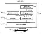
- FIG. 5 An exemplary embodiment of a device 500 according to an embodiment of the present invention is schematically illustrated in Figure 5 .
- the devices 501, 502 of the description above may be implemented according to the architecture of device 500.
- the device 500 is capable of being operatively connected to at least one domain 100 (corresponding for instance to one of the aforementioned domains A and B), via an appropriate physical interface 540.
- the device 500 comprises a probe signal generator 560 configured to generate an appropriate probe signal for transmission over the domain 100 via the physical layer interface 540. Prior to transmission, the probe signal is cyclically shifted by the cyclic shifter 550 , if necessary.
- probe signal generator must not be interpreted to imply that the probe signal is generated on-the-fly in the device 500 ; the generator may retrieve a standardized probe signal from a memory, and present this to the cyclic shifter 550 for further processing. Alternatively, the generator may retrieve a pre-shifted probe signal from a memory, and present this for transmission to the physical layer interface 540.
- the feedback signal corresponding to the probe signal is received at the physical interfaces 540 and relayed to the signal filtering agent 530.
- the signal filtering agent 530 may be operatively connected to the probe signal generation 560 to receive information about the transmitted probe signal from the latter for interference cancellation purposes. Furthermore, the signal filtering agent 530 uses the special mathematical properties of the combined feedback signal to separate the relevant reflection of the device's own probe signal.
- the signal filtering agent 530 is operatively connected to the cyclic shifter 550 or otherwise capable of obtaining information about the cyclic shift that was applied to the transmitted probe signal, in order to remove the shift from the received version of the signal.
- the device 500 further comprises logic, designated as probe signal processor 520 , configured to analyze the received feedback in order to assess the properties of the physical medium.
- a physical layer configuration agent 510 preferably uses the results of this assessment to determine the most appropriate physical layer transmission parameters, and to configure the physical layer interface accordingly.
- processors may be provided through the use of dedicated hardware as well as hardware capable of executing software in association with appropriate software.
- the functions may be provided by a single dedicated processor, by a single shared processor, or by a plurality of individual processors, some of which may be shared.
- processor or “controller” should not be construed to refer exclusively to hardware capable of executing software, and may implicitly include, without limitation, digital signal processor (DSP) hardware, network processor, application specific integrated circuit (ASIC), field programmable gate array (FPGA), read only memory (ROM) for storing software, random access memory (RAM), and non volatile storage.
- DSP digital signal processor
- ASIC application specific integrated circuit
- FPGA field programmable gate array
- ROM read only memory
- RAM random access memory
- non volatile storage Other hardware, conventional and/or custom, may also be included.
- any switches shown in the figures are conceptual only. Their function may be carried out through the operation of program logic, through dedicated logic, through the interaction of program control and dedicated logic, or even manually, the particular technique being selectable by the implementer as more specifically understood from the context.
- a first step 610 represents processing carried out by the devices 501, 502 attached to the respective domains 101, 102.
- Device A 1 501 prepares its probe signal P A in sub-step 611
- device B 1 502 prepares its probe signal P B in sub-step 612.
- These sub-steps 611, 612 are appropriately coordinated to ensure that the resulting probe signals P A and P B are subjected to a relative cyclic shift (this implies that only at least one of the signals P A and P B needs to undergo an actual shift).
- This coordination is schematically represented by the dashed double arrow between the boxes representing sub-steps 611 and 612.
- a second step 620 represents the processing at the IDB 400, which implies interaction between the domain managers DM-A and DM-B associated with the respective domains A and B on the one hand, and the LLC X-I interface controller, which is responsible for coordinating the transmissions on said domains, on the other hand.
- the LLC X-I interface controller maintains a partner list for this purpose, which in the example used above includes a partnership between A 1 and B 1 .
- a third step 630 again represents processing carried out by the devices 501, 502 attached to the respective domains 101, 102.
- Device A 1 501 receives the combined retransmitted probe signal in sub-step 631
- device B 1 502 receives the combined retransmitted probe signal in sub-step 632. No further coordination between the sub-steps 631, 632 is necessary at this point, provided that both devices are aware of the relative cyclic shift that was applied in the first step 610. Further processing of the received combined retransmitted probe signal is then applied as explained in connection with Figure 5 .
- each device 501, 502 has access to the feedback signal corresponding to the probe signal it transmitted. This access is represented by the dashed arrows from the TX processing sub-steps 611 and 612 to the RX processing sub-steps 631 and 632, respectively.
- program storage devices e.g., digital data storage media, which are machine or computer readable and encode machine executable or computer-executable programs of instructions, wherein said instructions perform some or all of the steps of said above-described methods.
- the program storage devices may be, e.g., digital memories, magnetic storage media such as a magnetic disks and magnetic tapes, hard drives, or optically readable digital data storage media.
- the embodiments are also intended to cover computers programmed to perform said steps of the above-described methods.
Description
- The present invention pertains to the field of home networks, more in particular to the field of data transmission over diverse physical home network segments.
- In home networks, in particular home networks according to the G.hn family of Recommendations developed by the ITU-T (see ITU-T Rec. G.9961), communication between domains is conducted via domain managers. This architecture has limited scalability and does not allow for true bidirectional interaction across domains. Additionally, known channel probing schemes for such networks tend to be inefficient.
- The article "G.hn: The New ITU-T Home Networking Standard" by Vladimir Oksman and Stefano Galli (IEEE Communications Magazine, October 2009, p. 138-145) gives an overview of G.hn technology focusing on the main principles used to build a single transmission scheme for multiple types of wires.
-
WO-A-2010/087173 , entitled "Wireless transmitter and reference signal transmission method" discloses a wireless transmitter and a reference signal transmission method that are stated to improve channel estimation accuracy. In a terminal, which transmits a reference signal using n (n is anon-negative integer 2 or greater) band blocks (which correspond to clusters here), which are disposed with spaces therebetween in a frequency direction, a reference signal controller (106) switches the reference signal formation method of a reference signal generator between a first formation method and a second formation method based on the number (n) of band blocks. In addition, a threshold value setting unit adjusts a switching threshold value based on the frequency spacing between band blocks. - Accordingly, it is an object of embodiments of the present invention to provide a more efficient channel probing scheme for multi-domain networks.
- According to an aspect of the present invention, there is provided a method for assessing the quality of a communication channel in a multi-domain network, the method comprising at a device attached to said communication channel: transmitting a probe signal onto said communication channel in a first time slot, said transmitting being coordinated with the transmission of at least one alien probe signal by another network node in said first time slot; subsequently to said transmitting, receiving a mixed feedback signal, said mixed feedback signal comprising a first component corresponding to said probe signal and a second component corresponding to said at least one alien probe signal; extracting said first component from said mixed feedback signal; and assessing the quality of said communication channel on the basis of said extracted first component; wherein said probe signal and said at least one alien probe signal have a substantially identical temporal and spectral extent, except for a relative cyclic shift in the time domain , so as to facilitate their separation after having been superimposed.
- According to an aspect of the present invention, there is provided a method to be applied in assessing the quality of a plurality of communication channels in a multi-domain network, the method comprising at a bridge attached to said plurality of communication channels: receiving a plurality of coordinated probe signals from said respective communication channels in a first time slot; superimposing said plurality of coordinated probe signals to form a mixed feedback signal; and subsequently to said receiving, transmitting said mixed feedback signal onto said plurality of communication channels; wherein said coordinated signals have a substantially identical temporal and spectral extent, except for a relative cyclic shift in the time domain, so as to facilitate their separation after having been superimposed.
- According to an aspect of the present invention, there is provided a computer program configured to cause a processor to carry out the method as described above.
- According to an aspect of the present invention, there is provided an apparatus for assessing the quality of a communication channel in a multi-domain network, the apparatus being adapted to produce a probe signal, the apparatus comprising: a physical layer interface, adapted to transmit said probe signal onto said channel, and to subsequently receive a mixed feedback signal from said channel; a filtering agent, operatively connected to said physical layer interface, said filtering agent being configured to extract a component corresponding to said probe signal from said mixed feedback signal; and a probe signal processor, operatively connected to said filtering agent, said probe signal processor being configured to assess the quality of said communication channel on the basis of said extracted component; and a cyclic shifter configured to apply a cyclic shift to said probe signal prior to transmission by said physical layer interface, said cyclic shift being different from a cyclic shift applied by said peer apparatus, so as to facilitate its separation after having been superimposed onto a probe signal from a peer apparatus.
- According to an aspect of the present invention, there is provided an apparatus for bridging a plurality of communication channels in a multi-domain network, the apparatus comprising: a plurality of physical layer interfaces, adapted to transmit and receive signals over respective ones of said plurality of communication channels; and a signal combination agent, operatively connected to said plurality of physical layer interfaces, said signal combination agent being configured to generate, upon receiving probe signals from said physical layer interfaces, a mixed feedback signal representing a superposition of said probe signals; wherein said apparatus is configured to transmit said mixed feedback signal onto said plurality of communication channels; and wherein said probe signals have a substantially identical temporal and spectral extent, except for a relative cyclic shift in the time domain, so as to facilitate their separation after having been superimposed.
- Some embodiments of apparatus and/or methods in accordance with embodiments of the present invention are now described, by way of example only, and with reference to the accompanying drawings, in which:
-
Figure 1 illustrates channel usage during the channel assessment stage according to a known method; -
Figure 2 schematically illustrates an exemplary network architecture in which embodiments of the present invention may be deployed; -
Figure 3 illustrates channel usage during the channel assessment stage according to an embodiment of the present invention; -
Figure 4 schematically illustrates an apparatus according to an embodiment of the present invention; -
Figure 5 schematically illustrates an apparatus according to another embodiment of the present invention; and -
Figure 6 schematically illustrates the interaction between elements of an embodiment of the present embodiment. - International Telecommunication Union (ITU) G.hn standard was defined to enable the broadband data communication required by in-house high data rate (i.e., broadband) applications. In G.hn, different domains are available for the in-house network access over different mediums (e.g., the copper twisted-pairs, coax, power line cables). However, the available network resources (e.g., frequency spectrum) are limited by the characteristics of the medium and structure of the network. In general, the G.hn medium(s) can be seen as a broadcast channel(s), where devices share the same medium and available network resources.
- To improve spectrum efficiency (i.e., throughput, latency, etc.) a bi-directional mechanism, where both the transmitter and the receiver communicate as a part of the same transmission session, between two nodes may be used for sessions that are bi-directional in nature. One example is transmission control protocol (TCP) session. The bi-directional mechanism in G.hn is available only to nodes communicating directly within the same domain with two service flows:
- (i) the forward flow from the originating node to the endpoint node (assigned by the originating node); and
- (ii) the reverse flow from the endpoint node to the originating node (assigned by the endpoint node).
- However, for inter-domain bi-directional communication in G.hn the channel assessment is required for coherent detection. This is a challenging task since multiple devices access the same network resources at the same time based on time division multiple access (TDMA) scheme.
- The channel assessment probe frame is specified in current version of ITU-T G.9960 Recommendation. The payload of the probe frame shall contain a number of symbol frames with no data. The number of the symbol frames (and OFDM symbols) shall be indicated in the PHY-frame header via the PRBSYM field and can be of
size 4, 8, 12, ..., 64 OFDM payload symbols in the probe frame. The probe frames (i.e., signals) are sent/received based on TDMA scheme either directly between two devices (where one device acts as a domain master) or via a relay. - Unlike direct (relay-less) and relay-assisted sessions in G.hn home networks, where signals from different users are separated in time to avoid interference, in bidirectional inter-domain G.hn communication, the device's probe signals interfere in the same time slot. Bi-directional inter-domain G.hn communication is described in European patent application no.
11305586.7 - Hence, in the case of probe transmission, a domain master cannot estimate the CSIs of different home network devices.
- Although the invention is described in the context of G.hn networks, the skilled person will understand that this is done for illustrative purposes only, and that the invention is not limited to G.hn networks. Any reference to G.hn or G.hn related terminology should be understood as applying equally to similar multi-domain network architectures. This includes home networks, i.e. networks for residential use.
-
Figure 1 diagrammatically illustrates a straightforward method to avoid this problem in G.hn networks, which consists of allocating different 5 time slots, essentially performing probe signaling in a time-division multiple access (TDMA) fashion. - As shown in
Figure 1 , the information about the channel must be fed back to the device after each probe transmission. This will reduce the network throughput since the G.hn home network may have a large number of operating devices. Thus, the channel assessment for inter-domain communication in G.hn may be important and limiting factor for different home network services where the content is kept within the network and/or distributed over different domains. - It is an object of the present invention to provide a more efficient channel assessment for inter-domain bi-directional transmission in G.hn home networks. The invention is inter alia based on the insight of the inventor that the throughput, and thus the efficiency, can be improved by reducing the required number of signaling intervals within the probe frames and the domain master. The invention is further based on the insight of the inventor that this reduction can be achieved by judiciously combining the transmission of several signals in a manner that allows reconstruction of the original signals.
- G.hn supports multi-port device functionality that can be exploited to enable efficient inter-domain bi-directional transmission. In this example we consider inter-domain bi-directional communication between two devices A1 and B1 from different domains A and B, respectively.
-
Figure 2 provides a schematic representation of the proposed architecture of a network, preferably a home network, more preferably a G.hn network, comprising twodomains 101, 102 (corresponding for instance to the aforementioned domains A and B), where twopartner devices 501, 502 (corresponding for instance to the aforementioned devices A1 and B1) ask for the network resources to send their corresponding probe signals. - The LLC function of the Inter-domain
bridge 400 triggers a new logical interface (henceforth X-I interface) to initiate the inter-domain mechanism between the targeted pair ofdevices devices - With reference to
Figure 3 , the two stages of the channel probing scheme according to the present invention will now be described in more detail. - In the first time slot, identified as "
Stage 1" inFigure 3 , both devices A1 and B1 (501, 502) send their respective probe signals PA and PB, to the corresponding multi-port DMs (seeFig. 2 ), which are interconnected over the LLC function with designatedIDB node 400. - The probe signals PA and PB from both devices are designed in such way so as to avoid interference during
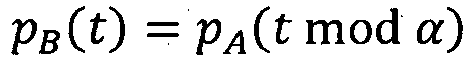
Stage 1. In that way, both devices A1 and B1 (501, 502) can access the network resources at the same time. This constraint is met by cyclically shifting one of the probe signals (e.g., PB of B1) in the time domain. Consequently, the frequency spectrum of the probe signal PB will be shifted in the frequency domain with respect to the frequency spectrum of the probe signal PA of device A1. Accordingly, the frequency domain envelopes of the probe signals as received through the respective channels will not overlap, which in turn allows the receivers to extract the corresponding channel transfer function in the frequency domain without interference from the partner device's probe signal. - For illustrative purposes only, the above concept can be further explained by the following mathematical derivation.
- Without loss of generality, we consider a first probe signal PA, associated with domain A, and a second probe signal pB, associated with domain B, where pB is in fact a cyclically delayed version of the same probe signal, such that, in the time domain, the following expression holds true:
- Turning to a frequency domain representation, and using HA and HB to denote the channel matrices of domains A and B, respectively, the combined probe signal as received at the
inter-domain bridge 400 can be expressed as follows:
- Mathematically, the situation is therefore equivalent to receiving the single probe signal PA through a combined channel with the following associated channel matrix:


- In the second time slot, identified as "
Stage 2" inFigure 3 , the probe signals as received on different ports ofIDB node 400 are superimposed. Next, theIDB 400 causes the combined probe signals to be broadcast by A-DM and B-DM in their respective domains. - If more than two devices are used in the scheme according to the present invention, the cyclic shift parameters should be designed to avoid spectrum overlapping in the frequency domain for every pair of probe signals, while keeping in mind that the shift should be larger than the guard interval. Consequently, by using the cyclic shift parameters and partner list, the
IDB 400 is able to initiate and coordinate channel assessment for inter-domain bi-directional communication between two devices from different domains. - An
exemplary IDB node 400 according to an embodiment of the present invention is schematically illustrated inFigure 4 . Thenode 400 is capable of being operatively connected to at least twodomains 101, 102 (corresponding for instance to the aforementioned domains A and B), via appropriatephysical interfaces physical interfaces signal combination agent 420. The received probe signals are cyclically shifted relative to each other as described above. Additionally, a small amount of non-cyclic relative delay may be due to different propagation delays in therespective domains - The combined probe signal as generated by the
signal combination agent 420 is made available to the transmission logic of thenode 400, preferably to theX-I interface controller 410, which causes the combined probe signal to be broadcast on thetarget domains - The channel assessment at the receiver ends 501, 502 is rather simple. For the purpose of this description and without loss of generality, the receiver ends 501, 502 are assumed to correspond to the aforementioned devices A1 and B1. Since both A1 and B1 know their own respective probe signals, they are each preferably configured to subtract any interference caused by that their own respective signal, which may be present as "echo" at the destination. The corresponding channel information is subsequently estimated in the frequency domain between A1 and the partner device B1 by first dividing the received signal with the transmitted probe signal to obtain an estimate of the "combined" channel transfer function, and then decomposing this "combined" channel transfer function into the contributions of the
respective domains - An exemplary embodiment of a
device 500 according to an embodiment of the present invention is schematically illustrated inFigure 5 . Thedevices device 500. Thedevice 500 is capable of being operatively connected to at least one domain 100 (corresponding for instance to one of the aforementioned domains A and B), via an appropriatephysical interface 540. Thedevice 500 comprises aprobe signal generator 560 configured to generate an appropriate probe signal for transmission over thedomain 100 via thephysical layer interface 540. Prior to transmission, the probe signal is cyclically shifted by thecyclic shifter 550, if necessary. The term "probe signal generator" must not be interpreted to imply that the probe signal is generated on-the-fly in thedevice 500; the generator may retrieve a standardized probe signal from a memory, and present this to thecyclic shifter 550 for further processing. Alternatively, the generator may retrieve a pre-shifted probe signal from a memory, and present this for transmission to thephysical layer interface 540. - The feedback signal corresponding to the probe signal, consisting of a reflected superposition of the original probe signal and that of one or more other devices, is received at the
physical interfaces 540 and relayed to thesignal filtering agent 530. Thesignal filtering agent 530 may be operatively connected to theprobe signal generation 560 to receive information about the transmitted probe signal from the latter for interference cancellation purposes. Furthermore, thesignal filtering agent 530 uses the special mathematical properties of the combined feedback signal to separate the relevant reflection of the device's own probe signal. Thesignal filtering agent 530 is operatively connected to thecyclic shifter 550 or otherwise capable of obtaining information about the cyclic shift that was applied to the transmitted probe signal, in order to remove the shift from the received version of the signal. - The
device 500 further comprises logic, designated asprobe signal processor 520, configured to analyze the received feedback in order to assess the properties of the physical medium. A physicallayer configuration agent 510 preferably uses the results of this assessment to determine the most appropriate physical layer transmission parameters, and to configure the physical layer interface accordingly. - The functions of the various elements shown in the figures, including any functional blocks labeled as "processors", "controllers", or "agents", may be provided through the use of dedicated hardware as well as hardware capable of executing software in association with appropriate software. When provided by a processor, the functions may be provided by a single dedicated processor, by a single shared processor, or by a plurality of individual processors, some of which may be shared. Moreover, explicit use of the term "processor" or "controller" should not be construed to refer exclusively to hardware capable of executing software, and may implicitly include, without limitation, digital signal processor (DSP) hardware, network processor, application specific integrated circuit (ASIC), field programmable gate array (FPGA), read only memory (ROM) for storing software, random access memory (RAM), and non volatile storage. Other hardware, conventional and/or custom, may also be included. Similarly, any switches shown in the figures are conceptual only. Their function may be carried out through the operation of program logic, through dedicated logic, through the interaction of program control and dedicated logic, or even manually, the particular technique being selectable by the implementer as more specifically understood from the context.
- The proposed method procedure flow is illustrated by the flow diagram of
Figure 6 . - A
first step 610 represents processing carried out by thedevices respective domains Device A 1 501 prepares its probe signal PA insub-step 611, anddevice B 1 502 prepares its probe signal PB insub-step 612. Thesesub-steps boxes representing sub-steps - A
second step 620 represents the processing at theIDB 400, which implies interaction between the domain managers DM-A and DM-B associated with the respective domains A and B on the one hand, and the LLC X-I interface controller, which is responsible for coordinating the transmissions on said domains, on the other hand. The LLC X-I interface controller maintains a partner list for this purpose, which in the example used above includes a partnership between A1 and B1. - A
third step 630 again represents processing carried out by thedevices respective domains Device A 1 501 receives the combined retransmitted probe signal in sub-step 631, anddevice B 1 502 receives the combined retransmitted probe signal insub-step 632. No further coordination between the sub-steps 631, 632 is necessary at this point, provided that both devices are aware of the relative cyclic shift that was applied in thefirst step 610. Further processing of the received combined retransmitted probe signal is then applied as explained in connection withFigure 5 . - The result of applying the method according to the described embodiment of the invention is that each
device TX processing sub-steps RX processing sub-steps 631 and 632, respectively. - A person of skill in the art would readily recognize that steps of various above described methods can be performed by programmed computers. Herein, some embodiments are also intended to cover program storage devices, e.g., digital data storage media, which are machine or computer readable and encode machine executable or computer-executable programs of instructions, wherein said instructions perform some or all of the steps of said above-described methods. The program storage devices may be, e.g., digital memories, magnetic storage media such as a magnetic disks and magnetic tapes, hard drives, or optically readable digital data storage media. The embodiments are also intended to cover computers programmed to perform said steps of the above-described methods.
Claims (5)
- A method for assessing the quality of a communication channel in a home network where communication between domains is conducted via domain managers, the method comprising at a device (501) attached to said communication channel (101):- transmitting a probe signal onto said communication channel (101) in a first time slot, said transmitting being coordinated with the transmission in said first time slot of at least one alien probe signal by another network node (502);- subsequently to said transmitting, receiving a mixed feedback signal, said mixed feedback signal comprising a first component corresponding to said probe signal and a second component corresponding to said at least one alien probe signal;- extracting said first component from said mixed feedback signal;- assessing the quality of said communication channel (101) on the basis of said extracted first component;wherein said probe signal and said at least one alien probe signal have a substantially identical temporal and spectral extent, except for a relative cyclic shift in the time domain, so as to facilitate their separation after having been superimposed.
- A method to be applied in assessing the quality of a plurality of communication channels (101, 102) in a home network where communication between domains is conducted via domain managers, the method comprising at a bridge (400) attached to said plurality of communication channels (101, 102):- receiving a plurality of coordinated probe signals from said respective communication channels (101, 102) in a first time slot;- superimposing said plurality of coordinated probe signals to form a mixed feedback signal;- subsequently to said receiving, transmitting said mixed feedback signal onto said plurality of communication channels (101, 102);wherein said coordinated probe signals have a substantially identical temporal and spectral extent, except for a relative cyclic shift in the time domain so as to facilitate their separation after having been superimposed.
- A computer program configured to cause a processor to carry out the method of any of the preceding claims.
- An apparatus (500) for assessing the quality of a communication channel in a home network where communication between domains is conducted via domain managers, the apparatus being adapted to produce a probe signal, the apparatus comprising:- a physical layer interface (540), adapted to transmit said probe signal onto said channel (100) in a first time slot, said transmitting being coordinated with the transmission in said first time slot of at least one alien probe signal by another network node (502), and to subsequently receive a mixed feedback signal from said channel (100), said mixed feedback signal comprising a first component corresponding to said probe signal and a second component corresponding to said at least one alien probe signal;- a filtering agent (530), operatively connected to said physical layer interface (540), said filtering agent (530) being configured to extract a component corresponding to said probe signal from said mixed feedback signal;- a probe signal processor (520), operatively connected to said filtering agent (530), said probe signal processor (520) being configured to assess the quality of said communication channel (100) on the basis of said extracted component; anda cyclic shifter (550) configured to apply a cyclic shift to said probe signal prior to transmission by said physical layer interface (540), said cyclic shift being different from a cyclic shift applied by said peer apparatus, so as to facilitate its separation after having been superimposed onto a probe signal from a peer apparatus.
- An apparatus (400) for bridging a plurality of communication channels (101, 102) in a home network where communication between domains is conducted via domain managers, the apparatus (400) comprising- a plurality of physical layer interfaces (441, 442), adapted to transmit and receive signals over respective ones of said plurality of communication channels (101, 102);- a signal combination agent (420), operatively connected to said plurality of physical layer interfaces (441, 442), said signal combination agent (420) being configured to generate, upon receiving in a first time slot probe signals from said physical layer interfaces (441, 442), a mixed feedback signal representing a superposition of said probe signals;wherein said apparatus (400) is configured to subsequently transmit said mixed feedback signal onto said plurality of communication channels (101, 102); and
wherein said probe signals have a substantially identical temporal and spectral extent, except for a relative cyclic shift in the time domain so as to facilitate their separation after having been superimposed.
Priority Applications (4)
| Application Number | Priority Date | Filing Date | Title |
|---|---|---|---|
| EP20110306176 EP2571199B1 (en) | 2011-09-19 | 2011-09-19 | Method and apparatus for assessing the quality of a communication channel in a multi-domain network |
| PCT/EP2012/066593 WO2013041327A1 (en) | 2011-09-19 | 2012-08-27 | Method and apparatus for assessing the quality of a communication channel in a multi-domain network |
| US14/239,815 US9462494B2 (en) | 2011-09-19 | 2012-08-27 | Method and apparatus for assessing the quality of a communication channel in a multi-domain network |
| CN201280045353.2A CN103814548B (en) | 2011-09-19 | 2012-08-27 | For assessing the method and apparatus of the quality of communication channel in multiple-domain network |
Applications Claiming Priority (1)
| Application Number | Priority Date | Filing Date | Title |
|---|---|---|---|
| EP20110306176 EP2571199B1 (en) | 2011-09-19 | 2011-09-19 | Method and apparatus for assessing the quality of a communication channel in a multi-domain network |
Publications (2)
| Publication Number | Publication Date |
|---|---|
| EP2571199A1 EP2571199A1 (en) | 2013-03-20 |
| EP2571199B1 true EP2571199B1 (en) | 2015-04-29 |
Family
ID=46785399
Family Applications (1)
| Application Number | Title | Priority Date | Filing Date |
|---|---|---|---|
| EP20110306176 Active EP2571199B1 (en) | 2011-09-19 | 2011-09-19 | Method and apparatus for assessing the quality of a communication channel in a multi-domain network |
Country Status (4)
| Country | Link |
|---|---|
| US (1) | US9462494B2 (en) |
| EP (1) | EP2571199B1 (en) |
| CN (1) | CN103814548B (en) |
| WO (1) | WO2013041327A1 (en) |
Families Citing this family (1)
| Publication number | Priority date | Publication date | Assignee | Title |
|---|---|---|---|---|
| EP2773144A1 (en) * | 2013-03-01 | 2014-09-03 | Thomson Licensing | Method of diagnosis of degradation in a heterogeneous network using a neighbour network |
Family Cites Families (7)
| Publication number | Priority date | Publication date | Assignee | Title |
|---|---|---|---|---|
| GB0004439D0 (en) | 2000-02-25 | 2000-04-12 | Central Research Lab Ltd | Radio communication detector apparatus and method |
| EP2016683A4 (en) * | 2006-04-27 | 2014-07-16 | Texas Instruments Inc | Methods and apparatus to allocate reference signals in wireless communication systems |
| US8203983B2 (en) * | 2007-03-15 | 2012-06-19 | Lantiq Deutschland Gmbh | Multi-domain network with centralized management |
| BRPI1007424B1 (en) * | 2009-01-29 | 2021-02-23 | Sun Patent Trust | TRANSMISSION AND RECEPTION DEVICES CONFIGURED FOR REFERENCE TRANSMITTING, TRANSMISSION AND RECEPTION METHODS, AND INTEGRATED CIRCUIT |
| KR101645490B1 (en) * | 2009-05-07 | 2016-08-05 | 엘지전자 주식회사 | A method for tranmsimittng signal using a frame of a predetermined cyclic prefix length in a wireless communication system |
| US20110082939A1 (en) * | 2009-10-02 | 2011-04-07 | Michael Peter Montemurro | Methods and apparatus to proxy discovery and negotiations between network entities to establish peer-to-peer communications |
| EP2525533B1 (en) | 2011-05-16 | 2014-02-26 | Alcatel Lucent | Method and apparatus for providing bidirectional communication between segments of a home network |
-
2011
- 2011-09-19 EP EP20110306176 patent/EP2571199B1/en active Active
-
2012
- 2012-08-27 US US14/239,815 patent/US9462494B2/en active Active
- 2012-08-27 CN CN201280045353.2A patent/CN103814548B/en active Active
- 2012-08-27 WO PCT/EP2012/066593 patent/WO2013041327A1/en active Application Filing
Also Published As
| Publication number | Publication date |
|---|---|
| CN103814548B (en) | 2016-11-16 |
| US20140204792A1 (en) | 2014-07-24 |
| WO2013041327A1 (en) | 2013-03-28 |
| CN103814548A (en) | 2014-05-21 |
| EP2571199A1 (en) | 2013-03-20 |
| US9462494B2 (en) | 2016-10-04 |
Similar Documents
| Publication | Publication Date | Title |
|---|---|---|
| US10856243B2 (en) | System, method, and apparatus for end-to-end synchronization, adaptive link resource reservation and data tunneling | |
| JP2006129470A (en) | Dynamic frequency domain (fd) coexistence method for power line communication system | |
| KR20110104524A (en) | Receiver determined probe | |
| KR102396938B1 (en) | Wireless networks and devices | |
| EP3098982A1 (en) | Optical burst transport network, node, transmission method and computer storage medium | |
| US9450643B2 (en) | Method and apparatus for relaying messages in a PLC network | |
| CN108293233A (en) | uplink pilot reference signal | |
| Da Silva | Cable and wireless networks: Theory and practice | |
| EP3076603B1 (en) | Interference mitigation apparatus and interference mitigation method for home network transmission line, and communication system using same | |
| JP3389492B2 (en) | Simultaneous transmission device and simultaneous transmission method | |
| EP2571199B1 (en) | Method and apparatus for assessing the quality of a communication channel in a multi-domain network | |
| US20140204952A1 (en) | Method and apparatus for exchanging data signals over a plurality of domains in a home network | |
| HUE027242T2 (en) | Method and arrangement in a wireless communication system | |
| US9749118B2 (en) | Method and apparatus for providing bidirectional communication between segments of a home network | |
| Vandendorpe et al. | Rate-optimized power allocation for OFDM transmission with multiple DF/regenerative relays and an improved protocol | |
| CN106374974A (en) | Method and device for adaptively adjusting power line carrier communication frame length | |
| Tang | Traffic Modeling of a Finite-Source Power Line Communication Network | |
| JP2008017423A (en) | Method of conducting uninterrupted transmission, uninterrupted communications equipment, receiver and computer program | |
| Babu et al. | High performance OFDM based multi relay multi pair communication networks | |
| Shensheng | Traffic Modeling of a Finite-Source Power Line Communication Network |
Legal Events
| Date | Code | Title | Description |
|---|---|---|---|
| PUAI | Public reference made under article 153(3) epc to a published international application that has entered the european phase |
Free format text: ORIGINAL CODE: 0009012 |
|
| AK | Designated contracting states |
Kind code of ref document: A1 Designated state(s): AL AT BE BG CH CY CZ DE DK EE ES FI FR GB GR HR HU IE IS IT LI LT LU LV MC MK MT NL NO PL PT RO RS SE SI SK SM TR |
|
| AX | Request for extension of the european patent |
Extension state: BA ME |
|
| 111Z | Information provided on other rights and legal means of execution |
Free format text: AL AT BE BG CH CY CZ DE DK EE ES FI FR GB GR HR HU IE IS IT LI LT LU LV MC MK MT NL NO PL PT RO RS SE SI SK SM TR Effective date: 20130410 |
|
| 17P | Request for examination filed |
Effective date: 20130920 |
|
| RBV | Designated contracting states (corrected) |
Designated state(s): AL AT BE BG CH CY CZ DE DK EE ES FI FR GB GR HR HU IE IS IT LI LT LU LV MC MK MT NL NO PL PT RO RS SE SI SK SM TR |
|
| 17Q | First examination report despatched |
Effective date: 20131212 |
|
| RAP1 | Party data changed (applicant data changed or rights of an application transferred) |
Owner name: ALCATEL LUCENT |
|
| REG | Reference to a national code |
Ref country code: DE Ref legal event code: R079 Ref document number: 602011016065 Country of ref document: DE Free format text: PREVIOUS MAIN CLASS: H04L0012280000 Ipc: H04L0012260000 |
|
| D11X | Information provided on other rights and legal means of execution (deleted) | ||
| GRAP | Despatch of communication of intention to grant a patent |
Free format text: ORIGINAL CODE: EPIDOSNIGR1 |
|
| RIC1 | Information provided on ipc code assigned before grant |
Ipc: H04W 24/06 20090101ALI20141118BHEP Ipc: H04L 25/02 20060101ALI20141118BHEP Ipc: H04L 27/26 20060101ALI20141118BHEP Ipc: H04L 12/26 20060101AFI20141118BHEP |
|
| INTG | Intention to grant announced |
Effective date: 20141202 |
|
| GRAS | Grant fee paid |
Free format text: ORIGINAL CODE: EPIDOSNIGR3 |
|
| GRAA | (expected) grant |
Free format text: ORIGINAL CODE: 0009210 |
|
| AK | Designated contracting states |
Kind code of ref document: B1 Designated state(s): AL AT BE BG CH CY CZ DE DK EE ES FI FR GB GR HR HU IE IS IT LI LT LU LV MC MK MT NL NO PL PT RO RS SE SI SK SM TR |
|
| REG | Reference to a national code |
Ref country code: GB Ref legal event code: FG4D |
|
| REG | Reference to a national code |
Ref country code: CH Ref legal event code: EP |
|
| REG | Reference to a national code |
Ref country code: AT Ref legal event code: REF Ref document number: 724957 Country of ref document: AT Kind code of ref document: T Effective date: 20150515 |
|
| REG | Reference to a national code |
Ref country code: IE Ref legal event code: FG4D |
|
| REG | Reference to a national code |
Ref country code: DE Ref legal event code: R096 Ref document number: 602011016065 Country of ref document: DE Effective date: 20150611 |
|
| REG | Reference to a national code |
Ref country code: NL Ref legal event code: VDEP Effective date: 20150429 |
|
| REG | Reference to a national code |
Ref country code: AT Ref legal event code: MK05 Ref document number: 724957 Country of ref document: AT Kind code of ref document: T Effective date: 20150429 |
|
| REG | Reference to a national code |
Ref country code: FR Ref legal event code: PLFP Year of fee payment: 5 |
|
| REG | Reference to a national code |
Ref country code: LT Ref legal event code: MG4D |
|
| PG25 | Lapsed in a contracting state [announced via postgrant information from national office to epo] |
Ref country code: NL Free format text: LAPSE BECAUSE OF FAILURE TO SUBMIT A TRANSLATION OF THE DESCRIPTION OR TO PAY THE FEE WITHIN THE PRESCRIBED TIME-LIMIT Effective date: 20150429 |
|
| PG25 | Lapsed in a contracting state [announced via postgrant information from national office to epo] |
Ref country code: LT Free format text: LAPSE BECAUSE OF FAILURE TO SUBMIT A TRANSLATION OF THE DESCRIPTION OR TO PAY THE FEE WITHIN THE PRESCRIBED TIME-LIMIT Effective date: 20150429 Ref country code: FI Free format text: LAPSE BECAUSE OF FAILURE TO SUBMIT A TRANSLATION OF THE DESCRIPTION OR TO PAY THE FEE WITHIN THE PRESCRIBED TIME-LIMIT Effective date: 20150429 Ref country code: HR Free format text: LAPSE BECAUSE OF FAILURE TO SUBMIT A TRANSLATION OF THE DESCRIPTION OR TO PAY THE FEE WITHIN THE PRESCRIBED TIME-LIMIT Effective date: 20150429 Ref country code: NO Free format text: LAPSE BECAUSE OF FAILURE TO SUBMIT A TRANSLATION OF THE DESCRIPTION OR TO PAY THE FEE WITHIN THE PRESCRIBED TIME-LIMIT Effective date: 20150729 Ref country code: ES Free format text: LAPSE BECAUSE OF FAILURE TO SUBMIT A TRANSLATION OF THE DESCRIPTION OR TO PAY THE FEE WITHIN THE PRESCRIBED TIME-LIMIT Effective date: 20150429 Ref country code: PT Free format text: LAPSE BECAUSE OF FAILURE TO SUBMIT A TRANSLATION OF THE DESCRIPTION OR TO PAY THE FEE WITHIN THE PRESCRIBED TIME-LIMIT Effective date: 20150831 |
|
| PG25 | Lapsed in a contracting state [announced via postgrant information from national office to epo] |
Ref country code: IS Free format text: LAPSE BECAUSE OF FAILURE TO SUBMIT A TRANSLATION OF THE DESCRIPTION OR TO PAY THE FEE WITHIN THE PRESCRIBED TIME-LIMIT Effective date: 20150829 Ref country code: LV Free format text: LAPSE BECAUSE OF FAILURE TO SUBMIT A TRANSLATION OF THE DESCRIPTION OR TO PAY THE FEE WITHIN THE PRESCRIBED TIME-LIMIT Effective date: 20150429 Ref country code: RS Free format text: LAPSE BECAUSE OF FAILURE TO SUBMIT A TRANSLATION OF THE DESCRIPTION OR TO PAY THE FEE WITHIN THE PRESCRIBED TIME-LIMIT Effective date: 20150429 Ref country code: GR Free format text: LAPSE BECAUSE OF FAILURE TO SUBMIT A TRANSLATION OF THE DESCRIPTION OR TO PAY THE FEE WITHIN THE PRESCRIBED TIME-LIMIT Effective date: 20150730 Ref country code: AT Free format text: LAPSE BECAUSE OF FAILURE TO SUBMIT A TRANSLATION OF THE DESCRIPTION OR TO PAY THE FEE WITHIN THE PRESCRIBED TIME-LIMIT Effective date: 20150429 |
|
| PG25 | Lapsed in a contracting state [announced via postgrant information from national office to epo] |
Ref country code: DK Free format text: LAPSE BECAUSE OF FAILURE TO SUBMIT A TRANSLATION OF THE DESCRIPTION OR TO PAY THE FEE WITHIN THE PRESCRIBED TIME-LIMIT Effective date: 20150429 Ref country code: EE Free format text: LAPSE BECAUSE OF FAILURE TO SUBMIT A TRANSLATION OF THE DESCRIPTION OR TO PAY THE FEE WITHIN THE PRESCRIBED TIME-LIMIT Effective date: 20150429 |
|
| REG | Reference to a national code |
Ref country code: DE Ref legal event code: R097 Ref document number: 602011016065 Country of ref document: DE |
|
| PG25 | Lapsed in a contracting state [announced via postgrant information from national office to epo] |
Ref country code: CZ Free format text: LAPSE BECAUSE OF FAILURE TO SUBMIT A TRANSLATION OF THE DESCRIPTION OR TO PAY THE FEE WITHIN THE PRESCRIBED TIME-LIMIT Effective date: 20150429 Ref country code: RO Free format text: LAPSE BECAUSE OF NON-PAYMENT OF DUE FEES Effective date: 20150429 Ref country code: SK Free format text: LAPSE BECAUSE OF FAILURE TO SUBMIT A TRANSLATION OF THE DESCRIPTION OR TO PAY THE FEE WITHIN THE PRESCRIBED TIME-LIMIT Effective date: 20150429 Ref country code: PL Free format text: LAPSE BECAUSE OF FAILURE TO SUBMIT A TRANSLATION OF THE DESCRIPTION OR TO PAY THE FEE WITHIN THE PRESCRIBED TIME-LIMIT Effective date: 20150429 |
|
| PLBE | No opposition filed within time limit |
Free format text: ORIGINAL CODE: 0009261 |
|
| STAA | Information on the status of an ep patent application or granted ep patent |
Free format text: STATUS: NO OPPOSITION FILED WITHIN TIME LIMIT |
|
| 26N | No opposition filed |
Effective date: 20160201 |
|
| PG25 | Lapsed in a contracting state [announced via postgrant information from national office to epo] |
Ref country code: LU Free format text: LAPSE BECAUSE OF FAILURE TO SUBMIT A TRANSLATION OF THE DESCRIPTION OR TO PAY THE FEE WITHIN THE PRESCRIBED TIME-LIMIT Effective date: 20150919 Ref country code: IT Free format text: LAPSE BECAUSE OF FAILURE TO SUBMIT A TRANSLATION OF THE DESCRIPTION OR TO PAY THE FEE WITHIN THE PRESCRIBED TIME-LIMIT Effective date: 20150429 Ref country code: MC Free format text: LAPSE BECAUSE OF FAILURE TO SUBMIT A TRANSLATION OF THE DESCRIPTION OR TO PAY THE FEE WITHIN THE PRESCRIBED TIME-LIMIT Effective date: 20150429 |
|
| REG | Reference to a national code |
Ref country code: CH Ref legal event code: PL |
|
| PG25 | Lapsed in a contracting state [announced via postgrant information from national office to epo] |
Ref country code: SI Free format text: LAPSE BECAUSE OF FAILURE TO SUBMIT A TRANSLATION OF THE DESCRIPTION OR TO PAY THE FEE WITHIN THE PRESCRIBED TIME-LIMIT Effective date: 20150429 |
|
| REG | Reference to a national code |
Ref country code: IE Ref legal event code: MM4A |
|
| PG25 | Lapsed in a contracting state [announced via postgrant information from national office to epo] |
Ref country code: CH Free format text: LAPSE BECAUSE OF NON-PAYMENT OF DUE FEES Effective date: 20150930 Ref country code: IE Free format text: LAPSE BECAUSE OF NON-PAYMENT OF DUE FEES Effective date: 20150919 Ref country code: LI Free format text: LAPSE BECAUSE OF NON-PAYMENT OF DUE FEES Effective date: 20150930 |
|
| PG25 | Lapsed in a contracting state [announced via postgrant information from national office to epo] |
Ref country code: BE Free format text: LAPSE BECAUSE OF FAILURE TO SUBMIT A TRANSLATION OF THE DESCRIPTION OR TO PAY THE FEE WITHIN THE PRESCRIBED TIME-LIMIT Effective date: 20150429 |
|
| REG | Reference to a national code |
Ref country code: FR Ref legal event code: PLFP Year of fee payment: 6 |
|
| PG25 | Lapsed in a contracting state [announced via postgrant information from national office to epo] |
Ref country code: MT Free format text: LAPSE BECAUSE OF FAILURE TO SUBMIT A TRANSLATION OF THE DESCRIPTION OR TO PAY THE FEE WITHIN THE PRESCRIBED TIME-LIMIT Effective date: 20150429 |
|
| PG25 | Lapsed in a contracting state [announced via postgrant information from national office to epo] |
Ref country code: SM Free format text: LAPSE BECAUSE OF FAILURE TO SUBMIT A TRANSLATION OF THE DESCRIPTION OR TO PAY THE FEE WITHIN THE PRESCRIBED TIME-LIMIT Effective date: 20150429 Ref country code: HU Free format text: LAPSE BECAUSE OF FAILURE TO SUBMIT A TRANSLATION OF THE DESCRIPTION OR TO PAY THE FEE WITHIN THE PRESCRIBED TIME-LIMIT; INVALID AB INITIO Effective date: 20110919 Ref country code: BG Free format text: LAPSE BECAUSE OF FAILURE TO SUBMIT A TRANSLATION OF THE DESCRIPTION OR TO PAY THE FEE WITHIN THE PRESCRIBED TIME-LIMIT Effective date: 20150429 |
|
| PG25 | Lapsed in a contracting state [announced via postgrant information from national office to epo] |
Ref country code: CY Free format text: LAPSE BECAUSE OF FAILURE TO SUBMIT A TRANSLATION OF THE DESCRIPTION OR TO PAY THE FEE WITHIN THE PRESCRIBED TIME-LIMIT Effective date: 20150429 Ref country code: SE Free format text: LAPSE BECAUSE OF FAILURE TO SUBMIT A TRANSLATION OF THE DESCRIPTION OR TO PAY THE FEE WITHIN THE PRESCRIBED TIME-LIMIT Effective date: 20150429 |
|
| PG25 | Lapsed in a contracting state [announced via postgrant information from national office to epo] |
Ref country code: TR Free format text: LAPSE BECAUSE OF FAILURE TO SUBMIT A TRANSLATION OF THE DESCRIPTION OR TO PAY THE FEE WITHIN THE PRESCRIBED TIME-LIMIT Effective date: 20150429 |
|
| REG | Reference to a national code |
Ref country code: FR Ref legal event code: PLFP Year of fee payment: 7 |
|
| PG25 | Lapsed in a contracting state [announced via postgrant information from national office to epo] |
Ref country code: MK Free format text: LAPSE BECAUSE OF FAILURE TO SUBMIT A TRANSLATION OF THE DESCRIPTION OR TO PAY THE FEE WITHIN THE PRESCRIBED TIME-LIMIT Effective date: 20150429 |
|
| REG | Reference to a national code |
Ref country code: FR Ref legal event code: PLFP Year of fee payment: 8 |
|
| PG25 | Lapsed in a contracting state [announced via postgrant information from national office to epo] |
Ref country code: AL Free format text: LAPSE BECAUSE OF FAILURE TO SUBMIT A TRANSLATION OF THE DESCRIPTION OR TO PAY THE FEE WITHIN THE PRESCRIBED TIME-LIMIT Effective date: 20150429 |
|
| PGFP | Annual fee paid to national office [announced via postgrant information from national office to epo] |
Ref country code: FR Payment date: 20190815 Year of fee payment: 9 |
|
| PG25 | Lapsed in a contracting state [announced via postgrant information from national office to epo] |
Ref country code: FR Free format text: LAPSE BECAUSE OF NON-PAYMENT OF DUE FEES Effective date: 20200930 |
|
| REG | Reference to a national code |
Ref country code: DE Ref legal event code: R079 Ref document number: 602011016065 Country of ref document: DE Free format text: PREVIOUS MAIN CLASS: H04L0012260000 Ipc: H04L0043000000 |
|
| PGFP | Annual fee paid to national office [announced via postgrant information from national office to epo] |
Ref country code: GB Payment date: 20230803 Year of fee payment: 13 |
|
| PGFP | Annual fee paid to national office [announced via postgrant information from national office to epo] |
Ref country code: DE Payment date: 20230802 Year of fee payment: 13 |