EP2571107A2 - Connector and electronic device having the same - Google Patents
Connector and electronic device having the same Download PDFInfo
- Publication number
- EP2571107A2 EP2571107A2 EP12250143A EP12250143A EP2571107A2 EP 2571107 A2 EP2571107 A2 EP 2571107A2 EP 12250143 A EP12250143 A EP 12250143A EP 12250143 A EP12250143 A EP 12250143A EP 2571107 A2 EP2571107 A2 EP 2571107A2
- Authority
- EP
- European Patent Office
- Prior art keywords
- case
- portions
- hole
- annular joint
- abutting
- Prior art date
- Legal status (The legal status is an assumption and is not a legal conclusion. Google has not performed a legal analysis and makes no representation as to the accuracy of the status listed.)
- Withdrawn
Links
- 239000011347 resin Substances 0.000 claims abstract description 41
- 229920005989 resin Polymers 0.000 claims abstract description 41
- 229920006122 polyamide resin Polymers 0.000 claims description 19
- 239000002184 metal Substances 0.000 description 17
- 229910052751 metal Inorganic materials 0.000 description 17
- 238000005304 joining Methods 0.000 description 15
- XLYOFNOQVPJJNP-UHFFFAOYSA-N water Substances O XLYOFNOQVPJJNP-UHFFFAOYSA-N 0.000 description 15
- 239000000428 dust Substances 0.000 description 12
- 238000000465 moulding Methods 0.000 description 9
- 239000000463 material Substances 0.000 description 7
- 230000002349 favourable effect Effects 0.000 description 6
- 230000013011 mating Effects 0.000 description 6
- 238000005520 cutting process Methods 0.000 description 5
- 238000005452 bending Methods 0.000 description 4
- 150000002739 metals Chemical class 0.000 description 3
- 239000000470 constituent Substances 0.000 description 2
- 238000000151 deposition Methods 0.000 description 2
- 238000001746 injection moulding Methods 0.000 description 2
- 238000000034 method Methods 0.000 description 2
- 230000004048 modification Effects 0.000 description 2
- 238000012986 modification Methods 0.000 description 2
- XUIMIQQOPSSXEZ-UHFFFAOYSA-N Silicon Chemical compound [Si] XUIMIQQOPSSXEZ-UHFFFAOYSA-N 0.000 description 1
- 230000006978 adaptation Effects 0.000 description 1
- 239000000853 adhesive Substances 0.000 description 1
- 230000001070 adhesive effect Effects 0.000 description 1
- 230000000694 effects Effects 0.000 description 1
- 238000003780 insertion Methods 0.000 description 1
- 238000004519 manufacturing process Methods 0.000 description 1
- 229910052710 silicon Inorganic materials 0.000 description 1
- 239000010703 silicon Substances 0.000 description 1
- 239000000758 substrate Substances 0.000 description 1
Images








Classifications
-
- H—ELECTRICITY
- H01—ELECTRIC ELEMENTS
- H01R—ELECTRICALLY-CONDUCTIVE CONNECTIONS; STRUCTURAL ASSOCIATIONS OF A PLURALITY OF MUTUALLY-INSULATED ELECTRICAL CONNECTING ELEMENTS; COUPLING DEVICES; CURRENT COLLECTORS
- H01R13/00—Details of coupling devices of the kinds covered by groups H01R12/70 or H01R24/00 - H01R33/00
- H01R13/46—Bases; Cases
- H01R13/52—Dustproof, splashproof, drip-proof, waterproof, or flameproof cases
-
- H—ELECTRICITY
- H01—ELECTRIC ELEMENTS
- H01R—ELECTRICALLY-CONDUCTIVE CONNECTIONS; STRUCTURAL ASSOCIATIONS OF A PLURALITY OF MUTUALLY-INSULATED ELECTRICAL CONNECTING ELEMENTS; COUPLING DEVICES; CURRENT COLLECTORS
- H01R13/00—Details of coupling devices of the kinds covered by groups H01R12/70 or H01R24/00 - H01R33/00
- H01R13/46—Bases; Cases
- H01R13/52—Dustproof, splashproof, drip-proof, waterproof, or flameproof cases
- H01R13/5202—Sealing means between parts of housing or between housing part and a wall, e.g. sealing rings
-
- H—ELECTRICITY
- H01—ELECTRIC ELEMENTS
- H01R—ELECTRICALLY-CONDUCTIVE CONNECTIONS; STRUCTURAL ASSOCIATIONS OF A PLURALITY OF MUTUALLY-INSULATED ELECTRICAL CONNECTING ELEMENTS; COUPLING DEVICES; CURRENT COLLECTORS
- H01R13/00—Details of coupling devices of the kinds covered by groups H01R12/70 or H01R24/00 - H01R33/00
- H01R13/46—Bases; Cases
- H01R13/502—Bases; Cases composed of different pieces
- H01R13/506—Bases; Cases composed of different pieces assembled by snap action of the parts
-
- H—ELECTRICITY
- H01—ELECTRIC ELEMENTS
- H01R—ELECTRICALLY-CONDUCTIVE CONNECTIONS; STRUCTURAL ASSOCIATIONS OF A PLURALITY OF MUTUALLY-INSULATED ELECTRICAL CONNECTING ELEMENTS; COUPLING DEVICES; CURRENT COLLECTORS
- H01R13/00—Details of coupling devices of the kinds covered by groups H01R12/70 or H01R24/00 - H01R33/00
- H01R13/46—Bases; Cases
- H01R13/52—Dustproof, splashproof, drip-proof, waterproof, or flameproof cases
- H01R13/5216—Dustproof, splashproof, drip-proof, waterproof, or flameproof cases characterised by the sealing material, e.g. gels or resins
-
- H—ELECTRICITY
- H01—ELECTRIC ELEMENTS
- H01R—ELECTRICALLY-CONDUCTIVE CONNECTIONS; STRUCTURAL ASSOCIATIONS OF A PLURALITY OF MUTUALLY-INSULATED ELECTRICAL CONNECTING ELEMENTS; COUPLING DEVICES; CURRENT COLLECTORS
- H01R13/00—Details of coupling devices of the kinds covered by groups H01R12/70 or H01R24/00 - H01R33/00
- H01R13/648—Protective earth or shield arrangements on coupling devices, e.g. anti-static shielding
- H01R13/658—High frequency shielding arrangements, e.g. against EMI [Electro-Magnetic Interference] or EMP [Electro-Magnetic Pulse]
-
- H—ELECTRICITY
- H01—ELECTRIC ELEMENTS
- H01R—ELECTRICALLY-CONDUCTIVE CONNECTIONS; STRUCTURAL ASSOCIATIONS OF A PLURALITY OF MUTUALLY-INSULATED ELECTRICAL CONNECTING ELEMENTS; COUPLING DEVICES; CURRENT COLLECTORS
- H01R13/00—Details of coupling devices of the kinds covered by groups H01R12/70 or H01R24/00 - H01R33/00
- H01R13/648—Protective earth or shield arrangements on coupling devices, e.g. anti-static shielding
- H01R13/658—High frequency shielding arrangements, e.g. against EMI [Electro-Magnetic Interference] or EMP [Electro-Magnetic Pulse]
- H01R13/6581—Shield structure
-
- H—ELECTRICITY
- H04—ELECTRIC COMMUNICATION TECHNIQUE
- H04B—TRANSMISSION
- H04B1/00—Details of transmission systems, not covered by a single one of groups H04B3/00 - H04B13/00; Details of transmission systems not characterised by the medium used for transmission
- H04B1/38—Transceivers, i.e. devices in which transmitter and receiver form a structural unit and in which at least one part is used for functions of transmitting and receiving
- H04B1/40—Circuits
-
- H—ELECTRICITY
- H01—ELECTRIC ELEMENTS
- H01R—ELECTRICALLY-CONDUCTIVE CONNECTIONS; STRUCTURAL ASSOCIATIONS OF A PLURALITY OF MUTUALLY-INSULATED ELECTRICAL CONNECTING ELEMENTS; COUPLING DEVICES; CURRENT COLLECTORS
- H01R12/00—Structural associations of a plurality of mutually-insulated electrical connecting elements, specially adapted for printed circuits, e.g. printed circuit boards [PCB], flat or ribbon cables, or like generally planar structures, e.g. terminal strips, terminal blocks; Coupling devices specially adapted for printed circuits, flat or ribbon cables, or like generally planar structures; Terminals specially adapted for contact with, or insertion into, printed circuits, flat or ribbon cables, or like generally planar structures
- H01R12/70—Coupling devices
- H01R12/71—Coupling devices for rigid printing circuits or like structures
- H01R12/72—Coupling devices for rigid printing circuits or like structures coupling with the edge of the rigid printed circuits or like structures
- H01R12/722—Coupling devices for rigid printing circuits or like structures coupling with the edge of the rigid printed circuits or like structures coupling devices mounted on the edge of the printed circuits
- H01R12/724—Coupling devices for rigid printing circuits or like structures coupling with the edge of the rigid printed circuits or like structures coupling devices mounted on the edge of the printed circuits containing contact members forming a right angle
Definitions
- the invention relates to connectors and electronic devices having the same.
- JP-A Japanese Patent Application Laid-Open (JP-A) No. 2001-250629 discloses a connector installed in a portable terminal such as a smartphone.
- the connector has a cap of a silicon resin fittingly attached thereto. The cap reduces water intrusion through the connector into the portable terminal.
- a problem with the above conventional connector is that improper attachment of the cap to the connector tends to cause water intrusion through the connector into the portable terminal.
- the invention has been contrived in view of the above circumstances.
- the invention provides a waterproof connector and an electronic device having the same.
- a connector of the invention includes a case, a body, a contact, and an annular joint.
- the case includes a through hole and a periphery of the through hole.
- the body includes a main body, the main body including a front portion received in the through hole of the case and a rear portion continuous or integrally formed with the front portion.
- the contact includes an intermediate portion held in the main body, a contact portion received in the through hole of the case, and a tail portion located on an opposite side of the intermediate portion from the contact portion.
- the annular joint is made of an insulating resin and joins the rear portion of the main body and the periphery of the through hole of the case.
- the connector can reduce intrusion of water and dust through between the body and the case.
- the connector With the annular joint of an insulating resin fabricated by outsert molding or a similar method, the connector can provide favorable waterproofness and dustproofness at low cost.
- the body may further include an abutting portion being provided on the rear portion of the main body and abutting the periphery of the through hole of the case.
- the abutting portion may be embedded in the annular joint. According to this aspect of the invention, the annular joint embedded with the abutting portion provides an improved joining strength in joining the rear portion of the main body and the periphery of the through hole of the case.
- the connector may further include a shield case of tuboid shape possessing electrical conductivity.
- the shield case may fit in the through hole of the case.
- the front portion of the main body may fit in the shield case.
- the contact portion of the contact may be enclosed by the shield case.
- the annular joint may join the rear portion of the main body, the periphery of the through hole of the case, and the shield case.
- the connector can reduce water intrusion through between the body and the shield case and through between the case and the shield case. Further, with the contact portion of the contact enclosed by the shield case, the connector provides improved electromagnetic interference (EMI) characteristics.
- EMI electromagnetic interference
- the shield case may include a tuboid portion fitting in the through hole of the case, and an engaging portion continuous with the tuboid portion.
- the engaging portion may be engaged with the periphery of the through hole of the case and embedded in the annular joint.
- This aspect of the invention makes it easy to position the shield case with respect to the case in the assembly of the connector, by engaging the engaging portion of the shield case with the periphery of the through hole of the case. Further, as the engaging portion is embedded in the annular joint, the annular joint provides an improved joining strength in joining the shield case, the rear portion of the main body, and the periphery of the through hole of the case.
- the engaging portion may be folded back toward the tuboid portion side.
- the engaging portion may include an end abutting the periphery of the through hole of the case.
- This aspect of the invention makes it easy to position the shield case with respect to the case, simply by bringing the end of the engaging portion into abutment with the periphery of the through hole of the case.
- the shield case may include a tuboid portion fitting in the through hole of the case, and a connecting portion being continuous with the tuboid portion and passing through the annular joint.
- the connecting portion passes through the annular joint, i.e. it is partially embedded in the annular joint. Therefore, the annular joint provides a further improved joining strength in joining the shield case, the rear portion of the main body, and the periphery of the through hole of the case.
- the connecting portion may include a curved portion curved in a generally U-shape or in a serpentine shape and embedded in the annular joint.
- the curved portion of a generally U- or serpentine shape is embedded in the annular joint, it is possible to increase the surface distance (contact area) of the curved portion with respect to the resin of the annular joint. Even when a narrow gap exists along the boundary of the curved portion and the resin of the annular joint, the gap should be lengthened in accordance with the increase of the surface distance. Therefore, the connector can reduce intrusion of water and dust through the gap if any. Consequently, the connector provides favorably improved waterproofness and dustproofness.
- the connecting portion may further include a basal portion continuous or integrally formed with the tuboid portion and embedded in the annular joint, and a distal portion projecting from the annular joint.
- the curved portion may bridge the basal portion and the distal portion.
- the curved portion of a generally U- or serpentine shape bridges between the basal portion and the distal portion.
- the gap should have a curved part of generally U- or serpentine shape along the curved portion. That is, the gap formed along the basal portion and the curved portion should not be formed straight. Such non-straight gap is unlikely to allow intrusion of water and dust. Consequently, the connector can be further improved in terms of waterproofness and dustproofness.
- the curved portion may include first and second opposed portions facing each other, and a protrusion provided on at least one of the first and second opposed portions.
- the protrusion may abut the other of the first and second opposed portions and create a space between the first and second opposed portions.
- the resin of the annular joint may be filled in the space.
- the abutment of the protrusion against the other of the first and second opposed portions creates a space between the first and second opposed portions.
- the resin of the annular joint is filled in the space, it is possible to further increase the surface distance (contact area) of the curved portion with respect to the annular joint. Consequently, the connector can be further improved in terms of waterproofness and dustproofness.
- the shield case may include a tuboid portion fitting in the through hole of the case, and a fixing portion continuous or integrally formed with the tuboid portion and embedded in the annular joint.
- the annular joint provides an improved joining strength in joining the shield case, the rear portion of the main body, and the periphery of the through hole of the case.
- the connector may be provided with a plurality of abutting portions circumferentially arranged at intervals on and around an outer circumferential surface of the main body.
- the annular joint has embedded therein the plurality of abutting portions circumferentially arranged at intervals on and around the outer circumferential surface of the main body. Therefore, the annular joint provides an improved joining strength in joining the shield case, the rear portion of the main body, and the periphery of the through hole of the case.
- the connector may be provided with a plurality of abutting portions circumferentially arranged at intervals on and around an outer circumferential surface of the main body, and the fixing portion may fit in between adjacent ones of the abutting portions.
- the annular joint has embedded therein the plurality of abutting portions circumferentially arranged at intervals on and around the outer circumferential surface of the main body. Therefore, the annular joint provides an improved joining strength in joining the shield case, the rear portion of the main body, and the periphery of the through hole of the case. Further, the shield case can be easily attached to the body in the assembly of the connector by fitting the fixing portion of the shield case between the adjacent abutting portions.
- One of the periphery of the through hole of the case and the abutting portion may be provided with a protrusion, and the other thereof may be provided with a recess to fit over the protrusion.
- This aspect of the invention makes it easy to attach the body to the case in the assembly of the connector by fitting the protrusion in the recess.
- the intermediate portion of the contact may be preferably embedded in the main body. This aspect of the invention improves the waterproofness and the dustproofness of the connector.
- the connector may further include a shield cover possessing electrical conductivity to partially cover the case and the annular joint. This aspect of the invention further improves the EMI characteristic of the connector.
- the connector may preferably be configured such that at least one of the case, the body, and the annular joint is made of a polyamide resin.
- polyamide resins generally provide favorable adherence to other kinds of resin materials and metals
- the connector of this aspect of the invention can provide improved waterproofness and dustproofness.
- the connector of this aspect can also provide an improved prying resistance.
- the connector may include a ring-shaped gasket fitting around the case.
- the ring-shaped gasket fitting around the case can be interposed between the connector and a housing of an electronic device for mounting the connector.
- the gasket can therefore reduce intrusion of water, dust, and grit through between the connector and the housing of the electronic device.
- An electronic device of the invention may include the connector according to any one of the above aspects.
- Embodiments 1 to 3 of the invention will be described below.
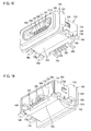
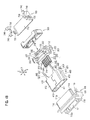
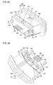
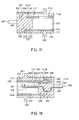
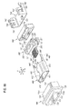
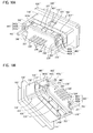
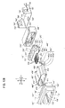
- the connector includes a case 100, a body 200, a plurality of contacts 300, a shield case 400, an annular joint 500, a gasket 600, and a shield cover 700.
- the respective components of the connector will be described in detail below.
- the widthwise, fore-aft, top-bottom directions of the connector is indicated as X, Y, and Z, respectively, in Figs. 4A and 4B .
- the Y direction is perpendicular to the X direction
- the Z direction is perpendicular to the X and Y directions.
- the case 100 is a tube of an insulating resin such as a polyamide resin.
- the case 100 includes a tuboid case body 110 of tuboid shape, and a square annular frame 120 surrounding the case body 110.
- the case body 110 is provided with a through hole 111 passing through the case body 110 in the Y direction.
- a periphery 112a of the through hole 111 is provided on the front side (one side in the Y direction) of the case body 110, and a periphery 112b of the through hole 111 is provided on the rear side (the other side in the Y direction) of the case body 110.
- the rear side periphery 112b corresponds to the periphery of the through hole of the case as defined in the claims.
- the gasket 600 fits around the case body 110.
- the gasket 600 can be interposed between the case body 110 and a housing (not shown) of an electronic device for mounting the connector.
- the gasket 600 interposed between the case body 110 and the housing can reduce intrusion of water, dust, or the like through between them into the electronic device.
- a pair of rectangular locking recesses 113 is provided in opposite end faces in the X direction of the case body 110. Opposite ends in the X direction of the lower end of the case body 110 is formed with a pair of locking grooves 114 extending in the Y direction. In the inner space of the case body 110, the ceiling is provided with a pair of grooves 115 extending in the Y direction and a pair of recesses 116 as shown in Figs. 3B and 3C . The recesses 116 communicate with the grooves 115 and are open out to the rear side of the case body 110.
- the shield case 400 as shown in Figs. 4A and 4B is formed of an electrically conductive metal plate.
- the shield case 400 includes a tuboid portion 410, a pair of engaging portions 420, and a fixing portion 430, and a pair of connecting portions 440.
- the outer shape of the tuboid portion 410 conforms to the inner shape of the through hole 111 of the case body 110.
- the tuboid portion 410 accordingly fits in the through hole 111 of the case body 110.
- the tuboid portion 410 includes a top plate 411, a bottom plate 412, and a pair of side plates 413.
- the top plate 411 is provided with a pair of lugs 411 a, and a pair of abutting-stops 411b as shown in Figs. 3B and 3C .
- the lugs 411a are formed by cutting portions of the top plate 411 and raising them upward (one side in the Z direction).
- the lugs 411a are received in the grooves 115 of the case body 110.
- the abutting-stops 411 b are provided behind the lugs 411a of the top plate 411 and project downward (in the other side in the Z direction).
- the engaging portions 420 of generally U-shape are jointed to the rear ends of the side plates 413 of the tuboid portion 410 and folded back outward and forward.
- the engaging portions 420 have ends 421.
- the ends 421 are in abutment and engagement with the periphery 112b of the case body 110.
- the fixing portion 430 is a rectangular plate integrally formed or continuous with the rear end of the top plate 411 of the tuboid portion 410 and extends in the Y direction.
- the connecting portions 440 are arms continuous with the rear end of the bottom plate 412 of the tuboid portion 410 and extend in the Y direction.
- the connecting portions 440 each have a basal portion 441 and a distal portion 442.
- the connecting portions 440 are curved such that the lower surfaces of the distal portions 442 are at the same height position as the lower surfaces of tail portions 320 (to be described) of the contacts 300.
- the body 200 is made of an insulating resin such as a polyamide resin.
- the body 200 includes a main body 210, a pair of abutting portions 221, a pair of abutting portions 222, an abutting portion 223, a rear plate 230, and a tongue 240.
- the main body 210 is a block of an outer shape conforming to the inner shape of the tuboid portion 410 of the shield case 400.
- the main body 210 has a front portion 211 and a rear portion 212 integrally formed or continuous with the front portion 211.
- the front portion 211 fits in the tuboid portion 410.
- a pair of recesses 211 a is formed at the top of the front face of the front portion 211.
- the abutting-stops 411b of the shield case 400 are received in the recesess 211 a and abut the back faces of the recesses 211 a. This abutment reduces over-insertion of the main body 210 into the tuboid portion 410.
- the plate-shaped tongue 240 projects from the front portion 211. As shown in Fig. 3A , the tongue 240 is located in the tuboid portion 410. The lower face of the tongue 240 is formed with a plurality of accommodating grooves 241 extending in the Y direction.
- the pair of abutting portions 221, the pair of abutting portions 222, and the abutting portion 223 are circumferentially arranged at intervals.
- the abutting portions 221, the abutting portions 222, and the abutting portion 223 abut the periphery 112b of the case 100 and the rear face of the tuboid portion 410 of the shield case 400.
- the abutting portions 221 are each provided with a protrusion 221 a. As shown in Figs. 3B and 3C , the protrusions 221 a fit in the pair of recesses 116 of the case body 110.
- a space S1 is provided between the pair of abutting portions 221.
- a space S2 is provided between each of the pair of abutting portions 221 and each of the pair of abutting portions 222.
- a space S3 is provided between each of the pair of abutting portions 222 and the abutting portion 223.
- the fixing portion 430 of the shield case 400 is received in the space S1 and fits between the abutting portions 221.
- the engaging portions 420 are received in the spaces S2.
- the connecting portions 440 pass through the spaces S3, so that the basal portions 441 of the connecting portions 440 are located in the spaces S3.
- the rear plate 230 is integrally formed or continuous with the rear portion 212 of the main body 210. As shown in Figs.
- the contacts 300 are formed of electrically conductive metal plates. As shown in Fig. 3D , the contacts 300 each include a contact portion 310, a tail portion 320, and an intermediate portion 330.
- the intermediate portions 330 are generally L-shaped plates securely embedded in the main body 210 and the rear plate 230 of the body 200. The other ends in the Y direction (rear ends) of the intermediate portions 330 project downward from the rear plate 230 to be disposed in the cutaway 231.
- the contact portions 310 are plates that are each continuous or integrally formed with one end in the Y direction (front end) of each of the intermediate portions 330 and extend in the Y direction to be received in the accommodating grooves 241 of the tongue 240.
- the contact portions 310 are disposed in and enclosed by the tuboid portion 410 of the shield case 400, so that the connector provides improved electromagnetic interference (EMI) characteristics.
- the tail portions 320 are plates that are each continuous or integrally formed with the other end in the Y direction (rear end) of each of the intermediate portions 330.
- the tail portions 320 are each bent substantially perpendicularly to the other end of each of the intermediate portions 330 and extend in the Y direction.
- the tail portions 320 are located on the opposite side of the intermediate portions 330 from the contact portions 310 in the Y direction (i.e. the intermediate portions 330 are located between the contact portions 310 and the tail portions 320 in the Y direction).
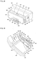
- the annular joint 500 is an annular body of an insulating resin such as a polyamide resin as shown in Figs. 2A, 2B , 4A , and 4B .
- the annular joint 500 joins the periphery 112b of the case 100, the rear surface of the tuboid portion 410 of the shield case 400, and the outer circumferential surface of the rear portion 212 of the main body 210 of the body 200.
- the annular joint 500 covers the rear portion 212 of the body 200.
- the annular joint 500 has embedded therein the pair of abutting portions 221, the pair of abutting portions 222, the abutting portion 223, the rear plate 230, the engaging portions 420, the fixing portion 430, and the basal portions 441 of the connecting portions 440.
- the resin of the annular joint 500 is filled in the spaces S1 to S3 and the gap between the rear plate 230 and the abutting portions 221 and 222 in such a manner as to cover the pair of abutting portions 221, the pair of abutting portions 222, the abutting portion 223, the rear plate 230, the engaging portions 420, the fixing portion 430, and the basal portions 441 of the connecting portions 440.
- the annular joint 500 has an inner shape with projections and recesses conforming to the shapes of the pair of abutting portions 221, the pair of abutting portions 222, and the abutting portion 223 (the abutting portions 221, 222, 223 are disposed on the rear portion 212 of the main body 210), the rear plate 230, the pair of engaging portions 420, the fixing portion 430, the basal portions 441 of the pair of connecting portions 440, the spaces S1 to S3, and the gap between the rear plate 230 and the abutting portions 221 and 222.
- the shield cover 700 is an electrically conductive metal plate formed into a generally downward U-shape as shown in Figs. 4A and 4B .
- the shield cover 700 includes a cover body 710 of generally U-shape, a pair of first locking pieces 720, a pair of second locking pieces 730, and four connecting pieces 740.
- the cover body 710 has a top plate and a pair of side plates. The side plates are continuous with ends in the X direction of the top plate and bent perpendicularly to the top plate.
- the cover body 710 is placed on the rear portion of the case body 110 of the case 100 and on the annular joint 500. The cover body 710 in this state covers the intermediate portions 330 of the contacts 300.
- the first locking pieces 720 are formed by cutting and bending inward portions of the side plates of the cover body 710. The first locking pieces 720 are locked in the locking recess 113 of the case body 110.
- the second locking pieces 730 are continuous with the centers at the lower ends of the side plates of the cover body 710 and are bent inward to extend perpendicularly to the side plates.
- the second locking pieces 730 are locked in the locking grooves 114 of the case body 110.
- Each pair of the four connecting pieces 740 is continuous with the lower end of each of the side plates of the cover body 710 and bent outward to extend perpendicularly to the side plate.
- the lower surfaces of the connecting pieces 740 are located at the same height position as the lower surfaces of the tail portions 320 of the contacts 300.
- the connector configured as described above may be manufactured in the following steps.
- the first step is to press-form the contacts 300 out of a metal plate. Thereafter, the contacts 300 are put into a die (not shown), into which an insulating resin is poured for performing insert molding.
- the insulating resin is molded into the body 200, in which the intermediate portions 330 of the contacts 300 are securely embedded in the main body 210 and the rear plate 230.
- the contact portions 310 are received in the respective accommodating grooves 241 of the tongue 240 of the body 200.
- the tail portions 320 are arranged behind the lower end of the rear plate 230 of the body 200.
- the next step is to press-form the shield case 400 out of a metal plate.
- the tongue 240 of the body 200 Into the tuboid portion 410 of the shield case 400 are inserted the tongue 240 of the body 200 and the front portion 211 of the main body 210. Accordingly, the front portion 211 of the body 200 fits in the tuboid portion 410 of the shield case 400, and the tongue 240 and the contact portions 310 of the contacts 300 are located inside the tuboid portion 410. Also, the abutting portions 221, 222, and 223 of the body 200 abut the rear face of the tuboid portion 410 of the shield case 400.
- the abutting-stops 411b of the shield case 400 are inserted into the recesses 211a of the body 200 and abut the back surfaces of the recesses 211 a.
- the fixing portion 430 of the shield case 400 fits between the pair of abutting portions 221.
- the pair of engaging portions 420 of the shield case 400 are inserted into the spaces S2 between the pair of abutting portions 221 and the pair of abutting portions 222.
- the connecting portions 440 of the shield case 400 pass through the spaces S3 between the pair of abutting portions 222 and the abutting portion 223 such that the basal portions 441 of the connecting portions 440 are located in the spaces S3.
- the next step is to prepare the case 100 by injection molding, i.e. by pouring an insulating resin into a die not shown.
- the gasket 600 is fittingly placed around the case body 110 of the case 100.
- the tuboid portion 410 of the shield case 400 is then fittingly placed into the through hole 111 of the case 100.
- the abutting portions 221, 222, and 223 of the body 200 abut the periphery 112b of the case 100
- the engaging portions 420 of the shield case 400 also abut the periphery 112b of the case 100.
- the protrusions 221a of the body 200 fit in the recesses 116 of the case 100.
- the tongue 240 of the body 200, the contact portions 310 of the contacts 300, and the front portion 211 of the main body 210 are located inside the through hole 111 of the case 100.
- the case 100, the body 200, the contacts 300, and the shield case 400 are combined as described above, they are put into a die (not shown), and an insulating resin is poured into space around the outer circumferential surface of the rear portion 212 of the main body 210, i.e. the outsert molding process is performed.
- the molded insulating resin forms the annular joint 500, which exists around the outer circumferential surface of the rear portion 212 of the main body 210.
- the annular joint 500 serves to join the outer circumferential surface of the rear portion 212 of the main body 210 to the periphery 112b of the case 100 and the rear face of the tuboid portion 410 of the shield case 400.
- the annular joint 500 has embedded therein (accommodates) the pair of abutting portions 221, the pair of abutting portions 222, the abutting portion 223, the rear plate 230, the pair of engaging portions 420, the fixing portion 430, and the basal portions 441 of the pair of connecting portions 440.
- the next step is to press-form the shield cover 700 out of a metal plate.
- the pair of second locking pieces 730 of the shield cover 700 is then inserted into the pair of locking grooves 114 of the case 100.
- the first locking pieces 720 of the shield cover 700 are thus locked in the locking recesses 113 of the case 100.
- the cover body 710 of the shield cover 700 is thus placed on the rear portion of the case body 110 and the annular joint 500.
- the connector may be thus assembled and mounted onto a circuit board of an electronic device in the following steps. First, the connector is placed onto the circuit board. At this time, the tail portions 320 of the contacts 300 are brought into contact with associated signal electrodes on the circuit board. The connecting portions 440 of the shield case 400 are brought into contact with associated ground electrodes on the circuit board. The connecting pieces 740 of the shield cover 700 are brought into contact with associated ground electrodes on the circuit board. Thereafter, the tail portions 320 of the contacts 300 are soldered to the associated signal electrodes of the circuit board. The connecting portions 440 of the shield case 400 are soldered to the associated ground electrodes of the circuit board. The connecting pieces 740 of the shield cover 700 are soldered to the associated ground electrodes of the substrate.
- the connector may be connected to a mating plug connector in the following manner.
- the plug is inserted into the tuboid portion 410 of the connector.
- contacts of the plug are brought into contact with the associated contact portions 310 of the contacts 300 of the connector.
- the connector is thus electrically connected to the mating plug.
- the annular joint 500 joins the rear portion 212 of the main body 210 to the periphery 112b of the through hole 111 of the case 100 and the rear face of the tuboid portion 410 of the shield case 400. Therefore, the connector can reduce intrusion of water and dust through between the body 200 and the case 100, through between the body 200 and the tuboid portion 410 of the shield case 400, and through between the case 100 and the tuboid portion 410 of the shield case 400. Also, the annular joint 500 is formed around the rear portion 212 of the main body 210 by outsert molding. Therefore, the connector can provide favorable waterproofness and dustproofness at low cost.
- the annular joint 500 has embedded therein (accommodates) the pair of abutting portions 221, the pair of abutting portions 222, the abutting portion 223, the rear plate 230, the pair of engaging portions 420, the fixing portion 430, and the basal portions 441 of the pair of connecting portions 440.
- the annular joint 500 thus provides improved joining strength of the rear portion 212 of the main body 210 with respect to the tuboid portion 410 of the shield case 400 and the periphery 112b of the case 100.
- the tuboid portion 410 of the shield case 400 fits in the through hole 111 of the case 100
- the abutting portions 221, 222, and 223 of the body 200 abut the periphery 112b of the case 100
- the engaging portions 420 of the shield case 400 abut the periphery 112b of the case 100
- the protrusions 221a of the body 200 fit in the recesses 116 of the case 100. It is therefore easy to position the body 200 and the shield case 400 with respect to the case 100.
- At least one of the case 100, the body 200, and the annular joint 500 may be made of a polyamide resin.
- Polyamide resins generally provide favorable adherence to other kinds of resin materials and metals.
- the connector including polyamide resin components can provide improved waterproofness and dustproofness. Further, polyamide resins generally provide favorably high rigidity than other resin materials. Therefore, the connector including polyamide resin components can provide an improved prying resistance.
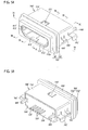
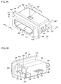
- the connector shown in Figs. 5A to 6B is different from the connector of Embodiment 1 in that this connector is of a mid-mount type, i.e. the connector is connected to a circuit board as fitting in a recess or hole of the circuit board. More specifically, the connector has the same configuration as the connector of Embodiment 1 except that a case 100', a body 200', contacts 300', a shield case 400', an annular joint 500', and a shield cover 700' are of different shape from the corresponding components of the connector of Embodiment 1 for adaptation to the mid-mount type.
- Embodiment 1 Only the differences will be described in detail below, and the configurations common to Embodiment 1 will not be described.
- the case, the body, the contacts, the shield case, the annular joint, and the shield cover of this connector and their subcomponents will be referred to with reference numerals added with a symbol _'_ for the sake of distinction from the case, the body, the contacts, the shield case, the annular joint, and the shield cover of Embodiment 1.
- the case 100' has the same configuration as the case 100 with one difference.
- a case body 110' is provided with a single locking recess 113' in its upper face, not a pair of locking recesses in end faces in the X direction of the case body.
- Figs. 5A to 8B also illustrate a frame 120', a through hole 111', peripheries 112a' and 112b' of the through hole, locking grooves 114', grooves 115', and recesses 116'.
- the shield case 400' is formed of an electrically conductive metal plate. As shown in Figs. 8A and 8B , the shield case 400' has a tuboid portion 410', an engaging portion 420', a pair of fixing portions 430', and a pair of connecting portions 440'.
- the tuboid portion 410' has the same configuration as the tuboid portion 410 with one difference. The difference is that one abutting-stop 411b' is provided centrally in the rear portion of a top plate 411'.
- the engaging portion 420' is a piece of generally U-shape, which is continuous with the center of the rear end of the top plate 411' of the tuboid portion 410' and is folded back upward and forward. As shown in Fig. 7D , the engaging portion 420' is received in a space S1' between a pair of abutting portions 221' of the body 200'. An end 421' is in abutment and engagement with the periphery 112b' of the case body 110'.
- the pair of fixing portions 430' is rectangular plates continuous with the rear end of a bottom plate 412' of the tuboid portion 410' and extend in the Y direction.
- the fixing portions 430' are each received in a space S3' between each of a pair of abutting portions 222' and an abutting portion 223' so as to fit between each of the abutting portions 222' and the abutting portion 223'.
- the pair of connecting portions 440' are arms continuous with the rear ends of a pair of side plates 413' of the tuboid portion 410' and extend in the Y direction.
- the connecting portions 440' have basal portions 441' and distal portions 442'.
- the connecting portions 440' are each placed through a space S2' between each of the pair of abutting portions 221' and each of the pair of abutting portions 222'.
- the basal portions 441' of the connecting portions 440' are located in the spaces S2'.
- the basal portions 441' are embedded in the annular joint 500', and the distal portions 442' project from the annular joint 500'. That is, the connecting portions 440' pass through the annular joint 500'.
- the lower surfaces of the distal portions 442' of the connecting portions 440' are located at same height position as the lower surfaces of tail portions 320' of the contacts 300'.
- the body 200' has the same configuration as the body 200 except the following two points.
- the first difference is that a single recess 211a' is provided at the top center of a front portion 211' of a main body 210'.
- the abutting-stop 411b' is received in the recess 211 a' and abuts the back face of the recess 211 a'.
- the second difference is that a pair of cutaways 231' is provided at ends in the X direction of the rear plate 230'.
- the cutaways 231' are positioned corresponding to the spaces S2' at ends of the rear plate 230'. It is therefore possible to insert the connecting portions 440' through the spaces S2' and the cutaways 231'.
- Figs. 5A to 8B also illustrate a tongue 240' and accommodating grooves 241'.
- the contacts 300' are formed of electrically conductive metal plates. As shown in Fig. 7D , the tail portions 320' and intermediate portions 330' of the contacts 300' are of different shape from the tail portions 320 and the intermediate portions 330 of the contacts 300, respectively. Except for this, the contacts 300' have the same configuration as the contacts 300.
- the intermediate portions 330' are each a plate with a generally U-shaped curve at its center and are securely embedded in the main body 210' and the rear plate 230' of the body 200'.
- the tail portions 320' are straight plates that are each continuous with the other end in the Y direction (rear end) of each of the intermediate portions 330'.
- the tail portions 320' extend in the Y direction and project from the rear plate 230' to the other side in the Y direction (rear side).
- the annular joint 500' is an annular body of an insulating resin such as a polyamide resin.
- the annular joint 500' is different from the annular joint 500 in its inner shape.
- the annular joint 500' has an inner shape with projections and recesses conforming to the shapes of the pair of abutting portions 221', the pair of abutting portions 222', and the abutting portion 223' (the abutting portions 221', 222', 223' are disposed on a rear portion 212' of the main body 210'), the rear plate 230', the engaging portion 420', the pair of fixing portions 430', the basal portions 441' of the pair of connecting portions 440', the spaces S1' to S3', and a gap between the rear plate 230' and the projections (the abutting portions 221', 222', and 223') on the rear portion 212' of the main body 210'.
- the abutting portions 221', 222', and 223', the rear plate 230', the engaging portion 420', the pair of fixing portions 430', and the basal portions 441' of the pair of connecting portions 440' are embedded in the annular joint 500'. Except for these differences, the annular joint 500' has the same configuration as the annular joint 500.
- the shield cover 700' is an electrically conductive metal plate formed into a generally downward U-shape.
- the shield cover 700' has a cover body 710' of a generally U-shape, a first locking piece 720', a pair of second locking pieces 730', a pair of connecting pieces 741', and a pair of connecting pieces 742'.
- the cover body 710' has a top plate and a pair of side plates. The side plates are continuous with ends in the X direction of the top plate and bent perpendicularly to the top plate.
- the cover body 710' is placed on the rear portion of the case body 110' of the case 100' and on the annular joint 500'.
- the first locking piece 720' is formed by cutting and bending inward a portion of the top plate of the cover body 710'.
- the first locking piece 720' is locked in the locking recess 113' of the case body 110'.
- the second locking pieces 730' are continuous with the lower ends of the side plates of the cover body 710 and are bent inward, i.e. perpendicularly to the side plates.
- the second locking pieces 730' are locked in the locking grooves 114' of the case body 110'.
- the connecting pieces 742' are formed by cutting the rear portions of the side plates of the cover body 710' and bending them in generally L shapes.
- the connecting pieces 741' are formed by cutting portions of the front portions of the side plates of the cover body 710' and bending them outward.
- the connector having the above configuration may be assembled in similar steps as in the connector of Embodiment 1.
- the assembled connector may be mounted onto a circuit board of an electronic device in the following steps. First, the connector is placed in a recess or hole of the circuit board. Then, the tail portions 320' of the contacts 300' are brought into contact with signal electrodes on the edge of the recess or hole of the circuit board.
- the connecting portions 440' of the shield case 400' are brought into contact with associated ground electrodes provided on the edge of the recess or hole of the circuit board.
- the connecting pieces 741' of the shield cover 700' are brought into contact with associated ground electrodes on the edge of the recess or hole of the circuit board.
- the connecting pieces 742' of the shield cover 700' are inserted into through holes or engaging holes formed in the edge of the recess or hole of the circuit board. Thereafter, the tail portions 320' of the contacts 300' are soldered to the signal electrodes of the circuit board.
- the connecting portions 440' of the shield case 400' are soldered to the associated ground electrodes of the circuit board.
- the connecting pieces 741' of the shield cover 700' are soldered to the associated ground electrodes of the circuit board.
- the connecting pieces 742' of the shield cover 700' are soldered to the through holes of the circuit board. In a case where they are inserted into not the through holes but the engaging holes of the circuit board, the connecting pieces 742' of the shield cover 700' may not be electrically connected to the circuit board.
- the connector may be connected to a mating plug connector in the following manner.
- the plug is inserted into the tuboid portion 410' of the connector.
- contacts of the plug are brought into contact with the associated contact portions 310' of the contacts 300' of the connector.
- the connector is thus electrically connected to the mating plug.
- the annular joint 500' joins the rear portion 212' of the main body 210' to the periphery 112b' of the through hole 111' of the case 100' and the rear face of the tuboid portion 410' of the shield case 400'. Therefore, the connector can reduce intrusion of water and dust through between the body 200' and the case 100', through between the body 200' and the tuboid portion 410' of the shield case 400', and through between the case 100' and the tuboid potion 410' of the shield case 400'. Also, the annular joint 500' is formed around the rear portion 212' of the main body 210' by outsert molding. Therefore, the connector can provide favorable waterproofness and dustproofness at low cost.
- the annular joint 500' has embedded therein (accommodates) the pair of abutting portions 221', the pair of abutting portions 222', the abutting portion 223', the rear plate 230', the engaging portion 420', the pair of fixing portions 430', and the basal portions 441' of the pair of connecting portions 440'.
- the annular joint 500' thus provides improved joining strength in joining the rear portion 212' of the main body 210' to the tuboid portion 410' of the shield case 400' and the periphery 112b' of the case 100'.
- the tuboid portion 410' of the shield case 400' fits in the through hole 111' of the case 100'
- the abutting portions 221', 222', and 223' of the body 200' abut the periphery 112b' of the case 100'
- the engaging portion 420' of the shield case 400' abuts the periphery 112b' of the case 100'
- the protrusions 221a' of the body 200' fit in the recess 116' of the case 100'. It is therefore easy to position the body 200' and the shield case 400' with respect to the case 100'.
- At least one of the case 100', the body 200', and the annular joint 500' may be made of a polyamide resin.
- Polyamide resins generally provide favorable adherence to other kinds of resin materials and metals.
- the connector including polyamide resin components can provide improved waterproofness and dustproofness. Further, polyamide resins generally provide favorably high rigidity than other resin materials. Therefore, the connector including polyamide resin components can provide improved prying resistance.
- the intermediate portions 330' of the contacts 300' have curved centers of generally U-shape and are embedded in the main body 210' and the rear plate 230' of the body 200'. It is therefore possible to increase the surface distances (contact areas) of the intermediate portions 330' with respect to the body 200'. Therefore, even when a very narrow gap exists along the boundary of any intermediate portion 330' and the resin of the body 200', the gap should be lengthened in accordance with the increase of the surface distance. Also, the gap is not straight but curved along the intermediate portion 330'. Therefore, the connector can reduce intrusion of water and dust through the gap if any. Consequently, the connector provides favorably improved waterproofness and dustproofness.
- a connector according to Embodiment 3 of the invention will be described with reference to Figs. 9A to 12B .
- the connector shown in Figs. 9A and 9B has substantially the same configuration as the connector of Embodiment 2 except that a case 100", a body 200", a shield case 400", and an annular joint 500" are of different shapes from the corresponding components of the connector of Embodiment 2. Only the differences will be described in detail below, and the configurations common to Embodiment 2 will not be described.
- the case, the body, the contacts, the shield case, the annular joint, and the shield cover of this connector and their subcomponents will be referred to with reference numerals added with a symbol _"_ for the sake of distinction from those of Embodiment 2.
- the case 100" has substantially the same configuration as the case 100', except that a case body 110" further includes a connecting protrusion 117" provided on the rear portion of the case body 110".
- the connecting protrusion 117" is a tube of outer size smaller than the rear portion of the case body 110".
- a through hole 111" passes through the case body 110" (including the connecting protrusion 117") in the Y direction.
- the periphery of the through hole 111" of the connection protrusion 117" forms a periphery 112b" on the rear side of the through hole 111".
- a frame 120" is provided so as to fit around the front portion of the case body 110". Figs.
- each of the grooves 115" and each of the recess 116" forms a continuous rectangular long groove.
- the shield case 400" has substantially the same configuration as the shield case 400' except that a pair of connecting portions 440" is of different shape from the pair of connecting portions 440'.
- Figs. 9A to 12B also illustrate a tuboid portion 410"; a top plate 411 ", a bottom plate 412", and side plate 413" of the tuboid portion; lugs 411 a"; an abutting-stop 411b"; an engaging portion 420", an end 421" of the engaging portion; and fixing portions 430".
- the connecting portions 440" each include a basal portion 441", a distal portion 442", and a curved portion 443".
- the basal portion 441" is a plate continuous with the rear end of the associated side plate 413" of the tuboid portion 410".
- the curved portion 443" is a generally U-shaped plate bridging between the basal portion 441" and the distal portion 442" and curved such that the basal portion 441" and the distal portion 442" are not arranged in a straight line.
- the curved portion 443" include a first opposed portion 443a” and a second opposed portion 443b" that face each other, and a generally U-shaped folded portion 443c" provided between the first opposed portion 443a" and the second opposed portion 443b" (see Figs. 11A and 11C ).
- the first opposed portions 443a” is a plate provided between one end of the associated folded portion 443c" and the associated basal portion 441".
- the first opposed portion 443a" extends in the Z direction, i.e. substantially perpendicularly to the basal portion 441".
- the second opposed portion 443b" is a plate extending also in the Z direction from the other end of each of the folded portions 443c" and along the associated first opposed portions 443a".
- the first opposed portion 443a" includes a protrusion 443a1" projecting toward the associated second opposed portion 443b" (see Fig. 11C ).
- the protrusion 443a1" abuts the second opposed portion 443b" such that a space S4" is created between the first opposed portion 443a" and the second opposed portion 443b".
- the distal portion 442" is a plate continuous with the associated second opposed portion 443b" and extends in the Y direction, i.e. substantially perpendicularly to the second opposed portion 443b".
- the distal portion 442" and the basal portion 441" are both oriented in the Y direction, but they are shifted from each other in the X direction (i.e., the distal portion 442" and the basal portion 441" are not located on a straight line in the Y direction).
- the lower surfaces of the distal portions 442" are at the same height position as the lower surfaces of the tail portions 320' of the contacts 300'.
- the body 200" has substantially the same configuration as the body 200' except the following two points.
- the first difference is that the abutting portions 221" are cut away at their outer ends.
- a space S1" is provided between the abutting portions 221" to receive the engaging portion 420" of the shield case 400".
- the abutting portions 221" are provided with protrusions 221a" similarly to the abutting portions 221'.
- the protrusions 221a" fit in the recesses 116" of the case 100" (see Fig. 11B ).
- a pair of cutaways 231" is provided at ends in the X direction of a rear plate 230" and open upward (one side in the Z direction).
- the cutaways 231 ", the cutaways of the abutting portions 221 ", and outer spaces at ends in the X direction of a rear portion 212" of a main body 210" serve as an accommodating space for accommodating the basal portions 441" and the curved portions 443" of the connecting portions 440".
- Figs. 9A to 12B also illustrate a front portion 211" of the main body, abutting portions 222" and 223", a tongue 240", and accommodating grooves 241". Spaces S3" are provided between the pair of abutting portions 222" and the abutting portion 223".
- the annular joint 500" is an annular body formed by outsert molding an insulating resin such as a polyamide resin as shown in Figs. 10A, 10B , 12A , and 12B .
- the annular joint 500" has substantially the same configuration as the annular joint 500', except that it is an annular body with a bottom and the following two points.
- the annular joint 500" has embedded therein the connecting protrusion 117" of the case 100", the pair of abutting portions 221 “, the pair of abutting portions 222", the abutting portion 223", and the rear plate 230" of the body 200", the engaging portion 420" of the shield case 400", the fixing portions 430", the basal portions 441" of the connecting portions 440", and the curved portions 443" of the connecting portions 440".
- the annular joint 500" has an inner shape with projections and recesses conforming to the shapes of the pair of abutting portions 221 ", the pair of abutting portions 222", and the abutting portion 223" (the abutting portions 221 “, 222", 223” are disposed on a rear portion 212" of the main body 210'), the rear plate 230", the engaging portion 420", the pair of fixing portions 430", the basal portions 441" of the pair of connecting portions 440", the curved portions 443", the space S1", the space S3", the space S4", and a gap between the rear plate 230" and the projections (the abutting portions 221 ", 222", and 223") on the rear portion 212" of the main body 210".
- the resin of the annular joint 500" is filled in the space S1", the space S3", the space S4", and the gap.
- the rear face of the rear plate 230" is embedded in the annular joint 500".
- the bottom of the annular joint 500" covers the rear face of the rear plate 230.
- Ends in the X direction of the lower end of the annular joint 500" are provided with a pair of locking grooves 510" extending in the Y direction and communicating with the locking grooves 114".
- the locking grooves 114" and 510" serve to lock second locking pieces 730' of the shield cover 700'.
- the connector having the above configuration may be assembled in the following steps.
- the first step is to press-form the contacts 300' out of a metal plate.
- the contacts 300' are put into a die (not shown) to pour an insulating resin thereinto for insert molding.
- the insulating resin is molded as the body 200", in which the intermediate portions 330' of the contacts 300' are securely embedded in the main body 210" and the rear plate 230" (see Fig. 11D ).
- the contact portions 310' are inserted into the respective accommodating grooves 241" of the tongue 240" of the body 200".
- the tail portions 320' accordingly project from the rear plate 230" of the body 200".
- the next step is to press-form the shield case 400" out of a metal plate.
- the tongue 240" of the body 200" and the front portion 211" of the main body 210" are inserted into the tuboid portion 410" of the shield case 400" Into the tuboid portion 410" of the shield case 400" are inserted the tongue 240" of the body 200" and the front portion 211" of the main body 210". Accordingly, the front portion 211" of the body 200" fits in the tuboid portion 410" of the shield case 400", and the tongue 240" and the contact portions 310' of the contacts 300' are located inside the tuboid portion 410". Also, the abutting portions 221 ", 222", and 223" of the body 200" abut the rear face of the tuboid portion 410" of the shield case 400".
- the abutting-stop 411b" of the shield case 400" is inserted into a recess 211a" of the body 200" and abuts the back surface of the recess 211 a" (see Fig. 11D ).
- the fixing portions 430" of the shield case 400” are inserted into the spaces S3" between the abutting portions 222" and the abutting portion 223" and fit between the abutting portions 222" and the abutting portion 223" (see Fig. 10B ).
- the engaging portion 420" of the shield case 400” is inserted into the space S1" between the pair of abutting portions 221" (see Fig. 10A ).
- the basal portions 441" and the curved portions 443" of the connecting portions 440" of the shield case 400" are inserted into the accommodating space of the body 200".
- the distal portions 442" of the connecting portions 440" accordingly project rearward from the accommodating space of the body 200".
- the next step is to prepare the case 100" by injection molding, i.e. by pouring an insulating resin into a die not shown.
- the gasket 600' is fittingly placed around the case body 110" of the case 100".
- the tuboid portion 410" of the shield case 400” is then fittingly placed in the through hole 111" of the case 100".
- the abutting portions 221 ", 222", and 223" of the body 200" abut the periphery 112b" of the case 100", and the engaging portion 420" of the shield case 400" also abuts the periphery 112b" of the case 100".
- the protrusions 221a" of the body 200" fit in the recesses 116" of the case 100". Also, the tongue 240" of the body 200", the contact portions 310' of the contacts 300', and the front portion 211" of the main body 210" are located inside the through hole 111" of the case 100".
- the body 200", the contacts 300', and the shield case 400 are combined as described above, they are put into a die (not shown), and an insulating resin is poured into space around the outer circumferential surface of the rear portion 212" of the main body 210" and into space behind the rear face of the rear plate 230", i.e. performing outsert molding.
- the molded insulating resin forms the annular joint 500" covering the outer circumferential surface of the rear portion 212" of the main body 210" and the rear face of the rear plate 230".
- the annular joint 500" serves to join the outer circumferential surface of the rear portion 212" of the main body 210" to the connecting protrusion 117", the periphery 112b" of the case 100" and the rear face of the tuboid portion 410" of the shield case 400".
- the annular joint 500" has embedded therein the connecting protrusion 117", the pair of abutting portions 221", the pair of abutting portions 222", the abutting portion 223", the rear plate 230", the engaging portion 420", and the fixing portions 430" of the shield case 400", the basal portions 441" of the connecting portions 440", and the curved portions 443” of the connecting portions 440".
- the tail portions 320' of the contacts 300' and the distal portions 442" of the connecting portions 440" accordingly project rearward from the annular joint 500".
- the next step is to press-form the shield cover 700' out of a metal plate.
- the pair of second locking pieces 730' of the shield cover 700' is then inserted into the pair of locking grooves 114" of the case 100" and the pair of locking grooves 510" of the annular joint 500".
- the first locking piece 720' of the shield cover 700' is thus locked in the locking recess 113" of the case 100".
- the cover body 710' of the shield cover 700' is thus placed on the portion rearward of the frame 120" of the case body 110" and the annular joint 500".
- the connector assembled as described above may be mounted on a circuit board of an electronic device in a similar manner to Embodiment 2.
- the connector may be connected to a mating plug connector in the following manner.
- the plug is inserted into the tuboid portion 410" of the connector.
- contacts of the plug are brought into contact with the associated contact portions 310' of the contacts 300' of the connector.
- the connector is thus electrically connected to the mating plug.
- each curved portion 443" bridges between each basal portion 441" and each distal portion 442" and is curved in a generally U-shape so that the basal portion 441" and the distal portion 442" are not arranged in a straight line.
- the gap should have a curved part in a generally U-shape along the curved portion 443". That is, the non-straight gap is unlikely to allow intrusion of water and dust.
- the generally U-shaped curved portions 443" of the shield case 400" are embedded in the annular joint 500".
- the resin of the annular joint 500" is filled in the spaces S4" between the first opposed portions 443a" and the second opposed portions 443b" of the curved portions 443". It is therefore possible to increase the surface distances (contact areas) of the curved portions 443" of the connecting portions 440" with respect to the annular joint 500". That is, the gap should be lengthened in accordance with the surface distance, which is further effective in reducing intrusion of water and dust through the gap if any.
- the annular joint 500" covers the connecting protrusion 117" of the case 100". All of these features contribute to improvement of the waterproofness and the dustproofness of the connector
- connectors of the invention are not limited to ones in accordance with Embodiments 1 to 3. They may be modified within the scope of the claims. Modification examples will be described in detail below.
- the case may include a tuboid main body and an annular frame to fit around the main body as in Embodiments 1 to 3.
- the case may be modified in any manner as long as the case is of a tuboid shape with a through hole and a periphery of the through hole.
- the case 100" of Embodiment 3 is provided with the connecting protrusion 117" on its rear portion.
- the connecting protrusion may be omitted like Embodiments 1 and 2.
- a connecting protrusion may be provided on the case of Embodiments 1 or 2. If provided, the connecting protrusion may be covered by an annular joint as in Embodiment 3.
- the body may include a main body including front and rear portions, a plurality of abutting portions, a rear plate, and a tongue as in Embodiments 1 to 3.
- the body may be modified as long as the body includes a main body and the main body includes a front portion to be received in the through hole of the case and a rear portion continuous with the front portion.
- the abutting portions, the rear plate, and/or the tongue may be omitted.
- the rear portion of the main body may be provided with a single abutting portion.
- the protrusions provided on the abutting portions are adapted to fit in the recesses formed in on the case.
- the protrusions and the recesses may be omitted.
- protrusions may be provided on the case to fit in recesses formed in the abutting portions.
- the connector of the invention may include a shield case as in Embodiments 1 to 3.
- the shield case may be omitted. If omitted, the front portion of the main body may be of a shape adapted to be received in the through hole of the case. For example, the front portion of the main body may fit in the through hole of the case.
- the shield case may include a tuboid portion, at least one engaging portion, at least one fixing portion, and connecting portions as in Embodiments 1 to 3.
- the shield case may be any electrically conductive tube adapted to fit in the through hole of the case and enclose the contact portions of the contacts.
- the shield case may be formed by depositing electrically conductive metal onto the inner or outer surface of the tuboid body of an insulating resin.
- the engaging portions, the fixing portions, and/or the connecting portions may be omitted.
- the engaging portions and the fixing portions may be received in the spaces between the adjacent abutting portions of the body and embedded in the annular joint as in Embodiments 1 to 3.
- the engaging portions and/or the fixing portions may be modified as long as they are continuous with the tuboid portion of the shield case and embedded in the annular joint.
- the engaging portions may be of generally U-shape and each have an end to abut (engage) the periphery of the through hole of the case as in Embodiments 1 to 3.
- the engaging portions may be modified as long as they can engage the periphery of the through hole of the case. For instance, the end of an engaging portion may be folded back toward the tuboid portion to fit in an engaged recess or hole provided in the periphery of the through hole of the case.
- an engaging portion of generally L shape may be provided to abut the periphery of the through hole of the case or to fit in an engaged recess or hole.
- the connecting portions may include basal portions to be received in the spaces between the adjacent abutting portions of the body and embedded in the body as in Embodiments I and 2.
- the connecting portions may include basal portions and curved portions to be disposed in the accommodating space of the body and embedded in the body as in Embodiment 3.
- the connecting portions may be modified as long as they are continuous with the tuboid portion of the shield case and pass through the annular joint.
- the connecting portions may include curved portions of generally U-shape bridging between the basal portions and the distal portions, and each curved portion may be curved such that the basal portion and the distal portion are not arranged in a straight line as in Embodiment 3.
- the curved portion may be modified as long as each is curved in a generally U shape or a serpentine shape and embedded in the annular joint.
- the curved portion of generally U- or serpentine shape may be continuous with the tuboid portion, with the basal portion omitted.
- the connecting portions 440 of Embodiment 1 may be modified to include curved portions of generally U- or serpentine shape.
- the tuboid portion 410 of Embodiment 1 may be continuous with curved portions of generally U- or serpentine shape. Also, each curved portion may be curved in a generally U- or serpentine shape such that the basal portion and the distal portion are arranged in a straight line. This modified curved portion of generally U or serpentine shape will also be able to reduce intrusion of water and dust through a narrow gap that may exist along the boundary between the curved portion and the basal portion of a contact and the resin of the annular joint. This is because the gap has a curve of generally U- or serpentine shape along the curved portion.
- the curved portion of generally U- or serpentine shape embedded in the annular joint has an increased surface distance with respect to the annular joint, so that the gap is lengthened for the increased surface distance.
- the modified curved portion can thus reduce intrusion of water and dust effectively.
- the distal portions of the connecting portions may be modified as long as they project at least partly from the annular joint.
- the protrusions 443a1" of the first opposed portions 443a" of Embodiment 3 abut the second opposed portions 443b", so that the spaces S4" are created between the first opposed portions 443a" and the second opposed portions 443b".
- the protrusions may be omitted.
- the protrusions may be modified as long as at least one protrusion is provided on at least one of the first and second opposed portions and abuts the other of the first and second opposed portions so as to create a space between the first and second opposed portions.
- a protrusion may be provided on the second opposed portion to abut the first opposed portion.
- a protrusion may be provided on the first opposed portion to abut the second opposed portion and another protrusion may be provided on the second opposed portion to abut the first opposed portion.
- the curved portion may have first and second opposed portions and a protrusion provided on at least one of the first and second opposed portions to abut the other of the first and second opposed portions so as to create a space between the first and second opposed portions.
- the annular joint may join the periphery of the through hole of the case, the rear face of the tuboid portion of the shield case, and the outer circumferential surface of the rear portion of the main body of the body as in Embodiments 1 to 3.
- the annular joint may be any annular body of insulating resin adapted to join at least the rear portion of the main body and the periphery of the through hole of the case.
- the annular joint is also applicable to the above-described modified connector without the shield case.
- the intermediate portions of the contacts may be embedded in the main body and the rear plate of the body as in Embodiments 1 to 3.
- the intermediate portion of the contact may be of any configuration adapted to be held in the main body of the body.
- the intermediate portions of the contacts may be embedded only in the main body by insert molding.
- the intermediate portions of the contacts may be press-fitted in the press-fit holes formed in the main body.
- some adhesive may be used to seal between the intermediate portions of the contacts and the press-fit holes of the main body to improve the waterproofness and the dustproofness of the connector.
- the contact portions of the contacts may be received in the accommodating grooves of the tongue of the body as in Embodiments 1 to 3.
- the contact portions may be modified as long as they are located in the through hole of the case.
- the tail portions of the contacts may be modified as long as they are located on the opposite side of the intermediate portions from the contact portions.
- the connector may include the shield cover as in Embodiments 1 to 3.
- the shield cover may be omitted.
- the shield cover may be of any electrically conductive shield cover adapted to cover the case and the annular joint at least partially.
- the shield cover may be formed by depositing an electrically conductive metal on an insulating resin.
- the connector may include a gasket to fit around the main body as in Embodiments I to 3.
- the gasket may be omitted.
Landscapes
- Chemical & Material Sciences (AREA)
- Dispersion Chemistry (AREA)
- Engineering & Computer Science (AREA)
- Computer Networks & Wireless Communication (AREA)
- Signal Processing (AREA)
- Connector Housings Or Holding Contact Members (AREA)
- Details Of Connecting Devices For Male And Female Coupling (AREA)
Abstract
Description
- The invention relates to connectors and electronic devices having the same.
- Japanese Patent Application Laid-Open (JP-A) No.
2001-250629 - A problem with the above conventional connector is that improper attachment of the cap to the connector tends to cause water intrusion through the connector into the portable terminal.
- The invention has been contrived in view of the above circumstances. The invention provides a waterproof connector and an electronic device having the same.
- To solve the above problem, a connector of the invention includes a case, a body, a contact, and an annular joint. The case includes a through hole and a periphery of the through hole. The body includes a main body, the main body including a front portion received in the through hole of the case and a rear portion continuous or integrally formed with the front portion. The contact includes an intermediate portion held in the main body, a contact portion received in the through hole of the case, and a tail portion located on an opposite side of the intermediate portion from the contact portion. The annular joint is made of an insulating resin and joins the rear portion of the main body and the periphery of the through hole of the case.
- According to this aspect of the invention, as the annular joint joins the rear portion of the main body and the periphery of the through hole of the case, the connector can reduce intrusion of water and dust through between the body and the case. With the annular joint of an insulating resin fabricated by outsert molding or a similar method, the connector can provide favorable waterproofness and dustproofness at low cost.
- The body may further include an abutting portion being provided on the rear portion of the main body and abutting the periphery of the through hole of the case. The abutting portion may be embedded in the annular joint. According to this aspect of the invention, the annular joint embedded with the abutting portion provides an improved joining strength in joining the rear portion of the main body and the periphery of the through hole of the case.
- The connector may further include a shield case of tuboid shape possessing electrical conductivity. The shield case may fit in the through hole of the case. The front portion of the main body may fit in the shield case. The contact portion of the contact may be enclosed by the shield case. The annular joint may join the rear portion of the main body, the periphery of the through hole of the case, and the shield case.
- According to this aspect of the invention, as the annular joint joins the rear portion of the main body, the periphery of the through hole of the case, and the shield case, the connector can reduce water intrusion through between the body and the shield case and through between the case and the shield case. Further, with the contact portion of the contact enclosed by the shield case, the connector provides improved electromagnetic interference (EMI) characteristics.
- The shield case may include a tuboid portion fitting in the through hole of the case, and an engaging portion continuous with the tuboid portion. The engaging portion may be engaged with the periphery of the through hole of the case and embedded in the annular joint.
- This aspect of the invention makes it easy to position the shield case with respect to the case in the assembly of the connector, by engaging the engaging portion of the shield case with the periphery of the through hole of the case. Further, as the engaging portion is embedded in the annular joint, the annular joint provides an improved joining strength in joining the shield case, the rear portion of the main body, and the periphery of the through hole of the case.
- The engaging portion may be folded back toward the tuboid portion side. The engaging portion may include an end abutting the periphery of the through hole of the case.
- This aspect of the invention makes it easy to position the shield case with respect to the case, simply by bringing the end of the engaging portion into abutment with the periphery of the through hole of the case.
- The shield case may include a tuboid portion fitting in the through hole of the case, and a connecting portion being continuous with the tuboid portion and passing through the annular joint.
- According to this aspect of the invention, the connecting portion passes through the annular joint, i.e. it is partially embedded in the annular joint. Therefore, the annular joint provides a further improved joining strength in joining the shield case, the rear portion of the main body, and the periphery of the through hole of the case.
- The connecting portion may include a curved portion curved in a generally U-shape or in a serpentine shape and embedded in the annular joint.
- According to this aspect of the invention, as the curved portion of a generally U- or serpentine shape is embedded in the annular joint, it is possible to increase the surface distance (contact area) of the curved portion with respect to the resin of the annular joint. Even when a narrow gap exists along the boundary of the curved portion and the resin of the annular joint, the gap should be lengthened in accordance with the increase of the surface distance. Therefore, the connector can reduce intrusion of water and dust through the gap if any. Consequently, the connector provides favorably improved waterproofness and dustproofness.
- The connecting portion may further include a basal portion continuous or integrally formed with the tuboid portion and embedded in the annular joint, and a distal portion projecting from the annular joint. The curved portion may bridge the basal portion and the distal portion.
- According to this aspect of the invention, the curved portion of a generally U- or serpentine shape bridges between the basal portion and the distal portion. As such, even when a very narrow gap exists along the boundary of the basal portion and the curved portion of the connecting portion and the resin of the annular joint, the gap should have a curved part of generally U- or serpentine shape along the curved portion. That is, the gap formed along the basal portion and the curved portion should not be formed straight. Such non-straight gap is unlikely to allow intrusion of water and dust. Consequently, the connector can be further improved in terms of waterproofness and dustproofness.
- The curved portion may include first and second opposed portions facing each other, and a protrusion provided on at least one of the first and second opposed portions. The protrusion may abut the other of the first and second opposed portions and create a space between the first and second opposed portions. The resin of the annular joint may be filled in the space.
- According to this aspect of the invention, the abutment of the protrusion against the other of the first and second opposed portions creates a space between the first and second opposed portions. As the resin of the annular joint is filled in the space, it is possible to further increase the surface distance (contact area) of the curved portion with respect to the annular joint. Consequently, the connector can be further improved in terms of waterproofness and dustproofness.
- The shield case may include a tuboid portion fitting in the through hole of the case, and a fixing portion continuous or integrally formed with the tuboid portion and embedded in the annular joint.
- According to this aspect of the invention, with the fixing portion embedded in the annular joint, the annular joint provides an improved joining strength in joining the shield case, the rear portion of the main body, and the periphery of the through hole of the case.
- The connector may be provided with a plurality of abutting portions circumferentially arranged at intervals on and around an outer circumferential surface of the main body. According to this aspect of the invention, the annular joint has embedded therein the plurality of abutting portions circumferentially arranged at intervals on and around the outer circumferential surface of the main body. Therefore, the annular joint provides an improved joining strength in joining the shield case, the rear portion of the main body, and the periphery of the through hole of the case.
- The connector may be provided with a plurality of abutting portions circumferentially arranged at intervals on and around an outer circumferential surface of the main body, and the fixing portion may fit in between adjacent ones of the abutting portions. According to this aspect of the invention, the annular joint has embedded therein the plurality of abutting portions circumferentially arranged at intervals on and around the outer circumferential surface of the main body. Therefore, the annular joint provides an improved joining strength in joining the shield case, the rear portion of the main body, and the periphery of the through hole of the case. Further, the shield case can be easily attached to the body in the assembly of the connector by fitting the fixing portion of the shield case between the adjacent abutting portions.
- One of the periphery of the through hole of the case and the abutting portion may be provided with a protrusion, and the other thereof may be provided with a recess to fit over the protrusion. This aspect of the invention makes it easy to attach the body to the case in the assembly of the connector by fitting the protrusion in the recess.
- The intermediate portion of the contact may be preferably embedded in the main body. This aspect of the invention improves the waterproofness and the dustproofness of the connector.
- The connector may further include a shield cover possessing electrical conductivity to partially cover the case and the annular joint. This aspect of the invention further improves the EMI characteristic of the connector.
- The connector may preferably be configured such that at least one of the case, the body, and the annular joint is made of a polyamide resin. As polyamide resins generally provide favorable adherence to other kinds of resin materials and metals, the connector of this aspect of the invention can provide improved waterproofness and dustproofness. Further, as polyamide resins generally provide favorably high rigidity than other resin materials, the connector of this aspect can also provide an improved prying resistance.
- The connector may include a ring-shaped gasket fitting around the case. According to this aspect of the invention, the ring-shaped gasket fitting around the case can be interposed between the connector and a housing of an electronic device for mounting the connector. The gasket can therefore reduce intrusion of water, dust, and grit through between the connector and the housing of the electronic device.
- An electronic device of the invention may include the connector according to any one of the above aspects.
- The invention will now be described by way of example only and without limitation with reference to the drawings, in which:
-
Fig. 1A is a front, top, right side perspective view of a connector according toEmbodiment 1 of the invention. -
Fig. 1B is a rear, top, left side perspective view of the connector. -
Fig. 1C is a front, bottom, right side perspective view of the connector. -
Fig. 1D is a rear, bottom, left side perspective view of the connector. -
Fig. 2A is a rear, top, left side perspective view of the connector, with a shield cover thereof removed and an annular joint thereof shown in dotted outline. -
Fig. 2B is a rear, bottom, right side perspective view of the connector, with the shield cover thereof removed and the annular joint thereof shown in dotted outline. -
Fig. 3A is a cross-sectional view of the connector taken alongline 3A-3A inFig. 1A , with a gasket thereof removed. -
Fig. 3B is a cross-sectional view of the connector taken alongline 3B-3B inFig. 1A , with the gasket thereof removed. -
Fig. 3C is a cross-sectional view of the connector taken alongline 3C-3C inFig. 1A , with the gasket thereof removed. -
Fig. 3D is a cross-sectional view of the connector taken alongline 3D-3D inFig. 1A , with the gasket thereof removed. -
Fig. 4A is an exploded and front, top, right side perspective view of the connector. -
Fig. 4B is an exploded and front, bottom, left side perspective view of the connector. -
Fig. 5A is a front, top, right side perspective view of a connector according toEmbodiment 2 of the invention. -
Fig. 5B is a rear, top, left side perspective view of the connector. -
Fig. 5C is a front, bottom, right side perspective view of the connector. -
Fig. 5D is a rear, bottom, left side perspective view of the connector. -
Fig. 6A is a rear, top, left side perspective view of the connector, with a shield cover thereof removed and an annular joint thereof shown in dotted outline. -
Fig. 6B is a rear, bottom, right side perspective view of the connector, with the shield cover thereof removed and the annular joint thereof shown in dotted outline. -
Fig. 7A is a cross-sectional view of the connector taken alongline 7A-7A inFig. 5A , with a gasket thereof removed. -
Fig. 7B is a cross-sectional view of the connector taken alongline 7B-7B inFig. 5A , with the gasket thereof removed. -
Fig. 7C is a cross-sectional view of the connector taken along line 7C-7C inFig. 5A , with the gasket thereof removed. -
Fig. 7D is a cross-sectional view of the connector taken along line 7D-7D inFig. 5A , with the gasket thereof removed. -
Fig. 8A is an exploded and front, top, right side perspective view of the connector. -
Fig. 8B is an exploded and front, bottom, left side perspective view of the connector. -
Fig. 9A is a front, top, right side perspective view of a connector according toEmbodiment 3 of the invention. -
Fig. 9B is a rear, bottom, left side perspective view of the connector. -
Fig. 10A is a rear, top, left side perspective view of the connector, with a shield cover thereof removed and an annular joint thereof shown in dotted outline. -
Fig. 10B is a rear, bottom, right side perspective view of the connector, with the shield cover thereof removed and the annular joint thereof shown in dotted outline. -
Fig. 11A is a cross-sectional view of the connector taken alongline 11A-11A inFig. 9A , with a gasket thereof removed. -
Fig. 11B is a cross-sectional view of the connector taken alongline 11B-11B inFig. 9A , with the gasket thereof removed. -
Fig. 11C is a cross-sectional view of the connector taken alongline 11C-11C inFig. 9A , with the gasket thereof removed. -
Fig. 11D is a cross-sectional view of the connector taken alongline 11D-11D inFig. 9A , with the gasket thereof removed. -
Fig. 12A is an exploded and front, top, right side perspective view of the connector. -
Fig. 12B is an exploded and front, bottom, left side perspective view of the connector. - In the description which follows, relative spatial terms such as "upper", "lower", "upward", "downward", "top", "bottom", "left", "right", "front", "rear", etc., are used for the convenience of the skilled reader and refer to the orientation of the connector and its constituent parts as depicted in the drawings. No limitation is intended by use of these terms, either in use of the invention, during its manufacture, shipment, custody, or sale, or during assembly of its constituent parts or when incorporated into or combined with other apparatus.
-
Embodiments 1 to 3 of the invention will be described below. - First, a connector according to
Embodiment 1 of the invention will be described with reference toFigs. 1A to 4B . As shown inFigs. 1A to 2B , the connector includes acase 100, abody 200, a plurality ofcontacts 300, ashield case 400, an annular joint 500, agasket 600, and ashield cover 700. The respective components of the connector will be described in detail below. It should be noted the widthwise, fore-aft, top-bottom directions of the connector is indicated as X, Y, and Z, respectively, inFigs. 4A and4B . The Y direction is perpendicular to the X direction, and the Z direction is perpendicular to the X and Y directions. - As shown in
Figs. 2A, 2B ,4A , and4B , thecase 100 is a tube of an insulating resin such as a polyamide resin. Thecase 100 includes atuboid case body 110 of tuboid shape, and a squareannular frame 120 surrounding thecase body 110. Thecase body 110 is provided with a throughhole 111 passing through thecase body 110 in the Y direction. As shown inFigs. 1A to 4B , aperiphery 112a of the throughhole 111 is provided on the front side (one side in the Y direction) of thecase body 110, and aperiphery 112b of the throughhole 111 is provided on the rear side (the other side in the Y direction) of thecase body 110. It should be appreciated that therear side periphery 112b corresponds to the periphery of the through hole of the case as defined in the claims. - As shown in
Figs. 1A to 2B , thegasket 600 fits around thecase body 110. Thegasket 600 can be interposed between thecase body 110 and a housing (not shown) of an electronic device for mounting the connector. Thegasket 600 interposed between thecase body 110 and the housing can reduce intrusion of water, dust, or the like through between them into the electronic device. - As shown in
Figs. 2A and 2B , a pair of rectangular locking recesses 113 is provided in opposite end faces in the X direction of thecase body 110. Opposite ends in the X direction of the lower end of thecase body 110 is formed with a pair of lockinggrooves 114 extending in the Y direction. In the inner space of thecase body 110, the ceiling is provided with a pair ofgrooves 115 extending in the Y direction and a pair ofrecesses 116 as shown inFigs. 3B and3C . Therecesses 116 communicate with thegrooves 115 and are open out to the rear side of thecase body 110. - The
shield case 400 as shown inFigs. 4A and4B is formed of an electrically conductive metal plate. Theshield case 400 includes atuboid portion 410, a pair of engagingportions 420, and a fixingportion 430, and a pair of connectingportions 440. The outer shape of thetuboid portion 410 conforms to the inner shape of the throughhole 111 of thecase body 110. Thetuboid portion 410 accordingly fits in the throughhole 111 of thecase body 110. - The
tuboid portion 410 includes atop plate 411, abottom plate 412, and a pair ofside plates 413. Thetop plate 411 is provided with a pair oflugs 411 a, and a pair of abutting-stops 411b as shown inFigs. 3B and3C . Thelugs 411a are formed by cutting portions of thetop plate 411 and raising them upward (one side in the Z direction). Thelugs 411a are received in thegrooves 115 of thecase body 110. The abutting-stops 411 b are provided behind thelugs 411a of thetop plate 411 and project downward (in the other side in the Z direction). - As shown in
Fig. 3A , the engagingportions 420 of generally U-shape are jointed to the rear ends of theside plates 413 of thetuboid portion 410 and folded back outward and forward. The engagingportions 420 have ends 421. The ends 421 are in abutment and engagement with theperiphery 112b of thecase body 110. As shown inFigs. 4A and4B , the fixingportion 430 is a rectangular plate integrally formed or continuous with the rear end of thetop plate 411 of thetuboid portion 410 and extends in the Y direction. The connectingportions 440 are arms continuous with the rear end of thebottom plate 412 of thetuboid portion 410 and extend in the Y direction. The connectingportions 440 each have abasal portion 441 and adistal portion 442. The connectingportions 440 are curved such that the lower surfaces of thedistal portions 442 are at the same height position as the lower surfaces of tail portions 320 (to be described) of thecontacts 300. - As shown in
Figs. 4A and4B , thebody 200 is made of an insulating resin such as a polyamide resin. Thebody 200 includes amain body 210, a pair of abuttingportions 221, a pair of abuttingportions 222, an abuttingportion 223, arear plate 230, and atongue 240. - The
main body 210 is a block of an outer shape conforming to the inner shape of thetuboid portion 410 of theshield case 400. Themain body 210 has afront portion 211 and arear portion 212 integrally formed or continuous with thefront portion 211. Thefront portion 211 fits in thetuboid portion 410. A pair ofrecesses 211 a is formed at the top of the front face of thefront portion 211. The abutting-stops 411b of theshield case 400 are received in the recesess 211 a and abut the back faces of therecesses 211 a. This abutment reduces over-insertion of themain body 210 into thetuboid portion 410. In addition, the plate-shapedtongue 240 projects from thefront portion 211. As shown inFig. 3A , thetongue 240 is located in thetuboid portion 410. The lower face of thetongue 240 is formed with a plurality ofaccommodating grooves 241 extending in the Y direction. - On and around the outer circumferential surface of the
rear portion 212, the pair of abuttingportions 221, the pair of abuttingportions 222, and the abuttingportion 223 are circumferentially arranged at intervals. The abuttingportions 221, the abuttingportions 222, and the abuttingportion 223 abut theperiphery 112b of thecase 100 and the rear face of thetuboid portion 410 of theshield case 400. The abuttingportions 221 are each provided with aprotrusion 221 a. As shown inFigs. 3B and3C , theprotrusions 221 a fit in the pair ofrecesses 116 of thecase body 110. A space S1 is provided between the pair of abuttingportions 221. A space S2 is provided between each of the pair of abuttingportions 221 and each of the pair of abuttingportions 222. A space S3 is provided between each of the pair of abuttingportions 222 and the abuttingportion 223. The fixingportion 430 of theshield case 400 is received in the space S1 and fits between the abuttingportions 221. The engagingportions 420 are received in the spaces S2. The connectingportions 440 pass through the spaces S3, so that thebasal portions 441 of the connectingportions 440 are located in the spaces S3. Therear plate 230 is integrally formed or continuous with therear portion 212 of themain body 210. As shown inFigs. 2B ,3B , and3C , there is a gap between therear plate 230 and the abuttingportions cutaway 231 is centrally provided in the lower end of therear plate 230. The connectingportions 440 pass also through thecutaway 231. - The
contacts 300 are formed of electrically conductive metal plates. As shown inFig. 3D , thecontacts 300 each include acontact portion 310, atail portion 320, and anintermediate portion 330. Theintermediate portions 330 are generally L-shaped plates securely embedded in themain body 210 and therear plate 230 of thebody 200. The other ends in the Y direction (rear ends) of theintermediate portions 330 project downward from therear plate 230 to be disposed in thecutaway 231. Thecontact portions 310 are plates that are each continuous or integrally formed with one end in the Y direction (front end) of each of theintermediate portions 330 and extend in the Y direction to be received in theaccommodating grooves 241 of thetongue 240. Thecontact portions 310 are disposed in and enclosed by thetuboid portion 410 of theshield case 400, so that the connector provides improved electromagnetic interference (EMI) characteristics. Thetail portions 320 are plates that are each continuous or integrally formed with the other end in the Y direction (rear end) of each of theintermediate portions 330. Thetail portions 320 are each bent substantially perpendicularly to the other end of each of theintermediate portions 330 and extend in the Y direction. Thetail portions 320 are located on the opposite side of theintermediate portions 330 from thecontact portions 310 in the Y direction (i.e. theintermediate portions 330 are located between thecontact portions 310 and thetail portions 320 in the Y direction). - The annular joint 500 is an annular body of an insulating resin such as a polyamide resin as shown in
Figs. 2A, 2B ,4A , and4B . The annular joint 500 joins theperiphery 112b of thecase 100, the rear surface of thetuboid portion 410 of theshield case 400, and the outer circumferential surface of therear portion 212 of themain body 210 of thebody 200. The annular joint 500 covers therear portion 212 of thebody 200. The annular joint 500 has embedded therein the pair of abuttingportions 221, the pair of abuttingportions 222, the abuttingportion 223, therear plate 230, the engagingportions 420, the fixingportion 430, and thebasal portions 441 of the connectingportions 440. In other words, the resin of the annular joint 500 is filled in the spaces S1 to S3 and the gap between therear plate 230 and the abuttingportions portions 221, the pair of abuttingportions 222, the abuttingportion 223, therear plate 230, the engagingportions 420, the fixingportion 430, and thebasal portions 441 of the connectingportions 440. However, the rear face of therear plate 230 is exposed from the annular joint 500 to the outside. Thedistal portions 442 of the connectingportions 440 project from theannular joint 500. That is, the connectingportions 440 extend through theannular joint 500. It should be noted that as shown inFigs. 4A and4B , the annular joint 500 has an inner shape with projections and recesses conforming to the shapes of the pair of abuttingportions 221, the pair of abuttingportions 222, and the abutting portion 223 (the abuttingportions rear portion 212 of the main body 210), therear plate 230, the pair of engagingportions 420, the fixingportion 430, thebasal portions 441 of the pair of connectingportions 440, the spaces S1 to S3, and the gap between therear plate 230 and the abuttingportions - The
shield cover 700 is an electrically conductive metal plate formed into a generally downward U-shape as shown inFigs. 4A and4B . Theshield cover 700 includes acover body 710 of generally U-shape, a pair offirst locking pieces 720, a pair ofsecond locking pieces 730, and four connectingpieces 740. Thecover body 710 has a top plate and a pair of side plates. The side plates are continuous with ends in the X direction of the top plate and bent perpendicularly to the top plate. Thecover body 710 is placed on the rear portion of thecase body 110 of thecase 100 and on theannular joint 500. Thecover body 710 in this state covers theintermediate portions 330 of thecontacts 300. Thefirst locking pieces 720 are formed by cutting and bending inward portions of the side plates of thecover body 710. Thefirst locking pieces 720 are locked in thelocking recess 113 of thecase body 110. Thesecond locking pieces 730 are continuous with the centers at the lower ends of the side plates of thecover body 710 and are bent inward to extend perpendicularly to the side plates. Thesecond locking pieces 730 are locked in the lockinggrooves 114 of thecase body 110. Each pair of the four connectingpieces 740 is continuous with the lower end of each of the side plates of thecover body 710 and bent outward to extend perpendicularly to the side plate. The lower surfaces of the connectingpieces 740 are located at the same height position as the lower surfaces of thetail portions 320 of thecontacts 300. - The connector configured as described above may be manufactured in the following steps. The first step is to press-form the
contacts 300 out of a metal plate. Thereafter, thecontacts 300 are put into a die (not shown), into which an insulating resin is poured for performing insert molding. The insulating resin is molded into thebody 200, in which theintermediate portions 330 of thecontacts 300 are securely embedded in themain body 210 and therear plate 230. Thecontact portions 310 are received in the respectiveaccommodating grooves 241 of thetongue 240 of thebody 200. Thetail portions 320 are arranged behind the lower end of therear plate 230 of thebody 200. - The next step is to press-form the
shield case 400 out of a metal plate. Into thetuboid portion 410 of theshield case 400 are inserted thetongue 240 of thebody 200 and thefront portion 211 of themain body 210. Accordingly, thefront portion 211 of thebody 200 fits in thetuboid portion 410 of theshield case 400, and thetongue 240 and thecontact portions 310 of thecontacts 300 are located inside thetuboid portion 410. Also, the abuttingportions body 200 abut the rear face of thetuboid portion 410 of theshield case 400. The abutting-stops 411b of theshield case 400 are inserted into therecesses 211a of thebody 200 and abut the back surfaces of therecesses 211 a. The fixingportion 430 of theshield case 400 fits between the pair of abuttingportions 221. The pair of engagingportions 420 of theshield case 400 are inserted into the spaces S2 between the pair of abuttingportions 221 and the pair of abuttingportions 222. The connectingportions 440 of theshield case 400 pass through the spaces S3 between the pair of abuttingportions 222 and the abuttingportion 223 such that thebasal portions 441 of the connectingportions 440 are located in the spaces S3. - The next step is to prepare the
case 100 by injection molding, i.e. by pouring an insulating resin into a die not shown. Thegasket 600 is fittingly placed around thecase body 110 of thecase 100. Thetuboid portion 410 of theshield case 400 is then fittingly placed into the throughhole 111 of thecase 100. In this state, the abuttingportions body 200 abut theperiphery 112b of thecase 100, and the engagingportions 420 of theshield case 400 also abut theperiphery 112b of thecase 100. Theprotrusions 221a of thebody 200 fit in therecesses 116 of thecase 100. Also, thetongue 240 of thebody 200, thecontact portions 310 of thecontacts 300, and thefront portion 211 of themain body 210 are located inside the throughhole 111 of thecase 100. - After the
case 100, thebody 200, thecontacts 300, and theshield case 400 are combined as described above, they are put into a die (not shown), and an insulating resin is poured into space around the outer circumferential surface of therear portion 212 of themain body 210, i.e. the outsert molding process is performed. The molded insulating resin forms the annular joint 500, which exists around the outer circumferential surface of therear portion 212 of themain body 210. The annular joint 500 serves to join the outer circumferential surface of therear portion 212 of themain body 210 to theperiphery 112b of thecase 100 and the rear face of thetuboid portion 410 of theshield case 400. The annular joint 500 has embedded therein (accommodates) the pair of abuttingportions 221, the pair of abuttingportions 222, the abuttingportion 223, therear plate 230, the pair of engagingportions 420, the fixingportion 430, and thebasal portions 441 of the pair of connectingportions 440. - The next step is to press-form the
shield cover 700 out of a metal plate. The pair ofsecond locking pieces 730 of theshield cover 700 is then inserted into the pair of lockinggrooves 114 of thecase 100. Thefirst locking pieces 720 of theshield cover 700 are thus locked in the locking recesses 113 of thecase 100. Thecover body 710 of theshield cover 700 is thus placed on the rear portion of thecase body 110 and theannular joint 500. - The connector may be thus assembled and mounted onto a circuit board of an electronic device in the following steps. First, the connector is placed onto the circuit board. At this time, the
tail portions 320 of thecontacts 300 are brought into contact with associated signal electrodes on the circuit board. The connectingportions 440 of theshield case 400 are brought into contact with associated ground electrodes on the circuit board. The connectingpieces 740 of theshield cover 700 are brought into contact with associated ground electrodes on the circuit board. Thereafter, thetail portions 320 of thecontacts 300 are soldered to the associated signal electrodes of the circuit board. The connectingportions 440 of theshield case 400 are soldered to the associated ground electrodes of the circuit board. The connectingpieces 740 of theshield cover 700 are soldered to the associated ground electrodes of the substrate. - The connector may be connected to a mating plug connector in the following manner. The plug is inserted into the
tuboid portion 410 of the connector. Then, contacts of the plug are brought into contact with the associatedcontact portions 310 of thecontacts 300 of the connector. The connector is thus electrically connected to the mating plug. - The above-described connector has many advantageous features. First, the annular joint 500 joins the
rear portion 212 of themain body 210 to theperiphery 112b of the throughhole 111 of thecase 100 and the rear face of thetuboid portion 410 of theshield case 400. Therefore, the connector can reduce intrusion of water and dust through between thebody 200 and thecase 100, through between thebody 200 and thetuboid portion 410 of theshield case 400, and through between thecase 100 and thetuboid portion 410 of theshield case 400. Also, the annular joint 500 is formed around therear portion 212 of themain body 210 by outsert molding. Therefore, the connector can provide favorable waterproofness and dustproofness at low cost. - Further, the annular joint 500 has embedded therein (accommodates) the pair of abutting
portions 221, the pair of abuttingportions 222, the abuttingportion 223, therear plate 230, the pair of engagingportions 420, the fixingportion 430, and thebasal portions 441 of the pair of connectingportions 440. The annular joint 500 thus provides improved joining strength of therear portion 212 of themain body 210 with respect to thetuboid portion 410 of theshield case 400 and theperiphery 112b of thecase 100. In addition, when thetuboid portion 410 of theshield case 400 fits in the throughhole 111 of thecase 100, the abuttingportions body 200 abut theperiphery 112b of thecase 100, the engagingportions 420 of theshield case 400 abut theperiphery 112b of thecase 100, and theprotrusions 221a of thebody 200 fit in therecesses 116 of thecase 100. It is therefore easy to position thebody 200 and theshield case 400 with respect to thecase 100. - Also, at least one of the
case 100, thebody 200, and the annular joint 500 may be made of a polyamide resin. Polyamide resins generally provide favorable adherence to other kinds of resin materials and metals. The connector including polyamide resin components can provide improved waterproofness and dustproofness. Further, polyamide resins generally provide favorably high rigidity than other resin materials. Therefore, the connector including polyamide resin components can provide an improved prying resistance. - Next, a connector according to
Embodiment 2 of the invention will be described with reference toFigs. 5A to 8B . The connector shown inFigs. 5A to 6B is different from the connector ofEmbodiment 1 in that this connector is of a mid-mount type, i.e. the connector is connected to a circuit board as fitting in a recess or hole of the circuit board. More specifically, the connector has the same configuration as the connector ofEmbodiment 1 except that a case 100', a body 200', contacts 300', a shield case 400', an annular joint 500', and a shield cover 700' are of different shape from the corresponding components of the connector ofEmbodiment 1 for adaptation to the mid-mount type. Only the differences will be described in detail below, and the configurations common toEmbodiment 1 will not be described. The case, the body, the contacts, the shield case, the annular joint, and the shield cover of this connector and their subcomponents will be referred to with reference numerals added with a symbol _'_ for the sake of distinction from the case, the body, the contacts, the shield case, the annular joint, and the shield cover ofEmbodiment 1. - The case 100' has the same configuration as the
case 100 with one difference. Particularly, a case body 110' is provided with a single locking recess 113' in its upper face, not a pair of locking recesses in end faces in the X direction of the case body.Figs. 5A to 8B also illustrate a frame 120', a throughhole 111', peripheries 112a' and 112b' of the through hole, locking grooves 114', grooves 115', and recesses 116'. - The shield case 400' is formed of an electrically conductive metal plate. As shown in
Figs. 8A and8B , the shield case 400' has a tuboid portion 410', an engaging portion 420', a pair of fixing portions 430', and a pair of connectingportions 440'. The tuboid portion 410' has the same configuration as thetuboid portion 410 with one difference. The difference is that one abutting-stop 411b' is provided centrally in the rear portion of a top plate 411'. - The engaging portion 420' is a piece of generally U-shape, which is continuous with the center of the rear end of the top plate 411' of the tuboid portion 410' and is folded back upward and forward. As shown in
Fig. 7D , the engaging portion 420' is received in a space S1' between a pair of abutting portions 221' of the body 200'. An end 421' is in abutment and engagement with theperiphery 112b' of the case body 110'. The pair of fixing portions 430' is rectangular plates continuous with the rear end of a bottom plate 412' of the tuboid portion 410' and extend in the Y direction. The fixing portions 430' are each received in a space S3' between each of a pair of abuttingportions 222' and an abutting portion 223' so as to fit between each of the abuttingportions 222' and the abutting portion 223'. The pair of connectingportions 440' are arms continuous with the rear ends of a pair ofside plates 413' of the tuboid portion 410' and extend in the Y direction. The connectingportions 440' have basal portions 441' and distal portions 442'. The connectingportions 440' are each placed through a space S2' between each of the pair of abutting portions 221' and each of the pair of abuttingportions 222'. The basal portions 441' of the connectingportions 440' are located in the spaces S2'. The basal portions 441' are embedded in the annular joint 500', and the distal portions 442' project from the annular joint 500'. That is, the connectingportions 440' pass through the annular joint 500'. The lower surfaces of the distal portions 442' of the connectingportions 440' are located at same height position as the lower surfaces of tail portions 320' of the contacts 300'. - The body 200' has the same configuration as the
body 200 except the following two points. The first difference is that asingle recess 211a' is provided at the top center of a front portion 211' of a main body 210'. As inEmbodiment 1, the abutting-stop 411b' is received in therecess 211 a' and abuts the back face of therecess 211 a'. The second difference is that a pair of cutaways 231' is provided at ends in the X direction of the rear plate 230'. The cutaways 231' are positioned corresponding to the spaces S2' at ends of the rear plate 230'. It is therefore possible to insert the connectingportions 440' through the spaces S2' and the cutaways 231'.Figs. 5A to 8B also illustrate a tongue 240' and accommodating grooves 241'. - The contacts 300' are formed of electrically conductive metal plates. As shown in
Fig. 7D , the tail portions 320' and intermediate portions 330' of the contacts 300' are of different shape from thetail portions 320 and theintermediate portions 330 of thecontacts 300, respectively. Except for this, the contacts 300' have the same configuration as thecontacts 300. The intermediate portions 330' are each a plate with a generally U-shaped curve at its center and are securely embedded in the main body 210' and the rear plate 230' of the body 200'. The tail portions 320' are straight plates that are each continuous with the other end in the Y direction (rear end) of each of the intermediate portions 330'. The tail portions 320' extend in the Y direction and project from the rear plate 230' to the other side in the Y direction (rear side). - As in
Embodiment 1, the annular joint 500' is an annular body of an insulating resin such as a polyamide resin. The annular joint 500' is different from the annular joint 500 in its inner shape. The annular joint 500' has an inner shape with projections and recesses conforming to the shapes of the pair of abutting portions 221', the pair of abuttingportions 222', and the abutting portion 223' (the abuttingportions 221', 222', 223' are disposed on a rear portion 212' of the main body 210'), the rear plate 230', the engaging portion 420', the pair of fixing portions 430', the basal portions 441' of the pair of connectingportions 440', the spaces S1' to S3', and a gap between the rear plate 230' and the projections (the abuttingportions 221', 222', and 223') on the rear portion 212' of the main body 210'. The abuttingportions 221', 222', and 223', the rear plate 230', the engaging portion 420', the pair of fixing portions 430', and the basal portions 441' of the pair of connectingportions 440' are embedded in the annular joint 500'. Except for these differences, the annular joint 500' has the same configuration as theannular joint 500. - As shown in
Figs. 8A and8B , the shield cover 700' is an electrically conductive metal plate formed into a generally downward U-shape. The shield cover 700' has a cover body 710' of a generally U-shape, a first locking piece 720', a pair of second locking pieces 730', a pair of connecting pieces 741', and a pair of connecting pieces 742'. The cover body 710' has a top plate and a pair of side plates. The side plates are continuous with ends in the X direction of the top plate and bent perpendicularly to the top plate. The cover body 710' is placed on the rear portion of the case body 110' of the case 100' and on the annular joint 500'. The first locking piece 720' is formed by cutting and bending inward a portion of the top plate of the cover body 710'. The first locking piece 720' is locked in the locking recess 113' of the case body 110'. The second locking pieces 730' are continuous with the lower ends of the side plates of thecover body 710 and are bent inward, i.e. perpendicularly to the side plates. The second locking pieces 730' are locked in the locking grooves 114' of the case body 110'. The connecting pieces 742' are formed by cutting the rear portions of the side plates of the cover body 710' and bending them in generally L shapes. The connecting pieces 741' are formed by cutting portions of the front portions of the side plates of the cover body 710' and bending them outward. - The connector having the above configuration may be assembled in similar steps as in the connector of
Embodiment 1. The assembled connector may be mounted onto a circuit board of an electronic device in the following steps. First, the connector is placed in a recess or hole of the circuit board. Then, the tail portions 320' of the contacts 300' are brought into contact with signal electrodes on the edge of the recess or hole of the circuit board. The connectingportions 440' of the shield case 400' are brought into contact with associated ground electrodes provided on the edge of the recess or hole of the circuit board. The connecting pieces 741' of the shield cover 700' are brought into contact with associated ground electrodes on the edge of the recess or hole of the circuit board. The connecting pieces 742' of the shield cover 700' are inserted into through holes or engaging holes formed in the edge of the recess or hole of the circuit board. Thereafter, the tail portions 320' of the contacts 300' are soldered to the signal electrodes of the circuit board. The connectingportions 440' of the shield case 400' are soldered to the associated ground electrodes of the circuit board. The connecting pieces 741' of the shield cover 700' are soldered to the associated ground electrodes of the circuit board. The connecting pieces 742' of the shield cover 700' are soldered to the through holes of the circuit board. In a case where they are inserted into not the through holes but the engaging holes of the circuit board, the connecting pieces 742' of the shield cover 700' may not be electrically connected to the circuit board. - The connector may be connected to a mating plug connector in the following manner. The plug is inserted into the tuboid portion 410' of the connector. Then, contacts of the plug are brought into contact with the associated contact portions 310' of the contacts 300' of the connector. The connector is thus electrically connected to the mating plug.
- The above-described connector has many advantageous features. First, the annular joint 500' joins the rear portion 212' of the main body 210' to the
periphery 112b' of the throughhole 111' of the case 100' and the rear face of the tuboid portion 410' of the shield case 400'. Therefore, the connector can reduce intrusion of water and dust through between the body 200' and the case 100', through between the body 200' and the tuboid portion 410' of the shield case 400', and through between the case 100' and the tuboid potion 410' of the shield case 400'. Also, the annular joint 500' is formed around the rear portion 212' of the main body 210' by outsert molding. Therefore, the connector can provide favorable waterproofness and dustproofness at low cost. - Further, the annular joint 500' has embedded therein (accommodates) the pair of abutting portions 221', the pair of abutting
portions 222', the abutting portion 223', the rear plate 230', the engaging portion 420', the pair of fixing portions 430', and the basal portions 441' of the pair of connectingportions 440'. The annular joint 500' thus provides improved joining strength in joining the rear portion 212' of the main body 210' to the tuboid portion 410' of the shield case 400' and theperiphery 112b' of the case 100'. In addition, when the tuboid portion 410' of the shield case 400' fits in the throughhole 111' of the case 100', the abuttingportions 221', 222', and 223' of the body 200' abut theperiphery 112b' of the case 100', the engaging portion 420' of the shield case 400' abuts theperiphery 112b' of the case 100', and theprotrusions 221a' of the body 200' fit in the recess 116' of the case 100'. It is therefore easy to position the body 200' and the shield case 400' with respect to the case 100'. - Also, at least one of the case 100', the body 200', and the annular joint 500' may be made of a polyamide resin. Polyamide resins generally provide favorable adherence to other kinds of resin materials and metals. The connector including polyamide resin components can provide improved waterproofness and dustproofness. Further, polyamide resins generally provide favorably high rigidity than other resin materials. Therefore, the connector including polyamide resin components can provide improved prying resistance.
- Also, the intermediate portions 330' of the contacts 300' have curved centers of generally U-shape and are embedded in the main body 210' and the rear plate 230' of the body 200'. It is therefore possible to increase the surface distances (contact areas) of the intermediate portions 330' with respect to the body 200'. Therefore, even when a very narrow gap exists along the boundary of any intermediate portion 330' and the resin of the body 200', the gap should be lengthened in accordance with the increase of the surface distance. Also, the gap is not straight but curved along the intermediate portion 330'. Therefore, the connector can reduce intrusion of water and dust through the gap if any. Consequently, the connector provides favorably improved waterproofness and dustproofness.
- Next, a connector according to
Embodiment 3 of the invention will be described with reference toFigs. 9A to 12B . The connector shown inFigs. 9A and 9B has substantially the same configuration as the connector ofEmbodiment 2 except that acase 100", abody 200", ashield case 400", and an annular joint 500" are of different shapes from the corresponding components of the connector ofEmbodiment 2. Only the differences will be described in detail below, and the configurations common toEmbodiment 2 will not be described. The case, the body, the contacts, the shield case, the annular joint, and the shield cover of this connector and their subcomponents will be referred to with reference numerals added with a symbol _"_ for the sake of distinction from those ofEmbodiment 2. - As shown in
Figs. 12A and12B , thecase 100" has substantially the same configuration as the case 100', except that acase body 110" further includes a connectingprotrusion 117" provided on the rear portion of thecase body 110". The connectingprotrusion 117" is a tube of outer size smaller than the rear portion of thecase body 110". A throughhole 111" passes through thecase body 110" (including the connectingprotrusion 117") in the Y direction. The periphery of the throughhole 111" of theconnection protrusion 117" forms aperiphery 112b" on the rear side of the throughhole 111". Aframe 120" is provided so as to fit around the front portion of thecase body 110".Figs. 9A to 12B also illustrate aperiphery 112a" of the through hole, alocking recess 113", locking grooves 114',grooves 115", and recesses 116". InEmbodiment 3, each of thegrooves 115" and each of therecess 116" forms a continuous rectangular long groove. - As shown in
Figs. 12A and12B , theshield case 400" has substantially the same configuration as the shield case 400' except that a pair of connectingportions 440" is of different shape from the pair of connectingportions 440'.Figs. 9A to 12B also illustrate atuboid portion 410"; atop plate 411 ", abottom plate 412", andside plate 413" of the tuboid portion; lugs 411 a"; an abutting-stop 411b"; an engagingportion 420", anend 421" of the engaging portion; and fixingportions 430". - As shown in
Figs. 10A, 10B ,12A , and12B , the connectingportions 440" each include abasal portion 441", adistal portion 442", and acurved portion 443". Thebasal portion 441" is a plate continuous with the rear end of the associatedside plate 413" of thetuboid portion 410". Thecurved portion 443" is a generally U-shaped plate bridging between thebasal portion 441" and thedistal portion 442" and curved such that thebasal portion 441" and thedistal portion 442" are not arranged in a straight line. Thecurved portion 443" include a firstopposed portion 443a" and a secondopposed portion 443b" that face each other, and a generally U-shaped foldedportion 443c" provided between the firstopposed portion 443a" and the secondopposed portion 443b" (seeFigs. 11A and11C ). The firstopposed portions 443a" is a plate provided between one end of the associated foldedportion 443c" and the associatedbasal portion 441". The firstopposed portion 443a" extends in the Z direction, i.e. substantially perpendicularly to thebasal portion 441". The secondopposed portion 443b" is a plate extending also in the Z direction from the other end of each of the foldedportions 443c" and along the associated first opposedportions 443a". The firstopposed portion 443a" includes a protrusion 443a1" projecting toward the associated second opposedportion 443b" (seeFig. 11C ). The protrusion 443a1" abuts the secondopposed portion 443b" such that a space S4" is created between the firstopposed portion 443a" and the secondopposed portion 443b". Thedistal portion 442" is a plate continuous with the associated second opposedportion 443b" and extends in the Y direction, i.e. substantially perpendicularly to the secondopposed portion 443b". Thedistal portion 442" and thebasal portion 441" are both oriented in the Y direction, but they are shifted from each other in the X direction (i.e., thedistal portion 442" and thebasal portion 441" are not located on a straight line in the Y direction). The lower surfaces of thedistal portions 442" are at the same height position as the lower surfaces of the tail portions 320' of the contacts 300'. - As shown in
Figs. 12A and12B , thebody 200" has substantially the same configuration as the body 200' except the following two points. The first difference is that the abuttingportions 221" are cut away at their outer ends. As shown inFig. 11D , a space S1" is provided between the abuttingportions 221" to receive the engagingportion 420" of theshield case 400". The abuttingportions 221" are provided withprotrusions 221a" similarly to the abutting portions 221'. Theprotrusions 221a" fit in therecesses 116" of thecase 100" (seeFig. 11B ). - The second difference is that a pair of
cutaways 231" is provided at ends in the X direction of arear plate 230" and open upward (one side in the Z direction). Thecutaways 231 ", the cutaways of the abuttingportions 221 ", and outer spaces at ends in the X direction of arear portion 212" of amain body 210" serve as an accommodating space for accommodating thebasal portions 441" and thecurved portions 443" of the connectingportions 440".Figs. 9A to 12B also illustrate afront portion 211" of the main body, abuttingportions 222" and 223", atongue 240", andaccommodating grooves 241". Spaces S3" are provided between the pair of abuttingportions 222" and the abuttingportion 223". - As in
Embodiment 2, the annular joint 500" is an annular body formed by outsert molding an insulating resin such as a polyamide resin as shown inFigs. 10A, 10B ,12A , and12B . The annular joint 500" has substantially the same configuration as the annular joint 500', except that it is an annular body with a bottom and the following two points. - Particularly, the annular joint 500" has embedded therein the connecting
protrusion 117" of thecase 100", the pair of abuttingportions 221 ", the pair of abuttingportions 222", the abuttingportion 223", and therear plate 230" of thebody 200", the engagingportion 420" of theshield case 400", the fixingportions 430", thebasal portions 441" of the connectingportions 440", and thecurved portions 443" of the connectingportions 440". Accordingly, the annular joint 500" has an inner shape with projections and recesses conforming to the shapes of the pair of abuttingportions 221 ", the pair of abuttingportions 222", and the abuttingportion 223" (the abuttingportions 221 ", 222", 223" are disposed on arear portion 212" of the main body 210'), therear plate 230", the engagingportion 420", the pair of fixingportions 430", thebasal portions 441" of the pair of connectingportions 440", thecurved portions 443", the space S1", the space S3", the space S4", and a gap between therear plate 230" and the projections (the abuttingportions 221 ", 222", and 223") on therear portion 212" of themain body 210". Note that the resin of the annular joint 500" is filled in the space S1", the space S3", the space S4", and the gap. - The other difference is that the rear face of the
rear plate 230" is embedded in the annular joint 500". In other words, the bottom of the annular joint 500" covers the rear face of therear plate 230". Ends in the X direction of the lower end of the annular joint 500" are provided with a pair of lockinggrooves 510" extending in the Y direction and communicating with the lockinggrooves 114". The lockinggrooves 114" and 510" serve to lock second locking pieces 730' of the shield cover 700'. - The connector having the above configuration may be assembled in the following steps. The first step is to press-form the contacts 300' out of a metal plate. Thereafter, the contacts 300' are put into a die (not shown) to pour an insulating resin thereinto for insert molding. The insulating resin is molded as the
body 200", in which the intermediate portions 330' of the contacts 300' are securely embedded in themain body 210" and therear plate 230" (seeFig. 11D ). The contact portions 310' are inserted into the respectiveaccommodating grooves 241" of thetongue 240" of thebody 200". The tail portions 320' accordingly project from therear plate 230" of thebody 200". - The next step is to press-form the
shield case 400" out of a metal plate. Into thetuboid portion 410" of theshield case 400" are inserted thetongue 240" of thebody 200" and thefront portion 211" of themain body 210". Accordingly, thefront portion 211" of thebody 200" fits in thetuboid portion 410" of theshield case 400", and thetongue 240" and the contact portions 310' of the contacts 300' are located inside thetuboid portion 410". Also, the abuttingportions 221 ", 222", and 223" of thebody 200" abut the rear face of thetuboid portion 410" of theshield case 400". The abutting-stop 411b" of theshield case 400" is inserted into arecess 211a" of thebody 200" and abuts the back surface of therecess 211 a" (seeFig. 11D ). The fixingportions 430" of theshield case 400" are inserted into the spaces S3" between the abuttingportions 222" and the abuttingportion 223" and fit between the abuttingportions 222" and the abuttingportion 223" (seeFig. 10B ). The engagingportion 420" of theshield case 400" is inserted into the space S1" between the pair of abuttingportions 221" (seeFig. 10A ). Thebasal portions 441" and thecurved portions 443" of the connectingportions 440" of theshield case 400" are inserted into the accommodating space of thebody 200". Thedistal portions 442" of the connectingportions 440" accordingly project rearward from the accommodating space of thebody 200". - The next step is to prepare the
case 100" by injection molding, i.e. by pouring an insulating resin into a die not shown. The gasket 600' is fittingly placed around thecase body 110" of thecase 100". Thetuboid portion 410" of theshield case 400" is then fittingly placed in the throughhole 111" of thecase 100". In this state, as shown inFigs. 10A and 10B , the abuttingportions 221 ", 222", and 223" of thebody 200" abut theperiphery 112b" of thecase 100", and the engagingportion 420" of theshield case 400" also abuts theperiphery 112b" of thecase 100". Theprotrusions 221a" of thebody 200" fit in therecesses 116" of thecase 100". Also, thetongue 240" of thebody 200", the contact portions 310' of the contacts 300', and thefront portion 211" of themain body 210" are located inside the throughhole 111" of thecase 100". - As the
case 100", thebody 200", the contacts 300', and theshield case 400", are combined as described above, they are put into a die (not shown), and an insulating resin is poured into space around the outer circumferential surface of therear portion 212" of themain body 210" and into space behind the rear face of therear plate 230", i.e. performing outsert molding. The molded insulating resin forms the annular joint 500" covering the outer circumferential surface of therear portion 212" of themain body 210" and the rear face of therear plate 230". The annular joint 500" serves to join the outer circumferential surface of therear portion 212" of themain body 210" to the connectingprotrusion 117", theperiphery 112b" of thecase 100" and the rear face of thetuboid portion 410" of theshield case 400". The annular joint 500" has embedded therein the connectingprotrusion 117", the pair of abuttingportions 221", the pair of abuttingportions 222", the abuttingportion 223", therear plate 230", the engagingportion 420", and the fixingportions 430" of theshield case 400", thebasal portions 441" of the connectingportions 440", and thecurved portions 443" of the connectingportions 440". The tail portions 320' of the contacts 300' and thedistal portions 442" of the connectingportions 440" accordingly project rearward from the annular joint 500". - The next step is to press-form the shield cover 700' out of a metal plate. The pair of second locking pieces 730' of the shield cover 700' is then inserted into the pair of locking
grooves 114" of thecase 100" and the pair of lockinggrooves 510" of the annular joint 500". The first locking piece 720' of the shield cover 700' is thus locked in thelocking recess 113" of thecase 100". The cover body 710' of the shield cover 700' is thus placed on the portion rearward of theframe 120" of thecase body 110" and the annular joint 500". The connector assembled as described above may be mounted on a circuit board of an electronic device in a similar manner toEmbodiment 2. - The connector may be connected to a mating plug connector in the following manner. The plug is inserted into the
tuboid portion 410" of the connector. Then, contacts of the plug are brought into contact with the associated contact portions 310' of the contacts 300' of the connector. The connector is thus electrically connected to the mating plug. - The above-described connector provides similar effects to those of
Embodiment 2. Further advantageously, eachcurved portion 443" bridges between eachbasal portion 441" and eachdistal portion 442" and is curved in a generally U-shape so that thebasal portion 441" and thedistal portion 442" are not arranged in a straight line. With this configuration, even when a very narrow gap exists along the boundary of anybasal portions 441" and thecurved portion 443" and the resin of the annular joint 500", the gap should have a curved part in a generally U-shape along thecurved portion 443". That is, the non-straight gap is unlikely to allow intrusion of water and dust. In addition, the generally U-shapedcurved portions 443" of theshield case 400" are embedded in the annular joint 500". The resin of the annular joint 500" is filled in the spaces S4" between the firstopposed portions 443a" and the secondopposed portions 443b" of thecurved portions 443". It is therefore possible to increase the surface distances (contact areas) of thecurved portions 443" of the connectingportions 440" with respect to the annular joint 500". That is, the gap should be lengthened in accordance with the surface distance, which is further effective in reducing intrusion of water and dust through the gap if any. Further, the annular joint 500" covers the connectingprotrusion 117" of thecase 100". All of these features contribute to improvement of the waterproofness and the dustproofness of the connector - It is to be noted that connectors of the invention are not limited to ones in accordance with
Embodiments 1 to 3. They may be modified within the scope of the claims. Modification examples will be described in detail below. - The case may include a tuboid main body and an annular frame to fit around the main body as in
Embodiments 1 to 3. The case may be modified in any manner as long as the case is of a tuboid shape with a through hole and a periphery of the through hole. Thecase 100" ofEmbodiment 3 is provided with the connectingprotrusion 117" on its rear portion. However, the connecting protrusion may be omitted likeEmbodiments Embodiments Embodiment 3. - The body may include a main body including front and rear portions, a plurality of abutting portions, a rear plate, and a tongue as in
Embodiments 1 to 3. The body may be modified as long as the body includes a main body and the main body includes a front portion to be received in the through hole of the case and a rear portion continuous with the front portion. In other words, the abutting portions, the rear plate, and/or the tongue may be omitted. In addition, the rear portion of the main body may be provided with a single abutting portion. Further, inEmbodiments 1 to 3, the protrusions provided on the abutting portions are adapted to fit in the recesses formed in on the case. However, the protrusions and the recesses may be omitted. Alternatively, protrusions may be provided on the case to fit in recesses formed in the abutting portions. - The connector of the invention may include a shield case as in
Embodiments 1 to 3. The shield case may be omitted. If omitted, the front portion of the main body may be of a shape adapted to be received in the through hole of the case. For example, the front portion of the main body may fit in the through hole of the case. Further, the shield case may include a tuboid portion, at least one engaging portion, at least one fixing portion, and connecting portions as inEmbodiments 1 to 3. However, the shield case may be any electrically conductive tube adapted to fit in the through hole of the case and enclose the contact portions of the contacts. For instance, the shield case may be formed by depositing electrically conductive metal onto the inner or outer surface of the tuboid body of an insulating resin. In addition, the engaging portions, the fixing portions, and/or the connecting portions may be omitted. - The engaging portions and the fixing portions may be received in the spaces between the adjacent abutting portions of the body and embedded in the annular joint as in
Embodiments 1 to 3. However, the engaging portions and/or the fixing portions may be modified as long as they are continuous with the tuboid portion of the shield case and embedded in the annular joint. - Also, the engaging portions may be of generally U-shape and each have an end to abut (engage) the periphery of the through hole of the case as in
Embodiments 1 to 3. The engaging portions may be modified as long as they can engage the periphery of the through hole of the case. For instance, the end of an engaging portion may be folded back toward the tuboid portion to fit in an engaged recess or hole provided in the periphery of the through hole of the case. Alternatively, an engaging portion of generally L shape may be provided to abut the periphery of the through hole of the case or to fit in an engaged recess or hole. - The connecting portions may include basal portions to be received in the spaces between the adjacent abutting portions of the body and embedded in the body as in Embodiments I and 2. The connecting portions may include basal portions and curved portions to be disposed in the accommodating space of the body and embedded in the body as in
Embodiment 3. The connecting portions may be modified as long as they are continuous with the tuboid portion of the shield case and pass through the annular joint. - The connecting portions may include curved portions of generally U-shape bridging between the basal portions and the distal portions, and each curved portion may be curved such that the basal portion and the distal portion are not arranged in a straight line as in
Embodiment 3. The curved portion may be modified as long as each is curved in a generally U shape or a serpentine shape and embedded in the annular joint. For instance, the curved portion of generally U- or serpentine shape may be continuous with the tuboid portion, with the basal portion omitted. Also, the connectingportions 440 ofEmbodiment 1 may be modified to include curved portions of generally U- or serpentine shape. Thetuboid portion 410 ofEmbodiment 1 may be continuous with curved portions of generally U- or serpentine shape. Also, each curved portion may be curved in a generally U- or serpentine shape such that the basal portion and the distal portion are arranged in a straight line. This modified curved portion of generally U or serpentine shape will also be able to reduce intrusion of water and dust through a narrow gap that may exist along the boundary between the curved portion and the basal portion of a contact and the resin of the annular joint. This is because the gap has a curve of generally U- or serpentine shape along the curved portion. Also, the curved portion of generally U- or serpentine shape embedded in the annular joint has an increased surface distance with respect to the annular joint, so that the gap is lengthened for the increased surface distance. The modified curved portion can thus reduce intrusion of water and dust effectively. The distal portions of the connecting portions may be modified as long as they project at least partly from the annular joint. - The protrusions 443a1" of the first
opposed portions 443a" ofEmbodiment 3 abut the secondopposed portions 443b", so that the spaces S4" are created between the firstopposed portions 443a" and the secondopposed portions 443b". However, the protrusions may be omitted. Further, the protrusions may be modified as long as at least one protrusion is provided on at least one of the first and second opposed portions and abuts the other of the first and second opposed portions so as to create a space between the first and second opposed portions. For instance, a protrusion may be provided on the second opposed portion to abut the first opposed portion. Alternatively, a protrusion may be provided on the first opposed portion to abut the second opposed portion and another protrusion may be provided on the second opposed portion to abut the first opposed portion. Further, in cases where a contact portion includes a curved portion configured of a serpentine shape and/or directly provided on the tuboid portion, the curved portion may have first and second opposed portions and a protrusion provided on at least one of the first and second opposed portions to abut the other of the first and second opposed portions so as to create a space between the first and second opposed portions. - The annular joint may join the periphery of the through hole of the case, the rear face of the tuboid portion of the shield case, and the outer circumferential surface of the rear portion of the main body of the body as in
Embodiments 1 to 3. The annular joint may be any annular body of insulating resin adapted to join at least the rear portion of the main body and the periphery of the through hole of the case. For example, the annular joint is also applicable to the above-described modified connector without the shield case. - The intermediate portions of the contacts may be embedded in the main body and the rear plate of the body as in
Embodiments 1 to 3. The intermediate portion of the contact may be of any configuration adapted to be held in the main body of the body. For instance, the intermediate portions of the contacts may be embedded only in the main body by insert molding. Alternatively, the intermediate portions of the contacts may be press-fitted in the press-fit holes formed in the main body. In this case, some adhesive may be used to seal between the intermediate portions of the contacts and the press-fit holes of the main body to improve the waterproofness and the dustproofness of the connector. The contact portions of the contacts may be received in the accommodating grooves of the tongue of the body as inEmbodiments 1 to 3. The contact portions may be modified as long as they are located in the through hole of the case. In addition, the tail portions of the contacts may be modified as long as they are located on the opposite side of the intermediate portions from the contact portions. - The connector may include the shield cover as in
Embodiments 1 to 3. The shield cover may be omitted. The shield cover may be of any electrically conductive shield cover adapted to cover the case and the annular joint at least partially. For instance, the shield cover may be formed by depositing an electrically conductive metal on an insulating resin. - The connector may include a gasket to fit around the main body as in Embodiments I to 3. The gasket may be omitted.
- Lastly, the material, shapes, sizes, numbers, and arrangements constituting the respective components of the connector according to Embodiments I to 3 and various modifications have been described by way of example only and may be modified in any manner if they perform the same functions.
-
- 100, 100', 100"
- Case
- 110, 110', 110"
- Case body
- 111, 111', 111"
- Through hole
- 112b, 112b', 112b"
- Periphery
- 120, 120', 120"
- Frame
- 200, 200', 200"
- Body
- 210, 210', 210"
- main body
- 211, 211',
- Front portion
- 211" 212, 212', 212"
- Rear portion
- 221, 221', 221"
- Abutting portion
- 222, 222', 222"
- Abutting portion
- 223, 223', 223"
- Abutting portion
- 230, 230', 230"
- Rear plate
- 240, 240', 240"
- Tongue
- 300, 300'
- Contact
- 310, 310'
- Contact portion
- 320, 320'
- Tail portion
- 330, 330'
- Intermediate portion
- 400, 400', 400"
- Shield case
- 410, 410', 410"
- Tuboid portion
- 420, 420', 420"
- Engaging portion
- 430, 430', 430"
- Fixing portion
- 440, 440', 440"
- Connecting portion
- 441, 441', 441"
- Basal portion
- 442, 442', 442"
- Distal portion
- 443"
- Curved portion
- 443a"
- First opposed portion
- 443a1"
- Protrusion
- 443b"
- Second opposed portion
- 443c"
- Folded portion
- 500, 500', 500"
- Annular joint
- 600, 600'
- Gasket
- 700, 700'
- Shield cover
Claims (16)
- A connector comprising:a case (100; 100'; 100") including a through hole (111; 111'; 111") and a periphery (112b; 112b'; 112b") of the through hole;a body (200; 200'; 200") including a main body (210; 210'; 210"), the main body including a front portion (211; 211'; 211") received in the through hole of the case and a rear portion (212; 212', 212") continuous with the front portion;a contact (300; 300') including:an intermediate portion (330; 330') held in the main body,a contact portion (310; 310') received in the through hole of the case, anda tail portion (320; 320') located on an opposite side of the intermediate portion from the contact portion; andan annular joint (500; 500'; 500") of insulating resin to join the rear portion of the main body and the periphery of the through hole of the case.
- The connector according to claim 1,
wherein the body (200; 200'; 200") further includes an abutting portion (221, 222, 223; 221', 222', 223'; 221", 222", 223") being provided on the rear portion (212; 212'; 212") of the main body (210; 210'; 210") and abutting the periphery (112b; 112b'; 112b") of the through hole (111; 111'; 111") of the case (100; 100'; 100"), and
the abutting portion is embedded in the annular joint (500; 500'; 500"). - The connector according to claim 1 or 2, further comprising a shield case (400; 400'; 400") of tuboid shape possessing electrical conductivity, the shield case fitting in the through hole (111; 111'; 111") of the case (100; 100'; 100"), wherein
the front portion (211; 211'; 211") of the main body (210; 210'; 210") fits in the shield case,
the contact portion (310; 310') of the contact (300; 300') is enclosed by the shield case, and
the annular joint (500; 500'; 500") joins the rear portion (212; 212'; 212") of the main body, the periphery (112b; 112b'; 112b") of the through hole (111; 111'; 111") of the case, and the shield case. - The connector according to claim 3, wherein the shield case (400; 400'; 400") includes:a tuboid portion (410; 410'; 410") fitting in the through hole (111; 111'; 111") of the case (100; 100'; 100"), andan engaging portion (420; 420'; 420") continuous with the tuboid portion, engaged with the periphery (112b; 112b'; 112b") of the through hole of the case, and embedded in the annular joint (500; 500'; 500").
- The connector according to claim 4,
wherein the engaging portion (420; 420'; 420") is folded back toward the tuboid portion (410; 410'; 410") side and includes an end (421; 421'; 421 ") abutting the periphery (112b; 112b'; 112b") of the through hole (111; 111'; 111") of the case (100; 100'; 100"). - The connector according to claim 3, wherein the shield case (400; 400'; 400") includes:a tuboid portion (410; 410'; 410") fitting in the through hole (111; 111'; 111") of the case (100; 100'; 100"), anda connecting portion (440; 440'; 440") being continuous with the tuboid portion and passing through the annular joint (500; 500'; 500").
- The connector according to claim 6,
wherein the connecting portion (440") includes a curved portion (443") curved in a generally U-shape or in a serpentine shape and embedded in the annular joint (500"). - The connector according to claim 7, wherein
the connecting portion (443") further includes:a basal portion (441") continuous with the tuboid portion (410") and embedded in the annular joint (500"), anda distal portion (442") projecting from the annular joint, andthe curved portion (443") bridges the basal portion and the distal portion. - The connector according to claim 7 or 8, wherein
the curved portion (443") includes:first (443a") and second (443b") opposed portions facing each other, anda protrusion (443a1") provided on at least one of the first and second opposed portions, abutting the other of the first and second opposed portions, and creating a space (S4) between the first and second opposed portions, andthe resin of the annular joint (500") is filled in the space. - The connector according to claim 3, wherein the shield case (400; 400'; 400") includes:a tuboid portion (410; 410'; 410") fitting in the through hole (111; 111'; 111") of the case (100; 100'; 100"), anda fixing portion (430; 430'; 430") continuous with the tuboid portion and embedded in the annular joint (500; 500'; 500").
- The connector according to claim 2, wherein
the abutting portion (221, 222, 223; 221', 222', 223'; 221", 222", 223") comprises a plurality of abutting portions circumferentially arranged at intervals on and around an outer circumferential surface of the main body (210; 210'; 210"). - The connector according to claim 2, wherein
the abutting portion (221, 222, 223; 221', 222', 223'; 221", 222", 223") comprises a plurality of abutting portions circumferentially arranged at intervals on an around an outer circumferential surface of the main body (210; 210'; 210"),
the connector further comprises a shield case (400; 400'; 400") of tuboid shape possessing electrical conductivity, the shield case fitting in the through hole (111; 111'; 111") of the case (100; 100'; 100") and including:a tuboid portion (410; 410'; 410") fitting in the through hole of the case, anda fixing portion (430; 430'; 430") being continuous with the tuboid portion, fitting in between adjacent ones of the abutting portions, and being embedded in the annular joint (500; 500'; 500"),the front portion (211; 211'; 211 ") of the main body fits in the shield case, and
the contact portion (310; 310') of the contact (300; 300') is enclosed by the shield case. - The connector according to any one of claims 2, 11, and 12,
wherein one of the periphery (112b; 112b'; 112b") of the through hole (111; 111'; 111") of the case (100; 100'; 100") and the abutting portion (221, 222, 223; 221', 222', 223'; 221", 222", 223") is provided with a protrusion (221 a; 221 a'; 221a"), and the other thereof is provided with a recess (116; 116'; 116") to fit over the protrusion. - The connector according to any one of claims 1 to 13,
wherein the intermediate portion (330; 330') of the contact (300; 300') is embedded in the main body (210; 210'; 210"). - The connector according to any one of claims 1 to 14, further comprising a shield cover (700; 700') possessing electrical conductivity to partially cover the case (100; 100'; 100") and the annular joint (500; 500'; 500").
- The connector according to any one of claims 1 to 15,
wherein at least one of the case (100; 100'; 100"), the body (200; 200'; 200"), and the annular joint (500; 500'; 500") is made of a polyamide resin.
Applications Claiming Priority (2)
| Application Number | Priority Date | Filing Date | Title |
|---|---|---|---|
| JP2011200358 | 2011-09-14 | ||
| JP2012004883A JP2013077540A (en) | 2011-09-14 | 2012-01-13 | Connector and electronic device having the same |
Publications (2)
| Publication Number | Publication Date |
|---|---|
| EP2571107A2 true EP2571107A2 (en) | 2013-03-20 |
| EP2571107A3 EP2571107A3 (en) | 2013-11-27 |
Family
ID=46800138
Family Applications (1)
| Application Number | Title | Priority Date | Filing Date |
|---|---|---|---|
| EP12250143.0A Withdrawn EP2571107A3 (en) | 2011-09-14 | 2012-08-30 | Connector and electronic device having the same |
Country Status (6)
| Country | Link |
|---|---|
| US (1) | US20130065442A1 (en) |
| EP (1) | EP2571107A3 (en) |
| JP (1) | JP2013077540A (en) |
| KR (1) | KR20130029336A (en) |
| CN (1) | CN103001059A (en) |
| TW (1) | TW201330402A (en) |
Cited By (2)
| Publication number | Priority date | Publication date | Assignee | Title |
|---|---|---|---|---|
| EP3483986A4 (en) * | 2016-07-27 | 2019-06-26 | Guangdong OPPO Mobile Telecommunications Corp., Ltd. | POWER ADAPTER, MOBILE TERMINAL AND POWER INTERFACE AND METHOD OF MANUFACTURING THE SAME |
| EP3483985A4 (en) * | 2016-07-27 | 2019-06-26 | Guangdong OPPO Mobile Telecommunications Corp., Ltd. | POWER ADAPTER, MOBILE TERMINAL, POWER INTERFACE AND METHOD FOR MANUFACTURING THE SAME |
Families Citing this family (25)
| Publication number | Priority date | Publication date | Assignee | Title |
|---|---|---|---|---|
| KR101966259B1 (en) * | 2012-10-11 | 2019-04-05 | 삼성전자주식회사 | Sealing appratus for a electronic device |
| WO2014103591A1 (en) * | 2012-12-28 | 2014-07-03 | 日本航空電子工業株式会社 | Waterproof connector |
| US9905944B2 (en) * | 2013-07-19 | 2018-02-27 | Foxconn Interconnect Technology Limited | Flippable electrical connector |
| KR101412127B1 (en) * | 2013-08-07 | 2014-06-26 | 엘에스엠트론 주식회사 | Waterproof type receptacle connector |
| KR101448257B1 (en) * | 2013-11-05 | 2014-10-07 | 엘에스엠트론 주식회사 | Waterproof type receptacle connector |
| TWM484217U (en) * | 2014-02-26 | 2014-08-11 | Advanced Connectek Inc | Waterproof socket electrical connector |
| WO2015164538A1 (en) | 2014-04-23 | 2015-10-29 | Tyco Electronics Corporation | Electrical connector with shield cap and shielded terminals |
| JP5813847B1 (en) * | 2014-10-27 | 2015-11-17 | 日本航空電子工業株式会社 | Waterproof connector |
| CN204361372U (en) * | 2014-11-14 | 2015-05-27 | 富士康(昆山)电脑接插件有限公司 | Electric connector |
| TWM497869U (en) * | 2014-12-05 | 2015-03-21 | Simula Technology Inc | Waterproof connector having retracted ground pin |
| CN104538782B (en) * | 2014-12-19 | 2023-05-05 | 连展科技电子(昆山)有限公司 | Waterproof socket electric connector |
| CN104733882B (en) * | 2015-03-09 | 2024-05-03 | 连展科技(深圳)有限公司 | Vertical socket electric connector |
| CN104752888A (en) * | 2015-03-31 | 2015-07-01 | 连展科技(深圳)有限公司 | Waterproof anti-interference socket electric connector |
| US9887485B2 (en) * | 2016-03-07 | 2018-02-06 | Amphenol Corporation | Ruggedized electrical connector |
| USD807300S1 (en) | 2016-03-07 | 2018-01-09 | Amphenol Corporation | Ruggedized connector |
| USD807832S1 (en) | 2016-03-07 | 2018-01-16 | Amphenol Corporation | Ruggedized connector |
| CN107404032A (en) * | 2016-05-20 | 2017-11-28 | 富士康(昆山)电脑接插件有限公司 | Electric connector and its manufacture method |
| CN107404034B (en) * | 2016-05-20 | 2019-07-26 | 富士康(昆山)电脑接插件有限公司 | Electric connector |
| CN107546536B (en) * | 2016-06-28 | 2020-07-28 | 富士康(昆山)电脑接插件有限公司 | Electrical connector |
| WO2019056786A1 (en) * | 2017-09-21 | 2019-03-28 | 深圳市长盈精密技术股份有限公司 | Usb connector |
| US10340622B2 (en) * | 2017-10-15 | 2019-07-02 | Lg Electronics Inc. | Input-output port and mobile terminal having the same |
| JP7235455B2 (en) * | 2018-08-13 | 2023-03-08 | Kyb株式会社 | Electronic equipment and its manufacturing method |
| CN111193352B (en) * | 2018-11-14 | 2023-08-11 | 广东德昌电机有限公司 | Connector, motor end cover with connector and motor with end cover |
| USD967027S1 (en) | 2020-01-03 | 2022-10-18 | The Noco Company | USB-C port with circuit board |
| USD944206S1 (en) * | 2020-01-03 | 2022-02-22 | The Noco Company | Electrical port |
Citations (1)
| Publication number | Priority date | Publication date | Assignee | Title |
|---|---|---|---|---|
| JP2001250629A (en) | 1999-12-28 | 2001-09-14 | Casio Comput Co Ltd | Connector cover for electronic equipment and waterproof structure for connector part |
Family Cites Families (10)
| Publication number | Priority date | Publication date | Assignee | Title |
|---|---|---|---|---|
| JP2533649Y2 (en) * | 1990-04-02 | 1997-04-23 | 住友電装 株式会社 | Seal structure of waterproof connector |
| JP2002134219A (en) * | 2000-10-30 | 2002-05-10 | Yazaki Corp | Waterproof connector and method for manufacturing the waterproof connector |
| JP2004327169A (en) * | 2003-04-23 | 2004-11-18 | Yazaki Corp | Packing and connector with packing |
| CN2850038Y (en) * | 2005-10-31 | 2006-12-20 | 富士康(昆山)电脑接插件有限公司 | Electric connector assembly |
| DE102006017448A1 (en) * | 2006-04-13 | 2007-10-18 | Robert Bosch Gmbh | Plug with matt seal |
| JP5058870B2 (en) * | 2008-04-15 | 2012-10-24 | 矢崎総業株式会社 | Shield connector |
| JP5485731B2 (en) * | 2010-02-02 | 2014-05-07 | 矢崎総業株式会社 | Waterproof shield connector |
| CN201725958U (en) * | 2010-06-04 | 2011-01-26 | 富港电子(东莞)有限公司 | Waterproof electric connector |
| CN201820953U (en) * | 2010-08-06 | 2011-05-04 | 富港电子(东莞)有限公司 | Waterproof universal serial bus connector |
| US7922535B1 (en) * | 2010-11-05 | 2011-04-12 | Cheng Uei Precision Industry Co., Ltd. | Electrical connector |
-
2012
- 2012-01-13 JP JP2012004883A patent/JP2013077540A/en active Pending
- 2012-08-15 TW TW101129531A patent/TW201330402A/en unknown
- 2012-08-30 US US13/598,864 patent/US20130065442A1/en not_active Abandoned
- 2012-08-30 EP EP12250143.0A patent/EP2571107A3/en not_active Withdrawn
- 2012-09-03 KR KR1020120096895A patent/KR20130029336A/en not_active Withdrawn
- 2012-09-13 CN CN2012103401705A patent/CN103001059A/en active Pending
Patent Citations (1)
| Publication number | Priority date | Publication date | Assignee | Title |
|---|---|---|---|---|
| JP2001250629A (en) | 1999-12-28 | 2001-09-14 | Casio Comput Co Ltd | Connector cover for electronic equipment and waterproof structure for connector part |
Cited By (5)
| Publication number | Priority date | Publication date | Assignee | Title |
|---|---|---|---|---|
| EP3483986A4 (en) * | 2016-07-27 | 2019-06-26 | Guangdong OPPO Mobile Telecommunications Corp., Ltd. | POWER ADAPTER, MOBILE TERMINAL AND POWER INTERFACE AND METHOD OF MANUFACTURING THE SAME |
| EP3483985A4 (en) * | 2016-07-27 | 2019-06-26 | Guangdong OPPO Mobile Telecommunications Corp., Ltd. | POWER ADAPTER, MOBILE TERMINAL, POWER INTERFACE AND METHOD FOR MANUFACTURING THE SAME |
| US10622750B2 (en) | 2016-07-27 | 2020-04-14 | Guangdong Oppo Mobile Telecommunications Corp., Ltd. | Mobile terminal and power interface |
| US10630013B2 (en) | 2016-07-27 | 2020-04-21 | Guangdong Oppo Mobile Telecommunications Corp., Ltd. | Mobile terminal and power interface |
| US10686275B2 (en) | 2016-07-27 | 2020-06-16 | Guangdong Oppo Mobile Telecommunications Corp., Ltd. | Mobile terminal, power interface, and method for manufacturing power interface |
Also Published As
| Publication number | Publication date |
|---|---|
| TW201330402A (en) | 2013-07-16 |
| KR20130029336A (en) | 2013-03-22 |
| EP2571107A3 (en) | 2013-11-27 |
| JP2013077540A (en) | 2013-04-25 |
| US20130065442A1 (en) | 2013-03-14 |
| CN103001059A (en) | 2013-03-27 |
Similar Documents
| Publication | Publication Date | Title |
|---|---|---|
| US20130065442A1 (en) | Connector and electronic device having the same | |
| US9525223B2 (en) | Flippable electrical connector | |
| EP3086417B1 (en) | Shield case, and connector having the same | |
| EP2571106B1 (en) | Waterproof connector | |
| US7052320B2 (en) | Electrical connector having shielding plates | |
| US6485328B1 (en) | Header connector with shell | |
| KR102112556B1 (en) | Waterproof connector | |
| JP4761397B2 (en) | Combination connector | |
| US7654866B2 (en) | Upright electrical connector | |
| US20180102611A1 (en) | Plug Connector | |
| EP2339702A1 (en) | Connector | |
| US7651372B2 (en) | Electric connector with shields on mating housings | |
| US9397435B2 (en) | Connector assembly with firm structure and method of assembling the same | |
| CN114498164A (en) | Protective member for protecting connector having housing with central projection, and connector provided with protective member | |
| CN214176261U (en) | Plug connector | |
| CN213660668U (en) | Plug connector | |
| US11296450B2 (en) | Electrical connector assembly | |
| US6733310B2 (en) | Electrical connector with improved electrostatic discharge system | |
| CN105161884B (en) | USB socket electric connector | |
| JP4289606B2 (en) | connector | |
| WO2000008904A1 (en) | Pc card housing with insulative cover and ground feature | |
| US20070077823A1 (en) | Shielded electrical connector for camera module | |
| KR101859028B1 (en) | Connecting structure for shell having at least two interlocking holes, shell formed by this connecting structure, and connector comprising this shell | |
| JP2008084878A (en) | Manufacturing method of electrical connector having fixing metal fitting | |
| WO2014117821A1 (en) | Electrical connector, system, assembly and method of assembly |
Legal Events
| Date | Code | Title | Description |
|---|---|---|---|
| PUAI | Public reference made under article 153(3) epc to a published international application that has entered the european phase |
Free format text: ORIGINAL CODE: 0009012 |
|
| AK | Designated contracting states |
Kind code of ref document: A2 Designated state(s): AL AT BE BG CH CY CZ DE DK EE ES FI FR GB GR HR HU IE IS IT LI LT LU LV MC MK MT NL NO PL PT RO RS SE SI SK SM TR |
|
| AX | Request for extension of the european patent |
Extension state: BA ME |
|
| PUAL | Search report despatched |
Free format text: ORIGINAL CODE: 0009013 |
|
| AK | Designated contracting states |
Kind code of ref document: A3 Designated state(s): AL AT BE BG CH CY CZ DE DK EE ES FI FR GB GR HR HU IE IS IT LI LT LU LV MC MK MT NL NO PL PT RO RS SE SI SK SM TR |
|
| AX | Request for extension of the european patent |
Extension state: BA ME |
|
| RIC1 | Information provided on ipc code assigned before grant |
Ipc: H01R 13/506 20060101ALI20131023BHEP Ipc: H01R 12/72 20110101ALN20131023BHEP Ipc: H01R 13/6581 20110101ALI20131023BHEP Ipc: H01R 13/52 20060101AFI20131023BHEP |
|
| 17P | Request for examination filed |
Effective date: 20140428 |
|
| RBV | Designated contracting states (corrected) |
Designated state(s): AL AT BE BG CH CY CZ DE DK EE ES FI FR GB GR HR HU IE IS IT LI LT LU LV MC MK MT NL NO PL PT RO RS SE SI SK SM TR |
|
| RIC1 | Information provided on ipc code assigned before grant |
Ipc: H01R 13/6581 20110101ALI20140925BHEP Ipc: H01R 12/72 20110101ALN20140925BHEP Ipc: H01R 13/506 20060101ALI20140925BHEP Ipc: H01R 13/52 20060101AFI20140925BHEP |
|
| RIC1 | Information provided on ipc code assigned before grant |
Ipc: H01R 13/52 20060101AFI20140930BHEP Ipc: H01R 13/6581 20110101ALI20140930BHEP Ipc: H01R 12/72 20110101ALN20140930BHEP Ipc: H01R 13/506 20060101ALI20140930BHEP |
|
| GRAP | Despatch of communication of intention to grant a patent |
Free format text: ORIGINAL CODE: EPIDOSNIGR1 |
|
| INTG | Intention to grant announced |
Effective date: 20141127 |
|
| STAA | Information on the status of an ep patent application or granted ep patent |
Free format text: STATUS: THE APPLICATION IS DEEMED TO BE WITHDRAWN |
|
| 18D | Application deemed to be withdrawn |
Effective date: 20150408 |