EP2571064A1 - Hybrid solar concentrator comprising concentrating means, a photovoltaic device and a thermal device for producing electricity - Google Patents
Hybrid solar concentrator comprising concentrating means, a photovoltaic device and a thermal device for producing electricity Download PDFInfo
- Publication number
- EP2571064A1 EP2571064A1 EP11405340A EP11405340A EP2571064A1 EP 2571064 A1 EP2571064 A1 EP 2571064A1 EP 11405340 A EP11405340 A EP 11405340A EP 11405340 A EP11405340 A EP 11405340A EP 2571064 A1 EP2571064 A1 EP 2571064A1
- Authority
- EP
- European Patent Office
- Prior art keywords
- electric energy
- fluid
- rotor
- unidirectional
- lenses
- Prior art date
- Legal status (The legal status is an assumption and is not a legal conclusion. Google has not performed a legal analysis and makes no representation as to the accuracy of the status listed.)
- Withdrawn
Links
- 230000005611 electricity Effects 0.000 title abstract 2
- 239000012530 fluid Substances 0.000 claims abstract description 23
- 239000007788 liquid Substances 0.000 claims abstract description 11
- 239000007787 solid Substances 0.000 claims abstract description 4
- 230000000694 effects Effects 0.000 claims description 8
- 238000006243 chemical reaction Methods 0.000 claims description 6
- 238000010438 heat treatment Methods 0.000 claims description 6
- 230000006698 induction Effects 0.000 claims description 4
- 238000001816 cooling Methods 0.000 claims description 2
- 239000000112 cooling gas Substances 0.000 claims description 2
- 238000001228 spectrum Methods 0.000 claims description 2
- 239000000126 substance Substances 0.000 claims description 2
- 230000011514 reflex Effects 0.000 claims 3
- 230000001939 inductive effect Effects 0.000 claims 2
- 239000004020 conductor Substances 0.000 claims 1
- 238000001514 detection method Methods 0.000 claims 1
- 239000006185 dispersion Substances 0.000 claims 1
- 230000004927 fusion Effects 0.000 claims 1
- 238000004519 manufacturing process Methods 0.000 claims 1
- 230000005855 radiation Effects 0.000 claims 1
- 230000001020 rhythmical effect Effects 0.000 claims 1
- 230000001953 sensory effect Effects 0.000 claims 1
- 230000035939 shock Effects 0.000 claims 1
- 238000010248 power generation Methods 0.000 abstract 1
- 239000007789 gas Substances 0.000 description 5
- -1 plasma Substances 0.000 description 2
- JBRZTFJDHDCESZ-UHFFFAOYSA-N AsGa Chemical compound [As]#[Ga] JBRZTFJDHDCESZ-UHFFFAOYSA-N 0.000 description 1
- 229910001218 Gallium arsenide Inorganic materials 0.000 description 1
- 230000002860 competitive effect Effects 0.000 description 1
- 239000012809 cooling fluid Substances 0.000 description 1
- 239000000110 cooling liquid Substances 0.000 description 1
- 238000010586 diagram Methods 0.000 description 1
- 230000009977 dual effect Effects 0.000 description 1
- 239000011368 organic material Substances 0.000 description 1
- 229910052710 silicon Inorganic materials 0.000 description 1
- 239000010703 silicon Substances 0.000 description 1
- 230000001131 transforming effect Effects 0.000 description 1
- 238000010792 warming Methods 0.000 description 1
Images
Classifications
-
- F—MECHANICAL ENGINEERING; LIGHTING; HEATING; WEAPONS; BLASTING
- F03—MACHINES OR ENGINES FOR LIQUIDS; WIND, SPRING, OR WEIGHT MOTORS; PRODUCING MECHANICAL POWER OR A REACTIVE PROPULSIVE THRUST, NOT OTHERWISE PROVIDED FOR
- F03G—SPRING, WEIGHT, INERTIA OR LIKE MOTORS; MECHANICAL-POWER PRODUCING DEVICES OR MECHANISMS, NOT OTHERWISE PROVIDED FOR OR USING ENERGY SOURCES NOT OTHERWISE PROVIDED FOR
- F03G6/00—Devices for producing mechanical power from solar energy
- F03G6/06—Devices for producing mechanical power from solar energy with solar energy concentrating means
- F03G6/062—Parabolic point or dish concentrators
-
- F—MECHANICAL ENGINEERING; LIGHTING; HEATING; WEAPONS; BLASTING
- F03—MACHINES OR ENGINES FOR LIQUIDS; WIND, SPRING, OR WEIGHT MOTORS; PRODUCING MECHANICAL POWER OR A REACTIVE PROPULSIVE THRUST, NOT OTHERWISE PROVIDED FOR
- F03G—SPRING, WEIGHT, INERTIA OR LIKE MOTORS; MECHANICAL-POWER PRODUCING DEVICES OR MECHANISMS, NOT OTHERWISE PROVIDED FOR OR USING ENERGY SOURCES NOT OTHERWISE PROVIDED FOR
- F03G6/00—Devices for producing mechanical power from solar energy
- F03G6/06—Devices for producing mechanical power from solar energy with solar energy concentrating means
-
- F—MECHANICAL ENGINEERING; LIGHTING; HEATING; WEAPONS; BLASTING
- F03—MACHINES OR ENGINES FOR LIQUIDS; WIND, SPRING, OR WEIGHT MOTORS; PRODUCING MECHANICAL POWER OR A REACTIVE PROPULSIVE THRUST, NOT OTHERWISE PROVIDED FOR
- F03G—SPRING, WEIGHT, INERTIA OR LIKE MOTORS; MECHANICAL-POWER PRODUCING DEVICES OR MECHANISMS, NOT OTHERWISE PROVIDED FOR OR USING ENERGY SOURCES NOT OTHERWISE PROVIDED FOR
- F03G6/00—Devices for producing mechanical power from solar energy
-
- H—ELECTRICITY
- H01—ELECTRIC ELEMENTS
- H01L—SEMICONDUCTOR DEVICES NOT COVERED BY CLASS H10
- H01L31/00—Semiconductor devices sensitive to infrared radiation, light, electromagnetic radiation of shorter wavelength or corpuscular radiation and specially adapted either for the conversion of the energy of such radiation into electrical energy or for the control of electrical energy by such radiation; Processes or apparatus specially adapted for the manufacture or treatment thereof or of parts thereof; Details thereof
- H01L31/04—Semiconductor devices sensitive to infrared radiation, light, electromagnetic radiation of shorter wavelength or corpuscular radiation and specially adapted either for the conversion of the energy of such radiation into electrical energy or for the control of electrical energy by such radiation; Processes or apparatus specially adapted for the manufacture or treatment thereof or of parts thereof; Details thereof adapted as photovoltaic [PV] conversion devices
- H01L31/054—Optical elements directly associated or integrated with the PV cell, e.g. light-reflecting means or light-concentrating means
- H01L31/0543—Optical elements directly associated or integrated with the PV cell, e.g. light-reflecting means or light-concentrating means comprising light concentrating means of the refractive type, e.g. lenses
-
- H—ELECTRICITY
- H02—GENERATION; CONVERSION OR DISTRIBUTION OF ELECTRIC POWER
- H02S—GENERATION OF ELECTRIC POWER BY CONVERSION OF INFRARED RADIATION, VISIBLE LIGHT OR ULTRAVIOLET LIGHT, e.g. USING PHOTOVOLTAIC [PV] MODULES
- H02S10/00—PV power plants; Combinations of PV energy systems with other systems for the generation of electric power
- H02S10/10—PV power plants; Combinations of PV energy systems with other systems for the generation of electric power including a supplementary source of electric power, e.g. hybrid diesel-PV energy systems
-
- Y—GENERAL TAGGING OF NEW TECHNOLOGICAL DEVELOPMENTS; GENERAL TAGGING OF CROSS-SECTIONAL TECHNOLOGIES SPANNING OVER SEVERAL SECTIONS OF THE IPC; TECHNICAL SUBJECTS COVERED BY FORMER USPC CROSS-REFERENCE ART COLLECTIONS [XRACs] AND DIGESTS
- Y02—TECHNOLOGIES OR APPLICATIONS FOR MITIGATION OR ADAPTATION AGAINST CLIMATE CHANGE
- Y02E—REDUCTION OF GREENHOUSE GAS [GHG] EMISSIONS, RELATED TO ENERGY GENERATION, TRANSMISSION OR DISTRIBUTION
- Y02E10/00—Energy generation through renewable energy sources
- Y02E10/40—Solar thermal energy, e.g. solar towers
- Y02E10/46—Conversion of thermal power into mechanical power, e.g. Rankine, Stirling or solar thermal engines
-
- Y—GENERAL TAGGING OF NEW TECHNOLOGICAL DEVELOPMENTS; GENERAL TAGGING OF CROSS-SECTIONAL TECHNOLOGIES SPANNING OVER SEVERAL SECTIONS OF THE IPC; TECHNICAL SUBJECTS COVERED BY FORMER USPC CROSS-REFERENCE ART COLLECTIONS [XRACs] AND DIGESTS
- Y02—TECHNOLOGIES OR APPLICATIONS FOR MITIGATION OR ADAPTATION AGAINST CLIMATE CHANGE
- Y02E—REDUCTION OF GREENHOUSE GAS [GHG] EMISSIONS, RELATED TO ENERGY GENERATION, TRANSMISSION OR DISTRIBUTION
- Y02E10/00—Energy generation through renewable energy sources
- Y02E10/50—Photovoltaic [PV] energy
- Y02E10/52—PV systems with concentrators
Definitions
- the present invention relates to a multi-functional generator, "hybrid” and compact of electric energy, obtained by the "concentration” of solar energy photons, with various types of focalizatons (both of visible and invisible light) in the specific points of an innovative device, with “improved characteristics” if compared with other systems, both for its extremely compacted dimensions and for its major electric power “watts", at the lower cost, if compared to the existing photovoltaic and parabolic concentration panels. It's include a "lenticular concentrator,” with pre-emption already claimed and released for "microwave” in the patents of Mr. Baldi Franco; for an anti-collision radar system with pre-emption, Italian patent IT22292A/89 of 7 November, 1989 .
- the "lenticular" system in the a.m. patents is also further developed for the photons in the whole spectrum of visible and invisible light (infrared, ultraviolet, X-ray range, etc..)
- the photons are focused through one or more lenses with different focalizations on a device "target” producing electric energy both through the heat and through the conversion of the photons into energy.
- the invention is substantially composed by a block generator of electric current, produced with a device (usually liquid, plasma, or gas) located centrally to the fire concentrator of photons, with one or more lenses, allowing to generate electric energy, in the multiple effect produced by one or more of these devices, detectors, as a consequence of warming and of the photons conversion into electric energy, produced by an appropriate device, which in turn heats a liquid under pressure (oily, plasma or gas) for induction, in a closed circuit perfectly sealed and at set pressure, determining the molecular expansion of the same fluid, due to "joule” as a result of the increased temperature, flowing out to particular falling and folding flaps that in order to get the maximum rotation pushing of a toothed rotor and sealed, in a closed circuit under pressure and placed in a close contact; by polarized magnets, with a dynamo, producing electric energy for induction, as a result of the magnetic rotation of the rotor.
- a device usually liquid, plasma, or gas located centrally to the fire concentrat
- the device provides several concentrator points of the photons through different angles with different focusing distances, either directly or by reflection "convergent or divergent "from the main focus of one or more lenses.
- the invention is smaller than 90%, This key feature is ameliorative, in order to obtain energy electric in a smaller space and with more power watts, enabling innovative solutions and competitive, even for vehicles, trains, satellites, aircraft, ships and for various uses both civilian and military.
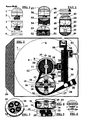
- FIG. 1 shows the block diagram, various forms of positioning with focalization, selective of one or more lenses, hemispherical, fresnel, semi-cylindrical, according to the kind of focalization required, placed at different distances from the focus of the maximum concentration, with an effect at points for hemispherical lens or straight points for semi-cylindrical or ovoid lenses, suitable for photovoltaic sensors in series on the same line.
- the possibility to assemble with multiple generators of electric energy, in series or parallel, allows to obtain the desired output volts and watts.
- Figure two includes a focused lens (6) with the central device generator of electric energy (12) both for heat reaction and by revelation of thermal photons. It includes a toothed rotor (21,30) rotated by various folding flaps which produce a rotatory push as a consequence of the expansion of the fluid heated by the effect "joules"
- the rotor with the polarized magnets (20) is indirectly highly “Glued” by contact with polarized magnets to a dynamo. It includes a container (24) containing an expansible fluid by heat, and with unidirectional valves for the cooled fluid, produced by a cooler (38) solid or liquid or gas.
- the figure 3 and 4 represent a perspective view of the toothed rotor, in a closed circuit sealed, containing polarized magnets for the indirect connection, isolated with the dynamo Figure 6 represents in a schematic way, a divergent focalization, obtained by a single lens (a) distanced from its focus (B) over the central point of maximum focus (C) oriented in a sub-plain divergent the sunlight, both visible and invisible.
- An underlying cell (10) producing electric energy (of any type) receives the photons, through a diverging focalization point, from the point of maximum focus, included in a container (8) containing a thermo-conductive substance, heated per induction from the device (12) became extremely hot due to the concentric and heating lens through a sealed channel (9) a fluid under pressure (liquid, oily, or gas) that expanding itself, as a consequence of the "joule” effect, flows to the entry (13) feeding a toothed rotor (30) blocked by a unidirectional pin (31) with magnet (32) or spring allowing only one direction of rotation.
- a fluid under pressure liquid, oily, or gas
- the block containing the entire system (7) can also be covered under a microscope, by photovoltaic and painted cells or other systems, generating electric energy of the photons of sun and light by infrared solar etc.. as per directly or indirectly reflection.
- Figure 3 this represents saw-tooth rotor (21,30) at the bottom, with a groove (23) of balls positioning housing (19.22), there are also visible the polarized magnets (20) for the connection to a dynamo that generates electric energy for the rotation with a strong magnetic attraction of the rotor's polarized magnets.
- Figure 4 shows a section of the superior rotor (25) where within the passage (24) containing the heated fluid, we can see the cylindrical fins (fins or folding not drawn) incurred by the balls in their place(16).
- Figure 5 shows a central pin (22) for the positioning of the rotor to the external container (25) that encloses all the rotating closed-loop system.
- Figure 6 presents a lens (A) focusing the photons in the point (B) and further to the focal length, different from the central point of maximum focalization, the photons are divergent opening themselves in a way less concentrated in the point (C). This is to avoid that an excessive heat can destroy any component, at the base of the system.
- the Figure 1 shows some formal variation and positioning of multiple lenses (1, 3,4,5) (57.56) placed at different distance from the main focus (54.55) for an attenuation of the concentrated energy power, produced by one or more lenses (51, 52.53 of different forms, both hemispherical and cylindrical (47.48), with a straight concentration of lenses focus of the lens, with one or more planar slopes, illuminating one or more suitable devices (of any kind), placed in series or parallel and capable of generating electric energy.
Abstract
A hybrid solar concentrator for electric power generation comprising one (6) or more concentrating lenses (56.57) with different forms (1.3,4,5,40,45,47,48,49,55) placed at various distances between themselves (46,49,52) with different focal lengths and converging the energy of photons onto a central device (11) (liquid, oily or gaseous) (12,41), comprising a heater of a fluid (liquid, oily or gaseous) (10,12) placed in a sealed central circuit and under pressure (9,58), which expands as a result of the heat obtained from the concentrating lenses, flowing into fluid conduit (13) pushing a rotor with unidirectional motion (30) comprising a rotating magnetic or spring pin (31,32) rotating in one direction and held in place (closed-circuit and under pressure), through more positioning balls (16). Said heated fluid flowing through unidirectional valves (28,29,34,35) towards a special sealed container (38) at solid state, liquid or gas, acting as cooler with filling valves (39,53). The cooled fluid shrinks and re-enters, through unidirectional valves (34,35), the central container (9), closing the fluid circuit and being heated up again to repeat the cycle of thrust of the rotor blades (30). The rotor is connected through the magnetic attraction of polarized magnets (22) to an underlying dynamo, rotating and generating electricity. The system further includes photovoltaic cells sensitive to both to the visible and invisible light (infrared, etc..) and to the heat (7) put under the main lens (6). The device uses both visible and invisible light (infrared, ultraviolet and gamma rays, X,etc..) with various concentration points (40,42.43,45,50).
The advantage of the invention is a compact concentrator generating more energy at lower cost.
The advantage of the invention is a compact concentrator generating more energy at lower cost.
Description
- The present invention relates to a multi-functional generator, "hybrid" and compact of electric energy, obtained by the "concentration" of solar energy photons, with various types of focalizatons (both of visible and invisible light) in the specific points of an innovative device, with "improved characteristics" if compared with other systems, both for its extremely compacted dimensions and for its major electric power "watts", at the lower cost, if compared to the existing photovoltaic and parabolic concentration panels. It's include a "lenticular concentrator," with pre-emption already claimed and released for "microwave" in the patents of Mr. Baldi Franco; for an anti-collision radar system with pre-emption, Italian patent
IT22292A/89 of 7 November, 1989 2 November 1990. EPO 0427131 (A2 18.11,1996 IT 1.29 7.826 and of 28.10,1997 IT 1.29 7.992 EPO 843182 (A2 U.S. 5,991,474 ChineseZL. 97120178.1 97120178.1 IT RE 2006 A 001522 of 15 December 2006 EP 1933163 (A1 ) American Patent:U.S.7.548.190 (B2 ) and Chinese Patent:CN101206261(A ). - The "lenticular" system in the a.m. patents, is also further developed for the photons in the whole spectrum of visible and invisible light (infrared, ultraviolet, X-ray range, etc..) The photons are focused through one or more lenses with different focalizations on a device "target" producing electric energy both through the heat and through the conversion of the photons into energy. The invention is substantially composed by a block generator of electric current, produced with a device (usually liquid, plasma, or gas) located centrally to the fire concentrator of photons, with one or more lenses, allowing to generate electric energy, in the multiple effect produced by one or more of these devices, detectors, as a consequence of warming and of the photons conversion into electric energy, produced by an appropriate device, which in turn heats a liquid under pressure (oily, plasma or gas) for induction, in a closed circuit perfectly sealed and at set pressure, determining the molecular expansion of the same fluid, due to "joule" as a result of the increased temperature, flowing out to particular falling and folding flaps that in order to get the maximum rotation pushing of a toothed rotor and sealed, in a closed circuit under pressure and placed in a close contact; by polarized magnets, with a dynamo, producing electric energy for induction, as a result of the magnetic rotation of the rotor. The device provides several concentrator points of the photons through different angles with different focusing distances, either directly or by reflection "convergent or divergent "from the main focus of one or more lenses. The simultaneous action of heating and conversion of photons into electric energy, added to the dynamo effect, combine to produce a triple generation of electric energy, produced singularly and for the sum of the systems, increasing the total power watts, and if compared to photovoltaic cells with silicon, gallium arsenide, organic material or parabolic concentration,. the invention is smaller than 90%, This key feature is ameliorative, in order to obtain energy electric in a smaller space and with more power watts, enabling innovative solutions and competitive, even for vehicles, trains, satellites, aircraft, ships and for various uses both civilian and military. The invention is described below according to its typical configurations, supplied only for explanation and without limitation, with reference to the attached drawings as per table (I) The Figure one shows the block diagram, various forms of positioning with focalization, selective of one or more lenses, hemispherical, fresnel, semi-cylindrical, according to the kind of focalization required, placed at different distances from the focus of the maximum concentration, with an effect at points for hemispherical lens or straight points for semi-cylindrical or ovoid lenses, suitable for photovoltaic sensors in series on the same line. The possibility to assemble with multiple generators of electric energy, in series or parallel, allows to obtain the desired output volts and watts. Figure two, includes a focused lens (6) with the central device generator of electric energy (12) both for heat reaction and by revelation of thermal photons. It includes a toothed rotor (21,30) rotated by various folding flaps which produce a rotatory push as a consequence of the expansion of the fluid heated by the effect "joules" The rotor with the polarized magnets (20) is indirectly highly "Glued" by contact with polarized magnets to a dynamo. It includes a container (24) containing an expansible fluid by heat, and with unidirectional valves for the cooled fluid, produced by a cooler (38) solid or liquid or gas. The
figure 3 and 4 represent a perspective view of the toothed rotor, in a closed circuit sealed, containing polarized magnets for the indirect connection, isolated with the dynamoFigure 6 represents in a schematic way, a divergent focalization, obtained by a single lens (a) distanced from its focus (B) over the central point of maximum focus (C) oriented in a sub-plain divergent the sunlight, both visible and invisible. With reference to the figures can be observed: InFigure 2 , a concentric lens (6) that focuses sunlight on a "particular device" placed in the maximum central focus (12) with the dual function of transforming photons into electric energy, also through the heating of the device (11.37) with an output with a negative - or positive + polarity according to the functional capabilities of the device. An underlying cell (10) producing electric energy (of any type) receives the photons, through a diverging focalization point, from the point of maximum focus, included in a container (8) containing a thermo-conductive substance, heated per induction from the device (12) became extremely hot due to the concentric and heating lens through a sealed channel (9) a fluid under pressure (liquid, oily, or gas) that expanding itself, as a consequence of the "joule" effect, flows to the entry (13) feeding a toothed rotor (30) blocked by a unidirectional pin (31) with magnet (32) or spring allowing only one direction of rotation. The fluid at high temperature, through the corridor (24) and consequently to the different pressure, push several fins (15) falling or folding (18) in their magnetic place (17) or spring (14) hold in their place by spheres (16) for the output flowing (27) where through a unidirectional check valve (28,29) enters into the container (38) restricting its molecular volume as a result of the cooling induced by a cooler (33) containing gas or liquid, or solid-components. The cooled fluid is directed through a magnetic valve (34) or spring (35) to a unidirectional valve (36) and then again re inserted in the container (9) repeating the rotatory cycle, as a consequence of heating and cooling fluid. The release of the fluid and of cooling liquid or gas, is through the valves (39,53,58). The block containing the entire system (7) can also be covered under a microscope, by photovoltaic and painted cells or other systems, generating electric energy of the photons of sun and light by infrared solar etc.. as per directly or indirectly reflection.Figure 3 , this represents saw-tooth rotor (21,30) at the bottom, with a groove (23) of balls positioning housing (19.22), there are also visible the polarized magnets (20) for the connection to a dynamo that generates electric energy for the rotation with a strong magnetic attraction of the rotor's polarized magnets.Figure 4 shows a section of the superior rotor (25) where within the passage (24) containing the heated fluid, we can see the cylindrical fins (fins or folding not drawn) incurred by the balls in their place(16).Figure 5 shows a central pin (22) for the positioning of the rotor to the external container (25) that encloses all the rotating closed-loop system.Figure 6 presents a lens (A) focusing the photons in the point (B) and further to the focal length, different from the central point of maximum focalization, the photons are divergent opening themselves in a way less concentrated in the point (C). This is to avoid that an excessive heat can destroy any component, at the base of the system. The principle of multiple focalizations, is shown with the lenses (40.45) placed in opposition between themselves, in order to receive the sunlight and the other light from the infrared, coming from the same or different direction. You can see the double concentrator effect with focal divergence (41) of maximum multi-directional concentration (44) composed by one or more lenses (49). TheFigure 1 , shows some formal variation and positioning of multiple lenses (1, 3,4,5) (57.56) placed at different distance from the main focus (54.55) for an attenuation of the concentrated energy power, produced by one or more lenses (51, 52.53 of different forms, both hemispherical and cylindrical (47.48), with a straight concentration of lenses focus of the lens, with one or more planar slopes, illuminating one or more suitable devices (of any kind), placed in series or parallel and capable of generating electric energy.
Claims (10)
- A Closed-Circuit Device characterized by an innovative generator of electric energy, hybrid and compact with extremely reduced dimensions, with pre-emption already claimed and released for her "lenticular concentration" in the "microwaves" of the patent of the Italian inventor Baldi Franco; for a anti-collision radar system with pre-emption, Italian patent IT22292A/89 of the 07 November 1989. European Patent of 02 November 1990. EPO 0427131 (A2) and of 18,11,1996 IT 1,29 7,826 and of 28,10,1997 IT 1,29 7,992. with release of European patent EPO 843182(A2) American US 5,991,474 Chinese ZL 97120178,1 with further improvements in the patent IT Re 2006 A. 001522 of 15 December 2006, European patent EP 1933163 (A1) American US Patent 7,54 8,190 (B2) and Chinese Patent CN 101206261 (A.) that includes a central focalization of the photons of the visible and invisible light in direct or convergent way, divergent or of reflex, through one or more lenses focusing a semi-sphere, fresnel, semi-cylindrical or ovoid (1,3,4,5.40.45, ,47,48.56,57) put to different distances between themselves, with different position in the space (41,46) frontal, upon, under or lateral, from the focus produced by the focused photons. It includes "any device" placed to on the focus centre, at the solid, liquid or gaseous state, (12) "able to convert" the photons concentrated on itself (from one or more lenses), producing electric energy, through the double function, both of the photovoltaic detection, that through the heating of the central component (10) placed under the heater (12) with production (11,37) of electric energy with a positive or negative polarity according to the system requirements.
- Characterized as per claim 1. that the device (11,12) heated by the focused photons (of one or more lenses), heats for induction any substance (9) thermo-conductor, (transparent or less) containing an under pressure fluid, liquid or gaseous thermo expandable (10), contained into a container (8) toward channel (10) with inlet valves of the cold fluid, magnet working by magnet or by spring (35,36) All closed and sealed with fixed pressure, (9,12,24)
- Claim characterized by the fact of an unidirectional rotor (30) immersed in the expandable fluid with closed circuit, it is located in its place by the cylinder (22,) it includes serrated teeth with appropriate form, allowing only unidirectional rotation, starting from the block or a pin (31) with magnetic or spring loading (32) Claim characterized by cylindrical flaps (15) with supporting spheres (16) or with other form, (rigid or flexible fan), them reenter and alternatively go out the rotor, as a result of magnets (17) or springs (14) set on spheres of positioning (16) in her own river bed (22) receiving the heated fluid to pressure, through the entrance (13) it crosses the corridor (24) for "effect Joule" of molecular expansion, consequent to the heat of the device (11,12) The alternating potential "warm - cold", through unidirectional valves (35,36,28,29) it produces a different pressure, inducing the fins of the rotor to an unidirectional rotator motion, for then to flow out to the exit (27) with opportune selective valves (28,29) to a circuit cooler
- Claim characterized, by cylindrical fins (15) with spheres of support (16) or of other form, (to rigid or flexible fan), they reenter and they alternatively go out of the rotor, because of magnets (17) or springs (14) set on positioning spheres (16) in its channel (22) receiving the heated fluid under pressure, through the entry (13) that pass through the channel (24) as a result of "Joule" effect with molecular expansion, as a consequence of the device heating (11,12) The alternating potential "hot - cold", through unidirectional valves (35,36,28,29) produces a different pressure, inducing the rotor flaps to an unidirectional rotatory motion, in order to flow out by the exit (27) with appropriate selective valves (28,29) to a cooler circuit
- Claim characterized by a sealed container (33) to the solid state, liquid or with cooling gas. The system with filling valves (39,53, 58) repeats its own functional cycle by impulses further to the rhythmic unidirectional expansion of the fluid, cooling the heated fluid coming from the rotor. The lower pressure of the cooled fluid (35) as a result of the molecular narrowing, induced by the thermal shock of the cooler (38), it allows the working of an innovative closed-circuit generator of electric energy, with extremely compacted dimensions and miniaturized to the inside and not to the outside, as others thermic reaction systems.
- Claim characterized by the innovative fact, that The rotor is very close to polarized magnets (20) that provides, by contact "pasting" (as a result of the strong magnetic attraction) to rotate a dynamo, generating electric energy, "pasted" to it from the strong magnetic attraction, but isolated, from the circuit in order to avoid dispersions of the fluid under pressure.
- Claim characterized by several innovative features, of electric energy generation, through one or more cell sensors (9) set in various positions, and able to transform into electric energy the whole spectrum of the visible and invisible light and the thermic radiation, (infrared) direct or indirect or divergent, produced by the focus concentrator of one or more lenses, with output of electric energy (37) with positive (+) or negative (-) polarity, originated by one or more PV photovoltaic cells of any type, placed on various plans (7,42,43,50,51,52,53) in different positions of the system, placed above , under, or lateral (42,43,44,50,) with one or more lenses (49,53,56,57) at different distance (46,53) of focusing (40,41,) or positioning (41,49,) straight (1,6,45,47,49,52,57,) or inverted (3,48) or of different forms (4,5) not limitative, frontally set under (or above or lateral) the component (2,12,41) with different focalizations. Including hemispherical lenses, semi-cylindrical or ovoid (47,48) more or less elongated, and set at adjustable distance (46) from the central focus, of the focalization, in "rectilinear" way and not only "Punctiform" of the hemispherical focalization or fresnel etc.
- Claim characterized by one or more electric energy generators placed in series or parallel, to increase the produced power volt - watt. Through photovoltaic and thermal sensors (of any type), able to produce electric energy, both through the heat by conversion of the photons of the visible and invisible light, alone and also in both ways. through coaxial sensory components, adjacent and placed in series and/or in parallel (41,49,52,) under or above the maximum focalization, also in divergent way or of reflex FIG. 6 (A,B,C,) as per claims (1,7) set with same disposition, for one or more lenses with variable divergent focalization, convergent or by reflex.
- Claim characterized by the fact that the system results hybrid and multivalent, as it assembles in a reduced space, more electric energy generation sources, with possibility to produce more generators of various models and functions, exploiting a single or more claims of the whole brevet assembled in an only multifunctional generator, in order to reach the maximum power watt, but with extremely reduced and compacted dimensions. Comprising one or more outputs with different voltage and energy power watt positive or negative, in continued or alternated current.
- Claim characterized by the fusion of more innovative characteristic, able to build a range of different generators of electric energy with reduced dimensions of 90% for civil and military uses, for vehicles of any kind travelling on rubber and rails, for spatial use, sea or earthling, for satellites, airplanes, ships, etc. that need renewable and not polluting electric energy generation at low cost, and with minimum encumbrance dimension.
Applications Claiming Priority (1)
| Application Number | Priority Date | Filing Date | Title |
|---|---|---|---|
| IT001643A ITMI20111643A1 (en) | 2011-09-13 | 2011-09-13 | LENTICULAR ELECTRIC CURRENT GENERATOR WITH CONCENTRATION OF PHOTONS WITH HYBRID THERMAL REACTION AND COMPACT TO DIFFERENT FOCUSING OF VISIBLE AND INVISIBLE LIGHT |
Publications (1)
| Publication Number | Publication Date |
|---|---|
| EP2571064A1 true EP2571064A1 (en) | 2013-03-20 |
Family
ID=44898872
Family Applications (1)
| Application Number | Title | Priority Date | Filing Date |
|---|---|---|---|
| EP11405340A Withdrawn EP2571064A1 (en) | 2011-09-13 | 2011-10-21 | Hybrid solar concentrator comprising concentrating means, a photovoltaic device and a thermal device for producing electricity |
Country Status (2)
| Country | Link |
|---|---|
| EP (1) | EP2571064A1 (en) |
| IT (1) | ITMI20111643A1 (en) |
Cited By (2)
| Publication number | Priority date | Publication date | Assignee | Title |
|---|---|---|---|---|
| CN105207603A (en) * | 2015-09-29 | 2015-12-30 | 成都聚合科技有限公司 | Special adhesive strip for concentrating solar module |
| CN110301089A (en) * | 2017-01-03 | 2019-10-01 | 沙特阿拉伯石油公司 | Safeguard solar energy module |
Citations (10)
| Publication number | Priority date | Publication date | Assignee | Title |
|---|---|---|---|---|
| EP0427131A2 (en) | 1989-11-07 | 1991-05-15 | I.E.G. INDUSTRIE ELETTRONICHE GUGLIONESI S.r.l. | Directive radar antenna with electromagnetic energy compression, for telecommunications |
| EP0843182A2 (en) | 1996-11-18 | 1998-05-20 | Franco Baldi | Obstacle sensor operating by collimation and focusing of the emitted wave |
| GB2321338A (en) * | 1997-01-18 | 1998-07-22 | Peter King | A differential voltage cell |
| IT1297826B1 (en) | 1997-12-30 | 1999-12-20 | Luigi Ture | MONOBLOCK COVERING FOR LADLES, PAN AND SIMILAR CONTAINERS USED IN THE STEEL INDUSTRY. |
| IT1297992B1 (en) | 1997-10-28 | 1999-12-20 | Franco Baldi | Millimetre wave obstacle sensor - operates as signal transceiving antenna with optimum image definition |
| US20070289622A1 (en) * | 2006-06-19 | 2007-12-20 | Lockheed Martin Corporation | Integrated solar energy conversion system, method, and apparatus |
| EP1933163A1 (en) | 2006-12-15 | 2008-06-18 | Franco Baldi | Improvements to an obstacle sensor operating by collimation and focusing of the emitted wave |
| US20100037931A1 (en) * | 2008-08-18 | 2010-02-18 | Chin-Kuang Luo | Method and Apparatus for Generating Electric Power Using Solar Energy |
| WO2010053997A1 (en) * | 2008-11-04 | 2010-05-14 | Eaton Corporation | Combined solar/thermal (chp) heat and power for residential and industrial buildings |
| US20110088755A1 (en) * | 2009-10-15 | 2011-04-21 | Robert Sun | Mobile solar power generator |
-
2011
- 2011-09-13 IT IT001643A patent/ITMI20111643A1/en unknown
- 2011-10-21 EP EP11405340A patent/EP2571064A1/en not_active Withdrawn
Patent Citations (13)
| Publication number | Priority date | Publication date | Assignee | Title |
|---|---|---|---|---|
| EP0427131A2 (en) | 1989-11-07 | 1991-05-15 | I.E.G. INDUSTRIE ELETTRONICHE GUGLIONESI S.r.l. | Directive radar antenna with electromagnetic energy compression, for telecommunications |
| EP0843182A2 (en) | 1996-11-18 | 1998-05-20 | Franco Baldi | Obstacle sensor operating by collimation and focusing of the emitted wave |
| US5991474A (en) | 1996-11-18 | 1999-11-23 | Baldi; Franco | Obstacle sensor operating by collimation and focusing of the emitted wave |
| GB2321338A (en) * | 1997-01-18 | 1998-07-22 | Peter King | A differential voltage cell |
| IT1297992B1 (en) | 1997-10-28 | 1999-12-20 | Franco Baldi | Millimetre wave obstacle sensor - operates as signal transceiving antenna with optimum image definition |
| IT1297826B1 (en) | 1997-12-30 | 1999-12-20 | Luigi Ture | MONOBLOCK COVERING FOR LADLES, PAN AND SIMILAR CONTAINERS USED IN THE STEEL INDUSTRY. |
| US20070289622A1 (en) * | 2006-06-19 | 2007-12-20 | Lockheed Martin Corporation | Integrated solar energy conversion system, method, and apparatus |
| EP1933163A1 (en) | 2006-12-15 | 2008-06-18 | Franco Baldi | Improvements to an obstacle sensor operating by collimation and focusing of the emitted wave |
| CN101206261A (en) | 2006-12-15 | 2008-06-25 | 佛朗哥·巴尔迪 | Improvements to an obstacle sensor operating by collimation and focusing of the emitted wave |
| US7548190B2 (en) | 2006-12-15 | 2009-06-16 | Franco Baldi | Obstacle sensor operating by collimation and focusing of the emitted wave |
| US20100037931A1 (en) * | 2008-08-18 | 2010-02-18 | Chin-Kuang Luo | Method and Apparatus for Generating Electric Power Using Solar Energy |
| WO2010053997A1 (en) * | 2008-11-04 | 2010-05-14 | Eaton Corporation | Combined solar/thermal (chp) heat and power for residential and industrial buildings |
| US20110088755A1 (en) * | 2009-10-15 | 2011-04-21 | Robert Sun | Mobile solar power generator |
Cited By (3)
| Publication number | Priority date | Publication date | Assignee | Title |
|---|---|---|---|---|
| CN105207603A (en) * | 2015-09-29 | 2015-12-30 | 成都聚合科技有限公司 | Special adhesive strip for concentrating solar module |
| CN110301089A (en) * | 2017-01-03 | 2019-10-01 | 沙特阿拉伯石油公司 | Safeguard solar energy module |
| CN110301089B (en) * | 2017-01-03 | 2022-08-09 | 沙特阿拉伯石油公司 | Maintaining solar modules |
Also Published As
| Publication number | Publication date |
|---|---|
| ITMI20111643A1 (en) | 2013-03-14 |
Similar Documents
| Publication | Publication Date | Title |
|---|---|---|
| Thirunavukkarasu et al. | An experimental study on energy and exergy performance of a spiral tube receiver for solar parabolic dish concentrator | |
| US9705449B2 (en) | Effective and scalable solar energy collection and storage | |
| Han et al. | Parametric analysis of a hybrid solar concentrating photovoltaic/concentrating solar power (CPV/CSP) system | |
| Lertsatitthanakorn et al. | Electricity generation from a solar parabolic concentrator coupled to a thermoelectric module | |
| Chavez Urbiola et al. | Investigation of solar hybrid electric/thermal system with radiation concentrator and thermoelectric generator | |
| Maiti et al. | Performance of a silicon photovoltaic module under enhanced illumination and selective filtration of incoming radiation with simultaneous cooling | |
| Muthu et al. | Solar parabolic dish thermoelectric generator with acrylic cover | |
| ES2734191T3 (en) | Double stage parabolic concentrator | |
| Skouri et al. | Optical, geometric and thermal study for solar parabolic concentrator efficiency improvement under Tunisia environment: A case study | |
| Bamroongkhan et al. | Experimental performance study of a solar parabolic dish photovoltaic-thermoelectric generator | |
| Gürel | Exergetic assessment of a concentrated photovoltaic thermal (CPV/T) system | |
| Pakhare et al. | Experimental performance evaluation of a parabolic solar dish collector with nanofluid | |
| EP2571064A1 (en) | Hybrid solar concentrator comprising concentrating means, a photovoltaic device and a thermal device for producing electricity | |
| AU2013241067A1 (en) | Linear solar energy collector system and solar power generator system | |
| Shanmugam et al. | Mathematical modeling of thermoelectric generator driven by solar parabolic dish collector | |
| Maslamani et al. | Development of solar thermoelectric generator | |
| Newton | Concentrated Solar Thermal Energy System | |
| Sridhar et al. | Performance of cylindrical parabolic collector with automated tracking system | |
| KR20230107193A (en) | Generator using thermoelectic element and eco-friendly solar power generation system having the same | |
| EP2878898A1 (en) | Solar ray heat conversion device and solar heat power generating system using same | |
| Arunasalam et al. | Thermal performance analysis on solar integrated collector storage | |
| Nyandang et al. | The Effect of Cooling Method in Parabolic Solar Dish Concentrator | |
| Limboonruang et al. | Experimental investigation of a locally fabricated low-cost solar parabolic trough in Thailand | |
| Ghazouani et al. | Thermal study of the solar parabolic concentrator | |
| anak Nyandang et al. | An Experimental Study of the Effect of Cooling Method in Parabolic Solar Dish Concentrator for Power Generation using Thermoelectric Generator |
Legal Events
| Date | Code | Title | Description |
|---|---|---|---|
| PUAI | Public reference made under article 153(3) epc to a published international application that has entered the european phase |
Free format text: ORIGINAL CODE: 0009012 |
|
| AK | Designated contracting states |
Kind code of ref document: A1 Designated state(s): AL AT BE BG CH CY CZ DE DK EE ES FI FR GB GR HR HU IE IS IT LI LT LU LV MC MK MT NL NO PL PT RO RS SE SI SK SM TR |
|
| AX | Request for extension of the european patent |
Extension state: BA ME |
|
| STAA | Information on the status of an ep patent application or granted ep patent |
Free format text: STATUS: THE APPLICATION IS DEEMED TO BE WITHDRAWN |
|
| 18D | Application deemed to be withdrawn |
Effective date: 20130921 |