EP2571040A2 - Sealing structure of terminal member, electromagnetic relay, and method of manufacturing the same - Google Patents
Sealing structure of terminal member, electromagnetic relay, and method of manufacturing the same Download PDFInfo
- Publication number
- EP2571040A2 EP2571040A2 EP20120005272 EP12005272A EP2571040A2 EP 2571040 A2 EP2571040 A2 EP 2571040A2 EP 20120005272 EP20120005272 EP 20120005272 EP 12005272 A EP12005272 A EP 12005272A EP 2571040 A2 EP2571040 A2 EP 2571040A2
- Authority
- EP
- European Patent Office
- Prior art keywords
- terminal
- base
- press
- portions
- fitted
- Prior art date
- Legal status (The legal status is an assumption and is not a legal conclusion. Google has not performed a legal analysis and makes no representation as to the accuracy of the status listed.)
- Granted
Links
- 238000007789 sealing Methods 0.000 title claims abstract description 66
- 238000004519 manufacturing process Methods 0.000 title claims abstract description 9
- 238000000034 method Methods 0.000 claims description 9
- 238000005520 cutting process Methods 0.000 claims description 2
- 238000004080 punching Methods 0.000 claims 1
- 238000005516 engineering process Methods 0.000 abstract 1
- XEEYBQQBJWHFJM-UHFFFAOYSA-N Iron Chemical compound [Fe] XEEYBQQBJWHFJM-UHFFFAOYSA-N 0.000 description 89
- 229910052742 iron Inorganic materials 0.000 description 36
- 239000003795 chemical substances by application Substances 0.000 description 33
- 238000009434 installation Methods 0.000 description 12
- 230000004907 flux Effects 0.000 description 6
- 238000009413 insulation Methods 0.000 description 6
- 229920003002 synthetic resin Polymers 0.000 description 6
- 239000000057 synthetic resin Substances 0.000 description 6
- 238000004804 winding Methods 0.000 description 6
- 239000000463 material Substances 0.000 description 5
- 239000000696 magnetic material Substances 0.000 description 4
- 238000003825 pressing Methods 0.000 description 4
- 230000008569 process Effects 0.000 description 4
- 238000000418 atomic force spectrum Methods 0.000 description 3
- 230000008859 change Effects 0.000 description 3
- 238000012986 modification Methods 0.000 description 3
- 230000004048 modification Effects 0.000 description 3
- 238000003466 welding Methods 0.000 description 3
- 239000004020 conductor Substances 0.000 description 2
- 230000003247 decreasing effect Effects 0.000 description 2
- 238000003780 insertion Methods 0.000 description 2
- 230000037431 insertion Effects 0.000 description 2
- 238000000465 moulding Methods 0.000 description 2
- RYGMFSIKBFXOCR-UHFFFAOYSA-N Copper Chemical compound [Cu] RYGMFSIKBFXOCR-UHFFFAOYSA-N 0.000 description 1
- 229910052802 copper Inorganic materials 0.000 description 1
- 239000010949 copper Substances 0.000 description 1
- 230000005389 magnetism Effects 0.000 description 1
- 230000000717 retained effect Effects 0.000 description 1
Images


Classifications
-
- H—ELECTRICITY
- H01—ELECTRIC ELEMENTS
- H01H—ELECTRIC SWITCHES; RELAYS; SELECTORS; EMERGENCY PROTECTIVE DEVICES
- H01H11/00—Apparatus or processes specially adapted for the manufacture of electric switches
-
- H—ELECTRICITY
- H01—ELECTRIC ELEMENTS
- H01H—ELECTRIC SWITCHES; RELAYS; SELECTORS; EMERGENCY PROTECTIVE DEVICES
- H01H50/00—Details of electromagnetic relays
- H01H50/02—Bases; Casings; Covers
- H01H50/023—Details concerning sealing, e.g. sealing casing with resin
-
- H—ELECTRICITY
- H01—ELECTRIC ELEMENTS
- H01H—ELECTRIC SWITCHES; RELAYS; SELECTORS; EMERGENCY PROTECTIVE DEVICES
- H01H50/00—Details of electromagnetic relays
- H01H50/14—Terminal arrangements
-
- H—ELECTRICITY
- H01—ELECTRIC ELEMENTS
- H01H—ELECTRIC SWITCHES; RELAYS; SELECTORS; EMERGENCY PROTECTIVE DEVICES
- H01H9/00—Details of switching devices, not covered by groups H01H1/00 - H01H7/00
- H01H9/30—Means for extinguishing or preventing arc between current-carrying parts
- H01H9/44—Means for extinguishing or preventing arc between current-carrying parts using blow-out magnet
- H01H9/443—Means for extinguishing or preventing arc between current-carrying parts using blow-out magnet using permanent magnets
-
- Y—GENERAL TAGGING OF NEW TECHNOLOGICAL DEVELOPMENTS; GENERAL TAGGING OF CROSS-SECTIONAL TECHNOLOGIES SPANNING OVER SEVERAL SECTIONS OF THE IPC; TECHNICAL SUBJECTS COVERED BY FORMER USPC CROSS-REFERENCE ART COLLECTIONS [XRACs] AND DIGESTS
- Y10—TECHNICAL SUBJECTS COVERED BY FORMER USPC
- Y10T—TECHNICAL SUBJECTS COVERED BY FORMER US CLASSIFICATION
- Y10T29/00—Metal working
- Y10T29/49—Method of mechanical manufacture
- Y10T29/49002—Electrical device making
- Y10T29/4902—Electromagnet, transformer or inductor
Definitions
- the present invention relates to a sealing structure of a terminal member, an electromagnetic relay, and a method of manufacturing the same.
- a sealing structure of a terminal member there is a well-known structure in which a common terminal is folded in half and it is inserted into a through-hole of a base, and the through-hole is then sealed (for example, refer to Japanese Patent No. 3213978 ).
- This terminal structure is likely to have a problem in that an air gap is formed in a bent portion of the terminal because the terminal is folded in half. Accordingly, in order to solve this problem, a line-shaped space passage is formed in the middle of the terminal and is then filled with a sealing agent beforehand.
- the present invention has been devised to solve the problems described above, and an object thereof is to provide a sealing structure of a terminal member which has a simple structure, is easy to manufacture, and does not increase cost, an electromagnetic relay, and a method of manufacturing the same.
- a sealing structure of a terminal member which is to be press-fitted into a terminal hole formed in a base
- the terminal member includes a press-fitted portion which is to be press-fitted into the terminal hole, and a terminal portion extending from the press-fitted portion and protruding from the base
- the terminal portion is configured by folding a plate-like body such that folded portions overlap a planar portion, the folded portions have cut-away portions at edges thereof near the press-fitted portion, the cut-away portions extending from the base, and a sealing agent can be injected into the terminal hole via the cut-away portions.
- the sealing agent can be naturally injected into the terminal hole via the cut-away portions extending from the base. Therefore, the terminal hole can be efficiently sealed and sealing performance can be enhanced.
- the terminal portion has a simple structure which is formed by folding a plate-like body such that the folded portions overlap a planar portion and by providing cut-away portions to the folded portions. Therefore, the terminal portion can be manufactured at low cost.
- the terminal portion may be structured such that both sides of the plate-like body are folded over to overlap the planar portion, and the folded portions have the cut-away portions at their opposite sides, respectively.
- an operation of charging the sealing agent via the cut-away portions can be performed at a border area between the planar portion and each of the folded portions, so that the terminal hole can be more smoothly sealed in a stable condition.
- the cut-away portion preferably has an inclined edge that unites a portion of the cut-away portion extending from the base with the inside of the terminal hole.
- This structure allows the sealing agent being injected into the terminal hole via the cut-away portions to smoothly flow over a short distance along the inclined edge.
- the cut-away portions are preferably formed by cutting away opposing sides of both the folded portions in a portion extending from the base so that the cut-away portions and the planar portion form a sealing agent reservoir.
- This structure allows a surplus sealing agent, which cannot be retained in the terminal hole and thus overflows, to be solidified in the sealing agent reservoir, so that the surplus sealing agent is prevented from negatively affecting other portions.
- portions which form the sealing agent reservoir may be formed to be broader than the other portions.
- This structure increases flow-resistance of the sealing agent at locations other than the terminal hole, so that the flow of the sealing agent to the other locations can be reliably stopped.
- the terminal member preferably includes a contact piece portion protruding from a side of the base opposite to a side from which the terminal portion protrudes.
- the contact piece is elastically deformable and has a contact at a leading end thereof.
- the plate-like body is used in its original form at the contact piece portion and is folded at the terminal portion so that desired thickness and strength can be obtained.
- an electromagnetic relay with a fixed contact piece which has any of the above-mentioned structures.
- a terminal portion includes a planar portion and folded portions which are folded from both sides of a plate-like body so as to overlap the planer portion, in which the folded portions has cut-away portions extending from a base. Accordingly, the terminal portion has a simple structure and can be manufactured at low cost. Moreover, a sealing agent can be effectively injected into a terminal hole via the cut-away portions so that the sealing performance can be significantly enhanced.
- Figs. 1 to 5 illustrate an electromagnetic relay according to an embodiment of the present invention.
- an electromagnet block 2 a contact switching unit 3, and a movable iron piece 4 are installed on a base 1, and the whole structure is encased in a case 5.
- the base 1 is rectangular in a plan view and is formed by performing a molding process with a synthetic resin material as shown in Figs. 6A and 6B .
- the base 1 there are two installation areas including a first installation portion 6 and a second installation portion 7 arranged in a longitudinal direction.
- X-axis the longitudinal direction running along a longer side
- Y-axis a lateral direction running along a shorter side
- Z-axis a direction running along the height
- the first installation portion 6 is an area reserved for installation of the electromagnet block 2 to be described later and is configured in a manner that a supporting concave portion 10 is formed in a recess 9 surrounded with a first periphery wall 8 formed on an upper surface of the base 1 and with a second installation portion 7.
- a pair of coil terminal holes 11 that completely pass through the bottom of the recess 9 from the upper side to the lower side are formed at both sides of the supporting concave portion 10 in the lateral direction of the base 1 (the direction of YY'), respectively.
- concave sealing portions each with four tapered side surfaces, are formed such that each concave sealing portion is formed in a surrounding area of a location where the coil terminal hole 11 is open.
- a guide portion 12 is formed near the supporting concave portion 10 (in the longitudinal direction of the base 1).
- the guide portion 12 includes a pair of guide walls 13 which are formed to correspond to the shorter-side direction (the direction of YY'), and an insulation wall 14 that connects the pair of guide walls 13.
- Guide grooves 15 each of which vertically extends are formed in opposing surfaces of the guide walls 13, respectively. Both sides of a yoke 41 to be described later are guided by both the guide grooves 15.
- a concave guide portion 16 is formed at a center portion of an area surrounded with the guide walls 13 and the insulation wall 14.
- a to-be-guided portion 50 of a hinge spring 44 to be described later is located in the concave guide portion 16.
- the second installation portion 7 is an area reserved for the contact switching unit 3, and a plinth 17 having the same height as the first periphery wall 8 of the first installation portion 6 is formed in the second installation portion 7.
- a slit-like first terminal hole 18 extending in the direction of YY' is formed.
- the first terminal hole 18 passes through the bottom of the base 1 only at two locations where communicating portions 19 are formed, and a movable contact piece 52 to be described later is press-fitted into the first terminal hole 18.
- a second periphery wall 20 is formed at three sides of the plinth 17 except for one side that is near the first installation portion.
- a part of the second periphery wall 20 which is disposed on the side of the X' direction side is relatively thick and has a pair of slit-like second terminal holes 21 which extend and are arranged in the direction of YY'.
- Each second terminal hole 21 is formed by opening the bottom surface of the concave portion which is formed in the upper surface of the base 1 while leaving a middle portion of the bottom surface of the concave portion.
- Each of the second terminal holes 21 is located near the short side of the base 1 in the X' direction, and a distance between the opening in the lower surface and the shorter side is small. Moreover, as illustrated in Fig. 14 , a recess 1 a extending from the position of the opening of each second terminal hole 21 to the short side of the base 1 is formed in the lower surface of the base 1.
- the bottom surface of the recess 1 a is tapered like a mountain, that is, the recess 1 a is deepest at the center thereof.
- Electromagnet block 2
- the electromagnet block 2 is a structure formed by winding a coil 24 around an iron core 22 using a spool 23.
- the iron core 22 is a bar of an electromagnetic material.
- a flange-like magnetic pole portion 25 is formed at a lower end of the iron core 22 and the yoke 41 is fastened to an upper end of the iron core 22.
- the spool 23 is obtained by performing a molding process with a synthetic resin material, and includes a cylindrical trunk 27 having a center hole 26 formed therein and flanges (an upper-end flange 28 and a lower-end flange 29) formed at an upper end and a lower end of the cylindrical trunk 27, respectively:
- a relief groove 30 is formed in an upper surface of the upper-end flange 28 and the center hole 26 is open. An end of the yoke 41 to be described later is disposed in the relief groove 30.
- the center hole 26 is also open in the lower-end flange 29 and the iron core 22 can be inserted into the center hole 26 from the lower-end flange 29.
- Terminal attachment portions 31 are provided at both sides of the lower-end flange 29, respectively and terminal holding holes 32 are formed there, respectively.
- Coil terminals 36 to be described later are press-fitted in and fixed to the terminal holding holes 32, respectively.
- Step portions 33 are formed on both sides of an end of the terminal attachment portion 31, respectively, and coil winding portions 39 of the coil terminals 36 which are press-fitted in the terminal holding holes 32 to be fixed project over the step portions 33, respectively.
- the lower-end flange 29 has a guide groove 34 that communicates with one of the step portions 33 via a way from the trunk 27 to a side end surface thereof.
- An end of the coil 24 (a beginning end of turns of the coil 24) wound around the trunk 27 is disposed in the guide groove 34, and the coil 24 is wound around the coil winding portion 39 of the coil terminal 36 which projects over the step portion 33.
- a pair of guide protrusions 35 are provided in the bottom surface of the lower-end flange 29 at a predetermined interval. The guide protrusions 35 serve to position the spool 23, in other words, the electromagnet block 2 with respect to the base 1 by being put in the supporting concave portions 10 of the base 1.
- the coil terminal 36 is a plate-like body of an electrically conductive material, and its lower end portion is tapered to the bottom such that the width and thickness are gradually decreased toward the bottom.
- the coil terminal 36 has a press-fitted portion 37 which is expanded from one surface of the plate-like body through a press-working process at an upper end portion thereof, and a portion of the coil terminal 36 on the upper side of the press-fitted portion 37 is formed as a wide width portion 38.
- the coil winding portion 39 projects from one end of the wide width portion 38.
- the coil 24 is wound around the trunk 27 of the spool 23, and an insulation sheet 40 is attached to the outer circumferential surface of the coil 24.
- One end of the coil 24 is arranged in the guide groove 34 of the spool 23, and the coil 24 is then wound around the trunk 27 of the spool 23. After that, both ends of the coil 24 are wound around the coil winding portion 39 of the coil terminal 36, and then soldered to be fixed.
- the yoke 41 is fastened to an end of the iron core 22.
- the yoke 41 is made of a magnetic material and has a bent body of a substantial L shape.
- An end of the yoke 41 is provided with an opening 41 a so that an end of the iron core 22 is inserted in the opening 41 a so as to be fastened to the end of the yoke 41.
- the other end of the yoke 41 is a wide width portion, and protruding portions 42 are provided at both sides of a lower end of the wide width portion, respectively.
- the movable iron piece 4 to be described later is located between both the protruding portions 42, and one corner of the protruding portions 42 functions as a fulcrum on which the movable iron piece 4 is movably supported.
- two fastening projections 43 are formed on an outside surface of the yoke 41 and they are arranged on a vertical line.
- a hinge spring 44 is fastened to the middle portion of the yoke 41 by using the projections 43.
- the method of fixing the hinge spring 44 to the yoke 41 is not limited to the fastening, but a different method such as ultrasonic welding, resistance welding, laser welding, or the like may be used.
- the hinge spring 44 includes a joint portion 45 that comes in contact with the outside surface of the middle portion of the yoke 41.
- the joint portion 45 has through-holes 45a at two locations and the projections 43 of the yoke 41 are inserted into the through-holes 45 so as to be fastened.
- the upper side of the joint portion 45 is an elastic contact portion 46 which extends at a predetermined angle as if the elastic contact portion 46 gradually becomes farther from the outside surface of the middle portion of the yoke 41.
- the elastic contact portion 46 is configured to be able to come in contact with a pressing force receiving portion of a card member 65 provided to the movable iron piece 4 to be described later.
- the elastic contact portion 46 alleviates collision noise generated when the movable iron piece 4 returns to a default position.
- the lower side of the joint portion 45 is an elastic support portion 49 which includes a first inclination portion 47 extending at a predetermined angle as if it gradually becomes farther from the outside surface of the middle portion of the yoke 41 and a second inclination portion 48 extending from the first inclination portion 47 at a predetermined angle as if it gradually becomes closer to yoke 41.
- the second inclination portion 48 of the elastic support portion 49 is in pressure-contact with the movable iron piece 4 to be described later so that the movable iron piece 4 is elastically, turnably supported on the elastic support portion 49.
- the lower side of the elastic support portion 49 serves as the to-be-guided portion 50 which extends downward in a vertical direction in a state in which the movable iron piece 4 is elastically supported on the elastic support portion 49.
- the to-be-guided portion 50 is arranged in the concave guide portion 16 formed in the first installation portion 6 of the base 1 and guided by the concave guide portion 16 so that the hinge spring 44 is prevented from being mispositioned.
- the contact switching unit 3 as illustrated in Figs. 4 and 5 , includes the fixed contact pieces 51 and the movable contact piece 52, each of which is obtained by performing press working on an electrically conductive material such as copper.
- the fixed contact piece 51 is an example of the terminal member with the sealing structure according to the present invention, and includes a press-fitted portion 53, a terminal portion 54 extending downward from the press-fitted portion 53, and a contact piece portion 55 extending upward from the press-fitted portion 53.
- the press-fitted portion 53 is provided with expansion portions 56 that are expanded from one surface thereof by using the press working process.
- the press-fitted portion 53 can be press-fitted into the second terminal hole 21 of the base 1 by using the this expansion portions 56.
- the terminal portion 54 is formed by changing a flat panel of an almost rectangular shape connected to a narrow width portion 54b which is formed by arc-shaped notch portions 54a formed at both sides thereof as shown in Fig. 13A into a plate shape shown Fig. 13B by folding over both sides of the almost rectangular flat panel. That is, the terminal portion 54 is a plate-like body including a planar portion 54c connected to the press-fitted portion 53 and folded portions 54d that are folded over to overlap the planar portion 54c.
- the plate-like terminal portion 54 has a smaller width than the press-fitted portion 53 and is deviated from the centerline.
- the terminal portion 54 has a thickness about two times that of the contact piece portion 55 so that enough strength can be secured.
- the notch portions 54a facilitate folding of the folded portions 54d.
- each of the folded portions 54d has a cut-away portion 54i consisting of an inclined edge 54g and an L-shaped edge 54h, in which the inclined edge gradually slops toward the middle portion of the terminal portion with respect to the leading end portion and the L-shaped edge 54h is disposed near the groove 54e.
- the portions extending from the lower surface of the base 1 include the L-shaped edge 54h and part of the inclined edge 54g of the cut-away portion 54i.
- a sealing agent reservoir 54j is formed by the surface of the planar portion 54c and the L-shaped edges 54h, so that the sealing agent is prevented from flowing to the leading end portion of the terminal portion 54.
- the contact piece portion 55 is formed on the opposite side of the terminal portion 54 and misaligned with the terminal portion 54. Since the terminal portion has an overlappingly folded structure, the contact piece portion is allowed to have such a small thickness that enables the contact piece portion to be elastically deformed.
- a middle portion of the contact piece portion 55 is provided with a slit 55a and an upper end portion of the contact piece portion 55 is provided with a through-hole in which the fixed contact 57 is fastened.
- the movable contact piece 52 includes a press-fitted portion 58 and a pair of contact piece portions 59 extending upward from both sides of the press-fitted portion 58, respectively.
- an expansion portion 60 extending in the widthwise direction is formed like in the fixed contact piece 51.
- the expansion portion 60 can be press-fitted into the first terminal hole 18 of the base 1.
- a pair of projections 61 that project downward are respectively formed at both ends of a lower edge of the press-fitted portion 58.
- the contact piece portion 59 is bent at a location near the press-fitted portion 58 and has a through-hole 59a at an upper end portion thereof, and the movable contact 62 is fastened by the through-hole 59a.
- the movable contact piece 52 is arranged such that the movable contact 62 can move closer to and away from the fixed contact 57 of the fixed contact piece 51 which is press-fitted into the second terminal hole 21 in a state in which the press-fitted portion 58 is press-fitted into the first terminal hole 18 of the base 1.
- Movable iron piece 4 The movable iron piece 4 is formed by performing press working on a plate of a magnetic material so that the plate becomes an L shape as shown in Figs. 7 and 8 .
- An end portion of the movable iron piece 4 is a to-be-attracted portion 63 which is to be attracted to the magnetic pole portion 25 of the iron core 22.
- a leading end portion and a base portion of the to-be-attracted portion 63 has a small width, so that an interference between the protruding portions 42 formed in the lower end portion of the yoke 41 and the guide protrusion 35 formed in the bottom surface of the spool 23 can be avoided.
- the other end portion of the movable iron piece 4 is provided with an opening 64.
- the hinge spring 44 passes through the opening 64, and comes in pressure-contact with a corner portion of the to-be-attracted portion 63.
- the other end portion of the movable iron piece 4 has a small width, and the card member 65 is integrally formed with an upper portion of the movable iron piece 4 which is disposed on the upper side of the opening 64.
- the card member 65 is made of a synthetic resin material.
- first protruding portions 66 are formed at both sides of the upper end portion of the movable iron piece 4, respectively and a second protruding portion 67 is formed at an upper side of the first protruding portions 66.
- projection portions 68 On the other surface of the card member 65, projection portions 68 extending in the vertical direction are formed at a predetermined interval in the widthwise direction. Pressing portions 69 which project more than the projection portions 68 are formed at upper ends of the projection portions 68, respectively so that the pressing portions 69 can press the upper ends of the contact piece portion 59 of the movable contact piece 52.
- a shield wall 70 which protrudes more than the other surface and extends downward is formed at a lower end portion of the card member 65.
- the case 5 has a box shape which is open at a lower end as shown in Fig. 2 and is made of a synthetic resin material.
- the case 5 has a sealing hole 71 in a corner of an upper surface. After a fitting portion of the base 1 and the case 5 is sealed, the sealing hole 71 is closed by heat sealing.
- slit-like concave portions 72 are formed at both side portions and a center portion, respectively.
- a recess 73 that is recessed from the upper surface of the case 5 is formed every between the concave portions 72, and a projection 74 is formed at a center portion of the surface of the recess 73.
- An arc-extinguishing member 75 is attached to the case 5 using the concave portions 72 and the recess 73.
- the arc-extinguishing member 75 includes a pair of permanent magnets 76, arranged at a predetermined interval, for extinguishing the arc and a joint member 77, made of a magnetic material, for magnetically connecting these permanent magnets 76.
- the permanent magnets 76 have an almost rectangular parallelepiped shape and are arranged such that opposite sides thereof may have different polarities in a state in which the permanent magnets 76 are attached to the opposite inside walls 78 of the joint member 77.
- the polarities of the opposing surfaces may be set such that the direction of force exerting on the arc current which changes according to the direction of the current flowing at a contact point is directed toward a middle wall 79 of the joint member 77 to be described later.
- the joint member 77 is formed by performing press working on a plate of a magnetic material such that both ends are bent so as to face each other.
- the permanent magnets 76 are attracted and fixed to the inside surfaces of the opposing walls 78, respectively.
- both side portions of the middle wall 79 are cut away at different locations which are nearer opposite ends, respectively, so that middle protruding portions 80 are formed between the opposing walls 78.
- Each of the middle protruding portions 80 serves to shorten a magnetic path by being located in the middle portion between both the opposing walls 78 and protruding between both contact switching positions.
- a closed loop is formed such that the magnetic flux generated from each of the permanent magnets 76 passes the middle wall 79 and each of the opposing walls 78 via the middle protruding portions 80, and returns to the permanent magnets 76.
- the arc-extinguishing member 75 is provided with not only the pair of permanent magnets 76 but also the joint member 77 to magnetically connect the permanent magnets 76. Therefore, the magnetic circuit is formed, and as a result, it becomes difficult for the magnetic flux to leak. Moreover, since the middle protruding portions 80 are provided, the magnetic path can be shortened. Therefore, magnetic efficiency can be improved. Accordingly, even if an arc occurs at the time when the contact is opened or closed, this arc elongates to the sides according to the Fleming's left hand rule, and as a result, the arc is extinguished in a short time.
- the coil 24 is wound around the trunk 27 of the spool 23, and the coil terminal 36 is press-fitted and fixed to the lower-end flange 29. Both ends of the coil 24 are wound around the coil winding portion 39 and soldered. Moreover, the iron core 22 is inserted to pass through the center hole 26 of the spool 23 from the lower end of the spool 23, and the yoke 41 to which the hinge spring 44 is attached beforehand is fastened to the a portion of the iron core 22 which is exposed from the upper end of the spool. As a result, the electromagnet block 2 assembly is completed.
- the movable iron piece 4 is supported in a turnable manner on the lower end of the yoke 41 by using the hinge spring 44. Under this condition, the first protruding portion 66 of the card member 65 which is integrally formed with the movable iron piece 4 can come into contact with the yoke 41, and the elastic contact portion 46 of the hinge spring 44 can move closer to and away from the second protruding portion 67 of the card member 65.
- the electromagnet block 2 to which the movable iron piece 4 is attached, and the contact switching unit 3 is installed in the base 1.
- the coil terminal 36 When installing the electromagnet block 2, the coil terminal 36 is press-fitted into the coil terminal hole 11 of the base 1, and both side portions of the yoke 41 are inserted into the guide grooves 15 of the guide wall 13.
- the guide protrusion 35 In the installed state, the guide protrusion 35 is located in the supporting concave portion 10, and the electromagnet block 2 is positioned on one side thereof in the direction of YY'.
- the lower end surface of the protruding portion 42 of the yoke 41 and the bottom surface of the terminal attachment portion 31 come in contact with the bottom surface of the recesses 9 of the base 1 respectively.
- the press-fitted portion 58 of the movable contact piece 52 is press-fitted into the first terminal hole 18 of the base 1.
- the projection 61 is located in the communicating portion 19
- the installation state of the movable contact piece 52 can be confirmed by viewing the bottom surface of the base 1.
- the pressing portion 69 of the card member 65 which has been installed beforehand comes in pressure-contact with the upper end portion of the movable contact piece 52, and the movable iron piece 4 is positioned at the default position at which the to-be-attracted portion 63 is separated from the magnetic pole portion 25 of the iron core 22 due to the elastic force of the movable contact piece 52.
- the terminal portion 54 of the fixed contact piece 51 is inserted into the second terminal hole 21 of the base 1, and the press-fitted portion 53 is then press-fitted so as to be fixed. Under this condition, the lower edge of the press-fitted portion 53 comes in contact with the partially left bottom surface of the second contact hole 21, so that the dimension of a protruding portion of the terminal portion 54 which protrudes from the base 1 becomes a pre-set value.
- the sealing agent reservoir 54j composed of a part of the inclined edge 54g and the L-shaped edge 54h which is connected to the inclined edge 54g is exposed from the lower surface of the base 1 due to the cut-away portions 54i formed in the terminal portion 54.
- the sealing agent can be injected into the second terminal hole 21 via the sealing agent reservoir 54j.
- the fixed contact piece 51 faces the movable contact piece 52 with a prescribed distance therebetween, and the movable contact 62 can move closer to or away from the fixed contact 57.
- the arc-extinguishing member 75 is installed in the case 5.
- the arc-extinguishing member 75 in the state in which the permanent magnets 76 are attached to the opposing walls 78 of the joint member 77, the opposing walls 78 of the joint member 77, the permanent magnets 76, and the middle protruding portion 80 are inserted into the concave portions 72, respectively formed in the case 5.
- the base 1 is encased in the case 5 in which the arc-extinguishing member 75 has been installed beforehand, and the fitting portion and then each of the terminal holes are sealed.
- the sealing agent may be supplied to the sealing agent reservoir 54j as described above.
- the sealing agent supplied to the sealing agent reservoir 54j flows over a short distance along the inclined edge 54g so as to enter the second terminal hole 21, so that the sealing agent seals up a gap between the second terminal hole 21 and the terminal portion 54.
- the sealing agent since the sealing agent is injected from the sealing agent reservoir 54j exposed from the base 1, the second terminal hole 21 can be reliability filled with the sealing agent.
- the surplus sealing agent since the flow of the surplus sealing agent is blocked by a structure formed by the L-shaped edge 54h of the sealing agent reservoir 54j, the surplus sealing agent does not spread to a portion of the terminal portion 54 which protrudes from the lower surface of the base 1.
- the movable iron piece 4 Under a condition in which the coil 24 is not energized and the electromagnet block 2 is demagnetized, the movable iron piece 4 is located at the default position at which the to-be-attracted portion 63 is separated from the magnetic pole portion 25 of the iron core 22 because the movable iron piece 4 causes the to-be-attracted portion 63 to turn about the fulcrum supported by the yoke 41 by using the elastic force of the movable contact piece 52. Therefore, the movable contact 62 maintains the open state in which the movable contact 62 is separated from the fixed contact 57.
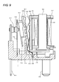
- the to-be-attracted portion 63 of the movable iron piece 4 is attracted to the magnetic pole portion 25 of the iron core 22 and turns against the biasing force of the movable contact piece 52 as shown in Fig. 9 .
- Such an operation allows the movable contact piece 52 to be elastically deformed and allows the movable contact 62 to be in contact with the fixed contact 57 of the fixed contact piece 51.
- the movable iron piece 4 When energizing the coil 24 is stopped and the electromagnet block 2 is demagnetized, the movable iron piece 4 is not attracted by the iron core 22 anymore so that the movable iron piece 4 turns due to the elastomeric force of the movable contact piece 52.
- the second protruding portion 67 formed on the card member 65 of the movable iron piece 4 collides with the elastic contact portion 46 of the hinge spring 44.
- the second protruding portion 67 is made of a synthetic resin so that the elastic contact portion 46 is elastically deformed. However, a contact state of the second protruding portion 67 and the elastic contact portion 46 is obtained within a short time after the movable iron piece 4 starts turning. Accordingly, nearly no collision noise is generated.
- the elastic contact portion 46 is elastically deformed and the first protruding portion 66 made of a synthetic resin comes into contact with the middle portion of the yoke 41. Accordingly, the turning speed of the movable iron piece 4 is reduced, and this also serves to sufficiently suppress generation of the collision noise. In this way, the movable iron piece 4 smoothly returns to the default position without generating the collision noise and the movable contact 62 is separated from the fixed contact 57 and is positioned at an open position.
- the magnetic flux generated from the N pole of each of the permanent magnets 76 runs in a magnetic circuit in which the magnetic flux passes the middle wall 79 via the middle protruding portions 80 of the joint member 77, and returns to the S pole of each of the permanent magnet 76 from the opposing walls 78.
- Each magnetic circuit forms a closed-loop so that nearly zero magnetic flux leaks to surroundings.
- the magnetism can be effectively exerted on the arc generated at the contact switching position, in other words, between the contacts points.
- the magnetic poles of the permanent magnets 76 are set in a manner that the magnetic poles of the opposing surfaces are different so that the direction of the magnetic flux which enables the arc to be deformed toward the middle wall of the joint member 77 can be obtained. That is, the arc can be more certainly extinguished because the arc is deformed toward the middle wall of the joint member 77. Therefore, if the contact switching unit 3 is differently structured from the above manner, the magnetic poles of the permanent magnets 76 may be set in a manner corresponding to such a structure.
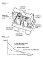
- an operating voltage of the electromagnet block 2 can be adjusted as follows. That is, the operating voltage of the electromagnet block 2 can be controlled by changing the inclination angle of the elastic contact portion 46 of the hinge spring 44. In greater detail, if the inclination angle of the elastic contact portion 46 with respect to the yoke 41 is increased, the position of an operating point can be changed in accordance with a change in the force (attracting force curve) that exerts on the to-be-attracted portion 63 of the movable iron piece 4 due to the magnetic field generated from the magnetic pole portion 25 of the iron core 22 as shown in the graph of Fig. 12 .
- the force needed for a period from the opening of the contacts to the timing at which the elastic contact portion 46 comes into contact with the first protruding portion 66 can be reduced by increasing the inclination angle of the elastic contact portion 46. Accordingly, the operating voltage of the electromagnet block 2 can be controlled such that the attracting force curve can change in a narrower range than that of Fig. 12 .
- the present invention is not limited to the structures described in the embodiment, and can be modified in various ways.
- the sealing agent reservoir 54j is configured by the inclined edge 54g and the L-shaped edge 54h of the folded portions 54d in the above-described embodiment
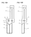
- the L-shaped edge 54h can be changed to a V-shaped edge 54k as shown in Fig. 15A so that the path that guides the sealing agent to the groove 54e can be increased.
- a problem that the sealing agent flows to positions other than the sealing position (mainly the second terminal hole 21) can be more adequately inhibited.
- the cut-away portion 54i can be formed to be broader in a corner portion of the L-shaped edge 54h or the V-shaped edge 54k. According to this structure, an event that the sealing agent flows to positions other than the sealing position can be much more adequately prevented.
- the terminal portion 54 is formed such that the folded portions 54d are folded from both sides in the above-described embodiment, the folded portions 54d are not necessarily folded from both sides. That is, as illustrated in Fig. 15B , the terminal portion may have a structure having only one folded portion which is folded over from one side.
- the sealing structure of a terminal member according to the present invention can be adopted not only in the electromagnetic relay but also in other electronic devices, for example, a switch as long as the electronic devices include an electric switch.
Abstract
Description
- The present invention relates to a sealing structure of a terminal member, an electromagnetic relay, and a method of manufacturing the same.
- Conventionally, as a sealing structure of a terminal member, there is a well-known structure in which a common terminal is folded in half and it is inserted into a through-hole of a base, and the through-hole is then sealed (for example, refer to Japanese Patent No.
3213978 - However, in the conventional sealing structure of a terminal member, there is a problem that the structure is complicated and difficult to manufacture, which lead to an increase in cost.
- The present invention has been devised to solve the problems described above, and an object thereof is to provide a sealing structure of a terminal member which has a simple structure, is easy to manufacture, and does not increase cost, an electromagnetic relay, and a method of manufacturing the same.
- In accordance with one aspect of the present invention, in order to achieve the above object, there is provided a sealing structure of a terminal member which is to be press-fitted into a terminal hole formed in a base, wherein
the terminal member includes a press-fitted portion which is to be press-fitted into the terminal hole, and a terminal portion extending from the press-fitted portion and protruding from the base,
the terminal portion is configured by folding a plate-like body such that folded portions overlap a planar portion,
the folded portions have cut-away portions at edges thereof near the press-fitted portion, the cut-away portions extending from the base, and
a sealing agent can be injected into the terminal hole via the cut-away portions. - According to this structure, the sealing agent can be naturally injected into the terminal hole via the cut-away portions extending from the base. Therefore, the terminal hole can be efficiently sealed and sealing performance can be enhanced. The terminal portion has a simple structure which is formed by folding a plate-like body such that the folded portions overlap a planar portion and by providing cut-away portions to the folded portions. Therefore, the terminal portion can be manufactured at low cost.
- The terminal portion may be structured such that both sides of the plate-like body are folded over to overlap the planar portion, and the folded portions have the cut-away portions at their opposite sides, respectively.
- According to this structure, an operation of charging the sealing agent via the cut-away portions can be performed at a border area between the planar portion and each of the folded portions, so that the terminal hole can be more smoothly sealed in a stable condition.
- The cut-away portion preferably has an inclined edge that unites a portion of the cut-away portion extending from the base with the inside of the terminal hole.
- This structure allows the sealing agent being injected into the terminal hole via the cut-away portions to smoothly flow over a short distance along the inclined edge.
- The cut-away portions are preferably formed by cutting away opposing sides of both the folded portions in a portion extending from the base so that the cut-away portions and the planar portion form a sealing agent reservoir.
- This structure allows a surplus sealing agent, which cannot be retained in the terminal hole and thus overflows, to be solidified in the sealing agent reservoir, so that the surplus sealing agent is prevented from negatively affecting other portions.
- Among portions of each of the cut-away portions, portions which form the sealing agent reservoir may be formed to be broader than the other portions.
- This structure increases flow-resistance of the sealing agent at locations other than the terminal hole, so that the flow of the sealing agent to the other locations can be reliably stopped.
- The terminal member preferably includes a contact piece portion protruding from a side of the base opposite to a side from which the terminal portion protrudes. The contact piece is elastically deformable and has a contact at a leading end thereof.
- According to this structure, the plate-like body is used in its original form at the contact piece portion and is folded at the terminal portion so that desired thickness and strength can be obtained.
- In accordance with another aspect of the present invention, in order to achieve the above object, there is provided an electromagnetic relay with a fixed contact piece which has any of the above-mentioned structures.
- According to the present invention, a terminal portion includes a planar portion and folded portions which are folded from both sides of a plate-like body so as to overlap the planer portion, in which the folded portions has cut-away portions extending from a base. Accordingly, the terminal portion has a simple structure and can be manufactured at low cost. Moreover, a sealing agent can be effectively injected into a terminal hole via the cut-away portions so that the sealing performance can be significantly enhanced.
-
-
Fig. 1 is a perspective view illustrating an electromagnetic relay according to an embodiment of the present invention; -
Fig. 2 is a perspective view illustrating a state in which the structure ofFig. 1 is disassembled so that a case and an arc-extinguishing member are separated from each other; -
Fig. 3 is a perspective view illustrating a state in which only the case is removed from the structure ofFig. 1 ; -
Fig. 4 is an exploded perspective view of the structure ofFig. 1 ; -
Fig. 5 is an exploded perspective view illustrating the state ofFig. 4 viewed from the opposite side; -
Fig. 6A is a perspective view illustrating a base viewed from above andFig. 6B is a perspective view illustrating the base viewed from below; -
Fig. 7 is an exploded perspective view of an electromagnet block and a movable iron piece shown inFig. 2 ; -
Fig. 8 is an exploded perspective view of the electromagnet block and the movable iron piece shown inFig. 2 ; -
Fig. 9 is a cross-sectional view illustrating a state in which the case is removed from the structure ofFig. 1 when a relay contact is closed; -
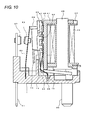
Fig. 10 is a cross-sectional view illustrating a state in which the case is removed from the structure ofFig. 1 when the contact is open; -
Fig. 11 is an enlarged perspective view of a contact switching unit ofFig. 3 ; -
Fig. 12 is a graph illustrating an attracting force curve of the electromagnet block ofFig. 4 and illustrating a change in force exerting on a movable contact piece; -
Fig. 13A is a perspective view illustrating a state before processing a fixed contact piece andFig. 13B is a perspective view illustrating a state after processing the fixed contact piece; -
Fig. 14 is an enlarged partial perspective view illustrating a portion of a base ofFig. 3 , in which a fixed contact piece is installed, when viewed from the bottom surface side; and -
Fig. 15 is a front view illustrating a fixed contact piece according to another embodiment. - Hereinafter, preferred embodiments of the present invention will be described with reference to the drawings. Note that in the description below, terms that refer to specific directions and positions (for example, terms including "upper", "lower", "side", and "end") are used if necessary. The purpose of using those terms is to help better understand the present invention referring to the drawings, but the technical scope of the present invention should not be limited by meanings of those terms. The description made hereinbelow represents just an essential example of the present invention and is not intended to limit the present invention, applications of the present invention, and uses of the present invention.
-
Figs. 1 to 5 illustrate an electromagnetic relay according to an embodiment of the present invention. Briefly, as for this electromagnetic relay, anelectromagnet block 2, acontact switching unit 3, and amovable iron piece 4 are installed on abase 1, and the whole structure is encased in acase 5. - The
base 1 is rectangular in a plan view and is formed by performing a molding process with a synthetic resin material as shown inFigs. 6A and 6B . In thebase 1, there are two installation areas including afirst installation portion 6 and asecond installation portion 7 arranged in a longitudinal direction. Hereafter, the longitudinal direction running along a longer side is referred to as X-axis, a lateral direction running along a shorter side is referred to as Y-axis, and a direction running along the height is referred to as Z-axis. - The
first installation portion 6 is an area reserved for installation of theelectromagnet block 2 to be described later and is configured in a manner that a supportingconcave portion 10 is formed in arecess 9 surrounded with afirst periphery wall 8 formed on an upper surface of thebase 1 and with asecond installation portion 7. In the bottom of therecess 9, a pair of coil terminal holes 11 that completely pass through the bottom of therecess 9 from the upper side to the lower side are formed at both sides of the supportingconcave portion 10 in the lateral direction of the base 1 (the direction of YY'), respectively. In a lower surface of thebase 1, concave sealing portions, each with four tapered side surfaces, are formed such that each concave sealing portion is formed in a surrounding area of a location where the coil terminal hole 11 is open. - A
guide portion 12 is formed near the supporting concave portion 10 (in the longitudinal direction of the base 1). Theguide portion 12 includes a pair ofguide walls 13 which are formed to correspond to the shorter-side direction (the direction of YY'), and aninsulation wall 14 that connects the pair ofguide walls 13. Guide grooves 15 each of which vertically extends are formed in opposing surfaces of theguide walls 13, respectively. Both sides of ayoke 41 to be described later are guided by both the guide grooves 15. Moreover, aconcave guide portion 16 is formed at a center portion of an area surrounded with theguide walls 13 and theinsulation wall 14. A to-be-guided portion 50 of ahinge spring 44 to be described later is located in theconcave guide portion 16. - The
second installation portion 7 is an area reserved for thecontact switching unit 3, and a plinth 17 having the same height as thefirst periphery wall 8 of thefirst installation portion 6 is formed in thesecond installation portion 7. In the plinth 17, a slit-like firstterminal hole 18 extending in the direction of YY' is formed. The firstterminal hole 18 passes through the bottom of thebase 1 only at two locations where communicatingportions 19 are formed, and a movable contact piece 52 to be described later is press-fitted into the firstterminal hole 18. Asecond periphery wall 20 is formed at three sides of the plinth 17 except for one side that is near the first installation portion. A part of thesecond periphery wall 20 which is disposed on the side of the X' direction side is relatively thick and has a pair of slit-like second terminal holes 21 which extend and are arranged in the direction of YY'. Each secondterminal hole 21 is formed by opening the bottom surface of the concave portion which is formed in the upper surface of thebase 1 while leaving a middle portion of the bottom surface of the concave portion. When fixedcontact pieces 51 to be described later are press-fitted into the respective second terminal holes 21 so as to be fixed, a lower edge of the press-fittedportion 53 comes in contact with the bottom surface so that positioning at insertion positions is achieved. Each of the second terminal holes 21 is located near the short side of thebase 1 in the X' direction, and a distance between the opening in the lower surface and the shorter side is small. Moreover, as illustrated inFig. 14 , a recess 1 a extending from the position of the opening of each secondterminal hole 21 to the short side of thebase 1 is formed in the lower surface of thebase 1. The bottom surface of the recess 1 a is tapered like a mountain, that is, the recess 1 a is deepest at the center thereof. - As illustrated in
Figs. 7 and8 , theelectromagnet block 2 is a structure formed by winding acoil 24 around aniron core 22 using aspool 23. - The
iron core 22 is a bar of an electromagnetic material. As for theiron core 22, a flange-likemagnetic pole portion 25 is formed at a lower end of theiron core 22 and theyoke 41 is fastened to an upper end of theiron core 22. - The
spool 23 is obtained by performing a molding process with a synthetic resin material, and includes acylindrical trunk 27 having a center hole 26 formed therein and flanges (an upper-end flange 28 and a lower-end flange 29) formed at an upper end and a lower end of thecylindrical trunk 27, respectively: - In an upper surface of the upper-
end flange 28, a relief groove 30 is formed and the center hole 26 is open. An end of theyoke 41 to be described later is disposed in the relief groove 30. The center hole 26 is also open in the lower-end flange 29 and theiron core 22 can be inserted into the center hole 26 from the lower-end flange 29. - Terminal attachment portions 31 are provided at both sides of the lower-
end flange 29, respectively and terminal holding holes 32 are formed there, respectively.Coil terminals 36 to be described later are press-fitted in and fixed to the terminal holding holes 32, respectively. Step portions 33 are formed on both sides of an end of the terminal attachment portion 31, respectively, and coil winding portions 39 of thecoil terminals 36 which are press-fitted in theterminal holding holes 32 to be fixed project over the step portions 33, respectively. Moreover, the lower-end flange 29 has a guide groove 34 that communicates with one of the step portions 33 via a way from thetrunk 27 to a side end surface thereof. An end of the coil 24 (a beginning end of turns of the coil 24) wound around thetrunk 27 is disposed in the guide groove 34, and thecoil 24 is wound around the coil winding portion 39 of thecoil terminal 36 which projects over the step portion 33. A pair ofguide protrusions 35 are provided in the bottom surface of the lower-end flange 29 at a predetermined interval. The guide protrusions 35 serve to position thespool 23, in other words, theelectromagnet block 2 with respect to thebase 1 by being put in the supportingconcave portions 10 of thebase 1. - The
coil terminal 36 is a plate-like body of an electrically conductive material, and its lower end portion is tapered to the bottom such that the width and thickness are gradually decreased toward the bottom. Thecoil terminal 36 has a press-fittedportion 37 which is expanded from one surface of the plate-like body through a press-working process at an upper end portion thereof, and a portion of thecoil terminal 36 on the upper side of the press-fittedportion 37 is formed as a wide width portion 38. The coil winding portion 39 projects from one end of the wide width portion 38. - The
coil 24 is wound around thetrunk 27 of thespool 23, and aninsulation sheet 40 is attached to the outer circumferential surface of thecoil 24. One end of thecoil 24 is arranged in the guide groove 34 of thespool 23, and thecoil 24 is then wound around thetrunk 27 of thespool 23. After that, both ends of thecoil 24 are wound around the coil winding portion 39 of thecoil terminal 36, and then soldered to be fixed. - The
yoke 41 is fastened to an end of theiron core 22.
Theyoke 41 is made of a magnetic material and has a bent body of a substantial L shape. An end of theyoke 41 is provided with an opening 41 a so that an end of theiron core 22 is inserted in the opening 41 a so as to be fastened to the end of theyoke 41. The other end of theyoke 41 is a wide width portion, and protruding portions 42 are provided at both sides of a lower end of the wide width portion, respectively. Themovable iron piece 4 to be described later is located between both the protruding portions 42, and one corner of the protruding portions 42 functions as a fulcrum on which themovable iron piece 4 is movably supported. In a middle portion of theyoke 41, two fastening projections 43 are formed on an outside surface of theyoke 41 and they are arranged on a vertical line. - A
hinge spring 44 is fastened to the middle portion of theyoke 41 by using the projections 43. However, the method of fixing thehinge spring 44 to theyoke 41 is not limited to the fastening, but a different method such as ultrasonic welding, resistance welding, laser welding, or the like may be used. - The
hinge spring 44 includes a joint portion 45 that comes in contact with the outside surface of the middle portion of theyoke 41. The joint portion 45 has through-holes 45a at two locations and the projections 43 of theyoke 41 are inserted into the through-holes 45 so as to be fastened. - The upper side of the joint portion 45 is an
elastic contact portion 46 which extends at a predetermined angle as if theelastic contact portion 46 gradually becomes farther from the outside surface of the middle portion of theyoke 41. Theelastic contact portion 46 is configured to be able to come in contact with a pressing force receiving portion of a card member 65 provided to themovable iron piece 4 to be described later. Theelastic contact portion 46 alleviates collision noise generated when themovable iron piece 4 returns to a default position. - The lower side of the joint portion 45 is an
elastic support portion 49 which includes afirst inclination portion 47 extending at a predetermined angle as if it gradually becomes farther from the outside surface of the middle portion of theyoke 41 and a second inclination portion 48 extending from thefirst inclination portion 47 at a predetermined angle as if it gradually becomes closer toyoke 41. The second inclination portion 48 of theelastic support portion 49 is in pressure-contact with themovable iron piece 4 to be described later so that themovable iron piece 4 is elastically, turnably supported on theelastic support portion 49. - The lower side of the
elastic support portion 49 serves as the to-be-guided portion 50 which extends downward in a vertical direction in a state in which themovable iron piece 4 is elastically supported on theelastic support portion 49. The to-be-guided portion 50 is arranged in theconcave guide portion 16 formed in thefirst installation portion 6 of thebase 1 and guided by theconcave guide portion 16 so that thehinge spring 44 is prevented from being mispositioned. - The
contact switching unit 3, as illustrated inFigs. 4 and5 , includes the fixedcontact pieces 51 and the movable contact piece 52, each of which is obtained by performing press working on an electrically conductive material such as copper. - The fixed
contact piece 51 is an example of the terminal member with the sealing structure according to the present invention, and includes a press-fittedportion 53, aterminal portion 54 extending downward from the press-fittedportion 53, and acontact piece portion 55 extending upward from the press-fittedportion 53. - The press-fitted
portion 53 is provided with expansion portions 56 that are expanded from one surface thereof by using the press working process. The press-fittedportion 53 can be press-fitted into the secondterminal hole 21 of thebase 1 by using the this expansion portions 56. - The
terminal portion 54 is formed by changing a flat panel of an almost rectangular shape connected to a narrow width portion 54b which is formed by arc-shaped notch portions 54a formed at both sides thereof as shown inFig. 13A into a plate shape shownFig. 13B by folding over both sides of the almost rectangular flat panel. That is, theterminal portion 54 is a plate-like body including a planar portion 54c connected to the press-fittedportion 53 and folded portions 54d that are folded over to overlap the planar portion 54c. The plate-like terminal portion 54 has a smaller width than the press-fittedportion 53 and is deviated from the centerline. Moreover, theterminal portion 54 has a thickness about two times that of thecontact piece portion 55 so that enough strength can be secured. Moreover, the notch portions 54a facilitate folding of the folded portions 54d. - In the middle portion of the
terminal portion 54, a predetermined gap extending in the longitudinal direction exists between the folded portions 54d so that a groove 54e is formed by the folded portions 54d and the planar portion 54c. Moreover, at leading end portions of the folded portions 54d and the planar portion 54c, opposite outside surfaces gradually become closer to their respective overlapping surfaces such that the plate thickness is decreased toward a leading edge. The leading end portions function as an insertion portion 54f. An upper end portion of each of the folded portions 54d has a cut-away portion 54i consisting of an inclined edge 54g and an L-shaped edge 54h, in which the inclined edge gradually slops toward the middle portion of the terminal portion with respect to the leading end portion and the L-shaped edge 54h is disposed near the groove 54e. Then, a lower edge of the press-fittedportion 53 comes in contact with the bottom of the secondterminal hole 21 of thebase 1 in a state in which theterminal portion 54 is press-fitted into thebase 1, so that theterminal portion 54 is not further press-inserted thereafter. As a result, as for theterminal portion 54, the portions extending from the lower surface of thebase 1 include the L-shaped edge 54h and part of the inclined edge 54g of the cut-away portion 54i. At a location where both the folded portions 54d face each other, a sealing agent reservoir 54j is formed by the surface of the planar portion 54c and the L-shaped edges 54h, so that the sealing agent is prevented from flowing to the leading end portion of theterminal portion 54. - The
contact piece portion 55 is formed on the opposite side of theterminal portion 54 and misaligned with theterminal portion 54. Since the terminal portion has an overlappingly folded structure, the contact piece portion is allowed to have such a small thickness that enables the contact piece portion to be elastically deformed. A middle portion of thecontact piece portion 55 is provided with a slit 55a and an upper end portion of thecontact piece portion 55 is provided with a through-hole in which the fixedcontact 57 is fastened. - The movable contact piece 52 includes a press-fitted portion 58 and a pair of
contact piece portions 59 extending upward from both sides of the press-fitted portion 58, respectively. At a center portion of the press-fitted portion 58 in the vertical direction, anexpansion portion 60 extending in the widthwise direction is formed like in the fixedcontact piece 51. Theexpansion portion 60 can be press-fitted into the firstterminal hole 18 of thebase 1. Moreover, a pair ofprojections 61 that project downward are respectively formed at both ends of a lower edge of the press-fitted portion 58. Thecontact piece portion 59 is bent at a location near the press-fitted portion 58 and has a through-hole 59a at an upper end portion thereof, and themovable contact 62 is fastened by the through-hole 59a. The movable contact piece 52 is arranged such that themovable contact 62 can move closer to and away from the fixedcontact 57 of the fixedcontact piece 51 which is press-fitted into the secondterminal hole 21 in a state in which the press-fitted portion 58 is press-fitted into the firstterminal hole 18 of thebase 1. - 1-4.
Movable iron piece 4
Themovable iron piece 4 is formed by performing press working on a plate of a magnetic material so that the plate becomes an L shape as shown inFigs. 7 and8 . An end portion of themovable iron piece 4 is a to-be-attracted portion 63 which is to be attracted to themagnetic pole portion 25 of theiron core 22. A leading end portion and a base portion of the to-be-attracted portion 63 has a small width, so that an interference between the protruding portions 42 formed in the lower end portion of theyoke 41 and theguide protrusion 35 formed in the bottom surface of thespool 23 can be avoided. The other end portion of themovable iron piece 4 is provided with an opening 64. Thehinge spring 44 passes through the opening 64, and comes in pressure-contact with a corner portion of the to-be-attracted portion 63. The other end portion of themovable iron piece 4 has a small width, and the card member 65 is integrally formed with an upper portion of themovable iron piece 4 which is disposed on the upper side of the opening 64. - The card member 65 is made of a synthetic resin material. On one surface of the card member 65 from which the upper end portion of the
movable iron piece 4 which is integrally formed with the card member 65 is exposed, first protrudingportions 66 are formed at both sides of the upper end portion of themovable iron piece 4, respectively and a second protrudingportion 67 is formed at an upper side of the first protrudingportions 66. When the to-be attracted portion 63 of themovable iron piece 4 is separated from themagnet pole portion 25 of theiron core 22, theelastic contact portion 46 of thehinge spring 44 collides with the second protrudingportion 67, and after which the first protrudingportion 66 comes into contact with theyoke 41. On the other surface of the card member 65, projection portions 68 extending in the vertical direction are formed at a predetermined interval in the widthwise direction. Pressingportions 69 which project more than the projection portions 68 are formed at upper ends of the projection portions 68, respectively so that thepressing portions 69 can press the upper ends of thecontact piece portion 59 of the movable contact piece 52. Ashield wall 70 which protrudes more than the other surface and extends downward is formed at a lower end portion of the card member 65. - The
case 5 has a box shape which is open at a lower end as shown inFig. 2 and is made of a synthetic resin material. Thecase 5 has a sealinghole 71 in a corner of an upper surface. After a fitting portion of thebase 1 and thecase 5 is sealed, the sealinghole 71 is closed by heat sealing. At an edge of the upper surface of thecase 5 on the opposite side of the sealinghole 71, slit-likeconcave portions 72 are formed at both side portions and a center portion, respectively. Arecess 73 that is recessed from the upper surface of thecase 5 is formed every between theconcave portions 72, and aprojection 74 is formed at a center portion of the surface of therecess 73. - An arc-extinguishing member 75 is attached to the
case 5 using theconcave portions 72 and therecess 73. - The arc-extinguishing member 75 includes a pair of
permanent magnets 76, arranged at a predetermined interval, for extinguishing the arc and ajoint member 77, made of a magnetic material, for magnetically connecting thesepermanent magnets 76. - The
permanent magnets 76 have an almost rectangular parallelepiped shape and are arranged such that opposite sides thereof may have different polarities in a state in which thepermanent magnets 76 are attached to the opposite insidewalls 78 of thejoint member 77. However, the polarities of the opposing surfaces may be set such that the direction of force exerting on the arc current which changes according to the direction of the current flowing at a contact point is directed toward amiddle wall 79 of thejoint member 77 to be described later. - The
joint member 77 is formed by performing press working on a plate of a magnetic material such that both ends are bent so as to face each other. Thepermanent magnets 76 are attracted and fixed to the inside surfaces of the opposingwalls 78, respectively. In themiddle wall 79 of thejoint member 77, both side portions of themiddle wall 79 are cut away at different locations which are nearer opposite ends, respectively, so that middle protruding portions 80 are formed between the opposingwalls 78. Each of the middle protruding portions 80 serves to shorten a magnetic path by being located in the middle portion between both the opposingwalls 78 and protruding between both contact switching positions. That is, in a magnetic circuit, a closed loop is formed such that the magnetic flux generated from each of thepermanent magnets 76 passes themiddle wall 79 and each of the opposingwalls 78 via the middle protruding portions 80, and returns to thepermanent magnets 76. - As described above, the arc-extinguishing member 75 is provided with not only the pair of
permanent magnets 76 but also thejoint member 77 to magnetically connect thepermanent magnets 76. Therefore, the magnetic circuit is formed, and as a result, it becomes difficult for the magnetic flux to leak. Moreover, since the middle protruding portions 80 are provided, the magnetic path can be shortened. Therefore, magnetic efficiency can be improved. Accordingly, even if an arc occurs at the time when the contact is opened or closed, this arc elongates to the sides according to the Fleming's left hand rule, and as a result, the arc is extinguished in a short time. - Next, a method of assembling a magnetic relay having the structure described above is described.
- The
coil 24 is wound around thetrunk 27 of thespool 23, and thecoil terminal 36 is press-fitted and fixed to the lower-end flange 29. Both ends of thecoil 24 are wound around the coil winding portion 39 and soldered. Moreover, theiron core 22 is inserted to pass through the center hole 26 of thespool 23 from the lower end of thespool 23, and theyoke 41 to which thehinge spring 44 is attached beforehand is fastened to the a portion of theiron core 22 which is exposed from the upper end of the spool. As a result, theelectromagnet block 2 assembly is completed. - In the
finished electromagnet block 2, themovable iron piece 4 is supported in a turnable manner on the lower end of theyoke 41 by using thehinge spring 44. Under this condition, the first protrudingportion 66 of the card member 65 which is integrally formed with themovable iron piece 4 can come into contact with theyoke 41, and theelastic contact portion 46 of thehinge spring 44 can move closer to and away from the second protrudingportion 67 of the card member 65. Next, theelectromagnet block 2 to which themovable iron piece 4 is attached, and thecontact switching unit 3 is installed in thebase 1. - When installing the
electromagnet block 2, thecoil terminal 36 is press-fitted into the coil terminal hole 11 of thebase 1, and both side portions of theyoke 41 are inserted into the guide grooves 15 of theguide wall 13. In the installed state, theguide protrusion 35 is located in the supportingconcave portion 10, and theelectromagnet block 2 is positioned on one side thereof in the direction of YY'. Moreover, the lower end surface of the protruding portion 42 of theyoke 41 and the bottom surface of the terminal attachment portion 31 come in contact with the bottom surface of therecesses 9 of thebase 1 respectively. As a result, a gap is formed between the bottom surface of therecess 9 of thebase 1 and the bottom surface of the lower-end flange 29 of thespool 23, and themovable iron piece 4 is turnable in the gap. Theshield wall 70 of the card member 65 which is integrally formed with themovable iron piece 4 is arranged over theinsulation wall 14 of thebase 1. At this time, the insulation performance between theelectromagnet block 2 and thecontact switching unit 3 is sufficiently secured due to the presence of theguide wall 13 andinsulation wall 14 of thebase 1, and an upper portion of the card member 65 and theshield wall 70. - When installing the
contact switching unit 3, the press-fitted portion 58 of the movable contact piece 52 is press-fitted into the firstterminal hole 18 of thebase 1. When installing the movable contact piece 52, since theprojection 61 is located in the communicatingportion 19, the installation state of the movable contact piece 52 can be confirmed by viewing the bottom surface of thebase 1. Moreover, thepressing portion 69 of the card member 65 which has been installed beforehand comes in pressure-contact with the upper end portion of the movable contact piece 52, and themovable iron piece 4 is positioned at the default position at which the to-be-attracted portion 63 is separated from themagnetic pole portion 25 of theiron core 22 due to the elastic force of the movable contact piece 52. - Moreover, the
terminal portion 54 of the fixedcontact piece 51 is inserted into the secondterminal hole 21 of thebase 1, and the press-fittedportion 53 is then press-fitted so as to be fixed. Under this condition, the lower edge of the press-fittedportion 53 comes in contact with the partially left bottom surface of thesecond contact hole 21, so that the dimension of a protruding portion of theterminal portion 54 which protrudes from thebase 1 becomes a pre-set value. Moreover, the sealing agent reservoir 54j composed of a part of the inclined edge 54g and the L-shaped edge 54h which is connected to the inclined edge 54g is exposed from the lower surface of thebase 1 due to the cut-away portions 54i formed in theterminal portion 54. As a result, even in a case in which the position of the opening of the secondterminal hole 21 in the bottom surface of thebase 1 is near the short side of thebase 1, and thus a sufficient space cannot be secured, the sealing agent can be injected into the secondterminal hole 21 via the sealing agent reservoir 54j. Moreover, the fixedcontact piece 51 faces the movable contact piece 52 with a prescribed distance therebetween, and themovable contact 62 can move closer to or away from the fixedcontact 57. - Moreover, the arc-extinguishing member 75 is installed in the
case 5. When installing the arc-extinguishing member 75, in the state in which thepermanent magnets 76 are attached to the opposingwalls 78 of thejoint member 77, the opposingwalls 78 of thejoint member 77, thepermanent magnets 76, and the middle protruding portion 80 are inserted into theconcave portions 72, respectively formed in thecase 5. - Subsequently, the
base 1 is encased in thecase 5 in which the arc-extinguishing member 75 has been installed beforehand, and the fitting portion and then each of the terminal holes are sealed. In this case, in the secondterminal hole 21 from which theterminal portion 54 of the fixedcontact piece 51 protrudes, the sealing agent may be supplied to the sealing agent reservoir 54j as described above. The sealing agent supplied to the sealing agent reservoir 54j flows over a short distance along the inclined edge 54g so as to enter the secondterminal hole 21, so that the sealing agent seals up a gap between the secondterminal hole 21 and theterminal portion 54. Thus, since the sealing agent is injected from the sealing agent reservoir 54j exposed from thebase 1, the secondterminal hole 21 can be reliability filled with the sealing agent. Moreover, since the flow of the surplus sealing agent is blocked by a structure formed by the L-shaped edge 54h of the sealing agent reservoir 54j, the surplus sealing agent does not spread to a portion of theterminal portion 54 which protrudes from the lower surface of thebase 1. - Next, the operation of the magnetic relay having the above-described structure will be described.
- Under a condition in which the
coil 24 is not energized and theelectromagnet block 2 is demagnetized, themovable iron piece 4 is located at the default position at which the to-be-attracted portion 63 is separated from themagnetic pole portion 25 of theiron core 22 because themovable iron piece 4 causes the to-be-attracted portion 63 to turn about the fulcrum supported by theyoke 41 by using the elastic force of the movable contact piece 52. Therefore, themovable contact 62 maintains the open state in which themovable contact 62 is separated from the fixedcontact 57. - When the
coil 24 is energized and theelectromagnet block 2 is excited, the to-be-attracted portion 63 of themovable iron piece 4 is attracted to themagnetic pole portion 25 of theiron core 22 and turns against the biasing force of the movable contact piece 52 as shown inFig. 9 . Such an operation allows the movable contact piece 52 to be elastically deformed and allows themovable contact 62 to be in contact with the fixedcontact 57 of the fixedcontact piece 51. - When energizing the
coil 24 is stopped and theelectromagnet block 2 is demagnetized, themovable iron piece 4 is not attracted by theiron core 22 anymore so that themovable iron piece 4 turns due to the elastomeric force of the movable contact piece 52. At this time, the second protrudingportion 67 formed on the card member 65 of themovable iron piece 4 collides with theelastic contact portion 46 of thehinge spring 44. The second protrudingportion 67 is made of a synthetic resin so that theelastic contact portion 46 is elastically deformed. However, a contact state of the second protrudingportion 67 and theelastic contact portion 46 is obtained within a short time after themovable iron piece 4 starts turning. Accordingly, nearly no collision noise is generated. Then, as themovable iron piece 4 turns further, theelastic contact portion 46 is elastically deformed and the first protrudingportion 66 made of a synthetic resin comes into contact with the middle portion of theyoke 41. Accordingly, the turning speed of themovable iron piece 4 is reduced, and this also serves to sufficiently suppress generation of the collision noise. In this way, themovable iron piece 4 smoothly returns to the default position without generating the collision noise and themovable contact 62 is separated from the fixedcontact 57 and is positioned at an open position. - Incidentally, at the time when the contact is opened, an arc might occur between contact points. In this case, since the arc-extinguishing member 75 is arranged around a contact switching area, the generated arc is promptly extinguished.
- That is, the magnetic flux generated from the N pole of each of the
permanent magnets 76 runs in a magnetic circuit in which the magnetic flux passes themiddle wall 79 via the middle protruding portions 80 of thejoint member 77, and returns to the S pole of each of thepermanent magnet 76 from the opposingwalls 78. Each magnetic circuit forms a closed-loop so that nearly zero magnetic flux leaks to surroundings. Moreover, because of the presence of the middle protruding portion 80, the magnetism can be effectively exerted on the arc generated at the contact switching position, in other words, between the contacts points. As a result, the force is exerted on the generated arc in a direction orthogonal to the direction in which the contact is opened according to the Fleming's left hand rule, so that this arc is extended over a long distance. Therefore, the arc is rapidly extinguished. - Here, since both the fixed
contact pieces 51 are opened or closed by using the movable contact piece 52, the arc current flows in the direction shown inFig. 11 at the time when the contacts are opened. Accordingly, the magnetic poles of thepermanent magnets 76 are set in a manner that the magnetic poles of the opposing surfaces are different so that the direction of the magnetic flux which enables the arc to be deformed toward the middle wall of thejoint member 77 can be obtained. That is, the arc can be more certainly extinguished because the arc is deformed toward the middle wall of thejoint member 77. Therefore, if thecontact switching unit 3 is differently structured from the above manner, the magnetic poles of thepermanent magnets 76 may be set in a manner corresponding to such a structure. - Moreover, an operating voltage of the
electromagnet block 2 can be adjusted as follows.
That is, the operating voltage of theelectromagnet block 2 can be controlled by changing the inclination angle of theelastic contact portion 46 of thehinge spring 44. In greater detail, if the inclination angle of theelastic contact portion 46 with respect to theyoke 41 is increased, the position of an operating point can be changed in accordance with a change in the force (attracting force curve) that exerts on the to-be-attracted portion 63 of themovable iron piece 4 due to the magnetic field generated from themagnetic pole portion 25 of theiron core 22 as shown in the graph ofFig. 12 . That is, the force needed for a period from the opening of the contacts to the timing at which theelastic contact portion 46 comes into contact with the first protrudingportion 66 can be reduced by increasing the inclination angle of theelastic contact portion 46. Accordingly, the operating voltage of theelectromagnet block 2 can be controlled such that the attracting force curve can change in a narrower range than that ofFig. 12 . - The present invention is not limited to the structures described in the embodiment, and can be modified in various ways.
- For example, although the sealing agent reservoir 54j is configured by the inclined edge 54g and the L-shaped edge 54h of the folded portions 54d in the above-described embodiment, the L-shaped edge 54h can be changed to a V-shaped edge 54k as shown in
Fig. 15A so that the path that guides the sealing agent to the groove 54e can be increased. In this case, a problem that the sealing agent flows to positions other than the sealing position (mainly the second terminal hole 21) can be more adequately inhibited. - Moreover, the cut-away portion 54i can be formed to be broader in a corner portion of the L-shaped edge 54h or the V-shaped edge 54k. According to this structure, an event that the sealing agent flows to positions other than the sealing position can be much more adequately prevented.
- Moreover, even though the
terminal portion 54 is formed such that the folded portions 54d are folded from both sides in the above-described embodiment, the folded portions 54d are not necessarily folded from both sides. That is, as illustrated inFig. 15B , the terminal portion may have a structure having only one folded portion which is folded over from one side. - Moreover, even though the above-described embodiment discloses an example in which the sealing structure of a terminal member according to the present invention is adopted in an electromagnetic relay, the sealing structure of a terminal member according to the present invention can be adopted not only in the electromagnetic relay but also in other electronic devices, for example, a switch as long as the electronic devices include an electric switch.
- There has thus been shown and described a novel sealing structure of a terminal member using the same which fulfills all the objects and advantages sought therefor. Many changes, modifications, variations and other uses and applications of the subject invention will, however, become apparent to those skilled in the art after considering this specification and the accompanying drawings which disclose the preferred embodiments thereof. All such changes, modifications, variations and other uses and applications which do not depart from the spirit and scope of the invention are deemed to be covered by the invention, which is to be limited only by the claims which follow.
- Although the invention has been described in detail for the purpose of illustration based on what is currently considered to be the most practical and preferred embodiments, it is to be understood that such detail is solely for that purpose and that the invention is not limited to the disclosed embodiments, but, on the contrary, is intended to cover modifications and equivalent arrangements that are within the spirit and scope of the appended claims. For example, it is to be understood that the present invention contemplates that, to the extent possible, one or more features of any embodiment can be combined with one or more features of any other embodiment.
Claims (10)
- A sealing structure of a terminal member to be press-fitted in a terminal hole of a base, wherein the terminal member includes a press-fitted portion to be press-fitted in the terminal hole and a terminal portion extending from the press-fitted portion and for protruding from the base, wherein the terminal portion is configured by a folded plate-like body such that folded portions overlap a planar portion, at least one of the folded portions having a cut-away portion for extending from the base, at an edge near the press-fitted portion, and configured for a sealing agent to be injected into the terminal hole via the at least one cut-away portion.
- The sealing structure of a terminal member according to claim 1, wherein
the terminal portion has a structure in which both sides of the plate-like body are folded such that the folded portions overlap the planar portion, and
the folded portions have respective cut-away portions at opposing sides thereof, respectively. - The sealing structure of a terminal member according to claim 1, wherein each cut-away portion has an inclined edge which unites the portion for extending from the base to the inside of the terminal hole.
- The sealing structure of a terminal member according to claim 3, wherein the at least one cut-away portion is formed by cutting away opposing portions of both the folded portions in the portion extending from the base so that the cut-away portions and the planar portion forming a sealing agent reservoir.
- The sealing structure of a terminal member according to claim 4, wherein among portions of the at least one cut-away portion, portions that form the sealing agent reservoir are partially broader than the other portions.
- The sealing structure of a terminal member according to claim 1, wherein the terminal member further includes a contact piece portion for protruding from a side of the base opposite to a side from which the terminal portion protrudes, the contact piece portion having a contact at a leading end thereof and being elastically deformable.
- An electromagnetic relay comprising:a fixed contact piece having the sealing structure according to claim 1.
- A method of manufacturing an electromagnetic relay, the method comprising:punching out a plate-like body;folding both sides of the punched-out plate-like body to form a terminal portion in which folded portions overlap a planar portion;press-fitting the terminal portion into a terminal hole from a first surface of a base so that the terminal portion protrudes from a second surface of the base; andinjecting a sealing agent into the terminal hole from the second surface of the base, whereinin the punching-out of the plate-like body, the plate-like body is punched out such that a cut-away portion, connected from the terminal hole of the base to the outside at the time when the terminal portion is press-fitted into the terminal hole of the base in the press-fitting of the terminal portion, is formed in the folded portion.
- The method of manufacturing an electromagnet relay according to claim 8, wherein
in the punching-out of the plate-like body, the plate-like body is punched out such that a cut-away portion, having an inclined edge that unites the inside of the terminal hole of the base with the portion extending from the base when the terminal portion is press-fitted into the terminal hole of the base in the press-fitting of the terminal portion, is formed in the folded portions. - The method of manufacturing an electromagnet relay according to claim 9, wherein, in the punching-out of the plate-like body, the plate-like body is punched out such that opposing portions of both the folded portions are cut away so that a sealing agent reservoir defined by the cut-away portions of the folded portions and the planar portion is formed in the portion extending from the base when the terminal portion is press-fitted into the terminal hole of the base in the press-fitting of the terminal portion.
Applications Claiming Priority (1)
| Application Number | Priority Date | Filing Date | Title |
|---|---|---|---|
| JP2011202138A JP5741338B2 (en) | 2011-09-15 | 2011-09-15 | Terminal member seal structure and electromagnetic relay |
Publications (3)
| Publication Number | Publication Date |
|---|---|
| EP2571040A2 true EP2571040A2 (en) | 2013-03-20 |
| EP2571040A3 EP2571040A3 (en) | 2014-12-24 |
| EP2571040B1 EP2571040B1 (en) | 2015-12-09 |
Family
ID=46650311
Family Applications (1)
| Application Number | Title | Priority Date | Filing Date |
|---|---|---|---|
| EP12005272.5A Active EP2571040B1 (en) | 2011-09-15 | 2012-07-18 | Sealing structure of terminal member, electromagnetic relay, and method of manufacturing the same |
Country Status (4)
| Country | Link |
|---|---|
| US (1) | US8558647B2 (en) |
| EP (1) | EP2571040B1 (en) |
| JP (1) | JP5741338B2 (en) |
| CN (1) | CN103151225B (en) |
Cited By (1)
| Publication number | Priority date | Publication date | Assignee | Title |
|---|---|---|---|---|
| FR3006101A1 (en) * | 2013-05-23 | 2014-11-28 | Socomec Sa | ELECTRICAL CUTTING DEVICE, IN PARTICULAR FOR CONTINUOUS CURRENT EQUIPPED WITH A MAGNETIC MODULE FOR BLOWING THE ELECTRIC ARC |
Families Citing this family (12)
| Publication number | Priority date | Publication date | Assignee | Title |
|---|---|---|---|---|
| JP6117661B2 (en) * | 2013-09-19 | 2017-04-19 | 日立オートモティブシステムズ株式会社 | Electronic control unit |
| JP6291931B2 (en) * | 2014-03-14 | 2018-03-14 | オムロン株式会社 | Electronic device seal structure and electromagnetic relay using the electronic device seal structure |
| DE102015208134A1 (en) * | 2015-01-30 | 2016-08-04 | Te Connectivity Germany Gmbh | Arrangement for an electrical switching device |
| JP6447919B2 (en) * | 2015-04-07 | 2019-01-09 | パナソニックIpマネジメント株式会社 | Electromagnetic relay |
| KR101943363B1 (en) * | 2015-04-13 | 2019-04-17 | 엘에스산전 주식회사 | Magnetic Switch |
| JP6981732B2 (en) * | 2015-09-28 | 2021-12-17 | 富士通コンポーネント株式会社 | Electromagnetic relay |
| JP2017201593A (en) * | 2016-05-02 | 2017-11-09 | 富士通コンポーネント株式会社 | Electromagnetic relay |
| JP6787182B2 (en) * | 2017-02-28 | 2020-11-18 | オムロン株式会社 | Seal structure of electronic device, electronic device with seal structure, and manufacturing method of electronic device |
| JP1592947S (en) * | 2017-05-16 | 2017-12-11 | ||
| JP2021144919A (en) * | 2020-03-13 | 2021-09-24 | オムロン株式会社 | Electromagnetic relay and electronic circuit |
| CN112498750B (en) * | 2020-11-12 | 2022-05-27 | 上海宇航系统工程研究所 | Low impact space butt joint electromagnetic sealing device |
| USD994618S1 (en) * | 2021-05-13 | 2023-08-08 | Song Chuan Precision Co., Ltd. | Relay |
Citations (1)
| Publication number | Priority date | Publication date | Assignee | Title |
|---|---|---|---|---|
| JP3213978B2 (en) | 1991-09-18 | 2001-10-02 | 富士通株式会社 | Hermetic electromagnetic relay |
Family Cites Families (32)
| Publication number | Priority date | Publication date | Assignee | Title |
|---|---|---|---|---|
| US4390231A (en) * | 1978-06-28 | 1983-06-28 | General Motors Corporation | Blade terminal with protected latch tangs |
| JPS6356546U (en) * | 1986-09-30 | 1988-04-15 | ||
| JPH0755791Y2 (en) * | 1989-12-20 | 1995-12-20 | 株式会社高見澤電機製作所 | Relay terminal sealing structure |
| JPH03213978A (en) | 1990-01-19 | 1991-09-19 | Matsushita Refrig Co Ltd | Condensing unit |
| US5237742A (en) * | 1991-03-29 | 1993-08-24 | Elco Corporation | Method of producing electrical contact socket |
| DE69219524T2 (en) * | 1991-06-18 | 1997-08-14 | Fujitsu Ltd | Microminiature relay and method for its manufacture |
| JPH05274984A (en) * | 1992-03-27 | 1993-10-22 | Omron Corp | Electromagnetic relay |
| US5389905A (en) * | 1992-04-22 | 1995-02-14 | Matsushita Electric Works, Ltd. | Damper, electromagnet assembly employing the damper, and relay employing the electromagnet assemblies |
| US5359305A (en) * | 1992-06-15 | 1994-10-25 | Matsushita Electric Works, Ltd. | Electromagnetic relay |
| US5289144A (en) * | 1992-08-21 | 1994-02-22 | Potter & Brumfield, Inc. | Electromagnetic relay and method for assembling the same |
| JP2588956Y2 (en) * | 1993-04-14 | 1999-01-20 | ナイルス部品株式会社 | Electromagnetic relay |
| ATE217441T1 (en) * | 1995-10-09 | 2002-05-15 | Tyco Electronics Logistics Ag | ELECTROMAGNETIC RELAY AND METHOD FOR THE PRODUCTION THEREOF |
| DE19537612C1 (en) * | 1995-10-09 | 1997-01-09 | Siemens Ag | Electromagnetic relay and process for its manufacture |
| DE59700564D1 (en) * | 1996-05-07 | 1999-11-18 | Siemens Ag | ELECTROMAGNETIC RELAY |
| CN1107332C (en) * | 1996-05-27 | 2003-04-30 | 欧姆龙株式会社 | Electromagnetic relay |
| JP2904143B2 (en) * | 1996-08-26 | 1999-06-14 | 日本電気株式会社 | Electromagnetic relay |
| US5781089A (en) * | 1996-11-21 | 1998-07-14 | Siemens Electromechanical Components, Inc. | Electromagnetic relay |
| JP3849197B2 (en) * | 1997-02-06 | 2006-11-22 | 松下電工株式会社 | relay |
| KR100404770B1 (en) * | 1999-03-05 | 2003-11-07 | 오므론 가부시키가이샤 | Electromagnetic relay |
| US6771154B1 (en) * | 1999-11-12 | 2004-08-03 | Taiko Device, Ltd. | Electromagnetic relay |
| US6261123B1 (en) * | 2000-03-20 | 2001-07-17 | Delphi Technologies, Inc. | Battery pack manual disconnect |
| DE10209810B4 (en) * | 2001-03-09 | 2006-11-16 | Omron Corporation | relay |
| JP3898021B2 (en) * | 2001-10-05 | 2007-03-28 | 株式会社タイコーデバイス | Electromagnetic relay |
| JP2004063350A (en) * | 2002-07-30 | 2004-02-26 | Matsushita Electric Works Ltd | Terminal structure |
| JP4168733B2 (en) * | 2002-11-12 | 2008-10-22 | オムロン株式会社 | Electromagnetic relay |
| JP4111092B2 (en) * | 2003-07-28 | 2008-07-02 | 松下電工株式会社 | Terminal structure |
| JP4321256B2 (en) * | 2003-12-22 | 2009-08-26 | オムロン株式会社 | Electromagnetic relay |
| JP4471859B2 (en) * | 2005-01-31 | 2010-06-02 | 富士通コンポーネント株式会社 | Electromagnetic relay |
| JP4534915B2 (en) * | 2005-09-01 | 2010-09-01 | オムロン株式会社 | Electromagnetic relay |
| JP4810937B2 (en) * | 2005-09-06 | 2011-11-09 | オムロン株式会社 | Switchgear |
| US20070084633A1 (en) * | 2005-09-21 | 2007-04-19 | Tyco Electronic Corporation | Electromagnetic relay with noise reducing sealant |
| JP5004244B2 (en) * | 2008-05-30 | 2012-08-22 | Necトーキン株式会社 | Electromagnetic relay |
-
2011
- 2011-09-15 JP JP2011202138A patent/JP5741338B2/en active Active
-
2012
- 2012-07-12 US US13/548,131 patent/US8558647B2/en active Active
- 2012-07-18 EP EP12005272.5A patent/EP2571040B1/en active Active
- 2012-07-20 CN CN201210254411.4A patent/CN103151225B/en active Active
Patent Citations (1)
| Publication number | Priority date | Publication date | Assignee | Title |
|---|---|---|---|---|
| JP3213978B2 (en) | 1991-09-18 | 2001-10-02 | 富士通株式会社 | Hermetic electromagnetic relay |
Cited By (1)
| Publication number | Priority date | Publication date | Assignee | Title |
|---|---|---|---|---|
| FR3006101A1 (en) * | 2013-05-23 | 2014-11-28 | Socomec Sa | ELECTRICAL CUTTING DEVICE, IN PARTICULAR FOR CONTINUOUS CURRENT EQUIPPED WITH A MAGNETIC MODULE FOR BLOWING THE ELECTRIC ARC |
Also Published As
| Publication number | Publication date |
|---|---|
| CN103151225B (en) | 2015-12-16 |
| US8558647B2 (en) | 2013-10-15 |
| JP2013065412A (en) | 2013-04-11 |
| EP2571040B1 (en) | 2015-12-09 |
| CN103151225A (en) | 2013-06-12 |
| JP5741338B2 (en) | 2015-07-01 |
| EP2571040A3 (en) | 2014-12-24 |
| US20130069744A1 (en) | 2013-03-21 |
Similar Documents
| Publication | Publication Date | Title |
|---|---|---|
| EP2571040B1 (en) | Sealing structure of terminal member, electromagnetic relay, and method of manufacturing the same | |
| US8823474B2 (en) | Contact switching mechanism and electromagnetic relay | |
| KR101436268B1 (en) | Electromagnetic relay | |
| KR101436269B1 (en) | Electromagnetic relay | |
| KR101435349B1 (en) | Electromagnetic relay | |
| EP2650899B1 (en) | Electromagnetic relay | |
| KR101175023B1 (en) | Contact switching structure and electromagnetic relay | |
| US9437382B2 (en) | Electromagnet device and electromagnetic relay using the same | |
| KR20220128942A (en) | Electromagnetic relay | |
| WO2018159061A1 (en) | Seal structure of electronic device, and electronic device provided with seal structure | |
| WO2018159065A1 (en) | Seal structure of electronic device, electronic device provided with seal structure, and manufacturing method of electronic device | |
| CN115910691A (en) | Electromagnetic relay | |
| JP2021061169A (en) | Electromagnetic relay | |
| JPH10208603A (en) | Electromagnetic relay |
Legal Events
| Date | Code | Title | Description |
|---|---|---|---|
| PUAI | Public reference made under article 153(3) epc to a published international application that has entered the european phase |
Free format text: ORIGINAL CODE: 0009012 |
|
| AK | Designated contracting states |
Kind code of ref document: A2 Designated state(s): AL AT BE BG CH CY CZ DE DK EE ES FI FR GB GR HR HU IE IS IT LI LT LU LV MC MK MT NL NO PL PT RO RS SE SI SK SM TR |
|
| AX | Request for extension of the european patent |
Extension state: BA ME |
|
| PUAL | Search report despatched |
Free format text: ORIGINAL CODE: 0009013 |
|
| AK | Designated contracting states |
Kind code of ref document: A3 Designated state(s): AL AT BE BG CH CY CZ DE DK EE ES FI FR GB GR HR HU IE IS IT LI LT LU LV MC MK MT NL NO PL PT RO RS SE SI SK SM TR |
|
| AX | Request for extension of the european patent |
Extension state: BA ME |
|
| RIC1 | Information provided on ipc code assigned before grant |
Ipc: H01H 50/02 20060101AFI20141117BHEP Ipc: H01H 50/14 20060101ALI20141117BHEP Ipc: H01R 12/00 20060101ALI20141117BHEP Ipc: H01H 11/00 20060101ALI20141117BHEP Ipc: H01H 9/44 20060101ALI20141117BHEP |
|
| 17P | Request for examination filed |
Effective date: 20150420 |
|
| RBV | Designated contracting states (corrected) |
Designated state(s): AL AT BE BG CH CY CZ DE DK EE ES FI FR GB GR HR HU IE IS IT LI LT LU LV MC MK MT NL NO PL PT RO RS SE SI SK SM TR |
|
| GRAP | Despatch of communication of intention to grant a patent |
Free format text: ORIGINAL CODE: EPIDOSNIGR1 |
|
| INTG | Intention to grant announced |
Effective date: 20150715 |
|
| GRAS | Grant fee paid |
Free format text: ORIGINAL CODE: EPIDOSNIGR3 |
|
| GRAA | (expected) grant |
Free format text: ORIGINAL CODE: 0009210 |
|
| AK | Designated contracting states |
Kind code of ref document: B1 Designated state(s): AL AT BE BG CH CY CZ DE DK EE ES FI FR GB GR HR HU IE IS IT LI LT LU LV MC MK MT NL NO PL PT RO RS SE SI SK SM TR |
|
| REG | Reference to a national code |
Ref country code: GB Ref legal event code: FG4D |
|
| REG | Reference to a national code |
Ref country code: AT Ref legal event code: REF Ref document number: 764891 Country of ref document: AT Kind code of ref document: T Effective date: 20151215 Ref country code: CH Ref legal event code: EP |
|
| REG | Reference to a national code |
Ref country code: IE Ref legal event code: FG4D |
|
| REG | Reference to a national code |
Ref country code: DE Ref legal event code: R096 Ref document number: 602012012810 Country of ref document: DE |
|
| REG | Reference to a national code |
Ref country code: LT Ref legal event code: MG4D |
|
| REG | Reference to a national code |
Ref country code: NL Ref legal event code: MP Effective date: 20151209 |
|
| PG25 | Lapsed in a contracting state [announced via postgrant information from national office to epo] |
Ref country code: ES Free format text: LAPSE BECAUSE OF FAILURE TO SUBMIT A TRANSLATION OF THE DESCRIPTION OR TO PAY THE FEE WITHIN THE PRESCRIBED TIME-LIMIT Effective date: 20151209 Ref country code: NO Free format text: LAPSE BECAUSE OF FAILURE TO SUBMIT A TRANSLATION OF THE DESCRIPTION OR TO PAY THE FEE WITHIN THE PRESCRIBED TIME-LIMIT Effective date: 20160309 Ref country code: LT Free format text: LAPSE BECAUSE OF FAILURE TO SUBMIT A TRANSLATION OF THE DESCRIPTION OR TO PAY THE FEE WITHIN THE PRESCRIBED TIME-LIMIT Effective date: 20151209 |
|
| REG | Reference to a national code |
Ref country code: AT Ref legal event code: MK05 Ref document number: 764891 Country of ref document: AT Kind code of ref document: T Effective date: 20151209 |
|
| PG25 | Lapsed in a contracting state [announced via postgrant information from national office to epo] |
Ref country code: FI Free format text: LAPSE BECAUSE OF FAILURE TO SUBMIT A TRANSLATION OF THE DESCRIPTION OR TO PAY THE FEE WITHIN THE PRESCRIBED TIME-LIMIT Effective date: 20151209 Ref country code: GR Free format text: LAPSE BECAUSE OF FAILURE TO SUBMIT A TRANSLATION OF THE DESCRIPTION OR TO PAY THE FEE WITHIN THE PRESCRIBED TIME-LIMIT Effective date: 20160310 Ref country code: SE Free format text: LAPSE BECAUSE OF FAILURE TO SUBMIT A TRANSLATION OF THE DESCRIPTION OR TO PAY THE FEE WITHIN THE PRESCRIBED TIME-LIMIT Effective date: 20151209 Ref country code: RS Free format text: LAPSE BECAUSE OF FAILURE TO SUBMIT A TRANSLATION OF THE DESCRIPTION OR TO PAY THE FEE WITHIN THE PRESCRIBED TIME-LIMIT Effective date: 20151209 Ref country code: NL Free format text: LAPSE BECAUSE OF FAILURE TO SUBMIT A TRANSLATION OF THE DESCRIPTION OR TO PAY THE FEE WITHIN THE PRESCRIBED TIME-LIMIT Effective date: 20151209 Ref country code: LV Free format text: LAPSE BECAUSE OF FAILURE TO SUBMIT A TRANSLATION OF THE DESCRIPTION OR TO PAY THE FEE WITHIN THE PRESCRIBED TIME-LIMIT Effective date: 20151209 |
|
| PG25 | Lapsed in a contracting state [announced via postgrant information from national office to epo] |
Ref country code: IS Free format text: LAPSE BECAUSE OF FAILURE TO SUBMIT A TRANSLATION OF THE DESCRIPTION OR TO PAY THE FEE WITHIN THE PRESCRIBED TIME-LIMIT Effective date: 20151209 |
|
| REG | Reference to a national code |
Ref country code: FR Ref legal event code: PLFP Year of fee payment: 5 |
|
| PG25 | Lapsed in a contracting state [announced via postgrant information from national office to epo] |
Ref country code: CZ Free format text: LAPSE BECAUSE OF FAILURE TO SUBMIT A TRANSLATION OF THE DESCRIPTION OR TO PAY THE FEE WITHIN THE PRESCRIBED TIME-LIMIT Effective date: 20151209 |
|
| PG25 | Lapsed in a contracting state [announced via postgrant information from national office to epo] |
Ref country code: SM Free format text: LAPSE BECAUSE OF FAILURE TO SUBMIT A TRANSLATION OF THE DESCRIPTION OR TO PAY THE FEE WITHIN THE PRESCRIBED TIME-LIMIT Effective date: 20151209 Ref country code: RO Free format text: LAPSE BECAUSE OF FAILURE TO SUBMIT A TRANSLATION OF THE DESCRIPTION OR TO PAY THE FEE WITHIN THE PRESCRIBED TIME-LIMIT Effective date: 20151209 Ref country code: PT Free format text: LAPSE BECAUSE OF FAILURE TO SUBMIT A TRANSLATION OF THE DESCRIPTION OR TO PAY THE FEE WITHIN THE PRESCRIBED TIME-LIMIT Effective date: 20160411 Ref country code: EE Free format text: LAPSE BECAUSE OF FAILURE TO SUBMIT A TRANSLATION OF THE DESCRIPTION OR TO PAY THE FEE WITHIN THE PRESCRIBED TIME-LIMIT Effective date: 20151209 Ref country code: AT Free format text: LAPSE BECAUSE OF FAILURE TO SUBMIT A TRANSLATION OF THE DESCRIPTION OR TO PAY THE FEE WITHIN THE PRESCRIBED TIME-LIMIT Effective date: 20151209 Ref country code: IS Free format text: LAPSE BECAUSE OF FAILURE TO SUBMIT A TRANSLATION OF THE DESCRIPTION OR TO PAY THE FEE WITHIN THE PRESCRIBED TIME-LIMIT Effective date: 20160409 Ref country code: SK Free format text: LAPSE BECAUSE OF FAILURE TO SUBMIT A TRANSLATION OF THE DESCRIPTION OR TO PAY THE FEE WITHIN THE PRESCRIBED TIME-LIMIT Effective date: 20151209 |
|
| REG | Reference to a national code |
Ref country code: DE Ref legal event code: R097 Ref document number: 602012012810 Country of ref document: DE |
|
| PLBE | No opposition filed within time limit |
Free format text: ORIGINAL CODE: 0009261 |
|
| STAA | Information on the status of an ep patent application or granted ep patent |
Free format text: STATUS: NO OPPOSITION FILED WITHIN TIME LIMIT |
|
| PG25 | Lapsed in a contracting state [announced via postgrant information from national office to epo] |
Ref country code: DK Free format text: LAPSE BECAUSE OF FAILURE TO SUBMIT A TRANSLATION OF THE DESCRIPTION OR TO PAY THE FEE WITHIN THE PRESCRIBED TIME-LIMIT Effective date: 20151209 Ref country code: PL Free format text: LAPSE BECAUSE OF FAILURE TO SUBMIT A TRANSLATION OF THE DESCRIPTION OR TO PAY THE FEE WITHIN THE PRESCRIBED TIME-LIMIT Effective date: 20151209 |
|
| 26N | No opposition filed |
Effective date: 20160912 |
|
| PG25 | Lapsed in a contracting state [announced via postgrant information from national office to epo] |
Ref country code: SI Free format text: LAPSE BECAUSE OF FAILURE TO SUBMIT A TRANSLATION OF THE DESCRIPTION OR TO PAY THE FEE WITHIN THE PRESCRIBED TIME-LIMIT Effective date: 20151209 |
|
| PG25 | Lapsed in a contracting state [announced via postgrant information from national office to epo] |
Ref country code: BE Free format text: LAPSE BECAUSE OF FAILURE TO SUBMIT A TRANSLATION OF THE DESCRIPTION OR TO PAY THE FEE WITHIN THE PRESCRIBED TIME-LIMIT Effective date: 20151209 |
|
| REG | Reference to a national code |
Ref country code: CH Ref legal event code: PL |
|
| GBPC | Gb: european patent ceased through non-payment of renewal fee |
Effective date: 20160718 |
|
| PG25 | Lapsed in a contracting state [announced via postgrant information from national office to epo] |
Ref country code: MC Free format text: LAPSE BECAUSE OF FAILURE TO SUBMIT A TRANSLATION OF THE DESCRIPTION OR TO PAY THE FEE WITHIN THE PRESCRIBED TIME-LIMIT Effective date: 20151209 |
|
| PG25 | Lapsed in a contracting state [announced via postgrant information from national office to epo] |
Ref country code: LI Free format text: LAPSE BECAUSE OF NON-PAYMENT OF DUE FEES Effective date: 20160731 Ref country code: CH Free format text: LAPSE BECAUSE OF NON-PAYMENT OF DUE FEES Effective date: 20160731 |
|
| REG | Reference to a national code |
Ref country code: IE Ref legal event code: MM4A |
|
| PG25 | Lapsed in a contracting state [announced via postgrant information from national office to epo] |
Ref country code: GB Free format text: LAPSE BECAUSE OF NON-PAYMENT OF DUE FEES Effective date: 20160718 |
|
| REG | Reference to a national code |
Ref country code: FR Ref legal event code: PLFP Year of fee payment: 6 |
|
| PG25 | Lapsed in a contracting state [announced via postgrant information from national office to epo] |
Ref country code: IE Free format text: LAPSE BECAUSE OF NON-PAYMENT OF DUE FEES Effective date: 20160718 |
|
| PG25 | Lapsed in a contracting state [announced via postgrant information from national office to epo] |
Ref country code: LU Free format text: LAPSE BECAUSE OF NON-PAYMENT OF DUE FEES Effective date: 20160718 |
|
| PG25 | Lapsed in a contracting state [announced via postgrant information from national office to epo] |
Ref country code: CY Free format text: LAPSE BECAUSE OF FAILURE TO SUBMIT A TRANSLATION OF THE DESCRIPTION OR TO PAY THE FEE WITHIN THE PRESCRIBED TIME-LIMIT Effective date: 20151209 Ref country code: HU Free format text: LAPSE BECAUSE OF FAILURE TO SUBMIT A TRANSLATION OF THE DESCRIPTION OR TO PAY THE FEE WITHIN THE PRESCRIBED TIME-LIMIT; INVALID AB INITIO Effective date: 20120718 |
|
| REG | Reference to a national code |
Ref country code: FR Ref legal event code: PLFP Year of fee payment: 7 |
|
| PG25 | Lapsed in a contracting state [announced via postgrant information from national office to epo] |
Ref country code: HR Free format text: LAPSE BECAUSE OF FAILURE TO SUBMIT A TRANSLATION OF THE DESCRIPTION OR TO PAY THE FEE WITHIN THE PRESCRIBED TIME-LIMIT Effective date: 20151209 Ref country code: MK Free format text: LAPSE BECAUSE OF FAILURE TO SUBMIT A TRANSLATION OF THE DESCRIPTION OR TO PAY THE FEE WITHIN THE PRESCRIBED TIME-LIMIT Effective date: 20151209 Ref country code: MT Free format text: LAPSE BECAUSE OF NON-PAYMENT OF DUE FEES Effective date: 20160731 Ref country code: TR Free format text: LAPSE BECAUSE OF FAILURE TO SUBMIT A TRANSLATION OF THE DESCRIPTION OR TO PAY THE FEE WITHIN THE PRESCRIBED TIME-LIMIT Effective date: 20151209 |
|
| PG25 | Lapsed in a contracting state [announced via postgrant information from national office to epo] |
Ref country code: BG Free format text: LAPSE BECAUSE OF FAILURE TO SUBMIT A TRANSLATION OF THE DESCRIPTION OR TO PAY THE FEE WITHIN THE PRESCRIBED TIME-LIMIT Effective date: 20151209 |
|
| PG25 | Lapsed in a contracting state [announced via postgrant information from national office to epo] |
Ref country code: AL Free format text: LAPSE BECAUSE OF FAILURE TO SUBMIT A TRANSLATION OF THE DESCRIPTION OR TO PAY THE FEE WITHIN THE PRESCRIBED TIME-LIMIT Effective date: 20151209 |
|
| PGFP | Annual fee paid to national office [announced via postgrant information from national office to epo] |
Ref country code: IT Payment date: 20230612 Year of fee payment: 12 Ref country code: FR Payment date: 20230620 Year of fee payment: 12 |
|
| PGFP | Annual fee paid to national office [announced via postgrant information from national office to epo] |
Ref country code: DE Payment date: 20230531 Year of fee payment: 12 |