EP2570910A1 - Electronic device, method of providing background thereof, and computer program product using the same - Google Patents
Electronic device, method of providing background thereof, and computer program product using the same Download PDFInfo
- Publication number
- EP2570910A1 EP2570910A1 EP20120184544 EP12184544A EP2570910A1 EP 2570910 A1 EP2570910 A1 EP 2570910A1 EP 20120184544 EP20120184544 EP 20120184544 EP 12184544 A EP12184544 A EP 12184544A EP 2570910 A1 EP2570910 A1 EP 2570910A1
- Authority
- EP
- European Patent Office
- Prior art keywords
- electronic device
- user
- contact
- touch screen
- ring
- Prior art date
- Legal status (The legal status is an assumption and is not a legal conclusion. Google has not performed a legal analysis and makes no representation as to the accuracy of the status listed.)
- Granted
Links
- 238000000034 method Methods 0.000 title claims abstract description 36
- 238000004590 computer program Methods 0.000 title claims abstract description 13
- 230000004044 response Effects 0.000 claims abstract description 16
- 230000009471 action Effects 0.000 claims description 41
- 238000012545 processing Methods 0.000 claims description 12
- 230000007704 transition Effects 0.000 claims description 12
- 238000013459 approach Methods 0.000 claims description 8
- 230000007246 mechanism Effects 0.000 claims description 3
- 230000006870 function Effects 0.000 description 179
- 238000010586 diagram Methods 0.000 description 48
- 230000000007 visual effect Effects 0.000 description 15
- 230000000694 effects Effects 0.000 description 8
- 230000003287 optical effect Effects 0.000 description 4
- 230000006855 networking Effects 0.000 description 3
- 230000008569 process Effects 0.000 description 3
- 230000004913 activation Effects 0.000 description 2
- 230000005540 biological transmission Effects 0.000 description 2
- 230000008859 change Effects 0.000 description 2
- 238000004891 communication Methods 0.000 description 2
- 230000008571 general function Effects 0.000 description 2
- 230000003213 activating effect Effects 0.000 description 1
- 238000004458 analytical method Methods 0.000 description 1
- 230000008901 benefit Effects 0.000 description 1
- 230000007423 decrease Effects 0.000 description 1
- 238000011161 development Methods 0.000 description 1
- 238000006073 displacement reaction Methods 0.000 description 1
- 238000005516 engineering process Methods 0.000 description 1
- 238000005562 fading Methods 0.000 description 1
- 238000012905 input function Methods 0.000 description 1
- 230000003993 interaction Effects 0.000 description 1
- 230000001788 irregular Effects 0.000 description 1
- 239000004973 liquid crystal related substance Substances 0.000 description 1
- 230000004048 modification Effects 0.000 description 1
- 238000012986 modification Methods 0.000 description 1
- 230000003068 static effect Effects 0.000 description 1
- 230000001360 synchronised effect Effects 0.000 description 1
Images


Classifications
-
- G—PHYSICS
- G06—COMPUTING; CALCULATING OR COUNTING
- G06F—ELECTRIC DIGITAL DATA PROCESSING
- G06F3/00—Input arrangements for transferring data to be processed into a form capable of being handled by the computer; Output arrangements for transferring data from processing unit to output unit, e.g. interface arrangements
- G06F3/01—Input arrangements or combined input and output arrangements for interaction between user and computer
- G06F3/048—Interaction techniques based on graphical user interfaces [GUI]
- G06F3/0487—Interaction techniques based on graphical user interfaces [GUI] using specific features provided by the input device, e.g. functions controlled by the rotation of a mouse with dual sensing arrangements, or of the nature of the input device, e.g. tap gestures based on pressure sensed by a digitiser
- G06F3/0488—Interaction techniques based on graphical user interfaces [GUI] using specific features provided by the input device, e.g. functions controlled by the rotation of a mouse with dual sensing arrangements, or of the nature of the input device, e.g. tap gestures based on pressure sensed by a digitiser using a touch-screen or digitiser, e.g. input of commands through traced gestures
- G06F3/04886—Interaction techniques based on graphical user interfaces [GUI] using specific features provided by the input device, e.g. functions controlled by the rotation of a mouse with dual sensing arrangements, or of the nature of the input device, e.g. tap gestures based on pressure sensed by a digitiser using a touch-screen or digitiser, e.g. input of commands through traced gestures by partitioning the display area of the touch-screen or the surface of the digitising tablet into independently controllable areas, e.g. virtual keyboards or menus
-
- H—ELECTRICITY
- H04—ELECTRIC COMMUNICATION TECHNIQUE
- H04M—TELEPHONIC COMMUNICATION
- H04M1/00—Substation equipment, e.g. for use by subscribers
- H04M1/66—Substation equipment, e.g. for use by subscribers with means for preventing unauthorised or fraudulent calling
- H04M1/667—Preventing unauthorised calls from a telephone set
- H04M1/67—Preventing unauthorised calls from a telephone set by electronic means
Definitions
- the invention relates to a method for providing a background, an electronic device and a computer program product using the same. Particularly, the invention relates to a method for providing a screen lock background, an electronic device and a computer program product using the same.
- the mobile device has a user-interface lock state to prevent the user from miss-touching the touch screen to activate an unnecessary function.
- the user can manually set the electronic device to a user-interface lock state, so as to lock an input function of the touch screen.
- the user-interface lock state is automatically activated to prevent the situation of miss-touching.
- a background presented by the electronic device in the user-interface lock state is a single picture file, and even the user selects a different picture file according to his preference, it still looks dull to only use the picture as a background frame, and a usage fun is not effectively improved.
- the invention provides a method of providing a background of an electronic device with a touch screen.
- the method includes displaying one or more contact groups for selection while the electronic device is in a user-interface unlock state, detecting a touch input applied to a contact group of the one or more contact groups on or near the touch screen, and in response to detecting the touch input applied to the contact group on or near the touch screen, selecting the contact group to display a contact image of a contact in the contact group on the touch screen while the electronic device is in a user-interface lock state.
- the invention provides an electronic device including a touch screen, a memory, one or more processing units and one or more programs.
- the program is stored in the memory, and the processing unit executes one or more instructions of the program, where the instructions includes the steps of displaying one or more contact groups for selection while the electronic device is in a user-interface unlock state, detecting a touch input applied to a contact group of the one or more contact groups on or near the touch screen, and in response to detecting the touch input applied to the contact group on or near the touch screen, selecting the contact group to display a contact image of a contact in the contact group on the touch screen while the electronic device is in a user-interface lock state.
- the invention provides a computer program product, which includes a computer readable storage medium.
- the computer readable storage medium records one or more instructions. After the instructions is loaded to an electronic device, following steps are executed.
- One or more contact groups for selection are displayed while the electronic device is in a user-interface unlock state.
- a touch input applied to a contact group of the one or more contact groups on or near the touch screen is detected.
- the contact group is selected to display a contact image of a contact in the contact group on the touch screen while the electronic device is in a user-interface lock state.
- FIG. 1 is a block diagram of an electronic device according to an embodiment of the present invention.
- FIG. 2 is a flow chart of a method of controlling an electronic device according to an embodiment of the present invention.
- FIG. 3 is a flow chart of a method of controlling an electronic device according to another embodiment of the present invention.
- FIGs. 4A-4D are schematic views illustrating the visual output while controlling an electronic device according to an embodiment of the invention.
- FIGs. 5A-5D are schematic views illustrating the visual output while controlling an electronic device according to another embodiment of the invention.
- FIGs. 6A-6C are schematic views illustrating the visual output while controlling an electronic device according to still another embodiment of the invention.
- FIG. 7 is a block diagram of an electronic device according to an embodiment of the present invention.
- FIG. 8 is a flow chart of a method of controlling an electronic device according to an embodiment of the present invention.
- FIGs. 9A-9D , 10, 11, 12A-12C, 13A-13H, 14A-14C are schematic views illustrating the visual output while controlling an electronic device in the user-interface lock state according to several embodiments of the invention.
- FIGs. 15-19 are schematic views illustrating a ring displayed on the touch screen while an electronic device is in the user-interface lock state according to other embodiments of the invention.
- FIGs. 20 , 22 and 24 are schematic views illustrating a home screen of an electronic device according to embodiments of the invention.
- FIGs. 21 , 23 and 25 are schematic views illustrating a lock screen of an electronic device according to embodiments of the invention.
- FIG. 26 is a block diagram of an electronic device according to an embodiment of the invention.
- FIG. 27 is a flowchart illustrating a method for providing a background of a locked screen according to an embodiment of the invention.
- FIG. 28A is a schematic diagram of a background corresponding to a background setting style of application shortcut according to an embodiment of the invention.
- FIG. 28B is a schematic diagram of a background corresponding to a background setting style of application shortcut according to another embodiment of the invention.
- FIG. 28C is a schematic diagram of a background corresponding to no background setting style is being selected according to an embodiment of the invention.
- FIG. 28D is a flowchart illustrating a method of controlling an electronic device according to an embodiment of the invention.
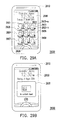
- FIG. 29A is a schematic diagram of a background corresponding to a background setting style of contacts according to an embodiment of the invention.
- FIG. 29B is a schematic diagram of a background corresponding to a background setting style of contacts according to an embodiment of the invention.
- FIG. 29C is a schematic diagram of a background corresponding to a background setting style of social network service according to an embodiment of the invention.
- FIG. 29D is a schematic diagram of a background corresponding to a background setting style of social network service according to an embodiment of the invention.
- FIG. 30A is a schematic diagram of a background corresponding to a background setting style of gallery according to an embodiment of the invention.
- FIG. 30B is a schematic diagram of a background corresponding to a background setting style of gallery according to an embodiment of the invention.
- FIG. 30C is a schematic diagram of a background corresponding to a background setting style of gallery according to an embodiment of the invention.
- FIG. 30D is a schematic diagram of a background corresponding to a background setting style of gallery according to an embodiment of the invention.
- FIG. 31A is a schematic diagram of a background corresponding to a background setting style of weather information according to an embodiment of the invention.
- FIG. 31B is a schematic diagram of a background corresponding to a background setting style of weather information according to an embodiment of the invention.
- FIG. 32A is a schematic diagram of a background corresponding to a background setting style of stock information according to an embodiment of the invention.
- FIG. 32B is a schematic diagram of a background corresponding to a background setting style of stock information according to an embodiment of the invention.
- FIG. 33 is a schematic diagram of a background corresponding to a background setting style of virtual clock according to an embodiment of the invention.
- FIGs 34 and 35 is a schematic diagram of a background corresponding to the background setting style of contacts according to an embodiment of the invention.
- FIG. 36 is a schematic diagram of a message editing screen according to an embodiment of the invention.
- FIG. 37 is a schematic diagram of a personalized menu according to an embodiment of the invention.
- FIG. 38 is a schematic diagram of a lock screen preview according to an embodiment of the invention.
- FIG. 39 is a schematic diagram of a group selection screen according to an embodiment of the invention.
- FIG. 40 is a schematic diagram of a group list screen according to an embodiment of the invention.
- FIG. 41 is a schematic diagram of a contacts list according to an embodiment of the invention.
- FIG. 42 is a schematic diagram of a contact card according to an embodiment of the invention.
- FIG. 43 is a schematic diagram of a action define screen according to an embodiment of the invention.
- FIG. 44 is a schematic diagram of a background corresponding to the background setting style of note according to an embodiment of the invention.
- FIG. 45 is a schematic diagram of a background corresponding to the background setting style of task according to another embodiment of the invention.
- FIG. 46 is a schematic diagram of a task reminder according to an embodiment of the invention.
- FIG. 47 is a flow chart of a method of providing a background of an electronic device according to an embodiment of the present invention.
- FIG. 1 is a block diagram of an electronic device according to an embodiment of the present invention.
- the electronic device 100 includes a touch screen 110, one or more processors 120, and a memory 130.
- the electronic device 100 is, for example, a mobile phone, a smart phone, a personal digital assistant (PDA), a laptop, a tablet personal computer (PC), or a digital camera, the present invention is not limited thereto.
- PDA personal digital assistant
- PC tablet personal computer
- digital camera digital camera
- the touch screen 110 may be a resistive touch screen, a capacitive touch screen, an optical touch screen, or a magnetic touch screen, which is not limited by the present invention.
- the touch screen 110 is used as an input and output interface for the electronic device 100. That is, the touch screen 110 is configured to display different visual output when using the electronic device 100, and to receive different touch operations from a user.
- the visual output may be the operating result and/or the operation image such as the home screen image, the lock screen image, or the graphical user interface of applications.
- the one or more processors 120 may be a central processing unit (CPU), which is configured to run various software programs and/or instruction sets stored in the memory 130 to perform different functions for the electronic device 100 and to process data after the electronic device 100 is powered on.
- CPU central processing unit
- the memory 130 may be an internal storage unit such as a random access memory or a non-volatile memory (e.g., a flash memory, or a magnetic disk storage device).
- the memory 130 may also be an external storage unit such as Secure Digital (SD) card, a SIM card, or other storage media which can be externally connected to the electronic device 100.
- SD Secure Digital
- SIM SIM card
- the memory 130 may further be a networked online storage that can be accessed through a communication network by a network component (not shown) of the electronic device 100.
- At least an operating system 131, and one or more programs 133 are stored in the memory 130.
- the operating system 131 includes various software components and/or drivers and is used for managing a general operation of the electronic device 100.
- the operating system 131 provides a user interface for users to interact with the electronic device 100, manages applications that are running on the electronic device 100, and manages files stored in the electronic device 100.
- the one or more programs 133 comprise instructions to be executed by the one or more processors 120.
- the one or more processors 120 run the one or more programs 133 to perform a method of controlling the electronic device 100 of the present embodiment. The controlling method of the present embodiment is described later with reference of figures.
- FIG. 2 is a flow chart of a method of controlling an electronic device according to an embodiment of the present invention. Please refer to Fig. 1 and Fig. 2 .
- the electronic device 100 is set to a user-interface lock state.
- the electronic device 100 may have a plurality of operation states including the user-interface lock state and a user-interface unlock state.
- the electronic device 100 In the user-interface lock state, the electronic device 100 is in operation but ignores most user input. That is, the electronic device 100 in the user-interface lock state may only respond to a predefined set of user inputs such as input that corresponds to an attempt to switch the electronic device 100 to the user-interface unlock state.
- the electronic device 100 can be operated by the user normally. That is, general functions supported by the electronic device 100 can be invoked, and all kinds of user input from the touch screen 110 or the other input device (e.g., a hardware button, a key, or a scroll wheel) can be responded by the electronic device 100.
- general functions supported by the electronic device 100 can be invoked, and all kinds of user input from the touch screen 110 or the other input device (e.g., a hardware button, a key, or a scroll wheel) can be responded by the electronic device 100.
- step S210 a part of inner area of an unlock ring is displayed on the touch screen 110 while the electronic device 100 is in the user-interface lock state.
- the unlock ring is formed by two geometric patterns in which one geometric pattern is wholly contained by the other one, the area of the smaller geometric pattern is the inner area of the unlock ring, and a part of the inner area is invisible on the touch screen 110.
- the unlock ring has a circular shape (i.e., a circular unlock ring).
- the unlock ring may have a square shape, a rectangle shape, a rhombus shape, an elliptic shape, a star-shape, a heart shape, or a polygon shape.
- the type of two geometric patterns may be identical or different. That is to say, the look of the unlock ring is not limited in the present invention.
- step S220 a user input applied to the unlock ring on or near the touch screen 110 is detected.
- the user input is, for example, an object contact on or near the touch screen 110 close to the display position of the unlock ring.
- step S230 the unlock ring is moved in accordance with the user input. That is, the display position of the unlock ring is changed in accordance with the movement of the user input, and the visual feedback is provided to the user through the touch screen 110.
- the predetermined edge is an edge of the display area of the touch screen 110. That is, the predetermined edge may be a physical edge of the touch screen 110. In another embodiment, the predetermined edge may be an edge of an application window, an edge of a dialog box, or any virtual edge displayed on the touch screen 110.
- step S250 the electronic device 100 maintains in the use-interface lock state.
- the predetermined ratio is 100%.
- the unlock ring is moved in accordance with the detected user input, and if not all of the inner area of the unlock ring clear the predetermined edge at the time of the termination of the user input, the electronic device 100 remains in the use-interface lock state.
- step S260 the electronic device 100 transitions to a user-interface unlock state. Assuming that the predetermined ratio is 100%, the unlock ring is moved in accordance with the detected user input, and the electronic device 100 remains in the use-interface lock state until the user input is terminated while all of the inner area of the unlock ring clear the predetermined edge. Furthermore, in the present embodiment, the unlock ring is zoomed in on the touch screen 110 during the transition period. However, in another embodiment, the unlock ring is zoomed out on the touch screen 110 during the transition period. By applying a zoom-in animation effect or a zoom-out animation effect to the unlock ring, the user can clearly notice that the unlock action is done successfully.
- the predetermined ratio may be 95%, 90%, or other value. If the predetermined ratio is 90%, as long as nine-tenth of the inner area of the unlock ring cross the predetermined edge while the user input is terminated, the electronic device 100 transitions to a user-interface unlock state. It should be noted that while the unlock ring is released (i.e., the user input is terminated), whether the predetermined ratio of the inner area of the unlock ring is completely displayed on the touch screen 110 is not a necessary condition to transition the electronic device 100 to the user-interface unlock state.
- Fig. 3 is a flow chart of a method of controlling an electronic device according to another embodiment of the present invention.
- the steps in Fig. 3 are similar to those in Fig. 2 , and the difference between the two embodiments is that the step S240 in Fig. 2 is replaced by the step S340 in Fig. 3 .
- the similar steps in the two embodiments will not be described in detail herein.
- step S340 While the unlock ring is moved in accordance with the existent user input, if the user input is terminated, in step S340, whether the unlock ring is moved to make a predetermined ratio of the inner area of the unlock ring cross the predetermined edge and be displayed on the touch screen 110 is determined. For example, it is assumed that the predetermined ratio is 100%. Then, the electronic device 100 will transition to the user-interface unlock state only if the entire inner area of the unlock ring crosses the predetermined edge and is displayed on the touch screen 110.
- Figs. 4A-4D are schematic views illustrating the visual output while controlling an electronic device according to an embodiment of the invention.
- the predetermined ratio is, for example, 100%.
- a part of inner area 410 of an unlock ring 400 is displayed on the touch screen 110.
- the unlock ring 400 displayed on the touch screen 110 is divided by the down edge 4e of the touch screen 110, however, the initial position of the unlock ring 400 is not limited thereto.
- the predetermined edge is the down edge 4e.
- the user begins the unlock action by touching the unlock ring 400 with his/her hand and finger 420, and then the unlock ring 400 will be moved in accordance with the movement of the finger 420. If the user release the unlock ring 400 as the situation shown in Fig. 4B , the electronic device 100 remains in the user-interface lock state since a part of the inner area 410 is still below the down edge 4e, meanwhile, a unlock hint is displayed on the touch screen 110.
- the unlock hint is, for example, a text hint which describes how to unlock the touch screen 110.
- the unlock hint may fade out if no user input has been detected for a certain amount of time (e.g., 5 seconds).
- the electronic device 100 will transition to the user-interface unlock state since all of the inner area 410 of the unlock ring 400 clears the down edge 4e.
- the electronic device 100 will transition to the user-interface unlock state as long as the entire inner area 410 crosses the down edge 4e, even if there is a portion of inner area 410 does not be displayed on the touch screen 110.
- the electronic device 100 will transition to the user-interface unlock state since all of the inner area 410 of the unlock ring 400 crosses the down edge 4e and is displayed on the touch screen 110.
- Figs. 5A-5D are schematic views illustrating the visual output while controlling an electronic device according to another embodiment of the invention.
- the electronic device 100 is in the user-interface lock state, and a part of inner area 510 of an unlock ring 500 is displayed on the touch screen 110.
- the position of the unlock ring 500 shown in Fig. 5A is called the initial display position.
- the electronic device 100 maintains in the user-interface lock state.
- a unlock hint will be displayed on the touch screen 110 in response to the user input that is not applied to the unlock ring 500.
- the unlock hint is a text hint 530 as shown in Fig. 5B .
- the instructional text hint 530 illustrates how to unlock the touch screen 110 to the user.
- the text hint 530 may be displayed near the unlock ring 500 or at the top of the touch screen 110.
- the position of displaying the text hint 530 is not limited in the present invention.
- the unlock hint is an animation hint that moves the unlock ring 500 in a direction that can make the predetermined ratio of inner area of the unlock ring 500 cross the predetermined edge 5e. Since the predetermined edge 5e is the down edge of the touch screen 110, as shown in Fig. 5C , the animation hint is performed in which the unlock ring 500 moves in an upward direction 540. It should be noted that the displacement of moving the unlock ring 500 during the animation is not limited in the present embodiment. The unlock ring 500 may not actually moved to make the entire inner area 510 cross the predetermined edge 5e. In the present embodiment, the unlock ring 500 moves to a predetermined position and then falls back to the initial display position. In another embodiment, the unlock ring 500 bounces when it falls back to the initial display position. In yet another embodiment, as shown in Fig. 5D , a ripple animation 550 is displayed around the unlock ring 550 when it falls back to the initial display position.
- the text and animation hint facilitates user to perform a correct unlock action even if the user is using the electronic device 100 for the first time.
- Figs. 6A-6C are schematic views illustrating the visual output while controlling an electronic device according to another embodiment of the invention.
- Fig. 6A besides a part of inner area of the unlock ring 600, four function images 610-640 are displayed outside the unlock ring 600 while the electronic device 100 is in the user-interface lock state. It should be noted that the number of the displayed function image is not limited in the present invention.
- the function images 610-640 are fading out gradually. This helps avoid improper user interaction with the function images 610-640 and the unlock ring 600. However, if the electronic device 100 does not transition to the user-interface unlock state within a predetermined time, the function images 610-640 fade in again.
- FIG. 7 is a block diagram of an electronic device according to an embodiment of the present invention.
- the electronic device 700 includes a touch screen 710, a memory 720, and one or more processors 130.
- the electronic device 700 is, for example, a mobile phone, a smart phone, a personal digital assistant (PDA), a laptop, a tablet personal computer (PC), or a digital camera, the present invention is not limited thereto.
- PDA personal digital assistant
- PC tablet personal computer
- digital camera the present invention is not limited thereto.
- the touch screen 710 may be a resistive touch screen, a capacitive touch screen, an optical touch screen, or a magnetic touch screen, which is not limited by the present invention.
- the touch screen 710 is used as an input and output interface for the electronic device 700. That is, the touch screen 710 is configured to display different visual output when using the electronic device 700, and to receive different touch operations from a user.
- the visual output may be the operating result and/or the operation image such as the home screen image, the lock screen image, or the graphical user interface of applications. While the electronic device 700 is in operation, movement of one or more objects on or near the touch screen 710 can be detected, and the corresponding signals are transmitted to the processor 730 to perform the related action on the electronic device 700, then the generated visual output is displayed on the touch screen 710.
- the memory 720 may be an internal storage unit such as a random access memory or a non-volatile memory (e.g., a flash memory, or a magnetic disk storage device).
- the memory 720 may also be an external storage unit such as Secure Digital (SD) card, a SIM card, or other storage media which can be externally connected to the electronic device 700.
- SD Secure Digital
- SIM SIM card
- the memory 720 may further be a networked online storage that can be accessed through a communication network by a network component (not shown) of the electronic device 700.
- At least an operating system 721, one or more applications 723, and one or more programs 725 are stored in the memory 720.
- the operating system 721 includes various software components and/or drivers and is used for managing a general operation of the electronic device 700.
- the operating system 721 provides a user interface for users to interact with the electronic device 700, manages applications 723 that are running on the electronic device 700, and manages files stored in the electronic device 700.
- the one or more applications 723 include, but not limited to, a phone application, an email application, a camera application, a message application, a contact application, a social network application, a financial application, an alarm application, or a calendar application.
- the applications 723 may be native applications pre-installed on the electronic device 700, or may be downloaded from third-party sites or online stores.
- the one or more programs 725 comprise instructions to be executed by the one or more processors 730.
- the one or more processors 730 run the one or more programs 725 to perform a method of controlling the electronic device 700 of the present embodiment.
- the controlling method of the present embodiment is described later with reference of figures.
- the one or more processors 730 may be a central processing unit (CPU), which is configured to run various software programs and/or instruction sets stored in the memory 720 to perform different functions for the electronic device 700 and to process data after the electronic device 700 is powered on.
- CPU central processing unit
- FIG. 8 is a flow chart of a method of controlling an electronic device according to the embodiment of the present invention. Please refer to Fig. 7 and Fig. 8 .
- the electronic device 700 is set to a user-interface lock state.
- the electronic device 700 may have a plurality of operation states including the user-interface lock state and a user-interface unlock state.
- the electronic device 700 In the user-interface lock state, the electronic device 700 is in operation but ignores most user input. That is, the electronic device 700 in the user-interface lock state may only respond to a predefined set of user inputs, including input that corresponds to an attempt to switch the electronic device 700 to the user-interface unlock state or input that applies to a function image displayed on the touch screen 710.
- the electronic device 700 can be operated by the user normally. That is, general functions supported by the electronic device 700 may be invoked, and all kinds of user input from the touch screen 710 or the other input device (e.g., a hardware button, a key, or a scroll wheel) can be responded by the electronic device 700.
- general functions supported by the electronic device 700 may be invoked, and all kinds of user input from the touch screen 710 or the other input device (e.g., a hardware button, a key, or a scroll wheel) can be responded by the electronic device 700.
- step S810 part or all of a ring and one or more function images outside the ring are displayed on the touch screen 710 while the electronic device 700 is in the user-interface lock state.
- the ring 900 is partially displayed on the touch screen 710, the displayed part of the ring 900 and at least one edge of the touch screen 710 (e.g., the edge 9e) form a closed area, and the one or more function images (e.g., the function images 910 and 920) are all displayed outside the closed area bounded by the ring 900.
- the one or more function images e.g., the function images 910 and 920
- the entire ring 900b is displayed on the touch screen 710, the ring 900b forms a closed area by itself, and the one or more function images (e.g., the function images 910b and 920b) are all displayed outside the ring 900b.
- Each function image displayed on the touch screen 710 corresponds to a predetermined function, and is preloaded in or acquired by the electronic device 700.
- the function image may be an application icon, a software button, or an image downloaded or captured by the user through the electronic device 700.
- the function image to be displayed on the touch screen 710 may be predetermined by the electronic device 700 or selected by the user.
- step S820 a user input applied to one function image on or near the touch screen 710 is detected.
- the user input is, for example, an object contact on or near the touch screen 710 associated with the position of the function image.
- step S830 the function image is moved in accordance with the user input. Therefore, while the user input is not terminated, the display position of the function image is changed in accordance with the movement of the user input, and the visual feedback is provided to the user through the touch screen 710. For example, as shown in Fig. 9C , while the user touches the function image 910 with his/her finger 930 and drags the function image 910, the display position of the function image 910 is different from the original position 910_OP thereof and is varied accordingly.
- step S840 it is determined that whether the function image is moved into the ring. That is, to determine whether the function image is moved into the closed area bounded by the ring.
- step S850 the electronic device 700 is maintained in the use-interface lock state. That is, only the user input corresponding to the attempt of switching the electronic device 700 to the user-interface unlock state or the input that applies to the displayed function image will be responded.
- step S860 the predetermined function corresponding to the function image is performed.
- the predetermined function corresponding to the function image is performed. For example, as shown in Fig, 3D , while the function image 910 is moved from its original position 910_OP into the ring 900, the predetermined function corresponding to the function image 910 is performed.
- the exemplars of performing the predetermined function corresponding to the function image are described in the followings.
- one or more function images (e.g., the function images 1010-1040) will be displayed on the touch screen 710 as long as the electronic device 700 is in the user-interface lock state, and the predetermined function corresponding to this kind of function image is to open a corresponding application.
- the application is, for example, a phone application, an email application, a camera application, or a message application, the present invention is not limited thereto. Accordingly, if the user drags this kind of function image into the ring 1000 while the electronic device 700 is in the user-interface lock state, the corresponding application will be launched automatically.
- the function images 1010-1040 are corresponding to the phone application, the email application, the camera application, and the message application respectively. Therefore, if one of the function images 1010-1040 is moved into the ring 1000, the corresponding application is then launched.
- the predetermined function corresponding to the function image displayed on the touch screen 710 as long as the electronic device 700 is in the user-interface lock state is to access a social networking service or a website.
- a social networking service or a website For example, referring to Fig. 11 , nine function images 1110-1190 are displayed outside the ring 1100 while the electronic device 700 is in the user-interface lock state.
- the function images 1110-1190 are acquired by the electronic device 700 from a certain social networking website through the network, and each of the function images 1110-1190 is corresponding to a user of the social networking website who is a friend of the user of the electronic device 700. If the user drags one of the function images 1110-1190 into the ring 1100 while the electronic device 700 is in the user-interface lock state, a main page of the website user corresponding to the dragged function image is then displayed on the touch screen 710.
- the function image that will be displayed on the touch screen 710 while the electronic device 700 is in the user-interface lock state is invoked by an occurrence of an event such as an incoming call, an alarm or a calendar reminder, etc. That is to say, in response to an occurrence of an incoming call, an alarm or a calendar reminder during the electronic device 700 is in the user-interface lock state, the one or more function images corresponding to the event are then displayed on the touch screen 710. At this time, if the user drags this kind of function image into the ring, an operation of the event will be executed. For example, as shown in Fig.
- Fig. 12A if one or more function images 1210 and 1220 are invoked by an occurrence of an incoming call, the user may answer or decline the incoming call by dragging the related function image 1210 or 1220 into the ring 1200.
- Fig. 12B if one or more function images 1230 and 1240 are invoked by an activation of an alarm, the user may snooze or dismiss the alarm by dragging the related function image 1230 or 1240 into the ring 1200.
- Fig. 12C if one or more function images 1250 and 1260 are invoked by an activation of a calendar reminder, the user may snooze or dismiss the calendar reminder by dragging the related function image 1250 or 1260 into the ring 1200.
- Figs. 13A-13H illustrate schematic diagrams while controlling an electronic device in the user-interface lock state according to an embodiment of the invention.
- ring 1300 when the electronic device 700 is in the user-interface lock state, the ring 1300 is partially displayed on the touch screen 710, wherein the displayed part of the ring 1300 and the edge 1311 of the touch screen 710 form a closed area.
- Fig. 13B two function images 1310 and 1320 are displayed outside the ring 1300 in response to the occurrence of the alarm event.
- the function image 1310 is corresponding to a snoozing operation
- the function image 1320 is corresponding to a dismissing operation.
- the ring 1300 is slightly moved toward the function image 1310 (e.g., along the direction 1340) in response to detecting the touch.
- the ring 1300 is slightly moved toward the function image 1320 (e.g., along the direction 1350) in response to detecting the touch. That is, the ring 1300 is slightly moved in response to detecting the static touch on the function image 1310 or 1320.
- Fig. 13E if the user taps the function image 1310 and then lifts his/her finger (or the input tool), the function image 1310 and the ring 1300 are moved toward each other.
- Fig. 13F if the user taps the function image 1320 and then lifts his/her finger (or the input tool), the function image 1320 and the ring 1300 are moved toward each other.
- a hint image of the function image being touched or tapped is displayed inside the ring 1300.
- a hint image 1360 corresponding to the function image 1310 is then displayed inside the ring 1300.
- the hint image 1360 may have the same shape and pattern with the function image 1310 but provides the grayscale effect.
- the appearance of the hint image is not limited in the present invention.
- to move the touched function image 1310 or 1320 and/or the ring 1300, and to show the corresponding hint image can provide hints or reminders of the operation to drag the function image 1310 or 1320 into the ring 1300 to the user.
- Figs. 14A-14C illustrate schematic diagrams while controlling an electronic device in the user-interface lock state according to another embodiment of the invention.
- a part of the ring 1400 and four function images 1410-1440 are displayed on the touch screen 710.
- the function images 1410-1440 are respectively corresponding to four applications.
- the applications are default applications predetermined by the electronic device 700.
- the number of function images being displayed is not limited in the present invention, in another word, the user may select one or more applications from all applications installed in the electronic device 700, and one or more function images corresponding to each application selected by the user will be displayed along with the ring 1400 while the electronic device 700 is in the use-interface lock state.
- the ring 1400 will move toward the touched function image. For example, as shown in Fig. 14A , it is assumed that the function image 1410 is touched by the user, the ring 1400 moves toward the function image 1410. As shown in Fig. 14B , if the function image 1440 is touched by the user, the ring 1400 moves toward the function image 1440.
- the tapped function image and the ring 1400 will move toward each other. Furthermore, a hint image of the touched or tapped function image is displayed inside the ring 1400 in response to detecting the user input applied on the function image.
- the electronic device 700 exits the use-interface lock state and the application (e.g. the phone application) corresponding to the function image 1410 is launched.
- the application e.g. the phone application
- the default view e.g., the default user interface
- the function image 1410 corresponds to the application which is already launched, the latest view of the application is displayed to present the latest operating result to the user.
- the ring displayed on the touch screen 710 while the electronic device 700 is in a user-interface lock state is a circular ring.
- the ring displayed on the touch screen 710 may have an elliptic shape, a polygon shape, or an irregular shape. That is, the shape of the ring is not limited by the present invention.
- the ring may have an elliptic shape as the ring 1500 shown in Fig. 15 .
- the ring may have a rectangle shape as the ring 1600 shown in Fig. 16 , a triangle shape as the ring 1700 shown in Fig. 17 , or a rhombus shape as the ring 1800 shown in Fig. 18 .
- the ring may have a heart shape as the ring 1900 shown in Fig. 19 .
- the background of an electronic device when it is in the user-interface unlock state is referred to as the home screen
- the main screen of the electronic device when it is in the user-interface lock state is referred to as the lock screen.
- a launch bar is displayed at the bottom of the home screen.
- the corresponding function image(s) of the shortcut icon(s) will be automatically displayed on the lock screen of the electronic device.
- the corresponding function images of these default shortcut icons will be displayed on the lock screen while the electronic device enters the user-interface lock state.
- the user may press-and-hold one shortcut icon on the launch bar and drag it over another shortcut icon on the launch bar to create a shortcut folder (these two shortcut icons are added into the shortcut folder), and the function image of the shortcut folder will be displayed on the lock screen.
- the user can add, delete, or organize the shortcut icon on the launch bar, and the lock screen will reflect the modification. That is, the function image(s) displayed on the lock screen will be synchronized and corresponding to the shortcut icon(s) and/or the shortcut folder(s) on the launch bar.
- three default shortcut icons 2010-2030 are displayed on a launch bar 2040, wherein the launch bar 2040 is at the bottom of the home screen 2000.
- the shortcut icons 2010-2030 are corresponding to an e-mail application, a web browser application, and a camera application, however, the type and the number of the default application is not limited thereto.
- the lock screen corresponding to the launch bar 2040 is shown in Fig. 21 .
- three function images 2110-2130 of the default shortcut icons 2010-2030 corresponding to the e-mail application, the web browser application, and the camera application are displayed on the lock screen 2100, and the application name is also displayed below each of the function images 2110-2130.
- Fig. 22 if the user drag a shortcut icon 2210 of the mail application to the launch bar 2040, the configuration of the lock screen 2100 will be changed automatically as shown in Fig. 23 , wherein the function image 2340 of the shortcut icon 2210 is displayed on the lock screen 2100 automatically.
- the displayed function images 2110-2130 and 2340 may be aligned and equally displayed on the lock screen 2100.
- the display manner of the function image is not limited thereto.
- three shortcut icons 2410-2430 are displayed on the launch bar 2040. If the user press-and-hold the shortcut icon 2440 of camera application, and drag it onto the shortcut icon 2450 of web browser application, then, the shortcut icons 2440 and 2450 of two applications become a folder with a default folder name "Unnamed Folder" (the folder name can be changed by the user).
- the launch bar 2040 now has three shortcut icons 2410-2430 and one shortcut folder 2460 displayed thereon. Accordingly, while the electronic device enters the user-interface lock state, the function images 2510-2530 corresponding to the shortcut icons 2410-2430 and the function image 2560 corresponding to the shortcut folder 2460 are displayed on the lock screen 2100 as shown in Fig. 25 . The user may drags any function image into the ring to launch it.
- the appearance of the shortcut icon or the shortcut folder displayed on the launch bar may be visually different from the corresponding function image displayed on the lock screen.
- the function image of a shortcut icon (or a shortcut folder) on the lock screen is displayed with the name of the application corresponding to the function image (or the folder name of the shortcut folder) while the shortcut icon or the shortcut folder in the launch bar is not, or vice versa.
- the displaying sequence of the function images of the shortcut icons/folders in the lock screen and the displaying sequence of the shortcut icons/folders in the launch bar may be different.
- the invention provides a method for providing a background of a locked screen, an electronic device and a computer program product using the same according to the above point of view.
- FIG. 26 is a block diagram of an electronic device according to an embodiment of the invention.
- the electronic device 2600 of the present embodiment includes a screen 2610, a memory 2620 and one or more processing units 2630, where the one or more processing units 2630 are coupled to the screen 2610 and the memory 2620.
- the electronic device 2600 is, for example, a mobile phone, a smart phone, a personal digital assistant (PDA), a laptop computer, a tablet personal computer (PC), a digital camera, an electronic book or a game machine, etc., which is not limited by the invention.
- the screen 2610 may be any type of a touch screen, for example, a resistive touch screen, a capacitive touch screen, an optical touch screen, an acoustic wave touch screen, an electromagnetic touch screen, etc., though the invention is not limited thereto.
- the screen 2610 having a touch control function can serve as an input/output interface of the electronic device 2600. Namely, the screen 2610 may be used to receive a touch input from the user, and may be used to display information of the electronic device 2600. The information may be operation interfaces of various applications, widgets, services or functions and generated information contents.
- the screen 2610 can also be a liquid crystal display (LCD) that only has the display function, and the user has to perform input through an input device such as a hardware button or a keyboard, etc.
- LCD liquid crystal display
- the memory 2620 may be an internal storage unit or an external storage unit.
- the internal storage unit may be a random access memory (RAM), a read-only memory (ROM), a flash memory, or a magnetic disk storage device, etc.
- the external storage unit may be a compact flash (CF) memory card, a secure digital (SD) memory card, a micro SD memory card, or a memory stick (MS), etc., and the external storage unit is connected to the electronic device 2600 through a corresponding interface.
- the memory 2620 can also be a network storage space, and the electronic device 2600 may connect and access the network storage space through a network by using a network device (not shown).
- the memory 2620 stores one or more programs 2640 and an operating system 2650. Moreover, the memory 2620 may also store various applications (not shown) and widgets (not shown) that can be executed on the electronic device 2600, and software components (not shown) required in operation.
- the one or more programs 2640 include one or more instructions. Further, the one or more processing units 2630 execute the instructions included in the one or more programs 2640 to implement a method for providing a background of a locked screen of the present embodiment, so as to generate the background displayed on the screen 2610 when the electronic device 2600 is in the user-interface lock state.
- Each of the one or more processing units 2630 may be a central processing unit (CPU), a programmable microprocessor, a digital signal processor (DSP), a programmable controller, an application specific integrated circuit (ASIC), a programmable logic device (PLD) or other similar devices. In this way, when the electronic device 2600 is activated, the one or more processing units 2630 can execute the one or more programs 2640 stored in the memory 2620 and/or other software installed in the electronic device 2600.
- FIG. 27 is a flowchart illustrating a method for providing a background of a locked screen according to an embodiment of the invention.
- the electronic device 2600 of the present embodiment has the user-interface lock state and a user-interface unlock state. It is assumed that the screen 2610 serves as an input interface (for example, a touch screen) of the electronic device 2600.
- the electronic device 2600 When the electronic device 2600 is in the user-interface lock state, the electronic device still continually operates, and when the user touches the screen 2610, the electronic device 2600 ignores most of touch signals generated by the user input.
- the electronic device 2600 can only receive predetermined touch signals including a predetermined touch signal used for switching the user-interface lock state/the user-interface unlock state, and a predetermined touch signal used for switching display data on the background displayed on the screen 2610.
- the electronic device 2600 when the electronic device 2600 is in the user-interface unlock state, the user can normally operate the electronic device 2600. Namely, functions and services supported by the electronic device 2600 and applications and widgets installed in the electronic device 2600 can all be called and used.
- the electronic device 2600 in the user-interface unlock state can receive a signal input through the screen 2610 and generate a corresponding operation result. Signals input through other input devices can also be processed by the electronic device 2600 in the user-interface unlock state.
- a selection of a background setting style is received.
- the electronic device 2600 has a plurality of background setting styles for selection, where each of the background setting styles corresponds to a widget, an application, a function or a service provided by the electronic device 2600.
- the background setting styles may include an application shortcut style, a contacts style, a social network service style, a gallery style, weather information style, stock information style, a virtual clock style, a note style, or a task style, etc., though the invention is not limited thereto.
- the electronic device 2600 may also have other background setting styles for selection.
- the user may select the background setting style when the electronic device 2600 is in the user-interface unlock state.
- the electronic device 2600 may analyse a usage habit of the user to automatically select the background setting style.
- step S2705 when the electronic device 2600 enters the user-interface lock state, one or more display data are obtained from a storage device according to the currently selected background setting style.
- the storage device of the present embodiment may be a remote storage device or a local storage device.
- the remote storage device is, for example, an online storage
- the local storage device may be built in or externally connected to the electronic device 2600, which is, for example, a built in hard disk, a portable memory device (e.g., a pen drive), or a memory card, etc.
- a type of the display data corresponds to the selected background setting style.
- the display data corresponding to the application shortcut style include a picture file serving as a wallpaper and one or more applications the function image of the shortcut icon of the applications will be displayed.
- the display data corresponding to the contacts style or social network service style include contacts information and/or dynamic information shared to a community website by friends.
- the display data corresponding to the gallery style include photos and images.
- the display data corresponding to the weather information style include a current temperature, a weather status, a rain rate, a future/past weather report, etc.
- the display data corresponding to the stock information style includes a stock market content, such as stock price, stock quote, market trend, a stock trend, futures, and a classification option price and Hong Kong Shanghai and Shenzhen stocks, etc.
- the display data corresponding to virtual clock style includes a minute, a second and a date of time.
- the one or more display data are, for example, obtained from a remote storage device corresponding to the background setting styles through a network, or the one or more display data are directly obtained from the local storage device.
- a background of the electronic device 2600 in the user-interface lock state is generated by using a template corresponding to the background setting style and the obtained display data.
- the display data on the background changes as time changes. Namely, when the electronic device 2600 is in the user-interface lock state, the background displayed on the screen 2610 is no longer a pure picture file, but presents different types of display data according to the selection of the background setting style, and the various types of display data is presented according to the template corresponding to the background setting style, and a content and/or a presenting manner of the display data changes as time changes.
- the background generated according to the background setting style does not include information such as a signal strength, a remaining power, a name of a telecommunication practitioner, and a time/date, etc. that are constantly displayed on the electronic device 2600 regardless whether the electronic device 2600 is in the user-interface lock state or the user-interface unlock state.
- the user can obtain more diversified information through the background when the electronic device 2600 is in the user-interface lock state.
- Different background setting styles are described in detail below.
- FIG. 28A is a schematic diagram of a background corresponding to a background setting style of application shortcut according to an embodiment of the invention.
- the user selects the application shortcut style as the background setting style.
- the obtained one or more display data include a picture file serving as the wallpaper and function images of shortcut icons of applications to be displayed (for example, obtained from the local storage device), and the background generated according to the template is shown as a background 2800 of FIG. 28A .
- the background 2800 includes function images 2822, 2824, 2826 and 2828 corresponding to the applications of phone call, email, camera and message, etc., though the types of the applications are not limited thereto.
- the electronic device 2600 may provide a plurality of predetermined applications (for example, phone call, email, camera, message, file browser, web browser, multimedia player, calculator, calendar, and music, etc.), and the user can select at least one predetermined application when the electronic device 2600 is in the user-interface unlock state.
- predetermined applications for example, phone call, email, camera, message, file browser, web browser, multimedia player, calculator, calendar, and music, etc.
- the user can quickly activate an application by operating a corresponding function image displayed on the background 2800, and the electronic device 2600 accordingly leaves the user-interface lock state.
- the user may drags the function image 2822 corresponding to the phone call application into the ring 2830, so as to launch the phone call application instantly.
- the user may drags the ring 2830 onto the function image 2824 corresponding to the email application to launch the email application instantly.
- the user may drags the ring 2830 and the function image 2826 corresponding to the camera application at the same time and makes the ring 2830 and the function image 2826 approach each other to immediately launch the camera application.
- the one or more display data may further include a message that can be accessed or generated by the application that the function image of the shortcut icon thereof should be displayed, and information related to the above message is displayed in form of a mark icon (for example, mark icons 2822-b, 2824-b and 2828-b) together with the function image.
- a mark icon for example, mark icons 2822-b, 2824-b and 2828-b
- the mark icon 2824-b represents the number of unread emails in an inbox. In this way, when the electronic device 2600 is in the user-interface lock state, the user can learn the number of unread emails according to the function image 2824 and the mark icon 2824-b displayed in the background 2800.
- the four function image s 2822, 2824, 2826 and 2828 are illustrated for corresponding to four selected predetermined applications, the number and types of the predetermined applications are not limited thereto, and when the electronic device 2600 enters the user-interface lock state, as long as the background displayed on the screen 2610 includes a function image of a shortcut icon of one or more predetermined application, it is considered to be within the scope of the invention.
- the obtained one or more display data further include a lock screen widget corresponding to an application being executed on the electronic device 2600.
- a lock screen widget corresponding to an application being executed on the electronic device 2600 When the user drags the lock screen widget into the ring displayed on the screen 2610, the application corresponding to the lock screen widget is launched immediately.
- FIG. 28B is a schematic diagram of a background corresponding to a background setting style of application shortcut according to this embodiment of the invention. It is assumed that a music application is executed on the electronic device 2600, and once the electronic device 2600 enters the user-interface lock state, besides the function images 2822, 2824, 2826 and 2828, a lock screen widget 2832 corresponding to the music application is also displayed on the background 2800. If the user drags lock screen widget 2832 into the ring 2830, the corresponding music application is launched and a now playing screen (e.g., the latest view of the user interface of the music application) of the music application is displayed on the screen 2610.
- a now playing screen
- displaying a lock screen widget on the background of the electronic device 2600 in the user-interface lock state is not limited by the background setting style. That is, no matter what kind of background setting style is being selected (or no background setting style is being selected), as long as an application installed in the electronic device 2600 is executed and the corresponding lock screen widget is displayed on the background of the electronic device 2600 in the user-interface lock state, so that the application can be launched by moving the lock screen widget into the ring displayed on the background, moving the ring onto the lock screen widget, or moving both of the ring and the lock screen widget to make them approach each other within a predetermined distance, it is considered to be within the scope of the invention.
- 28C is a schematic diagram of a background corresponding to no background setting style is being selected according to an embodiment of the invention.
- a lock screen widget 2832 corresponding to an application e.g., the music application
- the application can be instantly launched in the same or similar way as described above.
- FIG. 28D is a flowchart illustrating a method of controlling an electronic device according to an embodiment of the invention.
- step S2810 part or all of a ring and one or more function images outside the ring are displayed on the touch screen 2610 while the electronic device 2600 is in the user-interface lock state (as shown in Figs. 28A-28C ).
- step S2820 a user input applied to the function image and/or the ring on or near the touch screen 2610 is detected.
- the function image and/or the ring will be moved in accordance with the user input, wherein the function image corresponds to an application.
- step S2840 it is determined that whether the function image and the ring approach each other within a predetermined distance. For instance, it is determined that whether the function image is moved into the ring, whether the ring is moved onto the function image, or whether the function image and the ring are approached to each other within the predetermined distance. If the determination result of the step S2840 is negative, that is , the function image and the ring do not approach each other within the predetermined distance, in step S2850, the electronic device 2600 maintains in the user-interface lock state. If the determination result of the step S2840 is affirmative, in step S2860, the electronic device 2600 transition to a user-interface unlock state and the application corresponding to the function image is launched.
- FIG. 29A is a schematic diagram of a background corresponding to a background setting style of contacts according to an embodiment of the invention.
- the corresponding one or more display data include contacts information recorded in the local storage device of the electronic device 2600, which may be names and/or profile photos of the contacts, and various contact manners (for example, phone numbers, email boxes, joined community websites, personal web pages, and instant messaging accounts, etc.).
- contacts information recorded in the local storage device of the electronic device 2600, which may be names and/or profile photos of the contacts, and various contact manners (for example, phone numbers, email boxes, joined community websites, personal web pages, and instant messaging accounts, etc.).
- contacts of a specific group are selected from all of the contacts, and the corresponding contact information is regarded as the display data to generate a background 2900 displayed on the screen 2610 when the electronic device 2600 is in the user-interface lock state.
- the template corresponding to the contact displays one or a plurality of contact information belonging to a specific group in the background 2900.
- profile photos 2921-2929 respectively represent 9 contacts belonging to a same specific group, and a tag at a lower left/right corner of each of the profile photos represents a contact manner.
- this contact has two contact manners, where a tag 2923-a represents that such contact uses a specific community website, and a tag 2923-b represents that such contact has a phone number.
- the template limits the background 2900 to simultaneously display 9 contacts, though the number of the contacts is not limited thereto, and in other embodiments, along with different templates, an upper limit of the number of the contacts displayed in the generated background may be different.
- the other template only displays 2, 4, or 5 contacts in the background.
- a plurality of pages of the backgrounds may be generated, and the number of the contacts in each page of the background does not exceed the upper limit of the number of the contacts.
- the electronic device 2600 switches an up/down page of the backgrounds to display different contact information.
- the generated background is shown as a background 2950 of FIG. 29B .
- the background 2950 includes an error message 2931 to notify the user the above situation.
- FIG. 29C is a schematic diagram of a background corresponding to a background setting style of social network service according to an embodiment of the invention.
- a remote storage device for example, a server
- a community website or a network service is logged on through a network according to user identification (ID) information (for example, user account or password) recorded in the electronic device 2600, and then the contacts information are obtained from the community website or the service webpage to serve as the display data.
- ID user identification
- the obtained contacts information may be dynamic information (for example, photos, videos, texts, or links) shared to the community website or the service webpage by others.
- the background 2970 includes three sets of contact information 2932, 2934 and 2936, and each contact information includes a representative picture and name of the contact, and a message content shared to the community website.
- the electronic device 2600 automatically accesses the remote storage device that provides the community website every a predetermined time, so as to obtain latest contact information to serve as the display data.
- presenting manners such as display positions and sizes of all of the obtained contact information dynamically change as time changes, for example, the contact information 2932, 2934 and 2936 are automatically and alternately enlarged and displayed at the center of the screen 2610 clockwise.
- the electronic device 2600 can also switch the contact information 2932, 2934 and 2936 according to an operation instruction input by the user.
- the user can still check different contact information by inputting the operation instructions.
- the user can still conveniently and opportunely view dynamic information on the community website through the background 2970 displayed on the screen 2610.
- the user can drag any one of the contact information 2932, 2934 and 2936 down into the ring 400 and unlock directly to the source Social app.
- the background displayed on the screen 2610 of the electronic device 2600 is shown as a background 48 of FIG. 29D , which includes an error message 2933 to notify the user the above situation.
- FIG. 30A is a schematic diagram of a background corresponding to a background setting style of gallery according to an embodiment of the invention.
- the user selects the gallery style as the background setting style.
- the obtained one or more display data may include photos in a specific photo album.
- the specific photo album may be selected by the user when the electronic device 2600 is in the user-interface unlock state.
- the specific photo album may be a network photo album provided by a remote storage device (for example, a network storage space), and user ID information has to be used to log on the network photo album through a network, so as to obtain the photos stored therein.
- the specific photo album can also be a photo album in a local storage device (for example, a memory card) of the electronic device 2600.
- a background 3000 of the electronic device 2600 is generated according to a template of the gallery style and photos 3020, 3022, 3024 and 3026, though the number of the photos are not limited thereto.
- a presenting manner of the photos 3020, 3022, 3024 and 3026 serving as the display data change as time changes.
- each of the photos automatically moves towards a specific direction.
- the presenting manner such as a size, a display position or clarity of each of the photos changes as time changes.
- a moving direction of each of the photos also changes as time changes, so that the photos are displayed in form of the slide in different moving directions. It should be noticed that the invention is not limited to the display effect of the slide, and in other embodiments, the obtained photos may have different display effects as time changes.
- the user can also switch the obtained photos during the user-interface lock state of the electronic device 2600 by inputting an operation instruction.
- the background 3000 may display different photos, and multiple display effects are presented during a switching process of the photos.
- the background displayed in the screen 2610 includes an error message to notify the user a reason why the photos cannot be obtained.
- the error message may include prompt message such as "No photos found, please select another photo album".
- an error message 3031 in a background 3030 is, for example, prompt message such as "An error was encountered on your memory card" to notify the user a reason of the error occurrence.
- an error message 3032 in a background 3040 is, for example, prompt message such as "Please insert a memory card”.
- the user can connect the electronic device 2600 to other devices through the USB interface for data accessing.
- the electronic device 2600 may be used as a flash drive.
- the electronic device 2600 is in the user-interface lock state, if the electronic device 2600 is connected to the other device through the USB interface, the photos cannot be obtained from the local storage device of the electronic device 2600 for displaying.
- the background is shown as a background 3050 of FIG. 30D , in which an error message 3033 is, for example, prompt message such as "Your content is inaccessible because your phone is being used as USB storage. Disconnect USB to access your content".
- FIG. 31A is a schematic diagram of a background corresponding to a background setting style of weather information according to an embodiment of the invention.
- the user selects the weather information style as the background setting style.
- the obtained one or more display data may include a current temperature, a weather status, a rain rate, a past weather report, a future weather forecast, etc.
- the electronic device 2600 may be connected to a weather report release center through the network to obtain a content of the latest weather information, and displays the obtained display data according to a template of the weather information.
- the electronic device 2600 obtains the latest weather information to serve as the display data every a predetermined time, and opportunely displays the display data on a background 3100.
- the template displays today's temperature and weather status in the center of the background 3100, and displays the weather information of future several days (for example, four days, though the invention is not limited thereto) at a lower part of the background 3100 by icons 3122, 3124, 3126 and 3128, though the template of the weather information is not limited thereto.
- the electronic device 2600 enters the user-interface lock state, the user can still directly obtain the dynamic whether information through the background 3100 of the electronic device 2600 at any time.
- a background 3130 displays an error message 3131 to notify the user, where the error message 3131 is, for example, prompt message such as "No weather data available".
- FIG. 32A is a schematic diagram of a background corresponding to a background setting style of stock information according to an embodiment of the invention.
- the user selects the stock information style as the background setting style.
- the obtained one or more display data may include stock names/codes pre-selected by the user and the corresponding stock prices, etc., and the background generated according to the template is shown as a background 3200 of FIG. 32A .
- the electronic device 2600 may be connected to a stock release center through the network to obtain a latest stock content, and displays the obtained display data according to a template of the stock information. In an embodiment, as the stock price goes up and down, the corresponding stock name moves towards different directions.
- the electronic device obtains the latest stock information every a predetermined time, and accordingly updates a content of a background 3200. In this way, even if the electronic device 2600 enters the user-interface lock state, the user can still directly obtain the dynamic stock information through the screen 2610 of the electronic device 2600 at any time.
- the generated background is shown as a background 3250 of FIG. 32B , and the background 3250 displays an error message 3231 of "No stocks found".
- FIG. 33 is a schematic diagram of a background corresponding to a background setting style of virtual clock according to an embodiment of the invention.
- the obtained display data may include time, date and appearance setting of the virtual clock.
- the appearance setting of the virtual clock includes various different digital clocks and analog clocks, which may be selected by the user when the electronic device 2600 is in the user-interface unlock state.
- the background generated according to the template is shown as a background 3300 of FIG. 33 .
- the template displays the virtual clock at the center of the background 3300. It should be noticed that the background 3300 may provide a three-dimensional (3D) display effect, and present a vivid 3D virtual clock along with movement of the electronic device 2600.
- the user can define a contact group for a background corresponding to a background setting style of contacts in settings.
- a contact image of at least one contact in the group will be displayed on the background of the electronic device when it is in the user-interface lock state.
- On each contact image a default action icon of a default action corresponding to the contact is shown if the default action is defined for the contact. However, if the contact is not corresponding to any default action, only the contact image of the contact will be displayed.
- Fig. 34 is a schematic diagram of a background corresponding to the background setting style of contacts according to an embodiment of the invention.
- a contact group of four contacts is selected to generate the background corresponding to the background setting style of contacts.
- the number of contacts in the selected group is not limited.
- at most 9 contacts can be displayed in a page of the background corresponding to the background setting style of contacts. That is, it can have different layouts for 1-9 contacts, and if the selected group has more than 9 contacts, the user may scroll to next or pervious page to see other contacts in the group.
- a default action has been set to each of the contacts corresponding to the upper-left contact image 3410, the lower-left contact image 3420, and the lower-right contact image 3430, the default action icon representing each default action is respectively shown in the circles 3410-a, 3420-a and 3430-a.
- no default action has been set to the contact corresponding to the upper-right contact image 3440, so there is no additional default action icon on the contact image 3440.
- the default action of each contact may be making a phone call, sending a short message, sending an e-mail, or viewing the details of the contact.
- the default action is not limited therein.
- the default action set to the contact corresponding to the lower-left contact image 3420 is sending a short message.
- the electronic device is unlocked and the user interface of the SMS application is launched for the user to edit the message as shown in Fig. 36 .
- the user may edit the message, attach a file, and send the message by press the button 3600.
- the user can drag the contact image of the contact into the ring to unlock the locked device and launch the default action directly.
- a contact image of a contact that has not been set to any default action e.g., the contact corresponding to the upper-right contact image 3440 as shown in Fig. 35
- a action define screen e.g., the default action setting screen 4300 as shown in Fig. 43
- the contact image is dragged into the ring 3500.
- a default action icon of the assigned default action will be displayed along with the contact image of the contact.
- a system pre-defined default action will be launched if the user drags the contact image of a contact without default action into the ring. That is, the system pre-defined default action is assigned to the contact without any user selected default action, and a pre-defined default action icon corresponding to the system pre-defined default action is displayed on the contact image of the contact.
- the user may select one or more contacts from the contacts list instead of selecting a group to generate the background corresponding to the background setting style of contacts.
- the electronic device displays a lock screen preview as shown in Fig. 38 . If the user press the "Setting" button 3810, the group selection screen 3900 as shown in Fig. 39 is launched. Then, the user may select any group displayed on the group selection screen 3900, such as the "Friends" group.
- the user may add a new group by pressing the button 4010 in the toolbar 4000. Select one group in the group list to check the contacts in that group.
- the contacts list is shown in Fig. 41 . The user can tap on each contact in the contacts list to view the contact card.
- the contact card records the detail setting of each contact. As shown in Fig. 42 , the name/contact image/phone number/group/ringtone and other settings are all displayed on the contact card 4200. The user can tap on the option 4210 to launch the default action setting screen 4300 as shown in Fig. 43 . Then, the user may select one of the default actions to the contact.
- FIG. 47 is a flow chart of a method of providing a background of an electronic device according to an embodiment of the present invention.
- step S4710 one or more contact groups for selection are displayed while the electronic device is in a user-interface unlock state.
- step S4720 a touch input applied to a contact group of the one or more contact groups on or near the touch screen is detected.
- step S4730 in response to detecting the touch input applied to the contact group on or near the touch screen, the contact group is selected to display a contact image of a contact in the contact group on the touch screen while the electronic device is in a user-interface lock state.
- Fig. 44 is a schematic diagram of a background corresponding to the background setting style of note according to an embodiment of the invention.
- four function images 4410-4440 and at least a part of a ring 4450 are displayed on the screen of the electronic device.
- Each of the function images 4410-4440 is corresponding or related to a note taking function.
- the function image 4410 is corresponding to a function of creating a note
- the function image 4420 is corresponding to a function of creating a note and starting recording
- the function image 4430 is corresponding to a function of opening a camera function for capturing a photo or video and adding the photo or video into the new note
- the function image 4440 is corresponding to a function of searching notes.
- the user may touch one of the function images 4410-4430 with his/her finger and drags the touched function image into the ring 4450, then the note taking function corresponding to the function image dragged into the ring 4450 will be launched.
- the function image 4410 into the ring 4450 a screen for editing a new note and the software input panel (SIP) such as a software keyboard will be displayed.
- SIP software input panel
- a microphone will be turned on to record audio and add the recorded voice code into the new note.
- the camera function will be launched for capturing a photo or video to be added into a new note.
- the user may touch the ring 4450 and drag the ring 4450 to the function images 4410-4430 to launch the functions corresponding to the function images 4410-4430.
- the user may touch the function image 4440 with his/her finger and drags the function image 4440 into the ring 4450, then the screen for searching the note will be launched.
- Fig. 45 is a schematic diagram of a background corresponding to the background setting style of task according to an embodiment of the invention.
- a task list 4510 is displayed while the electronic device is in the user-interface lock state, wherein the maximum number of tasks that can be shown in the task list 4510 is, for example, 10.
- the maximum number of tasks that can be shown in the task list 4510 is, for example, 10.
- a notification is shown at the bottom of the task list 4510.
- the user has to unlock the electronic device to see the remaining tasks.
- two function images 4610 and 4620 are invoked accordingly.
- the user may snooze or dismiss the task reminder by dragging the related function image 4610 or 4620 into the ring 4500 or by dragging the ring 4500 to the related function images 4610 or 4620.
- An embodiment of the invention provides a computer program product, in which the computer program product comprises a computer readable storage medium and an executable computer program mechanism embedded therein. After the computer program mechanism is executed by an electronic device having a screen, the electronic device can achieve the effects illustrated in the afore-described embodiments.
- the computer readable storage medium may be a read only memory, a random access memory, a magnetic tape, a floppy disk, a hard disk, an optical disk, or a transmission medium, etc.
- the computer program product may be directly provided through a network transmission, which is not to be limited by invention herein.
Abstract
Description
- The invention relates to a method for providing a background, an electronic device and a computer program product using the same. Particularly, the invention relates to a method for providing a screen lock background, an electronic device and a computer program product using the same.
- With development of technology, in a current information society, people increasingly depend on electronic products. To cope with a demand of high working frequency, high efficiency, and features of lightness, slimness, shortness and smallness of the electronic products, utilization of various portable electronic devices such as notebook personal computers (PC), mobile phones, personal digital assistants (PDA), smart phones, pocket PC and tablet PC, etc. becomes popular. However, regarding the portable mobile device requiring features of lightness, slimness, shortness and smallness, a size thereof is strictly limited, so that a touch screen technique is developed to integrate a keyboard with a screen to serve as an input interface of the portable electronic device, so as to save cost of a conventional keyboard and an area occupied by the conventional keyboard.
- Although it is quite convenient to operate the electronic device through the touch screen, a user may inadvertently touch a screen key displayed on the touch screen to execute a specific function, for example, a call function of the electronic device by accident. Therefore, the mobile device has a user-interface lock state to prevent the user from miss-touching the touch screen to activate an unnecessary function. In other words, when the user does not need to operate the electronic device, the user can manually set the electronic device to a user-interface lock state, so as to lock an input function of the touch screen. Alternatively, when a non-operation time of the electronic device reaches a predetermined value, the user-interface lock state is automatically activated to prevent the situation of miss-touching.
- Generally, a background presented by the electronic device in the user-interface lock state is a single picture file, and even the user selects a different picture file according to his preference, it still looks dull to only use the picture as a background frame, and a usage fun is not effectively improved.
- The invention provides a method of providing a background of an electronic device with a touch screen. The method includes displaying one or more contact groups for selection while the electronic device is in a user-interface unlock state, detecting a touch input applied to a contact group of the one or more contact groups on or near the touch screen, and in response to detecting the touch input applied to the contact group on or near the touch screen, selecting the contact group to display a contact image of a contact in the contact group on the touch screen while the electronic device is in a user-interface lock state.
- The invention provides an electronic device including a touch screen, a memory, one or more processing units and one or more programs. The program is stored in the memory, and the processing unit executes one or more instructions of the program, where the instructions includes the steps of displaying one or more contact groups for selection while the electronic device is in a user-interface unlock state, detecting a touch input applied to a contact group of the one or more contact groups on or near the touch screen, and in response to detecting the touch input applied to the contact group on or near the touch screen, selecting the contact group to display a contact image of a contact in the contact group on the touch screen while the electronic device is in a user-interface lock state.
- The invention provides a computer program product, which includes a computer readable storage medium. The computer readable storage medium records one or more instructions. After the instructions is loaded to an electronic device, following steps are executed. One or more contact groups for selection are displayed while the electronic device is in a user-interface unlock state. A touch input applied to a contact group of the one or more contact groups on or near the touch screen is detected. In response to detecting the touch input applied to the contact group on or near the touch screen, the contact group is selected to display a contact image of a contact in the contact group on the touch screen while the electronic device is in a user-interface lock state.
- In order to make the aforementioned and other features and advantages of the invention comprehensible, several exemplary embodiments accompanied with figures are described in detail below.
- The accompanying drawings are included to provide a further understanding of the invention, and are incorporated in and constitute a part of this specification. The drawings illustrate embodiments of the invention and, together with the description, serve to explain the principles of the invention.
-
FIG. 1 is a block diagram of an electronic device according to an embodiment of the present invention. -
FIG. 2 is a flow chart of a method of controlling an electronic device according to an embodiment of the present invention. -
FIG. 3 is a flow chart of a method of controlling an electronic device according to another embodiment of the present invention. -
FIGs. 4A-4D are schematic views illustrating the visual output while controlling an electronic device according to an embodiment of the invention. -
FIGs. 5A-5D are schematic views illustrating the visual output while controlling an electronic device according to another embodiment of the invention. -
FIGs. 6A-6C are schematic views illustrating the visual output while controlling an electronic device according to still another embodiment of the invention. -
FIG. 7 is a block diagram of an electronic device according to an embodiment of the present invention. -
FIG. 8 is a flow chart of a method of controlling an electronic device according to an embodiment of the present invention. -
FIGs. 9A-9D ,10, 11, 12A-12C, 13A-13H, 14A-14C are schematic views illustrating the visual output while controlling an electronic device in the user-interface lock state according to several embodiments of the invention. -
FIGs. 15-19 are schematic views illustrating a ring displayed on the touch screen while an electronic device is in the user-interface lock state according to other embodiments of the invention. -
FIGs. 20 ,22 and24 are schematic views illustrating a home screen of an electronic device according to embodiments of the invention. -
FIGs. 21 ,23 and25 are schematic views illustrating a lock screen of an electronic device according to embodiments of the invention. -
FIG. 26 is a block diagram of an electronic device according to an embodiment of the invention. -
FIG. 27 is a flowchart illustrating a method for providing a background of a locked screen according to an embodiment of the invention. -
FIG. 28A is a schematic diagram of a background corresponding to a background setting style of application shortcut according to an embodiment of the invention. -
FIG. 28B is a schematic diagram of a background corresponding to a background setting style of application shortcut according to another embodiment of the invention. -
FIG. 28C is a schematic diagram of a background corresponding to no background setting style is being selected according to an embodiment of the invention. -
FIG. 28D is a flowchart illustrating a method of controlling an electronic device according to an embodiment of the invention. -
FIG. 29A is a schematic diagram of a background corresponding to a background setting style of contacts according to an embodiment of the invention. -
FIG. 29B is a schematic diagram of a background corresponding to a background setting style of contacts according to an embodiment of the invention. -
FIG. 29C is a schematic diagram of a background corresponding to a background setting style of social network service according to an embodiment of the invention. -
FIG. 29D is a schematic diagram of a background corresponding to a background setting style of social network service according to an embodiment of the invention. -
FIG. 30A is a schematic diagram of a background corresponding to a background setting style of gallery according to an embodiment of the invention. -
FIG. 30B is a schematic diagram of a background corresponding to a background setting style of gallery according to an embodiment of the invention. -
FIG. 30C is a schematic diagram of a background corresponding to a background setting style of gallery according to an embodiment of the invention. -
FIG. 30D is a schematic diagram of a background corresponding to a background setting style of gallery according to an embodiment of the invention. -
FIG. 31A is a schematic diagram of a background corresponding to a background setting style of weather information according to an embodiment of the invention. -
FIG. 31B is a schematic diagram of a background corresponding to a background setting style of weather information according to an embodiment of the invention. -
FIG. 32A is a schematic diagram of a background corresponding to a background setting style of stock information according to an embodiment of the invention. -
FIG. 32B is a schematic diagram of a background corresponding to a background setting style of stock information according to an embodiment of the invention. -
FIG. 33 is a schematic diagram of a background corresponding to a background setting style of virtual clock according to an embodiment of the invention. -
FIGs 34 and 35 is a schematic diagram of a background corresponding to the background setting style of contacts according to an embodiment of the invention. -
FIG. 36 is a schematic diagram of a message editing screen according to an embodiment of the invention. -
FIG. 37 is a schematic diagram of a personalized menu according to an embodiment of the invention. -
FIG. 38 is a schematic diagram of a lock screen preview according to an embodiment of the invention. -
FIG. 39 is a schematic diagram of a group selection screen according to an embodiment of the invention. -
FIG. 40 is a schematic diagram of a group list screen according to an embodiment of the invention. -
FIG. 41 is a schematic diagram of a contacts list according to an embodiment of the invention. -
FIG. 42 is a schematic diagram of a contact card according to an embodiment of the invention. -
FIG. 43 is a schematic diagram of a action define screen according to an embodiment of the invention. -
FIG. 44 is a schematic diagram of a background corresponding to the background setting style of note according to an embodiment of the invention. -
FIG. 45 is a schematic diagram of a background corresponding to the background setting style of task according to another embodiment of the invention. -
FIG. 46 is a schematic diagram of a task reminder according to an embodiment of the invention. -
FIG. 47 is a flow chart of a method of providing a background of an electronic device according to an embodiment of the present invention. -
FIG. 1 is a block diagram of an electronic device according to an embodiment of the present invention. Referring toFIG. 1 , theelectronic device 100 includes atouch screen 110, one ormore processors 120, and amemory 130. Theelectronic device 100 is, for example, a mobile phone, a smart phone, a personal digital assistant (PDA), a laptop, a tablet personal computer (PC), or a digital camera, the present invention is not limited thereto. - The
touch screen 110 may be a resistive touch screen, a capacitive touch screen, an optical touch screen, or a magnetic touch screen, which is not limited by the present invention. Thetouch screen 110 is used as an input and output interface for theelectronic device 100. That is, thetouch screen 110 is configured to display different visual output when using theelectronic device 100, and to receive different touch operations from a user. In which, the visual output may be the operating result and/or the operation image such as the home screen image, the lock screen image, or the graphical user interface of applications. While theelectronic device 100 is in operation, movement of one or more objects on or near thetouch screen 110 can be detected, and the corresponding signals are transmitted to the one ormore processors 120 to perform the related action on theelectronic device 100, then the generated visual output is displayed on thetouch screen 110. - The one or
more processors 120 may be a central processing unit (CPU), which is configured to run various software programs and/or instruction sets stored in thememory 130 to perform different functions for theelectronic device 100 and to process data after theelectronic device 100 is powered on. - The
memory 130 may be an internal storage unit such as a random access memory or a non-volatile memory (e.g., a flash memory, or a magnetic disk storage device). Thememory 130 may also be an external storage unit such as Secure Digital (SD) card, a SIM card, or other storage media which can be externally connected to theelectronic device 100. Thememory 130 may further be a networked online storage that can be accessed through a communication network by a network component (not shown) of theelectronic device 100. - In the present embodiment, at least an
operating system 131, and one ormore programs 133 are stored in thememory 130. - The
operating system 131 includes various software components and/or drivers and is used for managing a general operation of theelectronic device 100. For example, theoperating system 131 provides a user interface for users to interact with theelectronic device 100, manages applications that are running on theelectronic device 100, and manages files stored in theelectronic device 100. - The one or
more programs 133 comprise instructions to be executed by the one ormore processors 120. To be specific, the one ormore processors 120 run the one ormore programs 133 to perform a method of controlling theelectronic device 100 of the present embodiment. The controlling method of the present embodiment is described later with reference of figures. - Below, the operation of the
electronic device 100 will be described in detail with reference to another embodiment of the invention.FIG. 2 is a flow chart of a method of controlling an electronic device according to an embodiment of the present invention. Please refer toFig. 1 andFig. 2 . - In the present embodiment, the
electronic device 100 is set to a user-interface lock state. To be specific, theelectronic device 100 may have a plurality of operation states including the user-interface lock state and a user-interface unlock state. In the user-interface lock state, theelectronic device 100 is in operation but ignores most user input. That is, theelectronic device 100 in the user-interface lock state may only respond to a predefined set of user inputs such as input that corresponds to an attempt to switch theelectronic device 100 to the user-interface unlock state. - On the other hand, while the
electronic device 100 is in the user-interface unlock state, theelectronic device 100 can be operated by the user normally. That is, general functions supported by theelectronic device 100 can be invoked, and all kinds of user input from thetouch screen 110 or the other input device (e.g., a hardware button, a key, or a scroll wheel) can be responded by theelectronic device 100. - In step S210, a part of inner area of an unlock ring is displayed on the
touch screen 110 while theelectronic device 100 is in the user-interface lock state. To be specific, the unlock ring is formed by two geometric patterns in which one geometric pattern is wholly contained by the other one, the area of the smaller geometric pattern is the inner area of the unlock ring, and a part of the inner area is invisible on thetouch screen 110. In the present embodiment, the unlock ring has a circular shape (i.e., a circular unlock ring). However, in another embodiment, the unlock ring may have a square shape, a rectangle shape, a rhombus shape, an elliptic shape, a star-shape, a heart shape, or a polygon shape. Moreover, since the unlock ring is formed by two geometric patterns, the type of two geometric patterns may be identical or different. That is to say, the look of the unlock ring is not limited in the present invention. - Next, in step S220, a user input applied to the unlock ring on or near the
touch screen 110 is detected. The user input is, for example, an object contact on or near thetouch screen 110 close to the display position of the unlock ring. - As long as the user input can be detected continuously, in step S230, the unlock ring is moved in accordance with the user input. That is, the display position of the unlock ring is changed in accordance with the movement of the user input, and the visual feedback is provided to the user through the
touch screen 110. - Once the user input is terminated, in step S240, it is determined that whether the unlock ring is moved to make a predetermined ratio of the inner area of the unlock ring cross a predetermined edge. In the present embodiment, the predetermined edge is an edge of the display area of the
touch screen 110. That is, the predetermined edge may be a physical edge of thetouch screen 110. In another embodiment, the predetermined edge may be an edge of an application window, an edge of a dialog box, or any virtual edge displayed on thetouch screen 110. - If the unlock ring is not moved to make the predetermined ratio of the inner area of the unlock ring cross the predetermined edge, in step S250, the
electronic device 100 maintains in the use-interface lock state. For example, it is assumed that the predetermined ratio is 100%. The unlock ring is moved in accordance with the detected user input, and if not all of the inner area of the unlock ring clear the predetermined edge at the time of the termination of the user input, theelectronic device 100 remains in the use-interface lock state. - However, if the unlock ring is moved to make the predetermined ratio of the inner area of the unlock ring cross the predetermined edge, in step S260, the
electronic device 100 transitions to a user-interface unlock state. Assuming that the predetermined ratio is 100%, the unlock ring is moved in accordance with the detected user input, and theelectronic device 100 remains in the use-interface lock state until the user input is terminated while all of the inner area of the unlock ring clear the predetermined edge. Furthermore, in the present embodiment, the unlock ring is zoomed in on thetouch screen 110 during the transition period. However, in another embodiment, the unlock ring is zoomed out on thetouch screen 110 during the transition period. By applying a zoom-in animation effect or a zoom-out animation effect to the unlock ring, the user can clearly notice that the unlock action is done successfully. - Although 100% is taken as an example of the predetermined ratio in the foregoing embodiment, the present invention is not limited thereto. In another embodiment, the predetermined ratio may be 95%, 90%, or other value. If the predetermined ratio is 90%, as long as nine-tenth of the inner area of the unlock ring cross the predetermined edge while the user input is terminated, the
electronic device 100 transitions to a user-interface unlock state. It should be noted that while the unlock ring is released (i.e., the user input is terminated), whether the predetermined ratio of the inner area of the unlock ring is completely displayed on thetouch screen 110 is not a necessary condition to transition theelectronic device 100 to the user-interface unlock state. -
Fig. 3 is a flow chart of a method of controlling an electronic device according to another embodiment of the present invention. The steps inFig. 3 are similar to those inFig. 2 , and the difference between the two embodiments is that the step S240 inFig. 2 is replaced by the step S340 inFig. 3 . The similar steps in the two embodiments will not be described in detail herein. - While the unlock ring is moved in accordance with the existent user input, if the user input is terminated, in step S340, whether the unlock ring is moved to make a predetermined ratio of the inner area of the unlock ring cross the predetermined edge and be displayed on the
touch screen 110 is determined. For example, it is assumed that the predetermined ratio is 100%. Then, theelectronic device 100 will transition to the user-interface unlock state only if the entire inner area of the unlock ring crosses the predetermined edge and is displayed on thetouch screen 110. -
Figs. 4A-4D are schematic views illustrating the visual output while controlling an electronic device according to an embodiment of the invention. In this embodiment, the predetermined ratio is, for example, 100%. - In
Fig. 4A , while theelectronic device 100 enters a user-interface lock state, a part ofinner area 410 of anunlock ring 400 is displayed on thetouch screen 110. In the present embodiment, theunlock ring 400 displayed on thetouch screen 110 is divided by thedown edge 4e of thetouch screen 110, however, the initial position of theunlock ring 400 is not limited thereto. - It is assumed that the predetermined edge is the
down edge 4e. InFig. 4B , the user begins the unlock action by touching theunlock ring 400 with his/her hand andfinger 420, and then theunlock ring 400 will be moved in accordance with the movement of thefinger 420. If the user release theunlock ring 400 as the situation shown inFig. 4B , theelectronic device 100 remains in the user-interface lock state since a part of theinner area 410 is still below thedown edge 4e, meanwhile, a unlock hint is displayed on thetouch screen 110. The unlock hint is, for example, a text hint which describes how to unlock thetouch screen 110. The unlock hint may fade out if no user input has been detected for a certain amount of time (e.g., 5 seconds). - However, in one embodiment, if the user release the
unlock ring 400 as the situation shown inFig. 4C , theelectronic device 100 will transition to the user-interface unlock state since all of theinner area 410 of theunlock ring 400 clears thedown edge 4e. Theelectronic device 100 will transition to the user-interface unlock state as long as the entireinner area 410 crosses thedown edge 4e, even if there is a portion ofinner area 410 does not be displayed on thetouch screen 110. - In another embodiment, if the user release the
unlock ring 400 as the situation shown inFig. 4D , theelectronic device 100 will transition to the user-interface unlock state since all of theinner area 410 of theunlock ring 400 crosses thedown edge 4e and is displayed on thetouch screen 110. - It should be noted that the user does not have to move his/her
finger 420 vertically to unlock theelectronic device 100. -
Figs. 5A-5D are schematic views illustrating the visual output while controlling an electronic device according to another embodiment of the invention. InFig. 5A , theelectronic device 100 is in the user-interface lock state, and a part ofinner area 510 of anunlock ring 500 is displayed on thetouch screen 110. The position of theunlock ring 500 shown inFig. 5A is called the initial display position. When the user taps on theposition 520 or anywhere on thetouch screen 110, besides theunlock ring 500, theelectronic device 100 maintains in the user-interface lock state. Furthermore, a unlock hint will be displayed on thetouch screen 110 in response to the user input that is not applied to theunlock ring 500. - In one embodiment, the unlock hint is a
text hint 530 as shown inFig. 5B . Theinstructional text hint 530 illustrates how to unlock thetouch screen 110 to the user. Thetext hint 530 may be displayed near theunlock ring 500 or at the top of thetouch screen 110. The position of displaying thetext hint 530 is not limited in the present invention. - In another embodiment, the unlock hint is an animation hint that moves the
unlock ring 500 in a direction that can make the predetermined ratio of inner area of theunlock ring 500 cross thepredetermined edge 5e. Since thepredetermined edge 5e is the down edge of thetouch screen 110, as shown inFig. 5C , the animation hint is performed in which theunlock ring 500 moves in anupward direction 540. It should be noted that the displacement of moving theunlock ring 500 during the animation is not limited in the present embodiment. Theunlock ring 500 may not actually moved to make the entireinner area 510 cross thepredetermined edge 5e. In the present embodiment, theunlock ring 500 moves to a predetermined position and then falls back to the initial display position. In another embodiment, theunlock ring 500 bounces when it falls back to the initial display position. In yet another embodiment, as shown inFig. 5D , aripple animation 550 is displayed around theunlock ring 550 when it falls back to the initial display position. - The text and animation hint facilitates user to perform a correct unlock action even if the user is using the
electronic device 100 for the first time. -
Figs. 6A-6C are schematic views illustrating the visual output while controlling an electronic device according to another embodiment of the invention. InFig. 6A , besides a part of inner area of theunlock ring 600, four function images 610-640 are displayed outside theunlock ring 600 while theelectronic device 100 is in the user-interface lock state. It should be noted that the number of the displayed function image is not limited in the present invention. - While detecting the user input applied to the
unlock ring 600 such as the user touches theunlock ring 600 with his/herfinger 650 as shown inFigs. 6B and6C , the function images 610-640 are fading out gradually. This helps avoid improper user interaction with the function images 610-640 and theunlock ring 600. However, if theelectronic device 100 does not transition to the user-interface unlock state within a predetermined time, the function images 610-640 fade in again. -
FIG. 7 is a block diagram of an electronic device according to an embodiment of the present invention. Referring toFIG. 7 , theelectronic device 700 includes atouch screen 710, amemory 720, and one ormore processors 130. Theelectronic device 700 is, for example, a mobile phone, a smart phone, a personal digital assistant (PDA), a laptop, a tablet personal computer (PC), or a digital camera, the present invention is not limited thereto. - The
touch screen 710 may be a resistive touch screen, a capacitive touch screen, an optical touch screen, or a magnetic touch screen, which is not limited by the present invention. Thetouch screen 710 is used as an input and output interface for theelectronic device 700. That is, thetouch screen 710 is configured to display different visual output when using theelectronic device 700, and to receive different touch operations from a user. In which, the visual output may be the operating result and/or the operation image such as the home screen image, the lock screen image, or the graphical user interface of applications. While theelectronic device 700 is in operation, movement of one or more objects on or near thetouch screen 710 can be detected, and the corresponding signals are transmitted to theprocessor 730 to perform the related action on theelectronic device 700, then the generated visual output is displayed on thetouch screen 710. - The
memory 720 may be an internal storage unit such as a random access memory or a non-volatile memory (e.g., a flash memory, or a magnetic disk storage device). Thememory 720 may also be an external storage unit such as Secure Digital (SD) card, a SIM card, or other storage media which can be externally connected to theelectronic device 700. Thememory 720 may further be a networked online storage that can be accessed through a communication network by a network component (not shown) of theelectronic device 700. - In the present embodiment, at least an
operating system 721, one ormore applications 723, and one ormore programs 725 are stored in thememory 720. - The
operating system 721 includes various software components and/or drivers and is used for managing a general operation of theelectronic device 700. For example, theoperating system 721 provides a user interface for users to interact with theelectronic device 700, managesapplications 723 that are running on theelectronic device 700, and manages files stored in theelectronic device 700. - The one or
more applications 723 include, but not limited to, a phone application, an email application, a camera application, a message application, a contact application, a social network application, a financial application, an alarm application, or a calendar application. Theapplications 723 may be native applications pre-installed on theelectronic device 700, or may be downloaded from third-party sites or online stores. - The one or
more programs 725 comprise instructions to be executed by the one ormore processors 730. To be specific, the one ormore processors 730 run the one ormore programs 725 to perform a method of controlling theelectronic device 700 of the present embodiment. The controlling method of the present embodiment is described later with reference of figures. - The one or
more processors 730 may be a central processing unit (CPU), which is configured to run various software programs and/or instruction sets stored in thememory 720 to perform different functions for theelectronic device 700 and to process data after theelectronic device 700 is powered on. - Below, the operation of the
electronic device 700 will be described in detail with reference to another embodiment of the invention.FIG. 8 is a flow chart of a method of controlling an electronic device according to the embodiment of the present invention. Please refer toFig. 7 andFig. 8 . - In the present embodiment, the
electronic device 700 is set to a user-interface lock state. To be specific, theelectronic device 700 may have a plurality of operation states including the user-interface lock state and a user-interface unlock state. In the user-interface lock state, theelectronic device 700 is in operation but ignores most user input. That is, theelectronic device 700 in the user-interface lock state may only respond to a predefined set of user inputs, including input that corresponds to an attempt to switch theelectronic device 700 to the user-interface unlock state or input that applies to a function image displayed on thetouch screen 710. - On the other hand, while the
electronic device 700 is in the user-interface unlock state, theelectronic device 700 can be operated by the user normally. That is, general functions supported by theelectronic device 700 may be invoked, and all kinds of user input from thetouch screen 710 or the other input device (e.g., a hardware button, a key, or a scroll wheel) can be responded by theelectronic device 700. - In step S810, part or all of a ring and one or more function images outside the ring are displayed on the
touch screen 710 while theelectronic device 700 is in the user-interface lock state. Referring toFig. 9A , in this embodiment, thering 900 is partially displayed on thetouch screen 710, the displayed part of thering 900 and at least one edge of the touch screen 710 (e.g., theedge 9e) form a closed area, and the one or more function images (e.g., thefunction images 910 and 920) are all displayed outside the closed area bounded by thering 900. In another embodiment, as shown inFig. 9B , theentire ring 900b is displayed on thetouch screen 710, thering 900b forms a closed area by itself, and the one or more function images (e.g., thefunction images ring 900b. Each function image displayed on thetouch screen 710 corresponds to a predetermined function, and is preloaded in or acquired by theelectronic device 700. For example, the function image may be an application icon, a software button, or an image downloaded or captured by the user through theelectronic device 700. On the other word, the function image to be displayed on thetouch screen 710 may be predetermined by theelectronic device 700 or selected by the user. - In step S820, a user input applied to one function image on or near the
touch screen 710 is detected. The user input is, for example, an object contact on or near thetouch screen 710 associated with the position of the function image. - Then in step S830, the function image is moved in accordance with the user input. Therefore, while the user input is not terminated, the display position of the function image is changed in accordance with the movement of the user input, and the visual feedback is provided to the user through the
touch screen 710. For example, as shown inFig. 9C , while the user touches thefunction image 910 with his/herfinger 930 and drags thefunction image 910, the display position of thefunction image 910 is different from the original position 910_OP thereof and is varied accordingly. - Once the user input is terminated, in step S840, it is determined that whether the function image is moved into the ring. That is, to determine whether the function image is moved into the closed area bounded by the ring.
- If the function image is not moved into the ring, in step S850, the
electronic device 700 is maintained in the use-interface lock state. That is, only the user input corresponding to the attempt of switching theelectronic device 700 to the user-interface unlock state or the input that applies to the displayed function image will be responded. - However, if the function image is moved into the ring, in step S860, the predetermined function corresponding to the function image is performed. For example, as shown in
Fig, 3D , while thefunction image 910 is moved from its original position 910_OP into thering 900, the predetermined function corresponding to thefunction image 910 is performed. The exemplars of performing the predetermined function corresponding to the function image are described in the followings. - In one embodiment, as shown in
Fig. 10 , one or more function images (e.g., the function images 1010-1040) will be displayed on thetouch screen 710 as long as theelectronic device 700 is in the user-interface lock state, and the predetermined function corresponding to this kind of function image is to open a corresponding application. The application is, for example, a phone application, an email application, a camera application, or a message application, the present invention is not limited thereto. Accordingly, if the user drags this kind of function image into thering 1000 while theelectronic device 700 is in the user-interface lock state, the corresponding application will be launched automatically. InFig. 10 , the function images 1010-1040 are corresponding to the phone application, the email application, the camera application, and the message application respectively. Therefore, if one of the function images 1010-1040 is moved into thering 1000, the corresponding application is then launched. - In another embodiment, the predetermined function corresponding to the function image displayed on the
touch screen 710 as long as theelectronic device 700 is in the user-interface lock state is to access a social networking service or a website. For example, referring toFig. 11 , nine function images 1110-1190 are displayed outside thering 1100 while theelectronic device 700 is in the user-interface lock state. The function images 1110-1190 are acquired by theelectronic device 700 from a certain social networking website through the network, and each of the function images 1110-1190 is corresponding to a user of the social networking website who is a friend of the user of theelectronic device 700. If the user drags one of the function images 1110-1190 into thering 1100 while theelectronic device 700 is in the user-interface lock state, a main page of the website user corresponding to the dragged function image is then displayed on thetouch screen 710. - In another embodiment, the function image that will be displayed on the
touch screen 710 while theelectronic device 700 is in the user-interface lock state is invoked by an occurrence of an event such as an incoming call, an alarm or a calendar reminder, etc. That is to say, in response to an occurrence of an incoming call, an alarm or a calendar reminder during theelectronic device 700 is in the user-interface lock state, the one or more function images corresponding to the event are then displayed on thetouch screen 710. At this time, if the user drags this kind of function image into the ring, an operation of the event will be executed. For example, as shown inFig. 12A , if one ormore function images related function image ring 1200. Referring toFig. 12B , if one ormore function images related function image ring 1200. Referring toFig. 12C , if one ormore function images related function image ring 1200. -
Figs. 13A-13H illustrate schematic diagrams while controlling an electronic device in the user-interface lock state according to an embodiment of the invention. - In
Fig 13A , when theelectronic device 700 is in the user-interface lock state, thering 1300 is partially displayed on thetouch screen 710, wherein the displayed part of thering 1300 and theedge 1311 of thetouch screen 710 form a closed area. - It is assumed that an alarm event happens while the
electronic device 700 is still in the user-interface lock state. Accordingly, as shown inFig. 13B , twofunction images ring 1300 in response to the occurrence of the alarm event. In which, thefunction image 1310 is corresponding to a snoozing operation and thefunction image 1320 is corresponding to a dismissing operation. - As shown in
Fig. 13C , if the user touches thefunction image 1310 without moving his/her finger 1330 (or the input tool) and the touch time reaches a predetermined time threshold, thering 1300 is slightly moved toward the function image 1310 (e.g., along the direction 1340) in response to detecting the touch. Alternatively, as shown inFig. 13D , if the user touches thefunction image 1320 without moving his/her finger 1330 (or the input tool) and the touch time reaches the predetermined time threshold, thering 1300 is slightly moved toward the function image 1320 (e.g., along the direction 1350) in response to detecting the touch. That is, thering 1300 is slightly moved in response to detecting the static touch on thefunction image - In another embodiment, as shown in
Fig. 13E , if the user taps thefunction image 1310 and then lifts his/her finger (or the input tool), thefunction image 1310 and thering 1300 are moved toward each other. As shown inFig. 13F , if the user taps thefunction image 1320 and then lifts his/her finger (or the input tool), thefunction image 1320 and thering 1300 are moved toward each other. - Furthermore, while detecting the user input applied to the
function image touch screen 710, a hint image of the function image being touched or tapped is displayed inside thering 1300. Referring toFig. 13G , it is assumed that the user touch thefunction image 1310 with his/herfinger 1330, ahint image 1360 corresponding to thefunction image 1310 is then displayed inside thering 1300. Thehint image 1360 may have the same shape and pattern with thefunction image 1310 but provides the grayscale effect. However, the appearance of the hint image is not limited in the present invention. In the present embodiment, to move the touchedfunction image ring 1300, and to show the corresponding hint image can provide hints or reminders of the operation to drag thefunction image ring 1300 to the user. - As shown in
Fig. 13H , if the user drags thefunction image 1310 from the original position 1310_OP into thering 1300 and releases thefunction image 1310, the snoozing operation is executed to snooze the alarm accordingly. -
Figs. 14A-14C illustrate schematic diagrams while controlling an electronic device in the user-interface lock state according to another embodiment of the invention. - In
Fig 14A , when theelectronic device 700 is in the user-interface lock state, a part of thering 1400 and four function images 1410-1440 are displayed on thetouch screen 710. In which, the function images 1410-1440 are respectively corresponding to four applications. In the present embodiment, the applications are default applications predetermined by theelectronic device 700. However, the number of function images being displayed is not limited in the present invention, in another word, the user may select one or more applications from all applications installed in theelectronic device 700, and one or more function images corresponding to each application selected by the user will be displayed along with thering 1400 while theelectronic device 700 is in the use-interface lock state. - Meanwhile, if any one of the function images 1410-1440 is touched, the
ring 1400 will move toward the touched function image. For example, as shown inFig. 14A , it is assumed that thefunction image 1410 is touched by the user, thering 1400 moves toward thefunction image 1410. As shown inFig. 14B , if thefunction image 1440 is touched by the user, thering 1400 moves toward thefunction image 1440. - Alternatively, in other embodiment, if the user taps one of the function images 1410-1440 and then lifts his/her finger, the tapped function image and the
ring 1400 will move toward each other. Furthermore, a hint image of the touched or tapped function image is displayed inside thering 1400 in response to detecting the user input applied on the function image. - If the user touches the
function image 1410, drags thefunction image 1410 from its original position 1410_OP into thering 1400, and then releases thefunction image 1410, as shown inFig. 14C , theelectronic device 700 exits the use-interface lock state and the application (e.g. the phone application) corresponding to thefunction image 1410 is launched. To be specific, the default view (e.g., the default user interface) of the application will be displayed on thetouch screen 710. On the other hand, if thefunction image 1410 corresponds to the application which is already launched, the latest view of the application is displayed to present the latest operating result to the user. - In the forgoing embodiments, the ring displayed on the
touch screen 710 while theelectronic device 700 is in a user-interface lock state is a circular ring. However, it should be appreciated that while theelectronic device 700 is in the user-interface lock state, the ring displayed on thetouch screen 710 may have an elliptic shape, a polygon shape, or an irregular shape. That is, the shape of the ring is not limited by the present invention. For example, the ring may have an elliptic shape as thering 1500 shown inFig. 15 . In other embodiments, the ring may have a rectangle shape as thering 1600 shown inFig. 16 , a triangle shape as thering 1700 shown inFig. 17 , or a rhombus shape as thering 1800 shown inFig. 18 . Furthermore, the ring may have a heart shape as thering 1900 shown inFig. 19 . - In the following embodiment, the background of an electronic device when it is in the user-interface unlock state is referred to as the home screen, while the main screen of the electronic device when it is in the user-interface lock state is referred to as the lock screen. Moreover, a launch bar is displayed at the bottom of the home screen.
- Each time the user selects application(s) to add the corresponding shortcut icon(s) to the launch bar at the bottom of the home screen, the corresponding function image(s) of the shortcut icon(s) will be automatically displayed on the lock screen of the electronic device. Alternatively, if there are one or more default shortcut icons on the launch bar, the corresponding function images of these default shortcut icons will be displayed on the lock screen while the electronic device enters the user-interface lock state. Moreover, the user may press-and-hold one shortcut icon on the launch bar and drag it over another shortcut icon on the launch bar to create a shortcut folder (these two shortcut icons are added into the shortcut folder), and the function image of the shortcut folder will be displayed on the lock screen. To be specific, the user can add, delete, or organize the shortcut icon on the launch bar, and the lock screen will reflect the modification. That is, the function image(s) displayed on the lock screen will be synchronized and corresponding to the shortcut icon(s) and/or the shortcut folder(s) on the launch bar.
- For example, referring to
Fig. 20 , three default shortcut icons 2010-2030 are displayed on alaunch bar 2040, wherein thelaunch bar 2040 is at the bottom of thehome screen 2000. In this embodiment, the shortcut icons 2010-2030 are corresponding to an e-mail application, a web browser application, and a camera application, however, the type and the number of the default application is not limited thereto. The lock screen corresponding to thelaunch bar 2040 is shown inFig. 21 . Referring toFig. 21 , three function images 2110-2130 of the default shortcut icons 2010-2030 corresponding to the e-mail application, the web browser application, and the camera application are displayed on thelock screen 2100, and the application name is also displayed below each of the function images 2110-2130. - As shown in
Fig. 22 , if the user drag ashortcut icon 2210 of the mail application to thelaunch bar 2040, the configuration of thelock screen 2100 will be changed automatically as shown inFig. 23 , wherein thefunction image 2340 of theshortcut icon 2210 is displayed on thelock screen 2100 automatically. - In one embodiment, as shown in
Fig. 21 andFig. 23 , the displayed function images 2110-2130 and 2340 may be aligned and equally displayed on thelock screen 2100. However, the display manner of the function image is not limited thereto. - In another embodiment, as shown in
Fig. 24 , three shortcut icons 2410-2430 are displayed on thelaunch bar 2040. If the user press-and-hold theshortcut icon 2440 of camera application, and drag it onto theshortcut icon 2450 of web browser application, then, theshortcut icons launch bar 2040 now has three shortcut icons 2410-2430 and oneshortcut folder 2460 displayed thereon. Accordingly, while the electronic device enters the user-interface lock state, the function images 2510-2530 corresponding to the shortcut icons 2410-2430 and thefunction image 2560 corresponding to theshortcut folder 2460 are displayed on thelock screen 2100 as shown inFig. 25 . The user may drags any function image into the ring to launch it. - It should be noted that the appearance of the shortcut icon or the shortcut folder displayed on the launch bar may be visually different from the corresponding function image displayed on the lock screen. For example, the function image of a shortcut icon (or a shortcut folder) on the lock screen is displayed with the name of the application corresponding to the function image (or the folder name of the shortcut folder) while the shortcut icon or the shortcut folder in the launch bar is not, or vice versa. Besides, the displaying sequence of the function images of the shortcut icons/folders in the lock screen and the displaying sequence of the shortcut icons/folders in the launch bar may be different.
- Along with the increasing variety of supported functions of an electronic device, when the electronic device is in a user-interface lock state, if data displayed on a screen background presents a user's preference or a commonly used function of the electronic device, usage convenience of the electronic device may be improved. The invention provides a method for providing a background of a locked screen, an electronic device and a computer program product using the same according to the above point of view. In order to fully convey the spirit of the invention, embodiments are provided below for descriptions.
-
FIG. 26 is a block diagram of an electronic device according to an embodiment of the invention. Theelectronic device 2600 of the present embodiment includes ascreen 2610, amemory 2620 and one ormore processing units 2630, where the one ormore processing units 2630 are coupled to thescreen 2610 and thememory 2620. Theelectronic device 2600 is, for example, a mobile phone, a smart phone, a personal digital assistant (PDA), a laptop computer, a tablet personal computer (PC), a digital camera, an electronic book or a game machine, etc., which is not limited by the invention. - In an embodiment, the
screen 2610 may be any type of a touch screen, for example, a resistive touch screen, a capacitive touch screen, an optical touch screen, an acoustic wave touch screen, an electromagnetic touch screen, etc., though the invention is not limited thereto. Thescreen 2610 having a touch control function can serve as an input/output interface of theelectronic device 2600. Namely, thescreen 2610 may be used to receive a touch input from the user, and may be used to display information of theelectronic device 2600. The information may be operation interfaces of various applications, widgets, services or functions and generated information contents. In another embodiment, thescreen 2610 can also be a liquid crystal display (LCD) that only has the display function, and the user has to perform input through an input device such as a hardware button or a keyboard, etc. - The
memory 2620 may be an internal storage unit or an external storage unit. The internal storage unit may be a random access memory (RAM), a read-only memory (ROM), a flash memory, or a magnetic disk storage device, etc. The external storage unit may be a compact flash (CF) memory card, a secure digital (SD) memory card, a micro SD memory card, or a memory stick (MS), etc., and the external storage unit is connected to theelectronic device 2600 through a corresponding interface. Moreover, thememory 2620 can also be a network storage space, and theelectronic device 2600 may connect and access the network storage space through a network by using a network device (not shown). - In the present embodiment, the
memory 2620 stores one ormore programs 2640 and anoperating system 2650. Moreover, thememory 2620 may also store various applications (not shown) and widgets (not shown) that can be executed on theelectronic device 2600, and software components (not shown) required in operation. - The one or
more programs 2640 include one or more instructions. Further, the one ormore processing units 2630 execute the instructions included in the one ormore programs 2640 to implement a method for providing a background of a locked screen of the present embodiment, so as to generate the background displayed on thescreen 2610 when theelectronic device 2600 is in the user-interface lock state. Each of the one ormore processing units 2630 may be a central processing unit (CPU), a programmable microprocessor, a digital signal processor (DSP), a programmable controller, an application specific integrated circuit (ASIC), a programmable logic device (PLD) or other similar devices. In this way, when theelectronic device 2600 is activated, the one ormore processing units 2630 can execute the one ormore programs 2640 stored in thememory 2620 and/or other software installed in theelectronic device 2600. - Various steps of the method for providing a background of a locked screen of the present embodiment are described below with reference of the
electronic device 2600.FIG. 27 is a flowchart illustrating a method for providing a background of a locked screen according to an embodiment of the invention. It should be noticed that theelectronic device 2600 of the present embodiment has the user-interface lock state and a user-interface unlock state. It is assumed that thescreen 2610 serves as an input interface (for example, a touch screen) of theelectronic device 2600. When theelectronic device 2600 is in the user-interface lock state, the electronic device still continually operates, and when the user touches thescreen 2610, theelectronic device 2600 ignores most of touch signals generated by the user input. Namely, theelectronic device 2600 can only receive predetermined touch signals including a predetermined touch signal used for switching the user-interface lock state/the user-interface unlock state, and a predetermined touch signal used for switching display data on the background displayed on thescreen 2610. On the other hand, when theelectronic device 2600 is in the user-interface unlock state, the user can normally operate theelectronic device 2600. Namely, functions and services supported by theelectronic device 2600 and applications and widgets installed in theelectronic device 2600 can all be called and used. Further, theelectronic device 2600 in the user-interface unlock state can receive a signal input through thescreen 2610 and generate a corresponding operation result. Signals input through other input devices can also be processed by theelectronic device 2600 in the user-interface unlock state. - Referring to
FIG. 26 and FIG. 27 , in step S2701, a selection of a background setting style is received. In the present embodiment, theelectronic device 2600 has a plurality of background setting styles for selection, where each of the background setting styles corresponds to a widget, an application, a function or a service provided by theelectronic device 2600. For example, the background setting styles may include an application shortcut style, a contacts style, a social network service style, a gallery style, weather information style, stock information style, a virtual clock style, a note style, or a task style, etc., though the invention is not limited thereto. Namely, theelectronic device 2600 may also have other background setting styles for selection. In an embodiment, the user may select the background setting style when theelectronic device 2600 is in the user-interface unlock state. In another embodiment, theelectronic device 2600 may analyse a usage habit of the user to automatically select the background setting style. - After the specific background setting style is selected, in step S2705, when the
electronic device 2600 enters the user-interface lock state, one or more display data are obtained from a storage device according to the currently selected background setting style. The storage device of the present embodiment may be a remote storage device or a local storage device. The remote storage device is, for example, an online storage, and the local storage device may be built in or externally connected to theelectronic device 2600, which is, for example, a built in hard disk, a portable memory device (e.g., a pen drive), or a memory card, etc. A type of the display data corresponds to the selected background setting style. For example, the display data corresponding to the application shortcut style include a picture file serving as a wallpaper and one or more applications the function image of the shortcut icon of the applications will be displayed. The display data corresponding to the contacts style or social network service style include contacts information and/or dynamic information shared to a community website by friends. The display data corresponding to the gallery style include photos and images. The display data corresponding to the weather information style include a current temperature, a weather status, a rain rate, a future/past weather report, etc. The display data corresponding to the stock information style includes a stock market content, such as stock price, stock quote, market trend, a stock trend, futures, and a classification option price and Hong Kong Shanghai and Shenzhen stocks, etc. The display data corresponding to virtual clock style includes a minute, a second and a date of time. In such step, the one or more display data are, for example, obtained from a remote storage device corresponding to the background setting styles through a network, or the one or more display data are directly obtained from the local storage device. - Then, in step S2711, a background of the
electronic device 2600 in the user-interface lock state is generated by using a template corresponding to the background setting style and the obtained display data. In step S2715, the display data on the background changes as time changes. Namely, when theelectronic device 2600 is in the user-interface lock state, the background displayed on thescreen 2610 is no longer a pure picture file, but presents different types of display data according to the selection of the background setting style, and the various types of display data is presented according to the template corresponding to the background setting style, and a content and/or a presenting manner of the display data changes as time changes. - It should be noticed that the background generated according to the background setting style does not include information such as a signal strength, a remaining power, a name of a telecommunication practitioner, and a time/date, etc. that are constantly displayed on the
electronic device 2600 regardless whether theelectronic device 2600 is in the user-interface lock state or the user-interface unlock state. In other words, besides the aforementioned information that are constantly displayed on theelectronic device 2600, the user can obtain more diversified information through the background when theelectronic device 2600 is in the user-interface lock state. Different background setting styles are described in detail below. -
FIG. 28A is a schematic diagram of a background corresponding to a background setting style of application shortcut according to an embodiment of the invention. In the present embodiment, it is assumed that the user selects the application shortcut style as the background setting style. When theelectronic device 2600 enters the user-interface lock state, the obtained one or more display data include a picture file serving as the wallpaper and function images of shortcut icons of applications to be displayed (for example, obtained from the local storage device), and the background generated according to the template is shown as abackground 2800 ofFIG. 28A . As shown inFIG. 28A , thebackground 2800 includesfunction images electronic device 2600 may provide a plurality of predetermined applications (for example, phone call, email, camera, message, file browser, web browser, multimedia player, calculator, calendar, and music, etc.), and the user can select at least one predetermined application when theelectronic device 2600 is in the user-interface unlock state. As long as a selecting instruction generated by the aforementioned selection operation is received, and if the background setting style is the application shortcut style, when theelectronic device 2600 is in the user-interface lock state, the function image of shortcut icon of the selected predetermined application is then displayed on thebackground 2800 to serve as a shortcut for activating the application. In detail, the user can quickly activate an application by operating a corresponding function image displayed on thebackground 2800, and theelectronic device 2600 accordingly leaves the user-interface lock state. - For example, the user may drags the
function image 2822 corresponding to the phone call application into thering 2830, so as to launch the phone call application instantly. Alternatively, the user may drags thering 2830 onto thefunction image 2824 corresponding to the email application to launch the email application instantly. Moreover, the user may drags thering 2830 and thefunction image 2826 corresponding to the camera application at the same time and makes thering 2830 and thefunction image 2826 approach each other to immediately launch the camera application. - Moreover, the one or more display data may further include a message that can be accessed or generated by the application that the function image of the shortcut icon thereof should be displayed, and information related to the above message is displayed in form of a mark icon (for example, mark icons 2822-b, 2824-b and 2828-b) together with the function image. Taking the
function image 2824 of the email as an example, the mark icon 2824-b represents the number of unread emails in an inbox. In this way, when theelectronic device 2600 is in the user-interface lock state, the user can learn the number of unread emails according to thefunction image 2824 and the mark icon 2824-b displayed in thebackground 2800. - In the present embodiment, although the four function image s 2822, 2824, 2826 and 2828 are illustrated for corresponding to four selected predetermined applications, the number and types of the predetermined applications are not limited thereto, and when the
electronic device 2600 enters the user-interface lock state, as long as the background displayed on thescreen 2610 includes a function image of a shortcut icon of one or more predetermined application, it is considered to be within the scope of the invention. - In another embodiment, the obtained one or more display data further include a lock screen widget corresponding to an application being executed on the
electronic device 2600. When the user drags the lock screen widget into the ring displayed on thescreen 2610, the application corresponding to the lock screen widget is launched immediately.FIG. 28B is a schematic diagram of a background corresponding to a background setting style of application shortcut according to this embodiment of the invention. It is assumed that a music application is executed on theelectronic device 2600, and once theelectronic device 2600 enters the user-interface lock state, besides thefunction images lock screen widget 2832 corresponding to the music application is also displayed on thebackground 2800. If the user dragslock screen widget 2832 into thering 2830, the corresponding music application is launched and a now playing screen (e.g., the latest view of the user interface of the music application) of the music application is displayed on thescreen 2610. - It should be noted that displaying a lock screen widget on the background of the
electronic device 2600 in the user-interface lock state is not limited by the background setting style. That is, no matter what kind of background setting style is being selected (or no background setting style is being selected), as long as an application installed in theelectronic device 2600 is executed and the corresponding lock screen widget is displayed on the background of theelectronic device 2600 in the user-interface lock state, so that the application can be launched by moving the lock screen widget into the ring displayed on the background, moving the ring onto the lock screen widget, or moving both of the ring and the lock screen widget to make them approach each other within a predetermined distance, it is considered to be within the scope of the invention.FIG. 28C is a schematic diagram of a background corresponding to no background setting style is being selected according to an embodiment of the invention. Referring toFIG. 28C , only alock screen widget 2832 corresponding to an application (e.g., the music application) which is already executed on theelectronic device 2600 is displayed on thebackground 2800. The application can be instantly launched in the same or similar way as described above. -
FIG. 28D is a flowchart illustrating a method of controlling an electronic device according to an embodiment of the invention. Referring toFig. 28D , in step S2810, part or all of a ring and one or more function images outside the ring are displayed on thetouch screen 2610 while theelectronic device 2600 is in the user-interface lock state (as shown inFigs. 28A-28C ). In step S2820, a user input applied to the function image and/or the ring on or near thetouch screen 2610 is detected. In step S2830, the function image and/or the ring will be moved in accordance with the user input, wherein the function image corresponds to an application. In step S2840, it is determined that whether the function image and the ring approach each other within a predetermined distance. For instance, it is determined that whether the function image is moved into the ring, whether the ring is moved onto the function image, or whether the function image and the ring are approached to each other within the predetermined distance. If the determination result of the step S2840 is negative, that is , the function image and the ring do not approach each other within the predetermined distance, in step S2850, theelectronic device 2600 maintains in the user-interface lock state. If the determination result of the step S2840 is affirmative, in step S2860, theelectronic device 2600 transition to a user-interface unlock state and the application corresponding to the function image is launched. -
FIG. 29A is a schematic diagram of a background corresponding to a background setting style of contacts according to an embodiment of the invention. In case that the background setting style is set as the contacts style, the corresponding one or more display data include contacts information recorded in the local storage device of theelectronic device 2600, which may be names and/or profile photos of the contacts, and various contact manners (for example, phone numbers, email boxes, joined community websites, personal web pages, and instant messaging accounts, etc.). For example, when theelectronic device 2600 enters the user-interface lock state, contacts of a specific group are selected from all of the contacts, and the corresponding contact information is regarded as the display data to generate abackground 2900 displayed on thescreen 2610 when theelectronic device 2600 is in the user-interface lock state. In detail, the template corresponding to the contact displays one or a plurality of contact information belonging to a specific group in thebackground 2900. As shown inFIG. 29A , profile photos 2921-2929 respectively represent 9 contacts belonging to a same specific group, and a tag at a lower left/right corner of each of the profile photos represents a contact manner. Taking theprofile photo 2923 as an example, this contact has two contact manners, where a tag 2923-a represents that such contact uses a specific community website, and a tag 2923-b represents that such contact has a phone number. - In the embodiment of
FIG. 29A , the template limits thebackground 2900 to simultaneously display 9 contacts, though the number of the contacts is not limited thereto, and in other embodiments, along with different templates, an upper limit of the number of the contacts displayed in the generated background may be different. For example, the other template only displays 2, 4, or 5 contacts in the background. However, if the number of the contacts in the specific group exceeds the upper limit of the number of the contacts displayed in one page of the background that is specified by the template, a plurality of pages of the backgrounds may be generated, and the number of the contacts in each page of the background does not exceed the upper limit of the number of the contacts. Further, when theelectronic device 2600 receives an operation instruction from the user, theelectronic device 2600 switches an up/down page of the backgrounds to display different contact information. - Moreover, when the specific group selected by the user does not exist or the specific group does not include any contact, it represents that none contact information is obtained to serve as the display data. Now, the generated background is shown as a
background 2950 ofFIG. 29B . In detail, thebackground 2950 includes anerror message 2931 to notify the user the above situation. -
FIG. 29C is a schematic diagram of a background corresponding to a background setting style of social network service according to an embodiment of the invention. In the present embodiment, a remote storage device (for example, a server) that provides a community website or a network service is logged on through a network according to user identification (ID) information (for example, user account or password) recorded in theelectronic device 2600, and then the contacts information are obtained from the community website or the service webpage to serve as the display data. The obtained contacts information may be dynamic information (for example, photos, videos, texts, or links) shared to the community website or the service webpage by others. For example, shown as abackground 2970 ofFIG. 29C , thebackground 2970 includes three sets ofcontact information electronic device 2600 automatically accesses the remote storage device that provides the community website every a predetermined time, so as to obtain latest contact information to serve as the display data. Moreover, presenting manners such as display positions and sizes of all of the obtained contact information dynamically change as time changes, for example, thecontact information screen 2610 clockwise. Besides, theelectronic device 2600 can also switch thecontact information electronic device 2600 is in the user-interface lock state, the user can still check different contact information by inputting the operation instructions. In other words, when theelectronic device 2600 is in the user-interface lock state, the user can still conveniently and opportunely view dynamic information on the community website through thebackground 2970 displayed on thescreen 2610. Moreover, the user can drag any one of thecontact information ring 400 and unlock directly to the source Social app. - However, if the
electronic device 2600 does not record any user ID information, or the recorded user ID information cannot be used to logon the community website or the service webpage, the background displayed on thescreen 2610 of theelectronic device 2600 is shown as a background 48 ofFIG. 29D , which includes anerror message 2933 to notify the user the above situation. -
FIG. 30A is a schematic diagram of a background corresponding to a background setting style of gallery according to an embodiment of the invention. In the present embodiment, it is assumed that the user selects the gallery style as the background setting style. When theelectronic device 2600 enters the user-interface lock state, the obtained one or more display data may include photos in a specific photo album. The specific photo album may be selected by the user when theelectronic device 2600 is in the user-interface unlock state. The specific photo album may be a network photo album provided by a remote storage device (for example, a network storage space), and user ID information has to be used to log on the network photo album through a network, so as to obtain the photos stored therein. The specific photo album can also be a photo album in a local storage device (for example, a memory card) of theelectronic device 2600. As shown inFIG. 30A , in the user-interface lock state, abackground 3000 of theelectronic device 2600 is generated according to a template of the gallery style andphotos - In detail, in the present embodiment, a presenting manner of the
photos photos - Moreover, the user can also switch the obtained photos during the user-interface lock state of the
electronic device 2600 by inputting an operation instruction. In this way, when theelectronic device 2600 is in the user-interface lock state, thebackground 3000 may display different photos, and multiple display effects are presented during a switching process of the photos. - Moreover, when the
electronic device 2600 cannot obtain the photos from the storage device to serve as the display data, the background displayed in thescreen 2610 includes an error message to notify the user a reason why the photos cannot be obtained. For example, if the specific photo album selected by the user does not exist, or the specific photo album has no photo therein, the error message may include prompt message such as "No photos found, please select another photo album". - Further, as shown in
FIG. 30B , it is assumed that the specific photo album is stored in the memory card (e.g., a SD card), and if the memory card is detected to be damaged when it is accessed, since the photos cannot be successfully obtained, anerror message 3031 in abackground 3030 is, for example, prompt message such as "An error was encountered on your memory card" to notify the user a reason of the error occurrence. - As shown in
FIG. 30C , it is assumed that the specific photo album is stored in the memory card, and if the memory card cannot be detected when the photo stored therein are accessed, in order to inform the user to insert the memory card, anerror message 3032 in abackground 3040 is, for example, prompt message such as "Please insert a memory card". - In an embodiment, if the
electronic device 2600 has a universal serial bus (USB) interface, the user can connect theelectronic device 2600 to other devices through the USB interface for data accessing. Namely, theelectronic device 2600 may be used as a flash drive. When theelectronic device 2600 is in the user-interface lock state, if theelectronic device 2600 is connected to the other device through the USB interface, the photos cannot be obtained from the local storage device of theelectronic device 2600 for displaying. Now, the background is shown as abackground 3050 ofFIG. 30D , in which anerror message 3033 is, for example, prompt message such as "Your content is inaccessible because your phone is being used as USB storage. Disconnect USB to access your content". -
FIG. 31A is a schematic diagram of a background corresponding to a background setting style of weather information according to an embodiment of the invention. In the present embodiment, it is assumed that the user selects the weather information style as the background setting style. When theelectronic device 2600 enters the user-interface lock state, the obtained one or more display data may include a current temperature, a weather status, a rain rate, a past weather report, a future weather forecast, etc. Theelectronic device 2600 may be connected to a weather report release center through the network to obtain a content of the latest weather information, and displays the obtained display data according to a template of the weather information. Theelectronic device 2600 obtains the latest weather information to serve as the display data every a predetermined time, and opportunely displays the display data on abackground 3100. In the present embodiment, the template displays today's temperature and weather status in the center of thebackground 3100, and displays the weather information of future several days (for example, four days, though the invention is not limited thereto) at a lower part of thebackground 3100 byicons electronic device 2600 enters the user-interface lock state, the user can still directly obtain the dynamic whether information through thebackground 3100 of theelectronic device 2600 at any time. - However, as shown in
FIG. 31B , when theelectronic device 2600 cannot obtain the content of the weather report from the weather report release center (for example, theelectronic device 2600 cannot obtain the content of the weather report through the network or according to a date or an area selected by the user), abackground 3130 displays anerror message 3131 to notify the user, where theerror message 3131 is, for example, prompt message such as "No weather data available". -
FIG. 32A is a schematic diagram of a background corresponding to a background setting style of stock information according to an embodiment of the invention. In the present embodiment, it is assumed that the user selects the stock information style as the background setting style. When theelectronic device 2600 enters the user-interface lock state, the obtained one or more display data may include stock names/codes pre-selected by the user and the corresponding stock prices, etc., and the background generated according to the template is shown as abackground 3200 ofFIG. 32A . Theelectronic device 2600 may be connected to a stock release center through the network to obtain a latest stock content, and displays the obtained display data according to a template of the stock information. In an embodiment, as the stock price goes up and down, the corresponding stock name moves towards different directions. For example, when the stock price goes up, the stock name moves upwards, and vice versa. The electronic device obtains the latest stock information every a predetermined time, and accordingly updates a content of abackground 3200. In this way, even if theelectronic device 2600 enters the user-interface lock state, the user can still directly obtain the dynamic stock information through thescreen 2610 of theelectronic device 2600 at any time. - However, when the
electronic device 2600 cannot obtain the latest stock information from the stock release center, the generated background is shown as abackground 3250 ofFIG. 32B , and thebackground 3250 displays anerror message 3231 of "No stocks found". -
FIG. 33 is a schematic diagram of a background corresponding to a background setting style of virtual clock according to an embodiment of the invention. In the present embodiment, it is assumed that the user selects the virtual clock style as the background setting style. The obtained display data may include time, date and appearance setting of the virtual clock. The appearance setting of the virtual clock includes various different digital clocks and analog clocks, which may be selected by the user when theelectronic device 2600 is in the user-interface unlock state. The background generated according to the template is shown as abackground 3300 ofFIG. 33 . In the present embodiment, the template displays the virtual clock at the center of thebackground 3300. It should be noticed that thebackground 3300 may provide a three-dimensional (3D) display effect, and present a vivid 3D virtual clock along with movement of theelectronic device 2600. - In the following embodiment, the user can define a contact group for a background corresponding to a background setting style of contacts in settings. A contact image of at least one contact in the group will be displayed on the background of the electronic device when it is in the user-interface lock state. On each contact image, a default action icon of a default action corresponding to the contact is shown if the default action is defined for the contact. However, if the contact is not corresponding to any default action, only the contact image of the contact will be displayed.
-
Fig. 34 is a schematic diagram of a background corresponding to the background setting style of contacts according to an embodiment of the invention. InFig. 34 , a contact group of four contacts is selected to generate the background corresponding to the background setting style of contacts. However, the number of contacts in the selected group is not limited. In this embodiment, at most 9 contacts can be displayed in a page of the background corresponding to the background setting style of contacts. That is, it can have different layouts for 1-9 contacts, and if the selected group has more than 9 contacts, the user may scroll to next or pervious page to see other contacts in the group. In this embodiment, a default action has been set to each of the contacts corresponding to the upper-leftcontact image 3410, the lower-leftcontact image 3420, and the lower-right contact image 3430, the default action icon representing each default action is respectively shown in the circles 3410-a, 3420-a and 3430-a. In this embodiment, no default action has been set to the contact corresponding to the upper-right contact image 3440, so there is no additional default action icon on thecontact image 3440. - The default action of each contact may be making a phone call, sending a short message, sending an e-mail, or viewing the details of the contact. However, the default action is not limited therein.
- It is assumed that the default action set to the contact corresponding to the lower-left
contact image 3420 is sending a short message. As shown inFig. 35 , while the user drags the lower-leftcontact image 3420 into thering 3500, the electronic device is unlocked and the user interface of the SMS application is launched for the user to edit the message as shown inFig. 36 . Referring toFig. 36 , the user may edit the message, attach a file, and send the message by press thebutton 3600. - As long as the default action is set to the contact and the group containing the contact is selected for generating the background corresponding to the background setting style of contacts, the user can drag the contact image of the contact into the ring to unlock the locked device and launch the default action directly. If the user drag a contact image of a contact that has not been set to any default action (e.g., the contact corresponding to the upper-
right contact image 3440 as shown inFig. 35 ), a action define screen (e.g., the defaultaction setting screen 4300 as shown inFig. 43 ) for user selection will be displayed after the contact image is dragged into thering 3500. If the user assign a default action to the contact through the action define screen, next time when the electronic device enters the user-interface lock state, a default action icon of the assigned default action will be displayed along with the contact image of the contact. Alternatively, a system pre-defined default action will be launched if the user drags the contact image of a contact without default action into the ring. That is, the system pre-defined default action is assigned to the contact without any user selected default action, and a pre-defined default action icon corresponding to the system pre-defined default action is displayed on the contact image of the contact. - It should be noted that the user may select one or more contacts from the contacts list instead of selecting a group to generate the background corresponding to the background setting style of contacts.
- Following is the related setting about the background corresponding to the background setting style of contacts. As shown in
Fig. 37 , if the user selects aoption 3870 in thepersonalized menu 3710, the electronic device displays a lock screen preview as shown inFig. 38 . If the user press the "Setting"button 3810, thegroup selection screen 3900 as shown inFig. 39 is launched. Then, the user may select any group displayed on thegroup selection screen 3900, such as the "Friends" group. - In one embodiment, as shown in
Fig. 40 , the user may add a new group by pressing thebutton 4010 in thetoolbar 4000. Select one group in the group list to check the contacts in that group. The contacts list is shown inFig. 41 . The user can tap on each contact in the contacts list to view the contact card. - The contact card records the detail setting of each contact. As shown in
Fig. 42 , the name/contact image/phone number/group/ringtone and other settings are all displayed on thecontact card 4200. The user can tap on theoption 4210 to launch the defaultaction setting screen 4300 as shown inFig. 43 . Then, the user may select one of the default actions to the contact. -
FIG. 47 is a flow chart of a method of providing a background of an electronic device according to an embodiment of the present invention. - In step S4710, one or more contact groups for selection are displayed while the electronic device is in a user-interface unlock state.
- In step S4720, a touch input applied to a contact group of the one or more contact groups on or near the touch screen is detected.
- In step S4730, in response to detecting the touch input applied to the contact group on or near the touch screen, the contact group is selected to display a contact image of a contact in the contact group on the touch screen while the electronic device is in a user-interface lock state.
-
Fig. 44 is a schematic diagram of a background corresponding to the background setting style of note according to an embodiment of the invention. In this embodiment, while the electronic device is in the user-interface lock state, four function images 4410-4440 and at least a part of aring 4450 are displayed on the screen of the electronic device. Each of the function images 4410-4440 is corresponding or related to a note taking function. For example, thefunction image 4410 is corresponding to a function of creating a note, thefunction image 4420 is corresponding to a function of creating a note and starting recording, thefunction image 4430 is corresponding to a function of opening a camera function for capturing a photo or video and adding the photo or video into the new note, and thefunction image 4440 is corresponding to a function of searching notes. - When the user needs to create a note while the electronic device is in the user-interface lock state, the user may touch one of the function images 4410-4430 with his/her finger and drags the touched function image into the
ring 4450, then the note taking function corresponding to the function image dragged into thering 4450 will be launched. For example, while the user drags thefunction image 4410 into thering 4450, a screen for editing a new note and the software input panel (SIP) such as a software keyboard will be displayed. If the user drags thefunction image 4420 into thering 4450, a microphone will be turned on to record audio and add the recorded voice code into the new note. Alternatively, if the user drags thefunction image 4430 into thering 4450, the camera function will be launched for capturing a photo or video to be added into a new note. In another embodiment, the user may touch thering 4450 and drag thering 4450 to the function images 4410-4430 to launch the functions corresponding to the function images 4410-4430. - On the other hand, if the user needs to search for a existent note while the electronic device is in the user-interface lock state, the user may touch the
function image 4440 with his/her finger and drags thefunction image 4440 into thering 4450, then the screen for searching the note will be launched. -
Fig. 45 is a schematic diagram of a background corresponding to the background setting style of task according to an embodiment of the invention. In this embodiment, atask list 4510 is displayed while the electronic device is in the user-interface lock state, wherein the maximum number of tasks that can be shown in thetask list 4510 is, for example, 10. When the number of tasks is more than the maximum number of tasks can be displayed on thetask list 4510, a notification is shown at the bottom of thetask list 4510. However, the user has to unlock the electronic device to see the remaining tasks. - As shown in
Fig. 46 , when thereminder 4630 of one of the tasks is activated, twofunction images related function image ring 4500 or by dragging thering 4500 to therelated function images - An embodiment of the invention provides a computer program product, in which the computer program product comprises a computer readable storage medium and an executable computer program mechanism embedded therein. After the computer program mechanism is executed by an electronic device having a screen, the electronic device can achieve the effects illustrated in the afore-described embodiments. The computer readable storage medium may be a read only memory, a random access memory, a magnetic tape, a floppy disk, a hard disk, an optical disk, or a transmission medium, etc. Alternatively, the computer program product may be directly provided through a network transmission, which is not to be limited by invention herein.
Claims (9)
- A method of providing a background of an electronic device (2600) with a touch screen (2610), comprising :displaying (S4710) one or more contact groups for selection while the electronic device (2600) is in a user-interface unlock state;detecting (S4720) a touch input applied to a contact group of the one or more contact groups on or near the touch screen (2610); andin response to detecting the touch input applied to the contact group on or near the touch screen (2610), selecting (S4730) the contact group to display a contact image (3410, 3420, 3430, 3440) of a contact in the contact group on the touch screen (2610) while the electronic device (2600) is in a user-interface lock state.
- The method as claimed in claim 1, further comprising:displaying one or more background setting styles including a background setting style of contacts on the touch screen (2610) for selection when the electronic device (2600) is in the user-interface lock state;detecting a touch input applied to the background setting style of contacts on or near the touch screen (2610); andin response to detecting the touch input applied to the background setting style of contacts on or near the touch screen (2610), displaying the one or more contact groups for selection.
- The method as claimed in any of claims 1 to 2, further comprising:displaying part or all of a ring (3500) and the contact image (3410, 3420, 3430, 3440) of the contact in the contact group on the touch screen (2610) while the electronic device (2600) is in the user-interface lock state;detecting a user input applied to the contact image (3410, 3420, 3430, 3440) and/or the ring (3500) on or near the touch screen (2610);moving the contact image (3410, 3420, 3430, 3440) and/or the ring (3500) in accordance with the user input;transitioning the electronic device (2600) to the user-interface unlock state and launch a default action corresponding to the contact if the contact image (3410, 3420, 3430, 3440) and the ring (3500) approach each other within a predetermined distance; andmaintaining the electronic device (2600) in the user-interface lock state if the contact image (3410, 3420, 3430, 3440) and the ring (3500) do not approach each other within the predetermined distance.
- The method as claimed in any of claims 1 to 3, wherein the contact image includes a default action icon corresponding to a default action.
- An electronic device (2600), comprising:a touch screen (2610);a memory (2620);one or more processing units (2630); andone or more programs (2640), wherein the one or more programs (2640) are stored in the memory (2620) and configured to be executed by the one or more processing units (2630), the one or more programs including instructions:to display one or more contact groups for selection while the electronic device (2600) is in a user-interface unlock state;to detect a touch input applied to a contact group of the one or more contact groups on or near the touch screen (2610); andin response to detecting the touch input applied to the contact group on or near the touch screen (2610), to select the contact group to display a contact image (3410, 3420, 3430, 3440) of a contact in the contact group on the touch screen (2610) while the electronic device (2600) is in a user-interface lock state.
- The electronic device (2600) as claimed in claim 5, wherein the one or more programs (2640) including instructions:to display one or more background setting styles including a background setting style of contacts on the touch screen (2610) for selection when the electronic device (2600) is in the user-interface lock state;to detect a touch input applied to the background setting style of contacts on or near the touch screen (2610); andin response to detecting the touch input applied to the background setting style of contacts on or near the touch screen (2610), to display the one or more contact groups for selection.
- The electronic device (2600) as claimed in any of claims 5 to 6, wherein the one or more programs (2640) including instructions:to display part or all of a ring (3500) and the contact image (3410, 3420, 3430, 3440) of the contact in the contact group on the touch screen (2610) while the electronic device (2600) is in the user-interface lock state;to detect a user input applied to the contact image and/or the ring on or near the touch screen (2610);to move the contact image (3410, 3420, 3430, 3440) and/or the ring (3500) in accordance with the user input;to transition the electronic device (2600) to the user-interface unlock state and launch a default action corresponding to the contact if the contact image (3410, 3420, 3430, 3440) and the ring (3500) approach each other within a predetermined distance; andto maintain the electronic device (2600) in the user-interface lock state if the contact image (3410, 3420, 3430, 3440) and the ring (3500) do not approach each other within the predetermined distance.
- The electronic device (2600) as claimed in any of claims 5 to 7, wherein the contact image includes a default action icon corresponding to a default action.
- A computer program product for use in conjunction with an electronic device (2600) comprising a touch screen (2610), comprising a computer readable storage medium and an executable computer program mechanism embedded therein for performing the method of providing a background of an electronic device (2600) according to any of claims 1 to 4.
Applications Claiming Priority (5)
| Application Number | Priority Date | Filing Date | Title |
|---|---|---|---|
| US201161535350P | 2011-09-15 | 2011-09-15 | |
| US201161554978P | 2011-11-03 | 2011-11-03 | |
| US201261602595P | 2012-02-24 | 2012-02-24 | |
| US201261602603P | 2012-02-24 | 2012-02-24 | |
| US13/615,522 US20130069893A1 (en) | 2011-09-15 | 2012-09-13 | Electronic device, controlling method thereof and computer program product |
Publications (2)
| Publication Number | Publication Date |
|---|---|
| EP2570910A1 true EP2570910A1 (en) | 2013-03-20 |
| EP2570910B1 EP2570910B1 (en) | 2019-06-26 |
Family
ID=47010234
Family Applications (2)
| Application Number | Title | Priority Date | Filing Date |
|---|---|---|---|
| EP12184542.4A Active EP2570909B1 (en) | 2011-09-15 | 2012-09-14 | Electronic device, synchronization method thereof and computer program product |
| EP12184544.0A Active EP2570910B1 (en) | 2011-09-15 | 2012-09-14 | Electronic device, method of providing background thereof, and computer program product using the same |
Family Applications Before (1)
| Application Number | Title | Priority Date | Filing Date |
|---|---|---|---|
| EP12184542.4A Active EP2570909B1 (en) | 2011-09-15 | 2012-09-14 | Electronic device, synchronization method thereof and computer program product |
Country Status (4)
| Country | Link |
|---|---|
| US (1) | US20130069893A1 (en) |
| EP (2) | EP2570909B1 (en) |
| CN (3) | CN107315532A (en) |
| TW (2) | TWI588737B (en) |
Cited By (1)
| Publication number | Priority date | Publication date | Assignee | Title |
|---|---|---|---|---|
| CN103838462A (en) * | 2014-02-14 | 2014-06-04 | 广州市久邦数码科技有限公司 | Real-time updating method of screen locking interface having photographing function and system thereof |
Families Citing this family (110)
| Publication number | Priority date | Publication date | Assignee | Title |
|---|---|---|---|---|
| USD609714S1 (en) * | 2007-03-22 | 2010-02-09 | Fujifilm Corporation | Electronic camera |
| USD618248S1 (en) | 2008-09-23 | 2010-06-22 | Apple Inc. | Graphical user interface for a display screen or portion thereof |
| US9342235B2 (en) * | 2011-10-03 | 2016-05-17 | Kyocera Corporation | Device, method, and storage medium storing program |
| KR101951480B1 (en) * | 2012-01-09 | 2019-02-22 | 엘지전자 주식회사 | Electronic Device And Method Of Controlling The Same |
| US10304347B2 (en) | 2012-05-09 | 2019-05-28 | Apple Inc. | Exercised-based watch face and complications |
| US10990270B2 (en) | 2012-05-09 | 2021-04-27 | Apple Inc. | Context-specific user interfaces |
| US9459781B2 (en) | 2012-05-09 | 2016-10-04 | Apple Inc. | Context-specific user interfaces for displaying animated sequences |
| US10613743B2 (en) | 2012-05-09 | 2020-04-07 | Apple Inc. | User interface for receiving user input |
| US9547425B2 (en) | 2012-05-09 | 2017-01-17 | Apple Inc. | Context-specific user interfaces |
| US20130346921A1 (en) * | 2012-06-26 | 2013-12-26 | Google Inc. | Light field lockscreen |
| KR101909031B1 (en) * | 2012-07-26 | 2018-10-17 | 엘지전자 주식회사 | Mobile terminal anc controlling method thereof |
| US9665178B2 (en) * | 2012-08-01 | 2017-05-30 | Blackberry Limited | Selective inbox access in homescreen mode on a mobile electronic device |
| US9747003B2 (en) | 2012-08-01 | 2017-08-29 | Blackberry Limited | Multiple-stage interface control of a mobile electronic device |
| CN102929525B (en) * | 2012-09-24 | 2016-03-30 | 惠州Tcl移动通信有限公司 | Unlocking screen unit and screen unlock method thereof and mobile communication equipment |
| TWI506476B (en) * | 2012-11-29 | 2015-11-01 | Egalax Empia Technology Inc | Method for unlocking touch screen, electronic device thereof, and recording medium thereof |
| CN103870090A (en) * | 2012-12-10 | 2014-06-18 | 腾讯科技(深圳)有限公司 | Shooting start device and method of internal camera of portable data processing device |
| USD744508S1 (en) * | 2013-01-25 | 2015-12-01 | Htc Corporation | Display screen with a graphical user interface |
| USD742916S1 (en) * | 2013-02-07 | 2015-11-10 | Htc Corporation | Portion of a display screen with a graphical user interface |
| US9158399B2 (en) * | 2013-03-13 | 2015-10-13 | Htc Corporation | Unlock method and mobile device using the same |
| US9519355B2 (en) * | 2013-03-15 | 2016-12-13 | Derek A Devries | Mobile device event control with digital images |
| WO2014143776A2 (en) | 2013-03-15 | 2014-09-18 | Bodhi Technology Ventures Llc | Providing remote interactions with host device using a wireless device |
| WO2014157886A1 (en) * | 2013-03-27 | 2014-10-02 | Samsung Electronics Co., Ltd. | Method and device for executing application |
| US10114536B2 (en) * | 2013-03-29 | 2018-10-30 | Microsoft Technology Licensing, Llc | Systems and methods for performing actions for users from a locked device |
| US9547417B2 (en) | 2013-03-29 | 2017-01-17 | Deere & Company | Retracting shortcut bars, status shortcuts and edit run page sets |
| CN104125542A (en) * | 2013-04-26 | 2014-10-29 | 富泰华工业(深圳)有限公司 | Information transmission system and method thereof |
| USD754717S1 (en) * | 2013-05-15 | 2016-04-26 | Tencent Technology (Shenzhen) Company Limited | Display screen portion with animated graphical user interface |
| USD753666S1 (en) * | 2013-05-15 | 2016-04-12 | Tencent Technology (Shenzhen) Company Limited | Display screen portion with graphical user interface |
| USD762704S1 (en) * | 2013-05-15 | 2016-08-02 | Tencent Technology (Shenzhen) Company Limited | Display screen portion with animated graphical user interface |
| KR20140143599A (en) * | 2013-06-07 | 2014-12-17 | 주식회사 엘지씨엔에스 | Method and apparatus for unlocking a locking mode of terminal |
| USD731529S1 (en) * | 2013-06-09 | 2015-06-09 | Apple Inc. | Display screen or portion thereof with animated graphical user interface |
| USD741874S1 (en) | 2013-06-09 | 2015-10-27 | Apple Inc. | Display screen or portion thereof with animated graphical user interface |
| TWI598808B (en) * | 2013-06-26 | 2017-09-11 | 宏碁股份有限公司 | Electronic apparatus controlling method and electronic apparatus |
| TWI502473B (en) * | 2013-06-26 | 2015-10-01 | Acer Inc | Electronic apparatus and method for controlling the same |
| CN104639721B (en) * | 2013-11-06 | 2018-11-27 | 阿里巴巴集团控股有限公司 | The method and device of application information is provided in mobile terminal device |
| CN103577069B (en) * | 2013-11-15 | 2017-03-08 | Tcl通讯(宁波)有限公司 | The quick method and system starting camera under a kind of touch screen locking screen interface |
| CN103744596A (en) * | 2014-01-20 | 2014-04-23 | 联想(北京)有限公司 | Display control method and electronic device |
| CN104902450B (en) * | 2014-03-05 | 2019-01-04 | 中国电信股份有限公司 | The access method and system of mobile terminal card application |
| CN104932661B (en) * | 2014-03-17 | 2018-12-14 | 联想(北京)有限公司 | A kind of information cuing method and electronic equipment |
| US10313506B2 (en) | 2014-05-30 | 2019-06-04 | Apple Inc. | Wellness aggregator |
| US9310929B2 (en) * | 2014-06-06 | 2016-04-12 | Lenovo Enterprise Solutions (Singapore) Pte. Ltd. | Unlocking touch screen devices |
| KR102225943B1 (en) * | 2014-06-19 | 2021-03-10 | 엘지전자 주식회사 | Mobile terminal and method for controlling the same |
| CN104077033A (en) * | 2014-06-24 | 2014-10-01 | 深圳市金立通信设备有限公司 | Terminal lock screen control device and terminal |
| WO2015200890A2 (en) | 2014-06-27 | 2015-12-30 | Apple Inc. | Reduced size user interface |
| TWI647608B (en) | 2014-07-21 | 2019-01-11 | 美商蘋果公司 | Remote user interface |
| CN104166515B (en) * | 2014-07-29 | 2017-08-08 | Tcl通讯(宁波)有限公司 | A kind of mobile terminal touch screen unlocking method and system |
| KR102302353B1 (en) * | 2014-07-31 | 2021-09-15 | 삼성전자 주식회사 | Electronic device and method for displaying user interface thereof |
| KR102393950B1 (en) * | 2014-08-02 | 2022-05-04 | 애플 인크. | Context-specific user interfaces |
| US10452253B2 (en) | 2014-08-15 | 2019-10-22 | Apple Inc. | Weather user interface |
| CN104238876A (en) * | 2014-08-29 | 2014-12-24 | 惠州Tcl移动通信有限公司 | Intelligent terminal and display method of application icons thereof |
| USD753711S1 (en) | 2014-09-01 | 2016-04-12 | Apple Inc. | Display screen or portion thereof with graphical user interface |
| WO2016036541A2 (en) | 2014-09-02 | 2016-03-10 | Apple Inc. | Phone user interface |
| WO2016036481A1 (en) | 2014-09-02 | 2016-03-10 | Apple Inc. | Reduced-size user interfaces for dynamically updated application overviews |
| CN104182175B (en) * | 2014-09-09 | 2018-02-13 | 宇龙计算机通信科技(深圳)有限公司 | Touch screen terminal interface display method and device |
| KR102335024B1 (en) * | 2014-12-10 | 2021-12-03 | 삼성전자주식회사 | Method for controlling and an electronic device thereof |
| EP3232304B1 (en) * | 2014-12-31 | 2022-05-04 | Huawei Technologies Co., Ltd. | Device, method and graphical user interface for mobile application interface element |
| EP3998762A1 (en) | 2015-02-02 | 2022-05-18 | Apple Inc. | Device, method, and graphical user interface for establishing a relationship and connection between two devices |
| US10055121B2 (en) | 2015-03-07 | 2018-08-21 | Apple Inc. | Activity based thresholds and feedbacks |
| WO2016144385A1 (en) * | 2015-03-08 | 2016-09-15 | Apple Inc. | Sharing user-configurable graphical constructs |
| TWD179652S (en) * | 2015-04-13 | 2016-11-21 | 樂卡汽車智能科技(北京) | Portion of graphical user interface for a display |
| US9916075B2 (en) | 2015-06-05 | 2018-03-13 | Apple Inc. | Formatting content for a reduced-size user interface |
| US10275116B2 (en) | 2015-06-07 | 2019-04-30 | Apple Inc. | Browser with docked tabs |
| CN105160216A (en) * | 2015-07-09 | 2015-12-16 | 小米科技有限责任公司 | Unlocking method and apparatus and terminal |
| CN105045506B (en) * | 2015-07-28 | 2019-01-15 | 深圳市Tcl云创科技有限公司 | A kind of operation processing method of mobile terminal, system and mobile terminal |
| KR102504201B1 (en) * | 2015-08-12 | 2023-02-27 | 삼성전자 주식회사 | Electronic device and method for controlling output of notification thereof |
| WO2017030646A1 (en) | 2015-08-20 | 2017-02-23 | Apple Inc. | Exercise-based watch face and complications |
| CN105373288A (en) * | 2015-09-25 | 2016-03-02 | 北京金山安全软件有限公司 | Locked interface display method and device and mobile terminal |
| KR102397054B1 (en) * | 2016-02-05 | 2022-05-16 | 삼성전자주식회사 | Electronic Device and Method for Providing Profile Call |
| USD792905S1 (en) | 2016-04-01 | 2017-07-25 | Aristocrat Technologies Australia Pty Limited | Display screen or portion thereof with transitional graphical user interface |
| DK201770423A1 (en) | 2016-06-11 | 2018-01-15 | Apple Inc | Activity and workout updates |
| US10873786B2 (en) | 2016-06-12 | 2020-12-22 | Apple Inc. | Recording and broadcasting application visual output |
| USD799519S1 (en) * | 2016-06-22 | 2017-10-10 | Apple Inc. | Display screen or portion thereof with graphical user interface |
| US10992726B2 (en) * | 2016-08-01 | 2021-04-27 | AdsWizz Inc. | Detecting sensor-based interactions with client device in conjunction with presentation of content |
| CN106060283A (en) * | 2016-08-10 | 2016-10-26 | 杭州九爱科技有限公司 | Information display method and device, and mobile terminal |
| USD836122S1 (en) * | 2016-08-26 | 2018-12-18 | Samsung Electronics Co., Ltd. | Display screen or portion thereof with graphical user interface |
| USD818037S1 (en) | 2017-01-11 | 2018-05-15 | Apple Inc. | Type font |
| DK179412B1 (en) | 2017-05-12 | 2018-06-06 | Apple Inc | Context-Specific User Interfaces |
| CN108932159B (en) * | 2017-05-23 | 2022-04-08 | 腾讯科技(深圳)有限公司 | Task management method and device |
| CN107219976B (en) * | 2017-05-31 | 2020-07-28 | Oppo广东移动通信有限公司 | Application display method and related product |
| USD855065S1 (en) * | 2017-12-12 | 2019-07-30 | Summer Infant (Usa), Inc. | Display screen or portion thereof with transitional graphical user interface |
| USD861012S1 (en) * | 2017-12-12 | 2019-09-24 | Summer Infant (Usa), Inc. | Display screen or portion thereof with transitional graphical user interface |
| USD842888S1 (en) * | 2018-01-05 | 2019-03-12 | Byton Limited | Display screen or portion thereof with a graphical user interface |
| US11327650B2 (en) | 2018-05-07 | 2022-05-10 | Apple Inc. | User interfaces having a collection of complications |
| DK180171B1 (en) | 2018-05-07 | 2020-07-14 | Apple Inc | USER INTERFACES FOR SHARING CONTEXTUALLY RELEVANT MEDIA CONTENT |
| USD898755S1 (en) | 2018-09-11 | 2020-10-13 | Apple Inc. | Electronic device with graphical user interface |
| USD900925S1 (en) | 2019-02-01 | 2020-11-03 | Apple Inc. | Type font and electronic device with graphical user interface |
| USD902221S1 (en) | 2019-02-01 | 2020-11-17 | Apple Inc. | Electronic device with animated graphical user interface |
| USD900871S1 (en) | 2019-02-04 | 2020-11-03 | Apple Inc. | Electronic device with animated graphical user interface |
| US11960701B2 (en) | 2019-05-06 | 2024-04-16 | Apple Inc. | Using an illustration to show the passing of time |
| US11131967B2 (en) | 2019-05-06 | 2021-09-28 | Apple Inc. | Clock faces for an electronic device |
| KR102393717B1 (en) | 2019-05-06 | 2022-05-03 | 애플 인크. | Restricted operation of an electronic device |
| USD930013S1 (en) * | 2019-08-31 | 2021-09-07 | Huawei Technologies Co., Ltd. | Electronic display for a wearable device presenting a graphical user interface |
| USD934887S1 (en) * | 2019-08-31 | 2021-11-02 | Huawei Technologies Co., Ltd. | Electronic display for a wearable device presenting a graphical user interface |
| DK201970599A1 (en) | 2019-09-09 | 2021-05-17 | Apple Inc | Techniques for managing display usage |
| CN110708605B (en) * | 2019-10-09 | 2022-06-28 | 海信视像科技股份有限公司 | Parent lock control method for display equipment and display equipment |
| CN111432210B (en) * | 2020-04-30 | 2021-10-19 | 中山大学 | Point cloud attribute compression method based on filling |
| CN115904596B (en) | 2020-05-11 | 2024-02-02 | 苹果公司 | User interface for managing user interface sharing |
| US11372659B2 (en) | 2020-05-11 | 2022-06-28 | Apple Inc. | User interfaces for managing user interface sharing |
| DK181103B1 (en) | 2020-05-11 | 2022-12-15 | Apple Inc | User interfaces related to time |
| CN112256164B (en) * | 2020-09-21 | 2022-07-08 | 北京达佳互联信息技术有限公司 | Page display method and device, electronic equipment and storage medium |
| US11694590B2 (en) | 2020-12-21 | 2023-07-04 | Apple Inc. | Dynamic user interface with time indicator |
| US11720239B2 (en) | 2021-01-07 | 2023-08-08 | Apple Inc. | Techniques for user interfaces related to an event |
| USD983832S1 (en) * | 2021-04-26 | 2023-04-18 | The Boeing Company | Display screen or portion thereof with animated graphical user interface |
| USD983833S1 (en) * | 2021-04-26 | 2023-04-18 | The Boeing Company | Display screen or portion thereof with animated graphical user interface |
| USD983227S1 (en) * | 2021-04-26 | 2023-04-11 | The Boeing Company | Display screen or portion thereof with animated graphical user interface |
| USD996460S1 (en) * | 2021-04-28 | 2023-08-22 | Hyperconnect LLC | Display panel with graphical user interface |
| USD995553S1 (en) * | 2021-04-28 | 2023-08-15 | Hyperconnect LLC | Display panel with animated graphical user interface |
| US11921992B2 (en) | 2021-05-14 | 2024-03-05 | Apple Inc. | User interfaces related to time |
| US11938376B2 (en) | 2021-05-15 | 2024-03-26 | Apple Inc. | User interfaces for group workouts |
| JP1721930S (en) * | 2021-09-01 | 2022-08-09 | Image for position information measurement | |
| WO2023235445A1 (en) * | 2022-06-03 | 2023-12-07 | Apple Inc. | Live sessions on lock screen |
Citations (3)
| Publication number | Priority date | Publication date | Assignee | Title |
|---|---|---|---|---|
| US20100269040A1 (en) * | 2009-04-16 | 2010-10-21 | Lg Electronics Inc. | Mobile terminal and control method thereof |
| US20110041102A1 (en) * | 2009-08-11 | 2011-02-17 | Jong Hwan Kim | Mobile terminal and method for controlling the same |
| US20110105193A1 (en) * | 2009-10-30 | 2011-05-05 | Samsung Electronics Co., Ltd. | Mobile device supporting touch semi-lock state and method for operating the same |
Family Cites Families (20)
| Publication number | Priority date | Publication date | Assignee | Title |
|---|---|---|---|---|
| US7657849B2 (en) * | 2005-12-23 | 2010-02-02 | Apple Inc. | Unlocking a device by performing gestures on an unlock image |
| US7509588B2 (en) * | 2005-12-30 | 2009-03-24 | Apple Inc. | Portable electronic device with interface reconfiguration mode |
| US20070195105A1 (en) * | 2006-02-17 | 2007-08-23 | Anu Koberg | Dynamic wallpaper on mobile communication device |
| US8127254B2 (en) * | 2007-06-29 | 2012-02-28 | Nokia Corporation | Unlocking a touch screen device |
| US9619143B2 (en) * | 2008-01-06 | 2017-04-11 | Apple Inc. | Device, method, and graphical user interface for viewing application launch icons |
| EP2060970A1 (en) * | 2007-11-12 | 2009-05-20 | Research In Motion Limited | User interface for touchscreen device |
| US8588814B2 (en) * | 2008-02-05 | 2013-11-19 | Madhavi Jayanthi | Client in mobile device for sending and receiving navigational coordinates and notifications |
| KR101517967B1 (en) * | 2008-07-07 | 2015-05-06 | 엘지전자 주식회사 | Controlling a Mobile Terminal |
| TWI374382B (en) * | 2008-09-01 | 2012-10-11 | Htc Corp | Icon operation method and icon operation module |
| US9197738B2 (en) * | 2008-12-04 | 2015-11-24 | Microsoft Technology Licensing, Llc | Providing selected data through a locked display |
| US8331992B2 (en) * | 2008-12-19 | 2012-12-11 | Verizon Patent And Licensing Inc. | Interactive locked state mobile communication device |
| US20100223569A1 (en) * | 2009-02-27 | 2010-09-02 | Research In Motion Limited | Method for providing a notification on a portable electronic device |
| US8539382B2 (en) * | 2009-04-03 | 2013-09-17 | Palm, Inc. | Preventing unintentional activation and/or input in an electronic device |
| KR101564222B1 (en) * | 2009-05-26 | 2015-11-06 | 삼성전자주식회사 | Apparatus and method for unlocking a locking mode of portable terminal |
| US20100306705A1 (en) * | 2009-05-27 | 2010-12-02 | Sony Ericsson Mobile Communications Ab | Lockscreen display |
| KR20110014040A (en) * | 2009-08-04 | 2011-02-10 | 엘지전자 주식회사 | Mobile terminal and icon collision controlling method thereof |
| US8434153B2 (en) * | 2009-08-24 | 2013-04-30 | Microsoft Corporation | Application display on a locked device |
| CN102109945B (en) * | 2009-12-25 | 2013-01-16 | 联想(北京)有限公司 | Portable electronic equipment provided with touch screen and control method thereof |
| US20110209080A1 (en) * | 2010-02-24 | 2011-08-25 | Htc Corporation | Display method and electronic device for using the same |
| CN102158468B (en) * | 2011-01-26 | 2014-10-22 | 清华大学 | Method for sharing and acquiring data in social network service (SNS) |
-
2012
- 2012-09-13 US US13/615,522 patent/US20130069893A1/en not_active Abandoned
- 2012-09-14 CN CN201710582260.8A patent/CN107315532A/en active Pending
- 2012-09-14 TW TW101133833A patent/TWI588737B/en active
- 2012-09-14 EP EP12184542.4A patent/EP2570909B1/en active Active
- 2012-09-14 EP EP12184544.0A patent/EP2570910B1/en active Active
- 2012-09-14 CN CN201210343243.6A patent/CN103197874B/en active Active
- 2012-09-14 TW TW101133846A patent/TWI528264B/en active
- 2012-09-14 CN CN201210343247.4A patent/CN102999263B/en active Active
Patent Citations (3)
| Publication number | Priority date | Publication date | Assignee | Title |
|---|---|---|---|---|
| US20100269040A1 (en) * | 2009-04-16 | 2010-10-21 | Lg Electronics Inc. | Mobile terminal and control method thereof |
| US20110041102A1 (en) * | 2009-08-11 | 2011-02-17 | Jong Hwan Kim | Mobile terminal and method for controlling the same |
| US20110105193A1 (en) * | 2009-10-30 | 2011-05-05 | Samsung Electronics Co., Ltd. | Mobile device supporting touch semi-lock state and method for operating the same |
Cited By (1)
| Publication number | Priority date | Publication date | Assignee | Title |
|---|---|---|---|---|
| CN103838462A (en) * | 2014-02-14 | 2014-06-04 | 广州市久邦数码科技有限公司 | Real-time updating method of screen locking interface having photographing function and system thereof |
Also Published As
| Publication number | Publication date |
|---|---|
| CN103197874B (en) | 2017-10-24 |
| TWI588737B (en) | 2017-06-21 |
| EP2570909B1 (en) | 2016-03-16 |
| CN102999263B (en) | 2016-04-27 |
| TW201333809A (en) | 2013-08-16 |
| US20130069893A1 (en) | 2013-03-21 |
| TWI528264B (en) | 2016-04-01 |
| CN102999263A (en) | 2013-03-27 |
| EP2570910B1 (en) | 2019-06-26 |
| EP2570909A1 (en) | 2013-03-20 |
| CN107315532A (en) | 2017-11-03 |
| CN103197874A (en) | 2013-07-10 |
| TW201314563A (en) | 2013-04-01 |
Similar Documents
| Publication | Publication Date | Title |
|---|---|---|
| EP2570910B1 (en) | Electronic device, method of providing background thereof, and computer program product using the same | |
| US11429145B2 (en) | Systems and methods for prompting a log-in to an electronic device based on biometric information received from a user | |
| US11023055B2 (en) | Devices, methods, and graphical user interfaces for an electronic device interacting with a stylus | |
| US11635887B2 (en) | Devices, methods, and graphical user interfaces for providing and interacting with notifications | |
| US11842032B2 (en) | User interfaces for managing user interface sharing | |
| US10754603B2 (en) | Systems, devices, and methods for dynamically providing user interface controls at a touch-sensitive secondary display | |
| US20130050250A1 (en) | Method for providing background of locked screen, electronic device and computer program product using the same | |
| US11868592B2 (en) | User interfaces for customizing graphical objects | |
| US20110175826A1 (en) | Automatically Displaying and Hiding an On-screen Keyboard | |
| EP2490114A1 (en) | Electronic device, controlling method thereof and computer program product | |
| US20200341610A1 (en) | Presenting user interfaces that update in response to detection of a hovering object | |
| US20200379635A1 (en) | User interfaces with increased visibility | |
| US11914419B2 (en) | Systems and methods for prompting a log-in to an electronic device based on biometric information received from a user | |
| US20230367452A1 (en) | Devices, Methods, and Graphical User Interfaces for Providing Focus Modes |
Legal Events
| Date | Code | Title | Description |
|---|---|---|---|
| PUAI | Public reference made under article 153(3) epc to a published international application that has entered the european phase |
Free format text: ORIGINAL CODE: 0009012 |
|
| 17P | Request for examination filed |
Effective date: 20120919 |
|
| AK | Designated contracting states |
Kind code of ref document: A1 Designated state(s): AL AT BE BG CH CY CZ DE DK EE ES FI FR GB GR HR HU IE IS IT LI LT LU LV MC MK MT NL NO PL PT RO RS SE SI SK SM TR |
|
| AX | Request for extension of the european patent |
Extension state: BA ME |
|
| RBV | Designated contracting states (corrected) |
Designated state(s): AL AT BE BG CH CY CZ DE DK EE ES FI FR GB GR HR HU IE IS IT LI LT LU LV MC MK MT NL NO PL PT RO RS SE SI SK SM TR |
|
| RAP1 | Party data changed (applicant data changed or rights of an application transferred) |
Owner name: HTC CORPORATION |
|
| GRAP | Despatch of communication of intention to grant a patent |
Free format text: ORIGINAL CODE: EPIDOSNIGR1 |
|
| STAA | Information on the status of an ep patent application or granted ep patent |
Free format text: STATUS: GRANT OF PATENT IS INTENDED |
|
| INTG | Intention to grant announced |
Effective date: 20190205 |
|
| GRAS | Grant fee paid |
Free format text: ORIGINAL CODE: EPIDOSNIGR3 |
|
| GRAA | (expected) grant |
Free format text: ORIGINAL CODE: 0009210 |
|
| STAA | Information on the status of an ep patent application or granted ep patent |
Free format text: STATUS: THE PATENT HAS BEEN GRANTED |
|
| AK | Designated contracting states |
Kind code of ref document: B1 Designated state(s): AL AT BE BG CH CY CZ DE DK EE ES FI FR GB GR HR HU IE IS IT LI LT LU LV MC MK MT NL NO PL PT RO RS SE SI SK SM TR |
|
| REG | Reference to a national code |
Ref country code: GB Ref legal event code: FG4D |
|
| REG | Reference to a national code |
Ref country code: CH Ref legal event code: EP |
|
| REG | Reference to a national code |
Ref country code: DE Ref legal event code: R096 Ref document number: 602012061358 Country of ref document: DE |
|
| REG | Reference to a national code |
Ref country code: AT Ref legal event code: REF Ref document number: 1149073 Country of ref document: AT Kind code of ref document: T Effective date: 20190715 |
|
| REG | Reference to a national code |
Ref country code: IE Ref legal event code: FG4D |
|
| REG | Reference to a national code |
Ref country code: NL Ref legal event code: FP |
|
| PG25 | Lapsed in a contracting state [announced via postgrant information from national office to epo] |
Ref country code: FI Free format text: LAPSE BECAUSE OF FAILURE TO SUBMIT A TRANSLATION OF THE DESCRIPTION OR TO PAY THE FEE WITHIN THE PRESCRIBED TIME-LIMIT Effective date: 20190626 Ref country code: LT Free format text: LAPSE BECAUSE OF FAILURE TO SUBMIT A TRANSLATION OF THE DESCRIPTION OR TO PAY THE FEE WITHIN THE PRESCRIBED TIME-LIMIT Effective date: 20190626 Ref country code: SE Free format text: LAPSE BECAUSE OF FAILURE TO SUBMIT A TRANSLATION OF THE DESCRIPTION OR TO PAY THE FEE WITHIN THE PRESCRIBED TIME-LIMIT Effective date: 20190626 Ref country code: NO Free format text: LAPSE BECAUSE OF FAILURE TO SUBMIT A TRANSLATION OF THE DESCRIPTION OR TO PAY THE FEE WITHIN THE PRESCRIBED TIME-LIMIT Effective date: 20190926 Ref country code: HR Free format text: LAPSE BECAUSE OF FAILURE TO SUBMIT A TRANSLATION OF THE DESCRIPTION OR TO PAY THE FEE WITHIN THE PRESCRIBED TIME-LIMIT Effective date: 20190626 Ref country code: AL Free format text: LAPSE BECAUSE OF FAILURE TO SUBMIT A TRANSLATION OF THE DESCRIPTION OR TO PAY THE FEE WITHIN THE PRESCRIBED TIME-LIMIT Effective date: 20190626 |
|
| REG | Reference to a national code |
Ref country code: LT Ref legal event code: MG4D |
|
| PG25 | Lapsed in a contracting state [announced via postgrant information from national office to epo] |
Ref country code: GR Free format text: LAPSE BECAUSE OF FAILURE TO SUBMIT A TRANSLATION OF THE DESCRIPTION OR TO PAY THE FEE WITHIN THE PRESCRIBED TIME-LIMIT Effective date: 20190927 Ref country code: RS Free format text: LAPSE BECAUSE OF FAILURE TO SUBMIT A TRANSLATION OF THE DESCRIPTION OR TO PAY THE FEE WITHIN THE PRESCRIBED TIME-LIMIT Effective date: 20190626 Ref country code: BG Free format text: LAPSE BECAUSE OF FAILURE TO SUBMIT A TRANSLATION OF THE DESCRIPTION OR TO PAY THE FEE WITHIN THE PRESCRIBED TIME-LIMIT Effective date: 20190926 Ref country code: LV Free format text: LAPSE BECAUSE OF FAILURE TO SUBMIT A TRANSLATION OF THE DESCRIPTION OR TO PAY THE FEE WITHIN THE PRESCRIBED TIME-LIMIT Effective date: 20190626 |
|
| REG | Reference to a national code |
Ref country code: AT Ref legal event code: MK05 Ref document number: 1149073 Country of ref document: AT Kind code of ref document: T Effective date: 20190626 |
|
| PG25 | Lapsed in a contracting state [announced via postgrant information from national office to epo] |
Ref country code: EE Free format text: LAPSE BECAUSE OF FAILURE TO SUBMIT A TRANSLATION OF THE DESCRIPTION OR TO PAY THE FEE WITHIN THE PRESCRIBED TIME-LIMIT Effective date: 20190626 Ref country code: SK Free format text: LAPSE BECAUSE OF FAILURE TO SUBMIT A TRANSLATION OF THE DESCRIPTION OR TO PAY THE FEE WITHIN THE PRESCRIBED TIME-LIMIT Effective date: 20190626 Ref country code: PT Free format text: LAPSE BECAUSE OF FAILURE TO SUBMIT A TRANSLATION OF THE DESCRIPTION OR TO PAY THE FEE WITHIN THE PRESCRIBED TIME-LIMIT Effective date: 20191028 Ref country code: AT Free format text: LAPSE BECAUSE OF FAILURE TO SUBMIT A TRANSLATION OF THE DESCRIPTION OR TO PAY THE FEE WITHIN THE PRESCRIBED TIME-LIMIT Effective date: 20190626 Ref country code: RO Free format text: LAPSE BECAUSE OF FAILURE TO SUBMIT A TRANSLATION OF THE DESCRIPTION OR TO PAY THE FEE WITHIN THE PRESCRIBED TIME-LIMIT Effective date: 20190626 Ref country code: CZ Free format text: LAPSE BECAUSE OF FAILURE TO SUBMIT A TRANSLATION OF THE DESCRIPTION OR TO PAY THE FEE WITHIN THE PRESCRIBED TIME-LIMIT Effective date: 20190626 |
|
| PG25 | Lapsed in a contracting state [announced via postgrant information from national office to epo] |
Ref country code: SM Free format text: LAPSE BECAUSE OF FAILURE TO SUBMIT A TRANSLATION OF THE DESCRIPTION OR TO PAY THE FEE WITHIN THE PRESCRIBED TIME-LIMIT Effective date: 20190626 Ref country code: ES Free format text: LAPSE BECAUSE OF FAILURE TO SUBMIT A TRANSLATION OF THE DESCRIPTION OR TO PAY THE FEE WITHIN THE PRESCRIBED TIME-LIMIT Effective date: 20190626 Ref country code: IT Free format text: LAPSE BECAUSE OF FAILURE TO SUBMIT A TRANSLATION OF THE DESCRIPTION OR TO PAY THE FEE WITHIN THE PRESCRIBED TIME-LIMIT Effective date: 20190626 Ref country code: IS Free format text: LAPSE BECAUSE OF FAILURE TO SUBMIT A TRANSLATION OF THE DESCRIPTION OR TO PAY THE FEE WITHIN THE PRESCRIBED TIME-LIMIT Effective date: 20191026 |
|
| PG25 | Lapsed in a contracting state [announced via postgrant information from national office to epo] |
Ref country code: TR Free format text: LAPSE BECAUSE OF FAILURE TO SUBMIT A TRANSLATION OF THE DESCRIPTION OR TO PAY THE FEE WITHIN THE PRESCRIBED TIME-LIMIT Effective date: 20190626 |
|
| PG25 | Lapsed in a contracting state [announced via postgrant information from national office to epo] |
Ref country code: PL Free format text: LAPSE BECAUSE OF FAILURE TO SUBMIT A TRANSLATION OF THE DESCRIPTION OR TO PAY THE FEE WITHIN THE PRESCRIBED TIME-LIMIT Effective date: 20190626 Ref country code: DK Free format text: LAPSE BECAUSE OF FAILURE TO SUBMIT A TRANSLATION OF THE DESCRIPTION OR TO PAY THE FEE WITHIN THE PRESCRIBED TIME-LIMIT Effective date: 20190626 |
|
| PG25 | Lapsed in a contracting state [announced via postgrant information from national office to epo] |
Ref country code: IS Free format text: LAPSE BECAUSE OF FAILURE TO SUBMIT A TRANSLATION OF THE DESCRIPTION OR TO PAY THE FEE WITHIN THE PRESCRIBED TIME-LIMIT Effective date: 20200224 Ref country code: MC Free format text: LAPSE BECAUSE OF FAILURE TO SUBMIT A TRANSLATION OF THE DESCRIPTION OR TO PAY THE FEE WITHIN THE PRESCRIBED TIME-LIMIT Effective date: 20190626 |
|
| REG | Reference to a national code |
Ref country code: CH Ref legal event code: PL |
|
| REG | Reference to a national code |
Ref country code: DE Ref legal event code: R097 Ref document number: 602012061358 Country of ref document: DE |
|
| PLBE | No opposition filed within time limit |
Free format text: ORIGINAL CODE: 0009261 |
|
| STAA | Information on the status of an ep patent application or granted ep patent |
Free format text: STATUS: NO OPPOSITION FILED WITHIN TIME LIMIT |
|
| PG2D | Information on lapse in contracting state deleted |
Ref country code: IS |
|
| PG25 | Lapsed in a contracting state [announced via postgrant information from national office to epo] |
Ref country code: IE Free format text: LAPSE BECAUSE OF NON-PAYMENT OF DUE FEES Effective date: 20190914 Ref country code: LU Free format text: LAPSE BECAUSE OF NON-PAYMENT OF DUE FEES Effective date: 20190914 Ref country code: CH Free format text: LAPSE BECAUSE OF NON-PAYMENT OF DUE FEES Effective date: 20190930 Ref country code: LI Free format text: LAPSE BECAUSE OF NON-PAYMENT OF DUE FEES Effective date: 20190930 |
|
| 26N | No opposition filed |
Effective date: 20200603 |
|
| REG | Reference to a national code |
Ref country code: BE Ref legal event code: MM Effective date: 20190930 |
|
| PG25 | Lapsed in a contracting state [announced via postgrant information from national office to epo] |
Ref country code: BE Free format text: LAPSE BECAUSE OF NON-PAYMENT OF DUE FEES Effective date: 20190930 Ref country code: SI Free format text: LAPSE BECAUSE OF FAILURE TO SUBMIT A TRANSLATION OF THE DESCRIPTION OR TO PAY THE FEE WITHIN THE PRESCRIBED TIME-LIMIT Effective date: 20190626 |
|
| PG25 | Lapsed in a contracting state [announced via postgrant information from national office to epo] |
Ref country code: CY Free format text: LAPSE BECAUSE OF FAILURE TO SUBMIT A TRANSLATION OF THE DESCRIPTION OR TO PAY THE FEE WITHIN THE PRESCRIBED TIME-LIMIT Effective date: 20190626 |
|
| PG25 | Lapsed in a contracting state [announced via postgrant information from national office to epo] |
Ref country code: HU Free format text: LAPSE BECAUSE OF FAILURE TO SUBMIT A TRANSLATION OF THE DESCRIPTION OR TO PAY THE FEE WITHIN THE PRESCRIBED TIME-LIMIT; INVALID AB INITIO Effective date: 20120914 Ref country code: MT Free format text: LAPSE BECAUSE OF FAILURE TO SUBMIT A TRANSLATION OF THE DESCRIPTION OR TO PAY THE FEE WITHIN THE PRESCRIBED TIME-LIMIT Effective date: 20190626 |
|
| PG25 | Lapsed in a contracting state [announced via postgrant information from national office to epo] |
Ref country code: MK Free format text: LAPSE BECAUSE OF FAILURE TO SUBMIT A TRANSLATION OF THE DESCRIPTION OR TO PAY THE FEE WITHIN THE PRESCRIBED TIME-LIMIT Effective date: 20190626 |
|
| P01 | Opt-out of the competence of the unified patent court (upc) registered |
Effective date: 20230602 |
|
| PGFP | Annual fee paid to national office [announced via postgrant information from national office to epo] |
Ref country code: NL Payment date: 20230719 Year of fee payment: 12 |
|
| PGFP | Annual fee paid to national office [announced via postgrant information from national office to epo] |
Ref country code: GB Payment date: 20230727 Year of fee payment: 12 |
|
| PGFP | Annual fee paid to national office [announced via postgrant information from national office to epo] |
Ref country code: FR Payment date: 20230710 Year of fee payment: 12 Ref country code: DE Payment date: 20230718 Year of fee payment: 12 |