EP2570906A2 - Mobile terminal and control method thereof - Google Patents
Mobile terminal and control method thereof Download PDFInfo
- Publication number
- EP2570906A2 EP2570906A2 EP12183924A EP12183924A EP2570906A2 EP 2570906 A2 EP2570906 A2 EP 2570906A2 EP 12183924 A EP12183924 A EP 12183924A EP 12183924 A EP12183924 A EP 12183924A EP 2570906 A2 EP2570906 A2 EP 2570906A2
- Authority
- EP
- European Patent Office
- Prior art keywords
- item
- area
- mobile terminal
- display
- virtual areas
- Prior art date
- Legal status (The legal status is an assumption and is not a legal conclusion. Google has not performed a legal analysis and makes no representation as to the accuracy of the status listed.)
- Granted
Links
- 238000000034 method Methods 0.000 title claims abstract description 24
- 230000004044 response Effects 0.000 claims description 5
- 238000013459 approach Methods 0.000 claims description 3
- 238000007726 management method Methods 0.000 description 20
- 230000006870 function Effects 0.000 description 17
- 238000004891 communication Methods 0.000 description 14
- 230000000694 effects Effects 0.000 description 12
- 238000010295 mobile communication Methods 0.000 description 7
- 230000005236 sound signal Effects 0.000 description 7
- 230000000977 initiatory effect Effects 0.000 description 5
- 230000008569 process Effects 0.000 description 5
- 230000009471 action Effects 0.000 description 3
- 230000005540 biological transmission Effects 0.000 description 3
- 239000004973 liquid crystal related substance Substances 0.000 description 3
- 238000012986 modification Methods 0.000 description 3
- 230000004048 modification Effects 0.000 description 3
- 230000001413 cellular effect Effects 0.000 description 2
- 238000013500 data storage Methods 0.000 description 2
- 238000010586 diagram Methods 0.000 description 2
- 230000007257 malfunction Effects 0.000 description 2
- 230000003287 optical effect Effects 0.000 description 2
- 238000012545 processing Methods 0.000 description 2
- 230000001133 acceleration Effects 0.000 description 1
- 238000003491 array Methods 0.000 description 1
- 230000008901 benefit Effects 0.000 description 1
- 238000004590 computer program Methods 0.000 description 1
- 238000001514 detection method Methods 0.000 description 1
- 230000005684 electric field Effects 0.000 description 1
- 239000010408 film Substances 0.000 description 1
- 230000008571 general function Effects 0.000 description 1
- 230000012447 hatching Effects 0.000 description 1
- 230000003155 kinesthetic effect Effects 0.000 description 1
- 238000003909 pattern recognition Methods 0.000 description 1
- 230000003068 static effect Effects 0.000 description 1
- 239000010409 thin film Substances 0.000 description 1
- 230000000007 visual effect Effects 0.000 description 1
Images


Classifications
-
- H—ELECTRICITY
- H04—ELECTRIC COMMUNICATION TECHNIQUE
- H04B—TRANSMISSION
- H04B1/00—Details of transmission systems, not covered by a single one of groups H04B3/00 - H04B13/00; Details of transmission systems not characterised by the medium used for transmission
- H04B1/38—Transceivers, i.e. devices in which transmitter and receiver form a structural unit and in which at least one part is used for functions of transmitting and receiving
- H04B1/40—Circuits
-
- G—PHYSICS
- G06—COMPUTING; CALCULATING OR COUNTING
- G06F—ELECTRIC DIGITAL DATA PROCESSING
- G06F3/00—Input arrangements for transferring data to be processed into a form capable of being handled by the computer; Output arrangements for transferring data from processing unit to output unit, e.g. interface arrangements
- G06F3/01—Input arrangements or combined input and output arrangements for interaction between user and computer
- G06F3/048—Interaction techniques based on graphical user interfaces [GUI]
- G06F3/0481—Interaction techniques based on graphical user interfaces [GUI] based on specific properties of the displayed interaction object or a metaphor-based environment, e.g. interaction with desktop elements like windows or icons, or assisted by a cursor's changing behaviour or appearance
-
- G—PHYSICS
- G06—COMPUTING; CALCULATING OR COUNTING
- G06F—ELECTRIC DIGITAL DATA PROCESSING
- G06F3/00—Input arrangements for transferring data to be processed into a form capable of being handled by the computer; Output arrangements for transferring data from processing unit to output unit, e.g. interface arrangements
- G06F3/01—Input arrangements or combined input and output arrangements for interaction between user and computer
- G06F3/048—Interaction techniques based on graphical user interfaces [GUI]
- G06F3/0484—Interaction techniques based on graphical user interfaces [GUI] for the control of specific functions or operations, e.g. selecting or manipulating an object, an image or a displayed text element, setting a parameter value or selecting a range
- G06F3/0486—Drag-and-drop
-
- G—PHYSICS
- G06—COMPUTING; CALCULATING OR COUNTING
- G06F—ELECTRIC DIGITAL DATA PROCESSING
- G06F3/00—Input arrangements for transferring data to be processed into a form capable of being handled by the computer; Output arrangements for transferring data from processing unit to output unit, e.g. interface arrangements
- G06F3/01—Input arrangements or combined input and output arrangements for interaction between user and computer
- G06F3/048—Interaction techniques based on graphical user interfaces [GUI]
- G06F3/0487—Interaction techniques based on graphical user interfaces [GUI] using specific features provided by the input device, e.g. functions controlled by the rotation of a mouse with dual sensing arrangements, or of the nature of the input device, e.g. tap gestures based on pressure sensed by a digitiser
- G06F3/0488—Interaction techniques based on graphical user interfaces [GUI] using specific features provided by the input device, e.g. functions controlled by the rotation of a mouse with dual sensing arrangements, or of the nature of the input device, e.g. tap gestures based on pressure sensed by a digitiser using a touch-screen or digitiser, e.g. input of commands through traced gestures
- G06F3/04886—Interaction techniques based on graphical user interfaces [GUI] using specific features provided by the input device, e.g. functions controlled by the rotation of a mouse with dual sensing arrangements, or of the nature of the input device, e.g. tap gestures based on pressure sensed by a digitiser using a touch-screen or digitiser, e.g. input of commands through traced gestures by partitioning the display area of the touch-screen or the surface of the digitising tablet into independently controllable areas, e.g. virtual keyboards or menus
-
- G—PHYSICS
- G06—COMPUTING; CALCULATING OR COUNTING
- G06F—ELECTRIC DIGITAL DATA PROCESSING
- G06F3/00—Input arrangements for transferring data to be processed into a form capable of being handled by the computer; Output arrangements for transferring data from processing unit to output unit, e.g. interface arrangements
- G06F3/14—Digital output to display device ; Cooperation and interconnection of the display device with other functional units
Definitions
- the embodiments of the present invention are directed to a mobile terminal and a method of controlling the mobile terminal, and more specifically to a mobile terminal and a method of controlling the mobile terminal, which can set a virtual area adjacent to a display area and control an item selected according to an attribute of the virtual area.
- terminals such as personal computers, laptop computers, cellular phones diversify, the terminals become multimedia players having multiple functions for capturing pictures or moving images, playing music, moving image files and games and receiving broadcasting programs.
- Terminals can be categorized as mobile terminals and stationary terminals.
- the mobile terminals can be further comprised of handheld terminals and vehicle mount terminals according to whether users can personally carry the terminals.
- Conventional terminals including mobile terminals provide an increasing number of complex and various functions.
- the embodiments of the present invention are directed to a mobile terminal and a method of controlling the mobile terminal, and more specifically to a mobile terminal and a method of controlling the mobile terminal, which can set a virtual area adjacent to a display area and control an item selected according to an attribute of the virtual area.
- Fig. 1 is a block diagram of a mobile terminal according to an embodiment of the present invention.
- Fig. 2 is a flowchart illustrating an operation of the mobile terminal shown in Fig. 1 ;
- Figs. 3A and 3B illustrate an example of initiating an editing mode as described in connection with Fig. 2 ;
- Fig. 4 is a view illustrating an exemplary virtual area of the mobile terminal shown in Fig. 1 ;
- Figs. 5 to 7 are views illustrating examples of using virtual areas of the mobile terminal as shown in Fig. 1 ;
- Fig. 8 is a view illustrating another example of initiating an editing mode by the mobile terminal as shown in Fig. 1 ;
- Figs. 9 to 11 are views illustrating various exemplary virtual areas of the mobile terminal shown in Fig. 1 ;
- Figs. 12A and 12B are views illustrating arrangements of virtual areas as the mobile terminal shown in Fig. 1 rotates
- Figs. 13 to 19 are views illustrating operations of buffer areas of the mobile terminal shown in Fig. 1 ;
- Figs. 20 to 24 are view illustrating operation of a management area of the mobile terminal shown in Fig. 1 ;
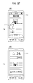
- Figs. 25 to 27 are views illustrating operations of a lock screen area of the mobile terminal shown in Fig. 1 ;
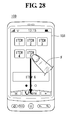
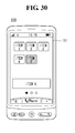
- Figs. 28 to 30 are views illustrating operations of a hidden area of the mobile terminal shown in Fig. 1 .
- the mobile terminal described in the specification can include a cellular phone, a smart phone, a laptop computer, a digital broadcasting terminal, personal digital assistants (PDA), a portable multimedia player (PMP), a navigation system and so on.
- PDA personal digital assistants
- PMP portable multimedia player
- Fig. 1 is a block diagram of a mobile terminal 100 according to an embodiment of the present invention. Other embodiments, configurations and arrangements may also be provided. As shown, the mobile terminal 100 may include a radio communication unit 110, an audio/video (A/V) input unit 120, a user input unit 130, a sensing unit 140, an output unit 150, a memory 160, an interface 170, a controller 180, and a power supply 190. Not all of the components shown in Fig. 1 may be essential parts and the number of components included in the mobile terminal 100 may be varied. The components of the mobile terminal 100 will now be described.
- A/V audio/video
- the radio communication unit 110 may include at least one module that enables radio communication between the mobile terminal 100 and a radio communication system or between the mobile terminal 100 and a network in which the mobile terminal 100 is located.
- the radio communication unit 110 may include a broadcasting receiving module 111, a mobile communication module 112, a wireless Internet module 113, a local area communication module 114, and a location (or position) information module 115.
- the broadcasting receiving module 111 may receive broadcasting signals and/or broadcasting related information from an external broadcasting management server through a broadcasting channel.
- the broadcasting channel may include a satellite channel and a terrestrial channel
- the broadcasting management server may be a server that generates and transmits broadcasting signals and/or broadcasting related information or a server that receives previously created broadcasting signals and/or broadcasting related information and transmits the broadcasting signals and/or broadcasting related information to a terminal.
- the broadcasting signals may include not only TV broadcasting signals, radio broadcasting signals, and data broadcasting signals but also signals in the form of a combination of a TV broadcasting signal and a radio broadcasting signal.
- the broadcasting related information may be information on a broadcasting channel, a broadcasting program or a broadcasting service provider, and may be provided even through a mobile communication network. In the latter case, the broadcasting related information may be received by the mobile communication module 112.
- the broadcasting related information may exist in various forms.
- the broadcasting related information may exist in the form of an electronic program guide (EPG) of a digital multimedia broadcasting (DMB) system or in the form of an electronic service guide (ESG) of a digital video broadcast-handheld (DVB-H) system.
- EPG electronic program guide
- ESG electronic service guide
- DMB digital multimedia broadcasting
- DVB-H digital video broadcast-handheld
- the broadcasting receiving module 111 may receive broadcasting signals using various broadcasting systems. More particularly, the broadcasting receiving module 111 may receive digital broadcasting signals using digital broadcasting systems such as a digital multimedia broadcasting-terrestrial (DMB-T) system, a digital multimedia broadcasting-satellite (DMB-S) system, a media forward link only (MediaFLO) system, a DVB-H and integrated services digital broadcast-terrestrial (ISDB-T) systems.
- DMB-T digital multimedia broadcasting-terrestrial
- DMB-S digital multimedia broadcasting-satellite
- MediaFLO media forward link only
- ISDB-T integrated services digital broadcast-terrestrial
- the broadcasting receiving module 111 may receive signals from broadcasting systems providing broadcasting signals other than the above-described digital broadcasting systems.
- the broadcasting signals and/or broadcasting related information received through the broadcasting receiving module 111 may be stored in the memory 160.
- the mobile communication module 112 may transmit/receive a radio signal to/from at least one of a base station, an external terminal and a server on a mobile communication network.
- the radio signal may include a voice call signal, a video telephony call signal or data in various forms according to transmission and reception of text/multimedia messages.
- the wireless Internet module 113 may correspond to a module for wireless Internet access and may be included in the mobile terminal 100 or may be externally attached to the mobile terminal 100.
- Wireless LAN WLAN or Wi-Fi
- Wibro wireless broadband
- Wimax world interoperability for microwave access
- HSDPA high speed downlink packet access
- the local area communication module 114 may correspond to a module for local area communication. Further, Bluetooth®, radio frequency identification (RFID), infrared data association (lrDA), ultra wideband (UWB) and/or ZigBee® may be used as a local area communication technique.
- RFID radio frequency identification
- lrDA infrared data association
- UWB ultra wideband
- ZigBee® ZigBee®
- the location information module 115 may confirm or obtain the position of the mobile terminal 100.
- the position information module 115 may obtain position information by using a global navigation satellite system (GNSS).
- GNSS is a terminology describing a radio navigation satellite system that revolves around the earth and transmits reference signals to predetermined types of radio navigation receivers such that the radio navigation receivers can determine their positions on the earth's surface or near the earth's surface.
- the GNSS may include a global positioning system (GPS) of the United States, Galileo of Europe, a global orbiting navigational satellite system (GLONASS) of Russia, COMPASS of China, and a quasi-zenith satellite system (QZSS) of Japan among others.
- GPS global positioning system
- Galileo Galileo of Europe
- GLONASS global orbiting navigational satellite system
- QZSS quasi-zenith satellite system
- a global positioning system (GPS) module is a representative example of the location information module 115.
- the GPS module 115 may calculate information on distances between one point or object and at least three satellites and information on a time when the distance information is measured and apply trigonometry to the obtained distance information to obtain three-dimensional position information on the point or object according to latitude, longitude and altitude at a predetermined time.
- a method of calculating position and time information using three satellites and correcting the calculated position and time information using another satellite may also be used.
- the GPS module 115 may continuously calculate the current position in real time and calculate velocity information using the location or position information.
- the A/V input unit 120 may input an audio signal or a video signal and include a camera 121 and a microphone 122.
- the camera 121 may process image frames of still images or moving images obtained by an image sensor in a video telephony mode or a photographing mode.
- the processed image frames may be displayed on a display 151 which may be a touch screen.
- the image frames processed by the camera 121 may be stored in the memory 160 or may be transmitted to an external device through the radio communication unit 110.
- the mobile terminal 100 may also include at least two cameras 121.
- the microphone 122 may receive an external audio signal in a call mode, a recording mode or a speech recognition mode and process the received audio signal into electric audio data. The audio data may then be converted into a form that can be transmitted to a mobile communication base station through the mobile communication module 112 and output in the call mode.
- the microphone 122 may employ various noise removal algorithms (or noise canceling algorithm) for removing or reducing noise generated when the external audio signal is received.
- the user input unit 130 may receive input data for controlling operation of the mobile terminal 100 from a user.
- the user input unit 130 may include a keypad, a dome switch, a touch pad (constant voltage/capacitance), a jog wheel, a jog switch and so on.
- the sensing unit 140 may sense a current state of the mobile terminal 100, such as an open/close state of the mobile terminal 100, a position of the mobile terminal 100, whether a user touches the mobile terminal 100, a direction of the mobile terminal 100, and acceleration/deceleration of the mobile terminal 100, and generate a sensing signal for controlling operation of the mobile terminal 100.
- a current state of the mobile terminal 100 such as an open/close state of the mobile terminal 100, a position of the mobile terminal 100, whether a user touches the mobile terminal 100, a direction of the mobile terminal 100, and acceleration/deceleration of the mobile terminal 100
- the sensing unit 140 may sense whether the slide phone is opened or closed. Further, the sensing unit 140 may sense whether the power supply 190 supplies power and/or whether the interface 170 is connected to an external device.
- the sensing unit 140 may also include a posture detection sensor 141.
- the output unit 150 may generate visual, auditory and/or tactile output and may include the display 151, an audio output module 152, an alarm 153 and a haptic module 154.
- the display 151 may display information processed by the mobile terminal 100.
- the display 151 may display a user interface (UI) or a graphic user interface (GUI) related to a telephone call when the mobile terminal 100 is in the call mode.
- the display 151 may also display a captured and/or received image, a UI or a GUI when the mobile terminal 100 is in the video telephony mode or the photographing mode.
- the display 151 may include at least one of a liquid crystal display, a thin film transistor liquid crystal display, an organic light-emitting diode display, a flexible display and a three-dimensional display. Some of these displays may be of a transparent type or a light transmissive type. That is, the display 151 may include a transparent display.
- the transparent display may include a transparent liquid crystal display.
- the rear structure of the display 151 may also be of a light transmissive type. Accordingly, a user may see an object located behind the body of the mobile terminal 100 through the transparent area of the body of the mobile terminal 100 that is occupied by the display 151.
- the mobile terminal 100 may also include at least two displays 151.
- the mobile terminal 100 may include a plurality of displays 151 that are arranged on a single face at a predetermined distance or integrated displays.
- the plurality of displays 151 may also be arranged on different sides.
- the display 151 and a sensor sensing touch form a layered structure that is referred to as a touch screen
- the display 151 may be used as an input device in addition to an output device.
- the touch sensor may be in the form of a touch film, a touch sheet, and a touch pad, for example.
- the touch sensor may convert a variation in pressure applied to a specific portion of the display 151 or a variation in capacitance generated at a specific portion of the display 151 into an electric input signal.
- the touch sensor may sense pressure of touch as well as position and area of the touch.
- a signal corresponding to the touch input may be transmitted to a touch controller.
- the touch controller may then process the signal and transmit data corresponding to the processed signal to the controller 180. Accordingly, the controller 180 may detect a touched portion of the display 151.
- the proximity sensor 141 of the sensing unit 140 may be located in an internal region of the mobile terminal 100, surrounded by the touch screen, or near the touch screen.
- the proximity sensor 141 may sense an object approaching a predetermined sensing face or an object located near the proximity sensor using an electromagnetic force or infrared rays without having mechanical contact.
- the proximity sensor 141 may have a lifetime longer than a contact sensor and may thus have a wide application in the mobile terminal 100.
- the proximity sensor 141 may include a transmission type photo-electric sensor, a direct reflection type photo-electric sensor, a mirror reflection type photo-electric sensor, a high-frequency oscillating proximity sensor, a capacitive proximity sensor, a magnetic proximity sensor, and/or an infrared proximity sensor.
- a capacitive touch screen may be constructed such that proximity of a pointer is detected through a variation in an electric field according to the proximity of the pointer.
- the touch screen (touch sensor) may be classified as a proximity sensor 141.
- an action of the pointer approaching the touch screen without actually touching the touch screen may be referred to as a proximity touch and an action of bringing the pointer into contact with the touch screen may be referred to as a contact touch.
- the proximity touch point of the pointer on the touch screen may correspond to a point of the touch screen at which the pointer is perpendicular to the touch screen.
- the proximity sensor 141 may sense the proximity touch and a proximity touch pattern (e.g., a proximity touch distance, a proximity touch direction, a proximity touch velocity, a proximity touch time, a proximity touch position, a proximity touch moving state, etc.). Information corresponding to the sensed proximity touch action and proximity touch pattern may then be displayed on the touch screen.
- a proximity touch pattern e.g., a proximity touch distance, a proximity touch direction, a proximity touch velocity, a proximity touch time, a proximity touch position, a proximity touch moving state, etc.
- the audio output module 152 may output audio data received from the radio communication unit 110 or stored in the memory 160 in a call signal receiving mode, a telephone call mode or a recording mode, a speech recognition mode and a broadcasting receiving mode.
- the audio output module 152 may output audio signals related to functions, such as a call signal incoming tone and a message incoming tone, performed in the mobile terminal 100.
- the audio output module 152 may include a receiver, a speaker, a buzzer, and the like.
- the audio output module 152 may output sounds through an earphone jack. The user may hear the sounds by connecting an earphone to the earphone jack.
- the alarm 153 may output a signal for indicating generation of an event of the mobile terminal 100. For example, alarms may be generated when receiving a call signal, receiving a message, inputting a key signal, or inputting touch.
- the alarm 153 may also output signals in forms different from video signals or audio signals, for example, a signal for indicating generation of an event through vibration.
- the video signals or the audio signals may also be output through the display 151 or the audio output module 152.
- the haptic module 154 may generate various haptic effects that the user can feel.
- One example of the haptic effects is vibration.
- the intensity and/or pattern of vibration generated by the haptic module 154 may also be controlled. For example, different vibrations may be combined and output or may be sequentially output.
- the haptic module 154 may generate a variety of haptic effects including an effect of stimulus according to an arrangement of pins vertically moving against a contact skin surface, an effect of stimulus according to a jet force or sucking force of air through a jet hole or a sucking hole, an effect of stimulus of rubbing the skin, an effect of stimulus according to contact of an electrode, an effect of stimulus using an electrostatic force, and an effect according to a reproduction of cold and warmth using an element capable of absorbing or radiating heat in addition to vibrations.
- the haptic module 154 may not only transmit haptic effects through direct contact but may also allow the user to feel haptic effects through a kinesthetic sense of the user's fingers or arms.
- the mobile terminal 100 may also include a plurality of haptic modules 154.
- the memory 160 may store a program for operation of the controller 180 and temporarily store input/output data such as a phone book, messages, still images, and/or moving images.
- the memory 160 may also store data about vibrations and sounds in various patterns that are output from when a touch input is applied to the touch screen.
- the memory 160 may include at least a flash memory, a hard disk type memory, a multimedia card micro type memory, a card type memory, such as SD or XD memory, a random access memory (RAM), a static RAM (SRAM), a read-only memory (ROM), an electrically erasable programmable ROM (EEPROM), a programmable ROM (PROM) magnetic memory, a magnetic disk or an optical disk.
- the mobile terminal 100 may also operate in relation to a web storage performing the storing function of the memory 160 on the Internet.
- the interface 170 may serve as a path to external devices connected to the mobile terminal 100.
- the interface 170 may receive data from the external devices or power and transmit the data or power to internal components of the mobile terminal 100 or transmit data of the mobile terminal 100 to the external devices.
- the interface 170 may include a wired/wireless headset port, an external charger port, a wired/wireless data port, a memory card port, a port for connecting a device having a user identification module, an audio I/O port, a video I/O port, and/or an earphone port.
- the interface 170 may also interface with a user identification module that is a chip that stores information for authenticating authority to use the mobile terminal 100.
- the user identification module may be a user identify module (UIM), a subscriber identify module (SIM) and a universal subscriber identify module (USIM).
- An identification device including the user identification module may also be manufactured in the form of a smart card. Accordingly, the identification device may be connected to the mobile terminal 100 through a port of the interface 170.
- the interface 170 may also be a path through which power from an external cradle is provided to the mobile terminal 100 when the mobile terminal 100 is connected to the external cradle or a path through which various command signals input by the user through the cradle are transmitted to the mobile terminal 100.
- the various command signals or power input from the cradle may be used as signals for confirming whether the mobile terminal 100 is correctly set in the cradle.
- the controller 180 may control overall operations of the mobile terminal 100.
- the controller 180 may perform control and processing for voice communication, data communication and/or video telephony.
- the controller 180 may also include a multimedia module 181 for playing multimedia.
- the multimedia module 181 may be included in the controller 180 as shown in Fig. 1 or may be separated from the controller 180.
- the controller 180 may perform a pattern recognition process capable of recognizing handwriting input or picture-drawing input applied to the touch screen as characters or images.
- the power supply 190 may receive external power and internal power and provide power required for operations of the components of the mobile terminal 100 under control of the controller 180.
- embodiments of the present disclosure may be implemented using at least one of application specific integrated circuits (ASICs), digital signal processors (DSPs), digital signal processing devices (DSPDs), programmable logic devices (PLDs), field programmable gate arrays (FPGAs), processors, controllers, micro-controllers, microprocessors, and/or electrical units for executing functions.
- ASICs application specific integrated circuits
- DSPs digital signal processors
- DSPDs digital signal processing devices
- PLDs programmable logic devices
- FPGAs field programmable gate arrays
- processors controllers, micro-controllers, microprocessors, and/or electrical units for executing functions.
- controller 180 may be implemented by the controller 180.
- embodiments such as procedures or functions may be implemented with a separate software module executing at least one function or operation.
- Software codes may be implemented according to a software application written in an appropriate software language. The software codes may be stored in the memory 160 and executed by the controller 180.
- Fig. 2 is a flowchart illustrating an operation of the mobile terminal shown in Fig. 1 .
- the controller 180 of the mobile terminal 100 may perform a step of initiating an editing mode (S10).
- the editing mode may refer to a state in which a user of the mobile terminal 100 may use a virtual area according to an embodiment.
- general functions are configured to be performed before the editing mode, while under the editing mode unique functions for the editing mode are configured to be performed.
- a virtual area set when the editing mode is activated will be specifically described in relevant part below.
- the controller 180 in the editing mode, may set at least one area having a different attribute from an attribute of a current display screen at a periphery of the display screen.
- the set area may be divided into a plurality of sub areas which have different attributes from each other. Unless otherwise stated, the set area is referred to as a "virtual area".
- the virtual area may be located at, at least, one of upper, lower, left, and right sides of the current screen. Accordingly, it may be needed to obtain not only a touch operation of selecting a specific item but also a direction of a touch stroke included in the touch operation.
- a step S50 may be performed to move a selected item to an area corresponding to the obtained direction of the touch input.
- the item may be selected upon a user's entry of a touch down operation. For example, when an upper portion of an item displayed at a specific location, the touch item may be selected.
- the user may perform an operation of dragging the item along a specific direction. For example, after selecting an item located at a center of the screen by a touch down operation, a user may drag the item to an upper portion of the display 151.
- the controller 180 may determine that the user intended to move the item into the virtual area located at the upper portion. For example, in the case that a buffer area exists at the upper portion of the display 151, the controller 180 may determine that there was a touch operation of moving the selected item into the buffer area.
- a function depending on an attribute of the area may be performed (S60).
- the moved area may be any one of virtual areas outside a display area of the display 151.
- the virtual areas may have different attributes from an attribute of the current display area. Further, the virtual areas may have different attributes from each other.
- the controller 180 may perform a function corresponding to an attribute of a virtual area into which the item has been moved. For example, when the item is moved into a buffer area, the controller 180 may perform an operation of temporarily storing the item until a subsequent operation is entered.
- Figs. 3A and 3B illustrate an example of initiating an editing mode as described in connection with Fig. 2 .
- the controller 180 of the mobile terminal 100 may perform an editing mode that may operate a function associated with a virtual area upon a predetermined entry.
- the display 151 may display various items.
- the items may be icons.
- the icons may correspond to predetermined applications, respectively. For example, when a certain icon is selected, an application corresponding to the selected icon may be performed.
- the items may be widgets.
- the items may be icons that may display states of the mobile terminal 100 and/or obtained data. For example, when messages are received, the number of the messages may be displayed on a widget.
- the items may be contents.
- Each item may be an image file, a video file, and a sound file.
- an item when a user selects the item, the image may be displayed on the entire screen of the display 151.
- a user may perform a long touch on a predetermined point on the display 151 using his finger F.
- the controller 180 may initiate the editing mode. For example, it may be preset that when keeping a touch on a space without the items for a predetermined time, the editing mode is initiated.
- Fig. 4 is a view illustrating an exemplary virtual area of the mobile terminal shown in Fig. 1 .
- the controller 180 of the mobile terminal 100 may set virtual areas surrounding a current screen area O.
- the current screen area O may be an area that is displayed on the display 151 until entry into an editing mode.
- the current screen area O may display contents that have been displayed upon entry of the editing mode.
- the controller 180 may display virtual areas surrounding the current screen area O.
- the virtual areas include a buffer area B, a management area M, a lock screen area L, and a hidden area H.
- the buffer area B, the management area M, the lock screen area L, and the hidden area H may be respectively positioned at an upper portion, a left portion, a right portion, and a lower portion of the current screen area O.
- the virtual areas may be conceptually positioned at those locations. For example, simultaneously with entry into the editing mode, the virtual areas may not be displayed on the display 151.
- the screen changes to display the virtual areas including the buffer area B on the display 151 while keeping the screen displayed as is. For example, despite the entry into the editing mode, the buffer area B, the management area M, the lock screen area L, and the hidden area H may not be explicitly displayed on the display 151.
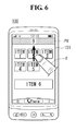
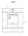
- Figs. 5 to 7 are views illustrating examples of using virtual areas of the mobile terminal as shown in Fig. 1 .
- the controller 180 of the mobile terminal 100 may perform an operation of moving a specific item into a virtual area in response to a user's touch input.
- a user may select a specific item using his finger F.
- the user may form a touch trajectory TF in a certain direction. For example, a touch operation of dragging the selected item upward may be performed.
- the controller 180 may expose part of a virtual area positioned along the direction to the user. For example, when the user's touch approaches the upper border, part of a preview area PV may be exposed. When the preview area PV is displayed, the user may visually identify, in advance, what attribute the virtual area corresponding to the dragged direction has. Accordingly, an unwanted virtual area may be previously prevented from being operated due to errors or malfunctions.
- the item selected and moved by the user may be located in a corresponding virtual area.
- the controller 180 may move ITEM 5 selected by the user's touch operation from the current screen area to the buffer area B and display ITEM5 on the buffer area B.
- the controller 180 may relocate ITEM6 in the buffer area B and may display part or whole of a virtual area including the buffer area B on the display 151. For example, it can be visually displayed in which virtual area an item is relocated.
- Fig. 8 is a view illustrating another example of initiating an editing mode by the mobile terminal as shown in Fig. 1 .
- the controller 180 of the mobile terminal 100 may initiate an editing mode upon a user's specific touch operation.
- the user may touch the display 151 using his first and second fingers F1 and F2.
- the touch operation using the first and second fingers F1 and F2 may include a touch that has the first and second fingers F1 and F2 close to each other.
- the controller 180 may initiate an editing mode.
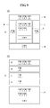
- Figs. 9 to 11 are views illustrating various exemplary virtual areas of the mobile terminal shown in Fig. 1 .
- the controller 180 of the mobile terminal 100 may set virtual areas by various methods.
- virtual areas may be located surrounding a current screen area O.
- virtual areas may be stacked over a current screen area O.
- the current screen area O is located at a lowermost part, and a hidden area H, a lock screen area L, a management area M, and a buffer area B may be sequentially set over the current screen area O.
- the controller 180 may selectively display the virtual areas. For example, while displaying the current screen area O under the current circumstance, the controller 180 may sequentially display the virtual areas.
- a virtual area may be set to be located only over a current screen area O.
- a first virtual area A1 may be set to be located over and adjacent to the current screen area O.
- virtual areas may be respectively set to be located under and over a current screen area O.
- first and second virtual areas A1 and A2 may be respectively set to be located over and under the current screen area O and adjacent to the current screen area O.
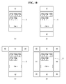
- virtual areas may be set to be located over diagonal lines extending from a current screen area O.
- third and fourth virtual areas A3 and A4 may be set to be located over diagonal lines extending from the current screen area O.
- the third and fourth virtual areas A3 and A4 may be positioned at left and right sides of the first virtual area A1.
- virtual areas may be set to be located adjacent to and surrounding a current screen area O.
- first to eighth virtual areas A1 to A8 may be set to be located adjacent to the current screen area O.
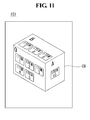
- virtual areas may be set to be located in a shape of a cube CB.
- virtual areas may be set to be located on respective corresponding surfaces of the cube CB or located on some surfaces of the cube CB.
- the controller 180 may rotate the cube CB.
- a user may rotate the cube CB so that a desired surface is displayed. Further, the user may relocate an item from a surface of the cube CB to another surface of the cube CB.
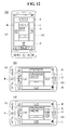
- Figs. 12A and 12B are views illustrating arrangements of virtual areas as the mobile terminal shown in Fig. 1 rotates.
- the controller 180 of the mobile terminal 100 may adjust the locations of the virtual areas depending on a rotational direction of the mobile terminal 100.
- the controller 180 may respectively set a buffer area, a hidden area H, a lock screen area L, and a management area M at an upper side, a lower side, a right side, and a left side of a current screen area O.
- the arrangement of the virtual areas may be pre-set or properly adjusted by a user.
- the controller 180 may maintain the locations of the virtual areas when the mobile terminal 100 stays upright. For example, irrespective of the rotation of the mobile terminal 100, the virtual areas may be positioned at predetermined locations, respectively.
- the controller 180 may rotate the locations of the virtual areas to correspond to the direction of the rotation of the100. For example, when the mobile terminal 100 rotates clockwise, the virtual areas may also rotate sequentially clockwise.
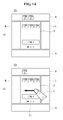
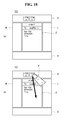
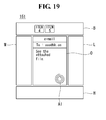
- Figs. 13 to 19 are views illustrating operations of buffer areas of the mobile terminal shown in Fig. 1 .
- the controller 180 of the mobile terminal 100 may perform an operation corresponding to a user's touch on a set buffer area B.
- the display 151 may display a current screen area O and virtual areas B, L, H, and M.
- the virtual areas B, L, H, and M may be displayed on the display 151 together with the current screen area O.
- some of the virtual areas B, L, H, and M may be displayed together with the current screen area O or only certain parts of the virtual areas B, L, H, and M may be displayed.
- a user may perform a touch operation of touching a specific item using his finger F and dragging the item into the buffer area B.
- the user may drag a plurality of items one by one or may select and drag the plurality of items at once.
- the moved items may be located in the buffer area B.
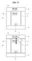
- the user may perform a touch operation of dragging a current screen area O in a left direction.
- the touch operation of dragging the current screen area O in the left direction may correspond to a function of shifting the current screen area O to another background screen.
- a background screen of another page may be displayed on a current screen area O of the display 151. This may be intuitively recognized by a page indicator PI indicating at what position the background screen being currently displayed is located among a plurality of background screens.
- a user may select a desired item of items relocated in the buffer area B and drag the selected item into the current screen area O.
- the item dragged by the user may be relocated in the current screen area O and displayed.
- Applying a method of temporarily moving an item in the buffer area and then relocating into a desired page may reduce a chance of malfunction and increase convenience in manipulation compared to the prior art of moving items one by one.
- another item may be dragged to overlap the item located in the buffer area B.
- a user may perform a touch operation of dragging and dropping ITEM5 on ITEM4 located in the buffer area B.
- the overlapping items may generate a group or a folder.
- the name of the generated group may vary with attributes of the overlapping items.
- items selected and relocated by a user may be positioned in the buffer area B.
- An email application may be executed in the current screen area O.
- a user may perform a touch operation of selecting a specific item among items in the buffer area B and dragging and dropping the selected item in the current screen area O.
- the item when the user selects the specific item and drags and drops the selected item in the current screen area, the item may become an attached file Al for an email.
- the application executed in the current screen area O may be a picture view application, so that when an item in the buffer area B is dragged and dropped in the current screen area O, the item may be viewed by the picture view application.
- the application executed in the current screen area O may be an mp3 player application, so that when an item in the buffer area B is dragged and dropped in the current screen area O, the item may be played by the mp3 player application.
- an operation associated with a specific application may be performed thus providing convenience of manipulation, such as attaching files.
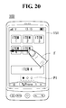
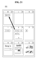
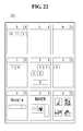
- Figs. 20 to 24 are view illustrating operation of a management area of the mobile terminal shown in Fig. 1 .
- the controller 180 of the mobile terminal 100 may effectively manage, for example, background screens through the management area M.
- a user may perform a drag touch operation of selecting a specific item and moving the selected item leftward.
- the controller 180 may display the management area M on the display 151.
- the management area M may be an area for displaying each background screen and/or each application in execution of the mobile terminal 100.
- Each background screen and/or each application in execution may be displayed in the shape of panels.
- the management area M may display a current state of the virtual areas. For example, the management area M may display what items are located in the buffer area B, lock screen area L, and hidden area H.
- the management area M may display states of background screens as set, such as background screens 1 to 3. For example, the management area M may display that items 7 and 8 are located in the background 1.
- the management area M may display current states of applications in execution, such as applications 4 to 6.
- the management area M may display that the applications 4 and 5 in execution are web surfing applications and the application 6 in execution is a picture view application.
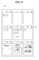
- a user may relocate an item from a specific location to another location in the management area M.
- the user may move the item 1 from the background screen 2 into the buffer area B by a drag and drop touch operation.
- each panel in the management area M may display a delete button CI.
- a panel may be deleted by a user selecting the corresponding delete button CI.
- the background screen 3 may be deleted.
- the user may delete not only each panel but also each item. For example, by the user performing a long touch on a specific item, the item may be deleted or a menu for deleting the item may be popped up.
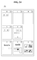
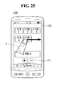
- Figs. 25 to 27 are views illustrating operations of a lock screen area of the mobile terminal shown in Fig. 1 .
- the controller 180 of the mobile terminal 100 may select items to be displayed on a lock screen through the lock screen area L.
- a user may perform an operation of selecting a specific item and dragging the selected item rightwards.
- an item ITEM5 selected by the user may be arranged on the display 151.
- the controller 180 may enable the item ITEM5 to be executed immediately when the user selects the item ITEM5 irrespective of whether the mobile terminal 100 is locked. For example, a process of selecting the item ITEM5 after the mobile terminal is unlocked may be omitted.
- a specific application may be in execution.
- an application for web surfing may be executed. While the application is in execution, a user may relocate the application into a lock screen area L by performing a touch operation of dragging the application in the right direction of the display 151 using his finger F.
- the application relocated in the lock screen may be displayed as a background screen of the lock screen.
- the application may be executed.
- Figs. 28 to 30 are views illustrating operations of a hidden area of the mobile terminal shown in Fig. 1 .
- the controller 180 of the mobile terminal 100 may perform a touch operation of selecting a specific item and dragging the selected item in a hidden area H which is located at a lower portion of the display 151, and may restrict access to the specific item.
- a password may need to be entered to enter into the hidden area H, and only when a right password is entered, the hidden area H may be allowed to access.
- the items in the hidden area H may be displayed.
- the controller 180 may restrict access to a specific item relocated in the hidden area. For example, to visually express that the specific item relocated in the hidden area has been inactivated, the controller 180 may add hatching to ITEM5. According to an embodiment, the controller 180 may delete the specific item relocated in the hidden area from the display 151.
- the above-described method of controlling the mobile terminal may be written as computer programs and may be implemented in digital microprocessors that execute the programs using a computer readable recording medium.
- the method of controlling the mobile terminal may be executed through software.
- the software may include code segments that perform required tasks. Programs or code segments may also be stored in a processor readable medium or may be transmitted according to a computer data signal combined with a carrier through a transmission medium or communication network.
- the computer readable recording medium may be any data storage device that can store data that can be thereafter read by a computer system. Examples of the computer readable recording medium may include read-only memory (ROM), random-access memory (RAM), CD-ROMs, DVD ⁇ ROM, DVD-RAM, magnetic tapes, floppy disks, optical data storage devices.
- ROM read-only memory
- RAM random-access memory
- CD-ROMs CD-ROMs
- DVD ⁇ ROM DVD-RAM
- magnetic tapes floppy disks
- optical data storage devices optical data storage devices.
- the computer readable recording medium may also be distributed over network coupled computer systems so that the computer readable code is stored and executed in a distribution fashion.
- a mobile terminal may include a first touch screen configured to display a first object, a second touch screen configured to display a second object, and a controller configured to receive a first touch input applied to the first object and to link the first object to a function corresponding to the second object when receiving a second touch input applied to the second object while the first touch input is maintained.
- a method may be provided of controlling a mobile terminal that includes displaying a first object on the first touch screen, displaying a second object on the second touch screen, receiving a first touch input applied to the first object, and linking the first object to a function corresponding to the second object when a second touch input applied to the second object is received while the first touch input is maintained.
- any reference in this specification to "one embodiment,” “an embodiment,” “example embodiment,” etc. means that a particular feature, structure, or characteristic described in connection with the embodiment is included in at least one embodiment of the invention.
- the appearances of such phrases in various places in the specification are not necessarily all referring to the same embodiment.
Abstract
Description
- This application claims the benefit of earlier filing date and right of priority to Korean Patent Application No.
10-2011-0092733, filed on Sep 15, 2011 - The embodiments of the present invention are directed to a mobile terminal and a method of controlling the mobile terminal, and more specifically to a mobile terminal and a method of controlling the mobile terminal, which can set a virtual area adjacent to a display area and control an item selected according to an attribute of the virtual area.
- As functions of terminals such as personal computers, laptop computers, cellular phones diversify, the terminals become multimedia players having multiple functions for capturing pictures or moving images, playing music, moving image files and games and receiving broadcasting programs.
- Terminals can be categorized as mobile terminals and stationary terminals. The mobile terminals can be further comprised of handheld terminals and vehicle mount terminals according to whether users can personally carry the terminals. Conventional terminals including mobile terminals provide an increasing number of complex and various functions.
- To support and enhance the increasing number of functions in a terminal, improving a structural part and/or a software part of the terminal would be desirable.
- The embodiments of the present invention are directed to a mobile terminal and a method of controlling the mobile terminal, and more specifically to a mobile terminal and a method of controlling the mobile terminal, which can set a virtual area adjacent to a display area and control an item selected according to an attribute of the virtual area.
- The accompanying drawings, which are included to provide a further understanding of the invention and are incorporated in and constitute a part of this application, illustrate embodiment(s) of the invention and together with the description serve to explain the principle of the invention.
-
Fig. 1 is a block diagram of a mobile terminal according to an embodiment of the present invention; -
Fig. 2 is a flowchart illustrating an operation of the mobile terminal shown inFig. 1 ; -
Figs. 3A and 3B illustrate an example of initiating an editing mode as described in connection withFig. 2 ; -
Fig. 4 is a view illustrating an exemplary virtual area of the mobile terminal shown inFig. 1 ; -
Figs. 5 to 7 are views illustrating examples of using virtual areas of the mobile terminal as shown inFig. 1 ; -
Fig. 8 is a view illustrating another example of initiating an editing mode by the mobile terminal as shown inFig. 1 ; -
Figs. 9 to 11 are views illustrating various exemplary virtual areas of the mobile terminal shown inFig. 1 ; -
Figs. 12A and 12B are views illustrating arrangements of virtual areas as the mobile terminal shown inFig. 1 rotates -
Figs. 13 to 19 are views illustrating operations of buffer areas of the mobile terminal shown inFig. 1 ; -
Figs. 20 to 24 are view illustrating operation of a management area of the mobile terminal shown inFig. 1 ; -
Figs. 25 to 27 are views illustrating operations of a lock screen area of the mobile terminal shown inFig. 1 ; and -
Figs. 28 to 30 are views illustrating operations of a hidden area of the mobile terminal shown inFig. 1 . - The present invention will now be described more fully with reference to the accompanying drawings, in which exemplary embodiments of the invention are shown. The invention may, however, be embodied in many different forms and should not be construed as being limited to the embodiments set forth herein; rather, there embodiments are provided so that this disclosure will be thorough and complete, and will fully convey the concept of the invention to those skilled in the art.
- Hereinafter, a mobile terminal relating to the present invention will be described below in more detail with reference to the accompanying drawings. In the following description, suffixes "module" and "unit" are given to components of the mobile terminal in consideration of only facilitation of description and do not have meanings or functions discriminated from each other.
- The mobile terminal described in the specification can include a cellular phone, a smart phone, a laptop computer, a digital broadcasting terminal, personal digital assistants (PDA), a portable multimedia player (PMP), a navigation system and so on.
-
Fig. 1 is a block diagram of amobile terminal 100 according to an embodiment of the present invention. Other embodiments, configurations and arrangements may also be provided. As shown, themobile terminal 100 may include aradio communication unit 110, an audio/video (A/V)input unit 120, auser input unit 130, asensing unit 140, anoutput unit 150, amemory 160, aninterface 170, acontroller 180, and apower supply 190. Not all of the components shown inFig. 1 may be essential parts and the number of components included in themobile terminal 100 may be varied. The components of themobile terminal 100 will now be described. - The
radio communication unit 110 may include at least one module that enables radio communication between themobile terminal 100 and a radio communication system or between themobile terminal 100 and a network in which themobile terminal 100 is located. For example, theradio communication unit 110 may include abroadcasting receiving module 111, amobile communication module 112, awireless Internet module 113, a localarea communication module 114, and a location (or position)information module 115. - The broadcasting receiving
module 111 may receive broadcasting signals and/or broadcasting related information from an external broadcasting management server through a broadcasting channel. The broadcasting channel may include a satellite channel and a terrestrial channel, and the broadcasting management server may be a server that generates and transmits broadcasting signals and/or broadcasting related information or a server that receives previously created broadcasting signals and/or broadcasting related information and transmits the broadcasting signals and/or broadcasting related information to a terminal. - The broadcasting signals may include not only TV broadcasting signals, radio broadcasting signals, and data broadcasting signals but also signals in the form of a combination of a TV broadcasting signal and a radio broadcasting signal. The broadcasting related information may be information on a broadcasting channel, a broadcasting program or a broadcasting service provider, and may be provided even through a mobile communication network. In the latter case, the broadcasting related information may be received by the
mobile communication module 112. - The broadcasting related information may exist in various forms. For example, the broadcasting related information may exist in the form of an electronic program guide (EPG) of a digital multimedia broadcasting (DMB) system or in the form of an electronic service guide (ESG) of a digital video broadcast-handheld (DVB-H) system.
- The broadcasting receiving
module 111 may receive broadcasting signals using various broadcasting systems. More particularly, the broadcasting receivingmodule 111 may receive digital broadcasting signals using digital broadcasting systems such as a digital multimedia broadcasting-terrestrial (DMB-T) system, a digital multimedia broadcasting-satellite (DMB-S) system, a media forward link only (MediaFLO) system, a DVB-H and integrated services digital broadcast-terrestrial (ISDB-T) systems. The broadcasting receivingmodule 111 may receive signals from broadcasting systems providing broadcasting signals other than the above-described digital broadcasting systems. - The broadcasting signals and/or broadcasting related information received through the broadcasting receiving
module 111 may be stored in thememory 160. Themobile communication module 112 may transmit/receive a radio signal to/from at least one of a base station, an external terminal and a server on a mobile communication network. The radio signal may include a voice call signal, a video telephony call signal or data in various forms according to transmission and reception of text/multimedia messages. - The
wireless Internet module 113 may correspond to a module for wireless Internet access and may be included in themobile terminal 100 or may be externally attached to themobile terminal 100. Wireless LAN (WLAN or Wi-Fi), wireless broadband (Wibro), world interoperability for microwave access (Wimax), high speed downlink packet access (HSDPA) and so on may be used as a wireless Internet technique. - The local
area communication module 114 may correspond to a module for local area communication. Further, Bluetooth®, radio frequency identification (RFID), infrared data association (lrDA), ultra wideband (UWB) and/or ZigBee® may be used as a local area communication technique. - The
location information module 115 may confirm or obtain the position of themobile terminal 100. Theposition information module 115 may obtain position information by using a global navigation satellite system (GNSS). The GNSS is a terminology describing a radio navigation satellite system that revolves around the earth and transmits reference signals to predetermined types of radio navigation receivers such that the radio navigation receivers can determine their positions on the earth's surface or near the earth's surface. The GNSS may include a global positioning system (GPS) of the United States, Galileo of Europe, a global orbiting navigational satellite system (GLONASS) of Russia, COMPASS of China, and a quasi-zenith satellite system (QZSS) of Japan among others. - A global positioning system (GPS) module is a representative example of the
location information module 115. TheGPS module 115 may calculate information on distances between one point or object and at least three satellites and information on a time when the distance information is measured and apply trigonometry to the obtained distance information to obtain three-dimensional position information on the point or object according to latitude, longitude and altitude at a predetermined time. - A method of calculating position and time information using three satellites and correcting the calculated position and time information using another satellite may also be used. In addition, the
GPS module 115 may continuously calculate the current position in real time and calculate velocity information using the location or position information. - As shown in
Fig. 1 , the A/V input unit 120 may input an audio signal or a video signal and include acamera 121 and amicrophone 122. Thecamera 121 may process image frames of still images or moving images obtained by an image sensor in a video telephony mode or a photographing mode. The processed image frames may be displayed on adisplay 151 which may be a touch screen. - The image frames processed by the
camera 121 may be stored in thememory 160 or may be transmitted to an external device through theradio communication unit 110. Themobile terminal 100 may also include at least twocameras 121. - The
microphone 122 may receive an external audio signal in a call mode, a recording mode or a speech recognition mode and process the received audio signal into electric audio data. The audio data may then be converted into a form that can be transmitted to a mobile communication base station through themobile communication module 112 and output in the call mode. Themicrophone 122 may employ various noise removal algorithms (or noise canceling algorithm) for removing or reducing noise generated when the external audio signal is received. - The
user input unit 130 may receive input data for controlling operation of the mobile terminal 100 from a user. Theuser input unit 130 may include a keypad, a dome switch, a touch pad (constant voltage/capacitance), a jog wheel, a jog switch and so on. - The
sensing unit 140 may sense a current state of themobile terminal 100, such as an open/close state of themobile terminal 100, a position of themobile terminal 100, whether a user touches themobile terminal 100, a direction of themobile terminal 100, and acceleration/deceleration of themobile terminal 100, and generate a sensing signal for controlling operation of themobile terminal 100. For example, in case of a slide phone, thesensing unit 140 may sense whether the slide phone is opened or closed. Further, thesensing unit 140 may sense whether thepower supply 190 supplies power and/or whether theinterface 170 is connected to an external device. Thesensing unit 140 may also include aposture detection sensor 141. - The
output unit 150 may generate visual, auditory and/or tactile output and may include thedisplay 151, anaudio output module 152, analarm 153 and ahaptic module 154. Thedisplay 151 may display information processed by themobile terminal 100. Thedisplay 151 may display a user interface (UI) or a graphic user interface (GUI) related to a telephone call when themobile terminal 100 is in the call mode. Thedisplay 151 may also display a captured and/or received image, a UI or a GUI when themobile terminal 100 is in the video telephony mode or the photographing mode. - In addition, the
display 151 may include at least one of a liquid crystal display, a thin film transistor liquid crystal display, an organic light-emitting diode display, a flexible display and a three-dimensional display. Some of these displays may be of a transparent type or a light transmissive type. That is, thedisplay 151 may include a transparent display. - The transparent display may include a transparent liquid crystal display. The rear structure of the
display 151 may also be of a light transmissive type. Accordingly, a user may see an object located behind the body of themobile terminal 100 through the transparent area of the body of themobile terminal 100 that is occupied by thedisplay 151. - ]The
mobile terminal 100 may also include at least twodisplays 151. For example, themobile terminal 100 may include a plurality ofdisplays 151 that are arranged on a single face at a predetermined distance or integrated displays. The plurality ofdisplays 151 may also be arranged on different sides. - Further, when the
display 151 and a sensor sensing touch (hereafter referred to as a touch sensor) form a layered structure that is referred to as a touch screen, thedisplay 151 may be used as an input device in addition to an output device. The touch sensor may be in the form of a touch film, a touch sheet, and a touch pad, for example. - The touch sensor may convert a variation in pressure applied to a specific portion of the
display 151 or a variation in capacitance generated at a specific portion of thedisplay 151 into an electric input signal. The touch sensor may sense pressure of touch as well as position and area of the touch. - When the user applies a touch input to the touch sensor, a signal corresponding to the touch input may be transmitted to a touch controller. The touch controller may then process the signal and transmit data corresponding to the processed signal to the
controller 180. Accordingly, thecontroller 180 may detect a touched portion of thedisplay 151. - The
proximity sensor 141 of thesensing unit 140 may be located in an internal region of themobile terminal 100, surrounded by the touch screen, or near the touch screen. Theproximity sensor 141 may sense an object approaching a predetermined sensing face or an object located near the proximity sensor using an electromagnetic force or infrared rays without having mechanical contact. Theproximity sensor 141 may have a lifetime longer than a contact sensor and may thus have a wide application in themobile terminal 100. - The
proximity sensor 141 may include a transmission type photo-electric sensor, a direct reflection type photo-electric sensor, a mirror reflection type photo-electric sensor, a high-frequency oscillating proximity sensor, a capacitive proximity sensor, a magnetic proximity sensor, and/or an infrared proximity sensor. A capacitive touch screen may be constructed such that proximity of a pointer is detected through a variation in an electric field according to the proximity of the pointer. The touch screen (touch sensor) may be classified as aproximity sensor 141. - For ease of convenience of explanation, an action of the pointer approaching the touch screen without actually touching the touch screen may be referred to as a proximity touch and an action of bringing the pointer into contact with the touch screen may be referred to as a contact touch. The proximity touch point of the pointer on the touch screen may correspond to a point of the touch screen at which the pointer is perpendicular to the touch screen.
- The
proximity sensor 141 may sense the proximity touch and a proximity touch pattern (e.g., a proximity touch distance, a proximity touch direction, a proximity touch velocity, a proximity touch time, a proximity touch position, a proximity touch moving state, etc.). Information corresponding to the sensed proximity touch action and proximity touch pattern may then be displayed on the touch screen. - The
audio output module 152 may output audio data received from theradio communication unit 110 or stored in thememory 160 in a call signal receiving mode, a telephone call mode or a recording mode, a speech recognition mode and a broadcasting receiving mode. Theaudio output module 152 may output audio signals related to functions, such as a call signal incoming tone and a message incoming tone, performed in themobile terminal 100. Theaudio output module 152 may include a receiver, a speaker, a buzzer, and the like. Theaudio output module 152 may output sounds through an earphone jack. The user may hear the sounds by connecting an earphone to the earphone jack. - The
alarm 153 may output a signal for indicating generation of an event of themobile terminal 100. For example, alarms may be generated when receiving a call signal, receiving a message, inputting a key signal, or inputting touch. Thealarm 153 may also output signals in forms different from video signals or audio signals, for example, a signal for indicating generation of an event through vibration. The video signals or the audio signals may also be output through thedisplay 151 or theaudio output module 152. - The
haptic module 154 may generate various haptic effects that the user can feel. One example of the haptic effects is vibration. The intensity and/or pattern of vibration generated by thehaptic module 154 may also be controlled. For example, different vibrations may be combined and output or may be sequentially output. - The
haptic module 154 may generate a variety of haptic effects including an effect of stimulus according to an arrangement of pins vertically moving against a contact skin surface, an effect of stimulus according to a jet force or sucking force of air through a jet hole or a sucking hole, an effect of stimulus of rubbing the skin, an effect of stimulus according to contact of an electrode, an effect of stimulus using an electrostatic force, and an effect according to a reproduction of cold and warmth using an element capable of absorbing or radiating heat in addition to vibrations. - The
haptic module 154 may not only transmit haptic effects through direct contact but may also allow the user to feel haptic effects through a kinesthetic sense of the user's fingers or arms. Themobile terminal 100 may also include a plurality ofhaptic modules 154. - The
memory 160 may store a program for operation of thecontroller 180 and temporarily store input/output data such as a phone book, messages, still images, and/or moving images. Thememory 160 may also store data about vibrations and sounds in various patterns that are output from when a touch input is applied to the touch screen. - The
memory 160 may include at least a flash memory, a hard disk type memory, a multimedia card micro type memory, a card type memory, such as SD or XD memory, a random access memory (RAM), a static RAM (SRAM), a read-only memory (ROM), an electrically erasable programmable ROM (EEPROM), a programmable ROM (PROM) magnetic memory, a magnetic disk or an optical disk. Themobile terminal 100 may also operate in relation to a web storage performing the storing function of thememory 160 on the Internet. - The
interface 170 may serve as a path to external devices connected to themobile terminal 100. Theinterface 170 may receive data from the external devices or power and transmit the data or power to internal components of themobile terminal 100 or transmit data of themobile terminal 100 to the external devices. For example, theinterface 170 may include a wired/wireless headset port, an external charger port, a wired/wireless data port, a memory card port, a port for connecting a device having a user identification module, an audio I/O port, a video I/O port, and/or an earphone port. - The
interface 170 may also interface with a user identification module that is a chip that stores information for authenticating authority to use themobile terminal 100. For example, the user identification module may be a user identify module (UIM), a subscriber identify module (SIM) and a universal subscriber identify module (USIM). An identification device including the user identification module may also be manufactured in the form of a smart card. Accordingly, the identification device may be connected to themobile terminal 100 through a port of theinterface 170. - The
interface 170 may also be a path through which power from an external cradle is provided to themobile terminal 100 when themobile terminal 100 is connected to the external cradle or a path through which various command signals input by the user through the cradle are transmitted to themobile terminal 100. The various command signals or power input from the cradle may be used as signals for confirming whether themobile terminal 100 is correctly set in the cradle. - The
controller 180 may control overall operations of themobile terminal 100. For example, thecontroller 180 may perform control and processing for voice communication, data communication and/or video telephony. Thecontroller 180 may also include amultimedia module 181 for playing multimedia. Themultimedia module 181 may be included in thecontroller 180 as shown inFig. 1 or may be separated from thecontroller 180. - The
controller 180 may perform a pattern recognition process capable of recognizing handwriting input or picture-drawing input applied to the touch screen as characters or images. Thepower supply 190 may receive external power and internal power and provide power required for operations of the components of themobile terminal 100 under control of thecontroller 180. - According to hardware implementation, embodiments of the present disclosure may be implemented using at least one of application specific integrated circuits (ASICs), digital signal processors (DSPs), digital signal processing devices (DSPDs), programmable logic devices (PLDs), field programmable gate arrays (FPGAs), processors, controllers, micro-controllers, microprocessors, and/or electrical units for executing functions. The embodiments may be implemented by the
controller 180. - According to software implementation, embodiments such as procedures or functions may be implemented with a separate software module executing at least one function or operation. Software codes may be implemented according to a software application written in an appropriate software language. The software codes may be stored in the
memory 160 and executed by thecontroller 180. -
Fig. 2 is a flowchart illustrating an operation of the mobile terminal shown inFig. 1 . - Referring to
Fig. 2 , thecontroller 180 of themobile terminal 100 may perform a step of initiating an editing mode (S10). - The editing mode may refer to a state in which a user of the
mobile terminal 100 may use a virtual area according to an embodiment. For example, for the same touch operation, general functions are configured to be performed before the editing mode, while under the editing mode unique functions for the editing mode are configured to be performed. A virtual area set when the editing mode is activated will be specifically described in relevant part below. - When the editing mode is initiated, there may be initiated a step of setting a first area having a different attribute from an attribute of a second area at a periphery of the second area (S20).
- The
controller 180, in the editing mode, may set at least one area having a different attribute from an attribute of a current display screen at a periphery of the display screen. The set area may be divided into a plurality of sub areas which have different attributes from each other. Unless otherwise stated, the set area is referred to as a "virtual area". - When a touch input is present (S30), a step of obtaining a direction of the touch input is performed (S40).
- The virtual area may be located at, at least, one of upper, lower, left, and right sides of the current screen. Accordingly, it may be needed to obtain not only a touch operation of selecting a specific item but also a direction of a touch stroke included in the touch operation.
- A step S50 may be performed to move a selected item to an area corresponding to the obtained direction of the touch input.
- The item may be selected upon a user's entry of a touch down operation. For example, when an upper portion of an item displayed at a specific location, the touch item may be selected.
- When the item is selected by the touch down operation, the user may perform an operation of dragging the item along a specific direction. For example, after selecting an item located at a center of the screen by a touch down operation, a user may drag the item to an upper portion of the
display 151. - When performing the touch operation of dragging the item to the upper portion of the
display 151, thecontroller 180 may determine that the user intended to move the item into the virtual area located at the upper portion. For example, in the case that a buffer area exists at the upper portion of thedisplay 151, thecontroller 180 may determine that there was a touch operation of moving the selected item into the buffer area. - In the moved area, a function depending on an attribute of the area may be performed (S60).
- The moved area may be any one of virtual areas outside a display area of the
display 151. As described above, the virtual areas may have different attributes from an attribute of the current display area. Further, the virtual areas may have different attributes from each other. - The
controller 180 may perform a function corresponding to an attribute of a virtual area into which the item has been moved. For example, when the item is moved into a buffer area, thecontroller 180 may perform an operation of temporarily storing the item until a subsequent operation is entered. -
Figs. 3A and 3B illustrate an example of initiating an editing mode as described in connection withFig. 2 . - Referring to
Fig. 3 , thecontroller 180 of themobile terminal 100 may perform an editing mode that may operate a function associated with a virtual area upon a predetermined entry. - As shown in
Fig. 3A , thedisplay 151 may display various items. - The items may be icons. The icons may correspond to predetermined applications, respectively. For example, when a certain icon is selected, an application corresponding to the selected icon may be performed.
- The items may be widgets. For example, the items may be icons that may display states of the
mobile terminal 100 and/or obtained data. For example, when messages are received, the number of the messages may be displayed on a widget. - The items may be contents. Each item may be an image file, a video file, and a sound file. In the case that an item is an image file, when a user selects the item, the image may be displayed on the entire screen of the
display 151. - As shown in
Fig. 3B , a user may perform a long touch on a predetermined point on thedisplay 151 using his finger F. When the long touch is performed on the predetermined point, thecontroller 180 may initiate the editing mode. For example, it may be preset that when keeping a touch on a space without the items for a predetermined time, the editing mode is initiated. -
Fig. 4 is a view illustrating an exemplary virtual area of the mobile terminal shown inFig. 1 . - Referring to
Fig. 4 , thecontroller 180 of themobile terminal 100 may set virtual areas surrounding a current screen area O. - The current screen area O may be an area that is displayed on the
display 151 until entry into an editing mode. The current screen area O may display contents that have been displayed upon entry of the editing mode. - The
controller 180 may display virtual areas surrounding the current screen area O. The virtual areas include a buffer area B, a management area M, a lock screen area L, and a hidden area H. The buffer area B, the management area M, the lock screen area L, and the hidden area H may be respectively positioned at an upper portion, a left portion, a right portion, and a lower portion of the current screen area O. - The virtual areas may be conceptually positioned at those locations. For example, simultaneously with entry into the editing mode, the virtual areas may not be displayed on the
display 151. For example, as described above, when entry into the editing mode is made by performing a long touch on a specific point of thedisplay 151, the screen changes to display the virtual areas including the buffer area B on thedisplay 151 while keeping the screen displayed as is. For example, despite the entry into the editing mode, the buffer area B, the management area M, the lock screen area L, and the hidden area H may not be explicitly displayed on thedisplay 151. -
Figs. 5 to 7 are views illustrating examples of using virtual areas of the mobile terminal as shown inFig. 1 . - Referring to
Figs. 5 to 7 , thecontroller 180 of themobile terminal 100 may perform an operation of moving a specific item into a virtual area in response to a user's touch input. - As shown in
Fig. 5A , a user may select a specific item using his finger F. - As shown in
Fig. 5B , the user may form a touch trajectory TF in a certain direction. For example, a touch operation of dragging the selected item upward may be performed. - As shown in
Fig. 6 , as the user's touch trajectory TF approaches an upper border which is an upper portion of thedisplay 151, thecontroller 180 may expose part of a virtual area positioned along the direction to the user. For example, when the user's touch approaches the upper border, part of a preview area PV may be exposed. When the preview area PV is displayed, the user may visually identify, in advance, what attribute the virtual area corresponding to the dragged direction has. Accordingly, an unwanted virtual area may be previously prevented from being operated due to errors or malfunctions. - As shown in
Fig. 7 , the item selected and moved by the user may be located in a corresponding virtual area. Thecontroller 180 may moveITEM 5 selected by the user's touch operation from the current screen area to the buffer area B and display ITEM5 on the buffer area B. - The
controller 180 may relocate ITEM6 in the buffer area B and may display part or whole of a virtual area including the buffer area B on thedisplay 151. For example, it can be visually displayed in which virtual area an item is relocated. -
Fig. 8 is a view illustrating another example of initiating an editing mode by the mobile terminal as shown inFig. 1 . - Referring to
Fig. 8 , thecontroller 180 of themobile terminal 100 may initiate an editing mode upon a user's specific touch operation. - The user may touch the
display 151 using his first and second fingers F1 and F2. The touch operation using the first and second fingers F1 and F2 may include a touch that has the first and second fingers F1 and F2 close to each other. Upon entry of a multi touch having the fingers F1 and F2 close to each other, thecontroller 180 may initiate an editing mode. -
Figs. 9 to 11 are views illustrating various exemplary virtual areas of the mobile terminal shown inFig. 1 . - As shown in
Figs. 9 to 11 , thecontroller 180 of themobile terminal 100 may set virtual areas by various methods. - As shown in
Fig. 9A , virtual areas may be located surrounding a current screen area O. - As shown in
Fig. 9B , virtual areas may be stacked over a current screen area O. For example, the current screen area O is located at a lowermost part, and a hidden area H, a lock screen area L, a management area M, and a buffer area B may be sequentially set over the current screen area O. - The
controller 180 may selectively display the virtual areas. For example, while displaying the current screen area O under the current circumstance, thecontroller 180 may sequentially display the virtual areas. - As shown in
Fig. 10A , a virtual area may be set to be located only over a current screen area O. For example, a first virtual area A1 may be set to be located over and adjacent to the current screen area O. - As shown in
Fig. 10B , virtual areas may be respectively set to be located under and over a current screen area O. For example, first and second virtual areas A1 and A2 may be respectively set to be located over and under the current screen area O and adjacent to the current screen area O. - As shown in
Fig. 10C , virtual areas may be set to be located over diagonal lines extending from a current screen area O. For example, in addition to the first and second virtual areas A1 and A2 as shown inFig. 2B , third and fourth virtual areas A3 and A4 may be set to be located over diagonal lines extending from the current screen area O. In other words, the third and fourth virtual areas A3 and A4 may be positioned at left and right sides of the first virtual area A1. - As shown in
Fig. 10D , virtual areas may be set to be located adjacent to and surrounding a current screen area O. For example, first to eighth virtual areas A1 to A8 may be set to be located adjacent to the current screen area O. - was shown in
Fig. 11 , virtual areas may be set to be located in a shape of a cube CB. For example, virtual areas may be set to be located on respective corresponding surfaces of the cube CB or located on some surfaces of the cube CB. - In response to a user's drag touch operation, the
controller 180 may rotate the cube CB. A user may rotate the cube CB so that a desired surface is displayed. Further, the user may relocate an item from a surface of the cube CB to another surface of the cube CB. -
Figs. 12A and 12B are views illustrating arrangements of virtual areas as the mobile terminal shown inFig. 1 rotates. - Referring to
Fig. 12 , thecontroller 180 of themobile terminal 100 may adjust the locations of the virtual areas depending on a rotational direction of themobile terminal 100. - As shown in
Fig. 12A , when themobile terminal 100 stays upright, thecontroller 180 may respectively set a buffer area, a hidden area H, a lock screen area L, and a management area M at an upper side, a lower side, a right side, and a left side of a current screen area O. - The arrangement of the virtual areas may be pre-set or properly adjusted by a user.
- As shown in
Fig. 12B , when themobile terminal 100 lies down, thecontroller 180 may maintain the locations of the virtual areas when themobile terminal 100 stays upright. For example, irrespective of the rotation of themobile terminal 100, the virtual areas may be positioned at predetermined locations, respectively. - As shown in
Fig. 12C , when themobile terminal 100 lies down, thecontroller 180 may rotate the locations of the virtual areas to correspond to the direction of the rotation of the100. For example, when themobile terminal 100 rotates clockwise, the virtual areas may also rotate sequentially clockwise. -
Figs. 13 to 19 are views illustrating operations of buffer areas of the mobile terminal shown inFig. 1 . - Referring to
Figs. 13 to 19 , thecontroller 180 of themobile terminal 100 may perform an operation corresponding to a user's touch on a set buffer area B. - As shown in
Fig. 13A , thedisplay 151 may display a current screen area O and virtual areas B, L, H, and M. The virtual areas B, L, H, and M may be displayed on thedisplay 151 together with the current screen area O. Alternatively, some of the virtual areas B, L, H, and M may be displayed together with the current screen area O or only certain parts of the virtual areas B, L, H, and M may be displayed. - As shown in
Fig. 13B , a user may perform a touch operation of touching a specific item using his finger F and dragging the item into the buffer area B. The user may drag a plurality of items one by one or may select and drag the plurality of items at once. - As shown in
Fig. 14A , the moved items may be located in the buffer area B. - As shown in
Fig. 14B , the user may perform a touch operation of dragging a current screen area O in a left direction. The touch operation of dragging the current screen area O in the left direction may correspond to a function of shifting the current screen area O to another background screen. - As shown in
Fig. 15A , a background screen of another page may be displayed on a current screen area O of thedisplay 151. This may be intuitively recognized by a page indicator PI indicating at what position the background screen being currently displayed is located among a plurality of background screens. - As shown in
Fig. 15B , a user may select a desired item of items relocated in the buffer area B and drag the selected item into the current screen area O. - As shown in
Fig. 16 , the item dragged by the user may be relocated in the current screen area O and displayed. - Applying a method of temporarily moving an item in the buffer area and then relocating into a desired page may reduce a chance of malfunction and increase convenience in manipulation compared to the prior art of moving items one by one.
- As shown in
Fig. 17A , another item may be dragged to overlap the item located in the buffer area B. For example, a user may perform a touch operation of dragging and dropping ITEM5 on ITEM4 located in the buffer area B. - As shown in
Fig. 17B , when a drag is performed to overlap items, the overlapping items may generate a group or a folder. The name of the generated group may vary with attributes of the overlapping items. - As shown in
Fig. 18A , items selected and relocated by a user may be positioned in the buffer area B. An email application may be executed in the current screen area O. - As shown in
Fig. 18B , a user may perform a touch operation of selecting a specific item among items in the buffer area B and dragging and dropping the selected item in the current screen area O. - As shown in
Fig. 19 , when the user selects the specific item and drags and drops the selected item in the current screen area, the item may become an attached file Al for an email. - The application executed in the current screen area O may be a picture view application, so that when an item in the buffer area B is dragged and dropped in the current screen area O, the item may be viewed by the picture view application.
- The application executed in the current screen area O may be an mp3 player application, so that when an item in the buffer area B is dragged and dropped in the current screen area O, the item may be played by the mp3 player application.
- By dragging and dropping an item from the buffer area B to the current screen area O, an operation associated with a specific application may be performed thus providing convenience of manipulation, such as attaching files.
-
Figs. 20 to 24 are view illustrating operation of a management area of the mobile terminal shown inFig. 1 . - Referring to
Figs. 20 to 24 , thecontroller 180 of themobile terminal 100 may effectively manage, for example, background screens through the management area M. - As shown in
Fig. 20 , a user may perform a drag touch operation of selecting a specific item and moving the selected item leftward. - As shown in
Fig. 21 , when the user's drag touch operation is performed, thecontroller 180 may display the management area M on thedisplay 151. - The management area M may be an area for displaying each background screen and/or each application in execution of the
mobile terminal 100. Each background screen and/or each application in execution may be displayed in the shape of panels. - The management area M may display a current state of the virtual areas. For example, the management area M may display what items are located in the buffer area B, lock screen area L, and hidden area H.
- The management area M may display states of background screens as set, such as
background screens 1 to 3. For example, the management area M may display thatitems background 1. - The management area M may display current states of applications in execution, such as
applications 4 to 6. For example, the management area M may display that theapplications application 6 in execution is a picture view application. - A user may relocate an item from a specific location to another location in the management area M. For example, the user may move the
item 1 from thebackground screen 2 into the buffer area B by a drag and drop touch operation. - As shown in
Fig. 22 , it can be seen that theitem 1 has been relocated into the buffer area B by the user performing the drag and drop touch operation on theitem 1. - As shown in
Fig. 23 , each panel in the management area M may display a delete button CI. A panel may be deleted by a user selecting the corresponding delete button CI. - As shown in
Fig. 24 , by the user selecting the delete button CI of thebackground screen 3, thebackground screen 3 may be deleted. - The user may delete not only each panel but also each item. For example, by the user performing a long touch on a specific item, the item may be deleted or a menu for deleting the item may be popped up.
-
Figs. 25 to 27 are views illustrating operations of a lock screen area of the mobile terminal shown inFig. 1 . - Referring to
Figs. 25 to 27 , thecontroller 180 of themobile terminal 100 may select items to be displayed on a lock screen through the lock screen area L. - As shown in
Fig. 25 , a user may perform an operation of selecting a specific item and dragging the selected item rightwards. - As shown in
Fig. 26 , when themobile terminal 100 is locked, an item ITEM5 selected by the user may be arranged on thedisplay 151. - In the case of the item ITEM5, the
controller 180 may enable the item ITEM5 to be executed immediately when the user selects the item ITEM5 irrespective of whether themobile terminal 100 is locked. For example, a process of selecting the item ITEM5 after the mobile terminal is unlocked may be omitted. - As shown in
Fig. 27A , a specific application may be in execution. For example, an application for web surfing may be executed. While the application is in execution, a user may relocate the application into a lock screen area L by performing a touch operation of dragging the application in the right direction of thedisplay 151 using his finger F. - As shown in
Fig. 27B , the application relocated in the lock screen may be displayed as a background screen of the lock screen. When the mobile terminal is unlocked, the application may be executed. - It can be easily performed to set the lock screen by displaying an application being currently executed as a background screen of the lock screen without additional operations and by executing the application when the mobile terminal is unlocked.
-
Figs. 28 to 30 are views illustrating operations of a hidden area of the mobile terminal shown inFig. 1 . - Referring to
Figs. 28 to 30 , thecontroller 180 of themobile terminal 100 may perform a touch operation of selecting a specific item and dragging the selected item in a hidden area H which is located at a lower portion of thedisplay 151, and may restrict access to the specific item. - As shown in
Fig. 29A , a password may need to be entered to enter into the hidden area H, and only when a right password is entered, the hidden area H may be allowed to access. - As shown in
Fig. 29B , only when the hidden area is allowed to access, the items in the hidden area H may be displayed. - As shown in
Fig. 30 , thecontroller 180 may restrict access to a specific item relocated in the hidden area. For example, to visually express that the specific item relocated in the hidden area has been inactivated, thecontroller 180 may add hatching to ITEM5. According to an embodiment, thecontroller 180 may delete the specific item relocated in the hidden area from thedisplay 151. - The above-described method of controlling the mobile terminal may be written as computer programs and may be implemented in digital microprocessors that execute the programs using a computer readable recording medium. The method of controlling the mobile terminal may be executed through software. The software may include code segments that perform required tasks. Programs or code segments may also be stored in a processor readable medium or may be transmitted according to a computer data signal combined with a carrier through a transmission medium or communication network.
- The computer readable recording medium may be any data storage device that can store data that can be thereafter read by a computer system. Examples of the computer readable recording medium may include read-only memory (ROM), random-access memory (RAM), CD-ROMs, DVD±ROM, DVD-RAM, magnetic tapes, floppy disks, optical data storage devices. The computer readable recording medium may also be distributed over network coupled computer systems so that the computer readable code is stored and executed in a distribution fashion.
- A mobile terminal may include a first touch screen configured to display a first object, a second touch screen configured to display a second object, and a controller configured to receive a first touch input applied to the first object and to link the first object to a function corresponding to the second object when receiving a second touch input applied to the second object while the first touch input is maintained.
- A method may be provided of controlling a mobile terminal that includes displaying a first object on the first touch screen, displaying a second object on the second touch screen, receiving a first touch input applied to the first object, and linking the first object to a function corresponding to the second object when a second touch input applied to the second object is received while the first touch input is maintained.
- Any reference in this specification to "one embodiment," "an embodiment," "example embodiment," etc., means that a particular feature, structure, or characteristic described in connection with the embodiment is included in at least one embodiment of the invention. The appearances of such phrases in various places in the specification are not necessarily all referring to the same embodiment. Further, when a particular feature, structure, or characteristic is described in connection with any embodiment, it is submitted that it is within the purview of one skilled in the art to effect such feature, structure, or characteristic in connection with other ones of the embodiments.
- Although embodiments have been described with reference to a number of illustrative embodiments thereof, it should be understood that numerous other modifications and embodiments can be devised by those skilled in the art that will fall within the spirit and scope of the principles of this disclosure. More particularly, various variations and modifications are possible in the component parts and/or arrangements of the subject combination arrangement within the scope of the disclosure, the drawings and the appended claims. In addition to variations and modifications in the component parts and/or arrangements, alternative uses will also be apparent to those skilled in the art.
Claims (15)
- A mobile terminal comprising:a display configured to display a display area including one or more items; anda controller configured to control the display unit to:set one or more virtual areas adjacent to the display area, the one or more virtual areas having different attributes from an attribute of the display area; andchange at least one item selected from the one or more displayed items, the at least one item changed according to an attribute of at least one virtual area of the one or more virtual areas.
- The mobile terminal of claim 1, wherein the controller is further configured to control the display unit to set a plurality of virtual areas having different attributes from each other in different locations adjacent to the display area.
- The mobile terminal of claim 2, wherein the plurality of virtual areas include a buffer area having an attribute of temporarily storing the selected at least one item, a management area having an attribute of managing the selected at least one item, a lock screen area having an attribute of relocating the selected at least one item to a lock screen and displaying the relocated item, and a hidden area having an attribute of selectively restricting access to the selected at least one item.
- The mobile terminal of claim 2, wherein the display area has a substantially rectangular shape and the different locations include at least two of an upper portion, a lower portion, a left portion, a right portion, and a corner portion of the display area.
- The mobile terminal of claim 1, wherein the controller is further configured to:select the at least one item from the one or more displayed items according to a touch input; andcontrol the display unit to relocate the selected at least one item to a virtual area of one or more virtual areas that corresponds to a direction of a drag of the touch input.
- The mobile terminal of claim 1, wherein the controller is further configured to control the display unit to set the one or more virtual areas when an editing mode is initiated in response to a touch input.
- The mobile terminal of claim 1, wherein the controller is further configured to control the display unit to display at least a predetermined number of virtual areas of the one or more virtual areas that are adjacent to a border of the display area when a trajectory of a drag of the selected at least one item approaches the border.
- The mobile terminal of claim 1, wherein the controller is further configured to control the display unit to change locations of the one or more virtual areas according to a rotational direction of the mobile terminal.
- The mobile terminal of claim 1, wherein the one or more virtual areas include a buffer area having an attribute of temporarily storing the selected at least one item and the controller is further configured to control the display unit to:relocate the selected at least one item from a first background screen to the buffer area; andrelocate the selected at least one item from the buffer area to a second background screen and display the relocated item in response to a received touch input.
- The mobile terminal of claim 1, wherein the one or more virtual areas include a buffer area having an attribute of temporarily storing the selected at least one item and the controller is further configured to control the display unit to relocate the selected at least one item to the buffer area and associate the selected at least one item with an operation of an application being executed in the display area in response to a received touch input.
- The mobile terminal of claim 1, wherein the one or more virtual areas include a lock screen area having an attribute of relocating the selected at least one item to a lock screen and displaying the relocated item and the controller is further configured to control the display unit to relocate and execute the selected at least one item irrespective of whether the mobile terminal is locked.
- The mobile terminal of claim 1, wherein the one or more virtual areas include a lock screen area having an attribute of relocating the selected at least one item into a lock screen and displaying the relocated item and the controller is further configured to execute the relocated item when the mobile terminal is unlocked.
- A method of controlling a mobile, the method terminal comprising:displaying one or more items on a display area of a display;setting one or more virtual areas adjacent to the display area, the one or more virtual areas having different attributes from an attribute of the display area; andchanging at least one item selected from the one or more displayed items, the at least one item changed according to an attribute of at least one virtual area of the one or more virtual areas.
- The method of claim 13, wherein the plurality of virtual areas include a buffer area having an attribute of temporarily storing the selected at least one item, a management area having an attribute of managing the selected at least one item, a lock screen area having an attribute of relocating the selected at least one item to a lock screen and displaying the relocated item, and a hidden area having an attribute of selectively restricting access to the selected at least one item.
- The method of claim 13, further comprising:selecting the at least one item from the one or more displayed items according to a touch input; andrelocating the selected at least one item to a virtual area of the one or more virtual areas that corresponds to a direction of a drag of the touch input.
Applications Claiming Priority (1)
| Application Number | Priority Date | Filing Date | Title |
|---|---|---|---|
| KR1020110092733A KR101860342B1 (en) | 2011-09-15 | 2011-09-15 | Mobile terminal and control method therof |
Publications (3)
| Publication Number | Publication Date |
|---|---|
| EP2570906A2 true EP2570906A2 (en) | 2013-03-20 |
| EP2570906A3 EP2570906A3 (en) | 2014-12-24 |
| EP2570906B1 EP2570906B1 (en) | 2019-07-10 |
Family
ID=46939563
Family Applications (1)
| Application Number | Title | Priority Date | Filing Date |
|---|---|---|---|
| EP12183924.5A Active EP2570906B1 (en) | 2011-09-15 | 2012-09-11 | Mobile terminal and control method thereof |
Country Status (5)
| Country | Link |
|---|---|
| US (1) | US8787983B2 (en) |
| EP (1) | EP2570906B1 (en) |
| KR (1) | KR101860342B1 (en) |
| CN (1) | CN103002122B (en) |
| DE (1) | DE202012013560U1 (en) |
Cited By (2)
| Publication number | Priority date | Publication date | Assignee | Title |
|---|---|---|---|---|
| EP2988198A1 (en) * | 2014-08-13 | 2016-02-24 | Samsung Electronics Co., Ltd. | Apparatus and method for processing drag and drop |
| EP3716004A1 (en) * | 2019-03-29 | 2020-09-30 | Beijing Xiaomi Mobile Software Co., Ltd. | Display control method and apparatus of display screen and storage medium |
Families Citing this family (24)
| Publication number | Priority date | Publication date | Assignee | Title |
|---|---|---|---|---|
| KR20110128567A (en) * | 2010-05-24 | 2011-11-30 | 삼성전자주식회사 | Method for controlling objects of user interface and apparatus of enabling the method |
| US8824274B1 (en) | 2011-12-29 | 2014-09-02 | Juniper Networks, Inc. | Scheduled network layer programming within a multi-topology computer network |
| US10031782B2 (en) | 2012-06-26 | 2018-07-24 | Juniper Networks, Inc. | Distributed processing of network device tasks |
| US9654426B2 (en) | 2012-11-20 | 2017-05-16 | Dropbox, Inc. | System and method for organizing messages |
| US9935907B2 (en) | 2012-11-20 | 2018-04-03 | Dropbox, Inc. | System and method for serving a message client |
| US9729695B2 (en) * | 2012-11-20 | 2017-08-08 | Dropbox Inc. | Messaging client application interface |
| JP5714560B2 (en) * | 2012-12-21 | 2015-05-07 | 株式会社オプティム | Mobile terminal, terminal setting method, and mobile terminal program for setting without hindering self-management function |
| CN103970437B (en) * | 2013-01-30 | 2018-01-26 | 广州三星通信技术研究有限公司 | Operate the method and device of portable terminal |
| US9894312B2 (en) * | 2013-02-22 | 2018-02-13 | The Directv Group, Inc. | Method and system for controlling a user receiving device using voice commands |
| CN103226473B (en) * | 2013-04-08 | 2016-08-17 | 小米科技有限责任公司 | A kind of arrangement figure calibration method, device and equipment |
| US20140304631A1 (en) * | 2013-04-08 | 2014-10-09 | Xiaomi Inc. | Method and device for arranging icons |
| KR20150031010A (en) * | 2013-09-13 | 2015-03-23 | 삼성전자주식회사 | Apparatus and method for providing lock screen |
| US10282056B2 (en) * | 2013-12-24 | 2019-05-07 | Dropbox, Inc. | Sharing content items from a collection |
| US9811245B2 (en) | 2013-12-24 | 2017-11-07 | Dropbox, Inc. | Systems and methods for displaying an image capturing mode and a content viewing mode |
| TW201528125A (en) | 2014-01-02 | 2015-07-16 | Acer Inc | Operating method and operating system |
| KR102171082B1 (en) * | 2014-02-06 | 2020-10-28 | 삼성전자주식회사 | Method for processing fingerprint and an electronic device thereof |
| JP2015156082A (en) * | 2014-02-20 | 2015-08-27 | 株式会社東海理化電機製作所 | operation input device |
| JP5775618B1 (en) | 2014-03-14 | 2015-09-09 | 株式会社コナミデジタルエンタテインメント | Message display control device, message display control system, message display control server, and program |
| USD795925S1 (en) * | 2014-04-16 | 2017-08-29 | Hitachi, Ltd. | Display screen or portion thereof with icon |
| KR102407623B1 (en) | 2014-09-29 | 2022-06-10 | 삼성전자주식회사 | User Terminal Device and Method for controlling the user terminal device thereof |
| CN104375748B (en) * | 2014-11-10 | 2019-02-05 | 漳州市东方拓宇信息科技有限公司 | A kind of the attribute rapid-setting method and counterpart terminal of the application program of terminal |
| KR102297330B1 (en) | 2015-01-16 | 2021-09-02 | 삼성전자주식회사 | Method for controlling display and an electronic device thereof |
| CN110347315A (en) * | 2018-04-08 | 2019-10-18 | 中兴通讯股份有限公司 | A kind of data processing method, terminal and storage medium |
| CN108881715B (en) * | 2018-05-25 | 2021-03-09 | Oppo广东移动通信有限公司 | Starting method and device of shooting mode, terminal and storage medium |
Family Cites Families (24)
| Publication number | Priority date | Publication date | Assignee | Title |
|---|---|---|---|---|
| US5841435A (en) * | 1996-07-26 | 1998-11-24 | International Business Machines Corporation | Virtual windows desktop |
| US6710788B1 (en) * | 1996-12-03 | 2004-03-23 | Texas Instruments Incorporated | Graphical user interface |
| CA2424696C (en) * | 2000-10-03 | 2010-03-23 | Attachmate Corporation | System and method for communication with host internal area access |
| EP1223728B1 (en) | 2000-12-14 | 2003-11-19 | Siemens Aktiengesellschaft | Telephone with controlled suppression of the ringing signal |
| US20030179240A1 (en) * | 2002-03-20 | 2003-09-25 | Stephen Gest | Systems and methods for managing virtual desktops in a windowing environment |
| US7010755B2 (en) * | 2002-04-05 | 2006-03-07 | Microsoft Corporation | Virtual desktop manager |
| US7085590B2 (en) | 2003-12-31 | 2006-08-01 | Sony Ericsson Mobile Communications Ab | Mobile terminal with ergonomic imaging functions |
| KR100818918B1 (en) | 2006-02-14 | 2008-04-04 | 삼성전자주식회사 | Apparatus and method for managing window layout |
| US8793605B2 (en) * | 2006-03-29 | 2014-07-29 | Yahoo! Inc. | Smart drag-and-drop |
| US20080282158A1 (en) * | 2007-05-11 | 2008-11-13 | Nokia Corporation | Glance and click user interface |
| US11126321B2 (en) * | 2007-09-04 | 2021-09-21 | Apple Inc. | Application menu user interface |
| KR101012300B1 (en) * | 2008-03-07 | 2011-02-08 | 삼성전자주식회사 | User interface apparatus of mobile station having touch screen and method thereof |
| US8587402B2 (en) | 2008-03-07 | 2013-11-19 | Palm, Inc. | Context aware data processing in mobile computing device |
| US20100011291A1 (en) * | 2008-07-10 | 2010-01-14 | Nokia Corporation | User interface, device and method for a physically flexible device |
| KR101472021B1 (en) * | 2008-09-02 | 2014-12-24 | 엘지전자 주식회사 | Mobile terminal equipped with flexible display and controlling method thereof |
| KR101569427B1 (en) * | 2008-10-02 | 2015-11-16 | 삼성전자주식회사 | Touch Input Device of Portable Device And Operating Method using the same |
| KR101001824B1 (en) * | 2008-10-16 | 2010-12-15 | 주식회사 팬택 | Handheld terminal and method for controlling the handheld terminal using touch input |
| US9092115B2 (en) * | 2009-09-23 | 2015-07-28 | Microsoft Technology Licensing, Llc | Computing system with visual clipboard |
| US8538741B2 (en) * | 2009-12-15 | 2013-09-17 | Ati Technologies Ulc | Apparatus and method for partitioning a display surface into a plurality of virtual display areas |
| CN101916143A (en) | 2010-01-25 | 2010-12-15 | 北京搜狗科技发展有限公司 | Touch panel, operating method of touch panel and touch panel terminal |
| KR101109255B1 (en) | 2010-02-10 | 2012-01-30 | 홍성희 | Manufacturing Method of Contact Tip for Welding Torch Device by Forging Process |
| EP2469404B1 (en) * | 2010-12-22 | 2018-04-18 | Lg Electronics Inc. | Mobile terminal and method of displaying information in accordance with a plurality of modes of use |
| EP2469389B1 (en) * | 2010-12-24 | 2018-10-10 | Lg Electronics Inc. | Mobile terminal and method for changing page thereof |
| WO2012140694A1 (en) * | 2011-04-12 | 2012-10-18 | Hitachi, Ltd. | Storage control apparatus for copying data between logical volumes, storage system comprising this storage control appratus, and storage control method |
-
2011
- 2011-09-15 KR KR1020110092733A patent/KR101860342B1/en active IP Right Grant
-
2012
- 2012-07-19 US US13/553,598 patent/US8787983B2/en active Active
- 2012-09-11 EP EP12183924.5A patent/EP2570906B1/en active Active
- 2012-09-11 DE DE202012013560.0U patent/DE202012013560U1/en not_active Expired - Lifetime
- 2012-09-12 CN CN201210336981.8A patent/CN103002122B/en active Active
Non-Patent Citations (1)
| Title |
|---|
| None |
Cited By (6)
| Publication number | Priority date | Publication date | Assignee | Title |
|---|---|---|---|---|
| EP2988198A1 (en) * | 2014-08-13 | 2016-02-24 | Samsung Electronics Co., Ltd. | Apparatus and method for processing drag and drop |
| CN106575197A (en) * | 2014-08-13 | 2017-04-19 | 三星电子株式会社 | Apparatus and method for processing drag and drop |
| CN106575197B (en) * | 2014-08-13 | 2020-06-23 | 三星电子株式会社 | Apparatus and method for handling drag and drop |
| US10838612B2 (en) | 2014-08-13 | 2020-11-17 | Samsung Electronics Co., Ltd. | Apparatus and method for processing drag and drop |
| EP3716004A1 (en) * | 2019-03-29 | 2020-09-30 | Beijing Xiaomi Mobile Software Co., Ltd. | Display control method and apparatus of display screen and storage medium |
| US11132926B2 (en) | 2019-03-29 | 2021-09-28 | Beijing Xiaomi Mobile Software Co., Ltd. | Display control method and apparatus |
Also Published As
| Publication number | Publication date |
|---|---|
| CN103002122A (en) | 2013-03-27 |
| US8787983B2 (en) | 2014-07-22 |
| EP2570906B1 (en) | 2019-07-10 |
| US20130072263A1 (en) | 2013-03-21 |
| KR20130029475A (en) | 2013-03-25 |
| CN103002122B (en) | 2015-03-18 |
| DE202012013560U1 (en) | 2017-10-26 |
| KR101860342B1 (en) | 2018-05-23 |
| EP2570906A3 (en) | 2014-12-24 |
Similar Documents
| Publication | Publication Date | Title |
|---|---|---|
| EP2570906B1 (en) | Mobile terminal and control method thereof | |
| US11320959B2 (en) | Mobile terminal and method of controlling the same | |
| US8774869B2 (en) | Mobile terminal and control method thereof | |
| US9594476B2 (en) | Electronic device comprising a touch-screen display and a rear input unit, and method of controlling the same | |
| US9665268B2 (en) | Mobile terminal and control method thereof | |
| EP2637086B1 (en) | Mobile terminal | |
| KR102129795B1 (en) | Mobile terminal and method for controlling thereof | |
| US9348441B2 (en) | Electronic device and method of controlling the same | |
| US8669953B2 (en) | Mobile terminal and method of controlling the same | |
| US9946446B2 (en) | Mobile terminal | |
| US10025405B2 (en) | Mobile terminal and control method for linking information with a memo | |
| EP2926464B1 (en) | Electronic device and method for controlling the same | |
| US20130179815A1 (en) | Electronic device and method of controlling the same |
Legal Events
| Date | Code | Title | Description |
|---|---|---|---|
| PUAI | Public reference made under article 153(3) epc to a published international application that has entered the european phase |
Free format text: ORIGINAL CODE: 0009012 |
|
| 17P | Request for examination filed |
Effective date: 20120911 |
|
| AK | Designated contracting states |
Kind code of ref document: A2 Designated state(s): AL AT BE BG CH CY CZ DE DK EE ES FI FR GB GR HR HU IE IS IT LI LT LU LV MC MK MT NL NO PL PT RO RS SE SI SK SM TR |
|
| AX | Request for extension of the european patent |
Extension state: BA ME |
|
| PUAL | Search report despatched |
Free format text: ORIGINAL CODE: 0009013 |
|
| AK | Designated contracting states |
Kind code of ref document: A3 Designated state(s): AL AT BE BG CH CY CZ DE DK EE ES FI FR GB GR HR HU IE IS IT LI LT LU LV MC MK MT NL NO PL PT RO RS SE SI SK SM TR |
|
| AX | Request for extension of the european patent |
Extension state: BA ME |
|
| RIC1 | Information provided on ipc code assigned before grant |
Ipc: G06F 3/0481 20130101AFI20141118BHEP Ipc: G06F 3/0486 20130101ALI20141118BHEP Ipc: G06F 3/0488 20130101ALI20141118BHEP |
|
| RBV | Designated contracting states (corrected) |
Designated state(s): AL AT BE BG CH CY CZ DE DK EE ES FI FR GB GR HR HU IE IS IT LI LT LU LV MC MK MT NL NO PL PT RO RS SE SI SK SM TR |
|
| STAA | Information on the status of an ep patent application or granted ep patent |
Free format text: STATUS: EXAMINATION IS IN PROGRESS |
|
| 17Q | First examination report despatched |
Effective date: 20170509 |
|
| GRAP | Despatch of communication of intention to grant a patent |
Free format text: ORIGINAL CODE: EPIDOSNIGR1 |
|
| STAA | Information on the status of an ep patent application or granted ep patent |
Free format text: STATUS: GRANT OF PATENT IS INTENDED |
|
| INTG | Intention to grant announced |
Effective date: 20190307 |
|
| GRAS | Grant fee paid |
Free format text: ORIGINAL CODE: EPIDOSNIGR3 |
|
| GRAA | (expected) grant |
Free format text: ORIGINAL CODE: 0009210 |
|
| STAA | Information on the status of an ep patent application or granted ep patent |
Free format text: STATUS: THE PATENT HAS BEEN GRANTED |
|
| RAP1 | Party data changed (applicant data changed or rights of an application transferred) |
Owner name: LG ELECTRONICS INC. |
|
| AK | Designated contracting states |
Kind code of ref document: B1 Designated state(s): AL AT BE BG CH CY CZ DE DK EE ES FI FR GB GR HR HU IE IS IT LI LT LU LV MC MK MT NL NO PL PT RO RS SE SI SK SM TR |
|
| REG | Reference to a national code |
Ref country code: GB Ref legal event code: FG4D |
|
| REG | Reference to a national code |
Ref country code: CH Ref legal event code: EP Ref country code: AT Ref legal event code: REF Ref document number: 1154260 Country of ref document: AT Kind code of ref document: T Effective date: 20190715 |
|
| REG | Reference to a national code |
Ref country code: IE Ref legal event code: FG4D |
|
| REG | Reference to a national code |
Ref country code: DE Ref legal event code: R096 Ref document number: 602012061844 Country of ref document: DE |
|
| REG | Reference to a national code |
Ref country code: NL Ref legal event code: MP Effective date: 20190710 |
|
| REG | Reference to a national code |
Ref country code: LT Ref legal event code: MG4D |
|
| REG | Reference to a national code |
Ref country code: AT Ref legal event code: MK05 Ref document number: 1154260 Country of ref document: AT Kind code of ref document: T Effective date: 20190710 |
|
| PG25 | Lapsed in a contracting state [announced via postgrant information from national office to epo] |
Ref country code: BG Free format text: LAPSE BECAUSE OF FAILURE TO SUBMIT A TRANSLATION OF THE DESCRIPTION OR TO PAY THE FEE WITHIN THE PRESCRIBED TIME-LIMIT Effective date: 20191010 Ref country code: AT Free format text: LAPSE BECAUSE OF FAILURE TO SUBMIT A TRANSLATION OF THE DESCRIPTION OR TO PAY THE FEE WITHIN THE PRESCRIBED TIME-LIMIT Effective date: 20190710 Ref country code: NO Free format text: LAPSE BECAUSE OF FAILURE TO SUBMIT A TRANSLATION OF THE DESCRIPTION OR TO PAY THE FEE WITHIN THE PRESCRIBED TIME-LIMIT Effective date: 20191010 Ref country code: HR Free format text: LAPSE BECAUSE OF FAILURE TO SUBMIT A TRANSLATION OF THE DESCRIPTION OR TO PAY THE FEE WITHIN THE PRESCRIBED TIME-LIMIT Effective date: 20190710 Ref country code: SE Free format text: LAPSE BECAUSE OF FAILURE TO SUBMIT A TRANSLATION OF THE DESCRIPTION OR TO PAY THE FEE WITHIN THE PRESCRIBED TIME-LIMIT Effective date: 20190710 Ref country code: FI Free format text: LAPSE BECAUSE OF FAILURE TO SUBMIT A TRANSLATION OF THE DESCRIPTION OR TO PAY THE FEE WITHIN THE PRESCRIBED TIME-LIMIT Effective date: 20190710 Ref country code: LT Free format text: LAPSE BECAUSE OF FAILURE TO SUBMIT A TRANSLATION OF THE DESCRIPTION OR TO PAY THE FEE WITHIN THE PRESCRIBED TIME-LIMIT Effective date: 20190710 Ref country code: PT Free format text: LAPSE BECAUSE OF FAILURE TO SUBMIT A TRANSLATION OF THE DESCRIPTION OR TO PAY THE FEE WITHIN THE PRESCRIBED TIME-LIMIT Effective date: 20191111 Ref country code: NL Free format text: LAPSE BECAUSE OF FAILURE TO SUBMIT A TRANSLATION OF THE DESCRIPTION OR TO PAY THE FEE WITHIN THE PRESCRIBED TIME-LIMIT Effective date: 20190710 |
|
| PG25 | Lapsed in a contracting state [announced via postgrant information from national office to epo] |
Ref country code: GR Free format text: LAPSE BECAUSE OF FAILURE TO SUBMIT A TRANSLATION OF THE DESCRIPTION OR TO PAY THE FEE WITHIN THE PRESCRIBED TIME-LIMIT Effective date: 20191011 Ref country code: ES Free format text: LAPSE BECAUSE OF FAILURE TO SUBMIT A TRANSLATION OF THE DESCRIPTION OR TO PAY THE FEE WITHIN THE PRESCRIBED TIME-LIMIT Effective date: 20190710 Ref country code: LV Free format text: LAPSE BECAUSE OF FAILURE TO SUBMIT A TRANSLATION OF THE DESCRIPTION OR TO PAY THE FEE WITHIN THE PRESCRIBED TIME-LIMIT Effective date: 20190710 Ref country code: AL Free format text: LAPSE BECAUSE OF FAILURE TO SUBMIT A TRANSLATION OF THE DESCRIPTION OR TO PAY THE FEE WITHIN THE PRESCRIBED TIME-LIMIT Effective date: 20190710 Ref country code: RS Free format text: LAPSE BECAUSE OF FAILURE TO SUBMIT A TRANSLATION OF THE DESCRIPTION OR TO PAY THE FEE WITHIN THE PRESCRIBED TIME-LIMIT Effective date: 20190710 Ref country code: IS Free format text: LAPSE BECAUSE OF FAILURE TO SUBMIT A TRANSLATION OF THE DESCRIPTION OR TO PAY THE FEE WITHIN THE PRESCRIBED TIME-LIMIT Effective date: 20191110 |
|
| PG25 | Lapsed in a contracting state [announced via postgrant information from national office to epo] |
Ref country code: TR Free format text: LAPSE BECAUSE OF FAILURE TO SUBMIT A TRANSLATION OF THE DESCRIPTION OR TO PAY THE FEE WITHIN THE PRESCRIBED TIME-LIMIT Effective date: 20190710 |
|
| PG25 | Lapsed in a contracting state [announced via postgrant information from national office to epo] |
Ref country code: RO Free format text: LAPSE BECAUSE OF FAILURE TO SUBMIT A TRANSLATION OF THE DESCRIPTION OR TO PAY THE FEE WITHIN THE PRESCRIBED TIME-LIMIT Effective date: 20190710 Ref country code: PL Free format text: LAPSE BECAUSE OF FAILURE TO SUBMIT A TRANSLATION OF THE DESCRIPTION OR TO PAY THE FEE WITHIN THE PRESCRIBED TIME-LIMIT Effective date: 20190710 Ref country code: EE Free format text: LAPSE BECAUSE OF FAILURE TO SUBMIT A TRANSLATION OF THE DESCRIPTION OR TO PAY THE FEE WITHIN THE PRESCRIBED TIME-LIMIT Effective date: 20190710 Ref country code: DK Free format text: LAPSE BECAUSE OF FAILURE TO SUBMIT A TRANSLATION OF THE DESCRIPTION OR TO PAY THE FEE WITHIN THE PRESCRIBED TIME-LIMIT Effective date: 20190710 Ref country code: IT Free format text: LAPSE BECAUSE OF FAILURE TO SUBMIT A TRANSLATION OF THE DESCRIPTION OR TO PAY THE FEE WITHIN THE PRESCRIBED TIME-LIMIT Effective date: 20190710 |
|
| PG25 | Lapsed in a contracting state [announced via postgrant information from national office to epo] |
Ref country code: MC Free format text: LAPSE BECAUSE OF FAILURE TO SUBMIT A TRANSLATION OF THE DESCRIPTION OR TO PAY THE FEE WITHIN THE PRESCRIBED TIME-LIMIT Effective date: 20190710 Ref country code: IS Free format text: LAPSE BECAUSE OF FAILURE TO SUBMIT A TRANSLATION OF THE DESCRIPTION OR TO PAY THE FEE WITHIN THE PRESCRIBED TIME-LIMIT Effective date: 20200224 Ref country code: SM Free format text: LAPSE BECAUSE OF FAILURE TO SUBMIT A TRANSLATION OF THE DESCRIPTION OR TO PAY THE FEE WITHIN THE PRESCRIBED TIME-LIMIT Effective date: 20190710 Ref country code: SK Free format text: LAPSE BECAUSE OF FAILURE TO SUBMIT A TRANSLATION OF THE DESCRIPTION OR TO PAY THE FEE WITHIN THE PRESCRIBED TIME-LIMIT Effective date: 20190710 Ref country code: CZ Free format text: LAPSE BECAUSE OF FAILURE TO SUBMIT A TRANSLATION OF THE DESCRIPTION OR TO PAY THE FEE WITHIN THE PRESCRIBED TIME-LIMIT Effective date: 20190710 |
|
| REG | Reference to a national code |
Ref country code: CH Ref legal event code: PL |
|
| REG | Reference to a national code |
Ref country code: DE Ref legal event code: R097 Ref document number: 602012061844 Country of ref document: DE |
|
| PLBE | No opposition filed within time limit |
Free format text: ORIGINAL CODE: 0009261 |
|
| STAA | Information on the status of an ep patent application or granted ep patent |
Free format text: STATUS: NO OPPOSITION FILED WITHIN TIME LIMIT |
|
| PG2D | Information on lapse in contracting state deleted |
Ref country code: IS |
|
| PG25 | Lapsed in a contracting state [announced via postgrant information from national office to epo] |
Ref country code: LI Free format text: LAPSE BECAUSE OF NON-PAYMENT OF DUE FEES Effective date: 20190930 Ref country code: CH Free format text: LAPSE BECAUSE OF NON-PAYMENT OF DUE FEES Effective date: 20190930 Ref country code: IE Free format text: LAPSE BECAUSE OF NON-PAYMENT OF DUE FEES Effective date: 20190911 Ref country code: LU Free format text: LAPSE BECAUSE OF NON-PAYMENT OF DUE FEES Effective date: 20190911 |
|
| 26N | No opposition filed |
Effective date: 20200603 |
|
| REG | Reference to a national code |
Ref country code: BE Ref legal event code: MM Effective date: 20190930 |
|
| PG25 | Lapsed in a contracting state [announced via postgrant information from national office to epo] |
Ref country code: BE Free format text: LAPSE BECAUSE OF NON-PAYMENT OF DUE FEES Effective date: 20190930 Ref country code: SI Free format text: LAPSE BECAUSE OF FAILURE TO SUBMIT A TRANSLATION OF THE DESCRIPTION OR TO PAY THE FEE WITHIN THE PRESCRIBED TIME-LIMIT Effective date: 20190710 |
|
| PG25 | Lapsed in a contracting state [announced via postgrant information from national office to epo] |
Ref country code: CY Free format text: LAPSE BECAUSE OF FAILURE TO SUBMIT A TRANSLATION OF THE DESCRIPTION OR TO PAY THE FEE WITHIN THE PRESCRIBED TIME-LIMIT Effective date: 20190710 |
|
| PG25 | Lapsed in a contracting state [announced via postgrant information from national office to epo] |
Ref country code: HU Free format text: LAPSE BECAUSE OF FAILURE TO SUBMIT A TRANSLATION OF THE DESCRIPTION OR TO PAY THE FEE WITHIN THE PRESCRIBED TIME-LIMIT; INVALID AB INITIO Effective date: 20120911 Ref country code: MT Free format text: LAPSE BECAUSE OF FAILURE TO SUBMIT A TRANSLATION OF THE DESCRIPTION OR TO PAY THE FEE WITHIN THE PRESCRIBED TIME-LIMIT Effective date: 20190710 |
|
| PG25 | Lapsed in a contracting state [announced via postgrant information from national office to epo] |
Ref country code: MK Free format text: LAPSE BECAUSE OF FAILURE TO SUBMIT A TRANSLATION OF THE DESCRIPTION OR TO PAY THE FEE WITHIN THE PRESCRIBED TIME-LIMIT Effective date: 20190710 |
|
| PGFP | Annual fee paid to national office [announced via postgrant information from national office to epo] |
Ref country code: GB Payment date: 20230807 Year of fee payment: 12 |
|
| PGFP | Annual fee paid to national office [announced via postgrant information from national office to epo] |
Ref country code: FR Payment date: 20230807 Year of fee payment: 12 Ref country code: DE Payment date: 20230807 Year of fee payment: 12 |