EP2570770A2 - Three-mass coupled oscillation technique for mechanically robust micromachined gyroscopes - Google Patents
Three-mass coupled oscillation technique for mechanically robust micromachined gyroscopes Download PDFInfo
- Publication number
- EP2570770A2 EP2570770A2 EP12182539A EP12182539A EP2570770A2 EP 2570770 A2 EP2570770 A2 EP 2570770A2 EP 12182539 A EP12182539 A EP 12182539A EP 12182539 A EP12182539 A EP 12182539A EP 2570770 A2 EP2570770 A2 EP 2570770A2
- Authority
- EP
- European Patent Office
- Prior art keywords
- mass
- substrate
- masses
- gyroscope
- spring constant
- Prior art date
- Legal status (The legal status is an assumption and is not a legal conclusion. Google has not performed a legal analysis and makes no representation as to the accuracy of the status listed.)
- Granted
Links
Images


Classifications
-
- G—PHYSICS
- G01—MEASURING; TESTING
- G01C—MEASURING DISTANCES, LEVELS OR BEARINGS; SURVEYING; NAVIGATION; GYROSCOPIC INSTRUMENTS; PHOTOGRAMMETRY OR VIDEOGRAMMETRY
- G01C19/00—Gyroscopes; Turn-sensitive devices using vibrating masses; Turn-sensitive devices without moving masses; Measuring angular rate using gyroscopic effects
- G01C19/56—Turn-sensitive devices using vibrating masses, e.g. vibratory angular rate sensors based on Coriolis forces
- G01C19/5719—Turn-sensitive devices using vibrating masses, e.g. vibratory angular rate sensors based on Coriolis forces using planar vibrating masses driven in a translation vibration along an axis
- G01C19/5733—Structural details or topology
-
- Y—GENERAL TAGGING OF NEW TECHNOLOGICAL DEVELOPMENTS; GENERAL TAGGING OF CROSS-SECTIONAL TECHNOLOGIES SPANNING OVER SEVERAL SECTIONS OF THE IPC; TECHNICAL SUBJECTS COVERED BY FORMER USPC CROSS-REFERENCE ART COLLECTIONS [XRACs] AND DIGESTS
- Y10—TECHNICAL SUBJECTS COVERED BY FORMER USPC
- Y10T—TECHNICAL SUBJECTS COVERED BY FORMER US CLASSIFICATION
- Y10T29/00—Metal working
- Y10T29/49—Method of mechanical manufacture
Definitions
- Micromachined gyroscopes are angular rate sensors that typically operate according to a physical phenomenon called the Coriolis Effect.
- the Coriolis Effect is, simply, the deflection of moving objects viewed from a rotating frame.
- the object tends to oscillate (e.g., vibrate, move, or drive) in a perpendicular plane when the substrate rotates.
- micromachined gyroscopes may be composed of an oscillating part comprising at least one mass, and a sensing part which is free to move in a perpendicular plane of the oscillating part.
- the sensing part is affected by the rotation of the gyroscope, as the oscillating part will be deflected. Under an external rotation, the oscillating mass deflects, and that deflection is sensed via the movement of the sensing part.
- the sensitivity of such an oscillating gyroscope depends on its oscillation magnitude. In order to achieve a stable and large sensitivity, stable and large oscillation amplitude is desirable.
- a large oscillation is achieved by using a one-degree-of-freedom (1-DOF) oscillator that is operated at its resonant frequency. Stability is then obtained with the help of stabilization circuitry (e.g., phase lock loops (PLLs), proportional integral (PI) controllers, etc.) to keep the gyroscope operating near this resonance frequency.
- stabilization circuitry e.g., phase lock loops (PLLs), proportional integral (PI) controllers, etc.
- the 1-DOF oscillator may be operated at non-resonance frequency, thereby reducing the need for stabilisation circuitry.
- a magnitude of the oscillation at non-resonance frequencies will be less than a magnitude of the oscillation at the resonance frequency.
- changes in the frequency, as well as the quality factor will have a lesser effect on the oscillation magnitude, as compared to when the oscillator is oscillating at the resonance frequency.
- Typical gyroscopes consume 10 to 20 times more power than a typical accelerometer in commercial applications. Some of this power consumption results from the comb-drive actuation used in typical gyroscopes to obtain large oscillation magnitudes.
- Comb-drive actuation involves electrostatic forces being generated between two comb-like structures. One comb is fixed to the substrate while the other comb is movable. The force developed by the comb-drive actuator is proportional to the change in capacitance between the two combs. However, this capacitance increases with driving voltage difference between both combs, with the coupling area reflected by the number of comb teeth, and the gap between these teeth.
- achieving large oscillation magnitudes with comb-drive actuation requires large polarization voltage differences, typically 12V in commercial devices. Such high polarization voltage differences are not conducive to a low-power gyroscope.
- Another source of this power consumption may be stabilization circuitry, such as PLLs and/or PI controllers, used to stabilize the oscillation increase power consumption of the gyroscope, which is similarly not conducive to a low-power gyroscope.
- Other sources of power consumption exist as well.
- One option for reducing the power consumption of a gyroscope is to use a two-degree-of-freedom (2-DOF) oscillator that includes two masses and, accordingly, has two resonance frequencies.
- the 2-DOF gyroscope may be operated in between the two resonance frequencies.
- the amplitude response typically has minimal dependency on the varying quality factor and the resonance frequencies. However, the magnitude of this response is still very small and comparable to the non-resonance response of the 1-DOF oscillator discussed above.
- a micromachined gyroscope with reduced power consumption may be desirable. It may be desirable for such a micromachined gyroscope to have a stable oscillation frequency range with a high mechanical amplification between the actuator and the driving part.
- the disclosed gyroscope is designed without the need of stabilization circuitry, and with a reduced need for driving and controlling circuitry, thereby reducing the power consumption of the gyroscope.
- a micromachined gyroscope comprising a substrate and at least three masses (m1, m2, m3).
- the first mass m1 is mechanically coupled to the substrate via a mechanical connection k1
- the second mass m2 is mechanically coupled to the first mass m1 via a connection k12 and to the substrate via a mechanical connection k2
- the third mass m3 is mechanically coupled to the second mass m2 via a mechanical connection k23.
- the three masses are each configured to oscillate along a first direction x or y.
- the third mass m3 is also mechanically coupled to the substrate via a mechanically connection k3.
- the masses m1, m2 and m3 can be the driving masses of the gyroscope configured to oscillate along a first direction x.
- the gyroscope may further comprise actuators for stimulating these driving masses. These actuators may be parallel plate actuators.
- the micromachined gyroscope further comprises a duplicate m1' m2' and m3' of these 3 mass configuration and this duplicate is configured to oscillate along the first direction x but in opposite phase with these 3 masses m1, m2 and m3.
- the masses m1, m2 and m3 can be the sensing masses of the gyroscope, which are configured to oscillate along a first direction y when the gyroscope is rotating.
- the 3 masses m1, m2, m3 can be configured to oscillate in a linear way.
- a micromachined gyroscope comprising a substrate, a driving mass mechanically coupled to a sensing mass, both masses being movable in perpendicular directions and, when in operation under the influence of the Coriolis force, the driving mass causes the driving of the sensing mass, whereby at least one of the driving mass or of the sensing mass is configured as a connection of 3 masses m1, m2, m3, whereby the first mass m1 is mechanically coupled to the substrate, the second mass m2 is mechanically coupled to the first mass m1 and to substrate, and the third mass m3 is mechanically coupled to the second mass m2, whereby the following relationship exist [(k2+k12+k23)/m2] >> ([(k1+k12)/m1] ⁇ [(k23)/m3]) with m1, m2, m3 being the weight of respectively mass m1, m2 and m3, with k1, k2 (and k3) being the spring constant of
- a micromachined gyroscope comprising a substrate, 3 masses m1, m2 and m3 , configured to oscillate along a first direction x or y, whereby the first mass m1 is mechanically coupled to the substrate, the second mass m2 is mechanically coupled to the first mass m1 and to substrate, and the third mass m3 is mechanically coupled to the second mass m2, whereby the weight and the spring constants k1, k2, k3 of the respective masses m1, m2 and m3 and mechanical couplings k12, k23 are selected, such that, during operation mass m2 oscillates at a frequency substantially above the resonance frequencies of mass m1 and mass m3.
- the resonance frequency of mass m2 is at least 2 times, or even 2.5 times, higher than the resonance frequency of mass m1 or m3.
- a method for designing a micromachined gyroscope comprises a substrate, at least 3 masses m1, m2, m3 being configured to oscillate along a first direction x or y, whereby the first mass m1 is mechanically coupled to the substrate, the second mass m2 is mechanically coupled to the first mass m1 and to substrate, and the third mass m3 is mechanically coupled to the second mass m2, whereby the following relationship exist [(k2+k12+k23)/m2] >> ([(k1+k12)/m1] ⁇ [(k23)/m3]) with m1, m2, m3 being the weight of respectively mass m1, m2 and m3, with k1, k2 (and k3) being the spring constant of the mechanical connection between of the respective mass m1 or m2 or m3 and the substrate, and with k12, k23 being the spring constant of the mechanical connection
- the method comprises: selecting m1, m3, k1 and k3 whereby [(k1+k12)/m1] [(k3+k23)/m3], and selecting m2, k2 such that during operation of the gyroscope [(k2+k12+k23)/m2] >> ([(k1+k12)/m1] > [(k3+k23)/m3]).
- the method further comprises selecting a mechanical amplification between the movement of mass m1 and mass m3 and dimensioning k2 in view of this desired mechanical amplification.
- Figure 1 shows a schematic mechanical equivalent of a micromachined gyroscope comprising 3 driving masses m1, m2, m3 and 1 sensing mass m sense , in accordance with an embodiment.
- Figure 2 shows a schematic mechanical equivalent of a micromachined gyroscope comprising 3 driving masses m1, m2, m3 and I sensing mass m sense , in which mass m3 is coupled to the substrate, in accordance with an embodiment.
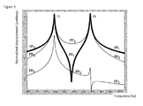
- Figure 3 shows the resonance behavior of the gyroscope shown in Figure 2 : normalized displacement response (unitless) vs. frequency (Hz), in accordance with an embodiment.
- Figure 4 shows a schematic mechanical equivalent of a micromachined gyroscope comprising 3 driving masses m1, m2, m3 and 1 sensing mass m sense whereby the sensing mass is decoupled from the driving mass m3, in accordance with an embodiment.
- Figure 5 shows a schematic mechanical equivalent of a micromachined gyroscope comprising 3 driving masses m1, m2, m3 and 3 sensing mass m sense-2 , m sense-3 whereby the sensing masses are decoupled from the driving mass m3, in accordance with an embodiment.
- Figure 6 shows a schematic mechanical equivalent of a micromachined gyroscope comprising the driving masses m1, m2, m3 are arranged in a tuning fork configuration and 1 sensing mass m sense , in accordance with an embodiment.
- a micromachined gyroscope is disclosed.
- Such a micromachined gyroscope is an angular rate sensor that operates according to the Coriolis Effect described above.
- Such a micromachined gyroscope is manufactured using semiconductor process manufacturing steps.
- a micromachined gyroscope comprising a configuration of 3 masses mechanically coupled to oscillate along a first direction y.
- mass m1 is coupled to mass m2 and to the substrate
- mass m2 is coupled to mass m3 and to the substrate
- mass m3 drives the sensing part m serise .
- Mass m3 is only mechanically coupled to mass m1 via the second mass m2.
- Mass m1 is driven by actuators, which are typically electrostatically actuated.
- actuators which are typically electrostatically actuated.
- comb-drive actuators when operated at lower voltages, can be used, it may be desirable to use parallel plate actuators, as they operate at lower voltages.
- parallel-plate actuators are more power-efficient, although they cannot provide large displacements due to their non-linear behavior.
- the small displacement of the parallel-plate actuators can be amplified, resulting in an appropriately higher oscillation amplitude of the third mass m3.
- the amplitude increase from peak to peak may be several micrometers.
- the third mass m3 is used as the oscillating mass which creates the Coriolis force upon external rotation.
- the deflection of mass m3 is sensed by the mass m sense moving in a direction y perpendicular to the direction x along which the driving masses m1, m2 and m3 oscillates.
- This mass m sense is, in the configuration illustrated by Figure 1 , directly coupled to mass m 3drive and as such is part of the driving mass m3.
- the values of the masses m1, m2, m3, spring constants k1, k2, k3, k12, k23, and the damping levels b1 and b2 are designed to result in a large, and flat (e.g., constant) over a frequency range (e.g., 50Hz or above), displacement response for mass m3, and a mechanical amplification between mass m1 and mass m3 at this flat frequency response of mass m3.
- the amplitude of the oscillation of mass m1 can be small, typically less than 200nm, or even 100nm.
- this small oscillation amplitude of mass m1 allows low voltage actuation of actuators (e.g., parallel-plate actuators or comb-drive actuators).
- actuators e.g., parallel-plate actuators or comb-drive actuators.
- Figure 2 illustrates another embodiment where mass m3 is mechanically coupled to the substrate as well.
- This coupling is modeled by a spring k3 and a damping b3.
- Such a configuration would accommodate for the imperfections coming from the fabrication of the micromachined gyroscope. If the springs k1 and k3 are designed in a similar shape, then even, if there is a process related imperfection, all springs k1, k2, k3, k12, k23 are affected to the same degree.
- anchoring all masses m1, m2 and m3 to the substrate minimizes the mechanical stress related to buckling/bending of the cantilevered masses and allows a larger and flatter device.
- X 1 Force k 1 + k 12 + j ⁇ ⁇ ⁇ b 1 - m 1 ⁇ ⁇ 2 - k 12 2 k 12 + k 2 + k 23 + j ⁇ ⁇ ⁇ b 2 - m 2 ⁇ ⁇ 2 - k 23 2 k 23 + k 3 + j ⁇ ⁇ ⁇ b 3 - m 3 ⁇ ⁇ 2
- X 2 X 1 ⁇ k 12 k 12 + k 2 + k 23 + j ⁇ ⁇ ⁇ b 2 - m 2 ⁇ ⁇ 2 - k 23 2 k 23 + k 3 + j ⁇ ⁇ ⁇ b 3 - m 3 ⁇ ⁇ 2
- X 3 X 2 ⁇ k 23 k 23 + k 3 + j ⁇ ⁇ ⁇ b 3 - m 3 ⁇ ⁇ 2
- X 3 X 2 ⁇ k 23 k 23 + k 3 + j
- Figure 3 illustrates the resonance behavior of the 3 mass coupled oscillation configuration.
- the frequency of the actuating force is swept and the displacement of the actuated mass is measured with respect to the DC displacement.
- the y-axis of Figure 3 is representative for the quality factor of the oscillation peaks.
- response peaks f1 and f3 In-between response peaks f1 and f3 a substantially flat response region is obtained.
- These two resonance peaks f1 and f3 are determined by the mass m1 and mass m3, when the resonance frequency of mass m2 is selected to be higher than either of both resonance peaks.
- mass m2 is considered to be a non-moving rigid body whereby k 2 is assumed to be infinitive. Hence, the motion of mass m1 and mass m3 can be determined separately. Then, the resonant frequencies f1 and f2 of respectively mass m1 and mass m3 are equated to each other, assuming that mass m2 had no impact, as shown in equation (3).
- k 1 + k 12 m 1 k 23 + k 3 m 3
- the finite k 2 value will cause the resonant frequencies f1 of mass m1 and f3 of mass m3 to separate from each other and form a robust response plateau in-between and a mechanical amplification between mass m1 and mass m3.
- the separation of mass m1 and mass m3 resonant frequencies and the response level of mass m3 at the plateau depend on the value of k 2 -The higher k 2 is, the smaller the separation and the larger the response will be.
- This mechanical amplification can be further improved by increasing the vacuum level of the environment in which the gyroscope operates or the quality factor of the individual peaks.
- the position of the anti-resonance frequency of mass m1, where the mechanical amplification is the highest from mass m1 towards mass m3, can be tuned by changing k1.
- the value of k1 can be easily tuned if parallel plate actuators are used to actuate mass m1.
- the gyroscope is operated slightly off the anti-resonance frequency of mass m1 and the mechanical amplification ratio from mass m1 to mass m3 will be around 20-30 regardless of the vacuum level.
- damping levels b1, b2 (and b3 when present) or the quality factors of each resonant peak f1 and f3 have an important role on the operation of the gyroscope. If the quality factors are not large enough, the coupling cannot occur and the plateau cannot be formed.
- the selection of the quality factors of the resonance frequencies f1 and f2 is a design criterion.
- these quality factor values should be one order of magnitude larger than the ratio of mass m2 resonant frequency to the average frequency of the plateau between the resonance frequency f1 and f3 of mass m1 and m3 when coupled via mass m2 due to the finite value of spring k2.
- the position of the anti-resonance of mass m1 does not have to be at the mid-point of this plateau. This position depends on the ratio of mass m1 to mass m3, but can be tuned by altering k 1 . So, although during the initial design phase the resonant frequencies of mass-1 and mass-3 are equated to each other f1 ⁇ f3, thereby assuming mass m2 to be a non-moving body, at the end, equation (3) does not have to hold due to changed k 1 .
- the mechanical amplification between mass-1 and mass-3 depends on the operating frequency. If the operating frequency is at the anti-resonance of mass m1, the amplification ratio will be the maximum. However, this situation can bring instability to the mass m1 motion. It is proposed to operate slightly off anti-resonance. In this case the mechanical amplification ratio can realistically be 20-30.
- FIGS. 4 , 5 and 6 show alternative embodiments.
- the proposed 3-mass coupled oscillation technique can be used wherever a 1-DOF oscillator is used within vibrating gyroscopes. Decoupled or non-decoupled sense and drive schemes and a tuning fork topology can be used. Moreover, this 3-mass oscillation topology can be used in the sensing part of the gyroscope to achieve a large bandwidth and an amplified sensitivity.
- Figure 4 illustrates a micromachined gyroscope comprising 3 driving masses m1, m2 and m3 with mass m1 is coupled (k1, b1) to the substrate and to (k12) mass m2, m2 is coupled to the substrate (k2,b2) and to (k23), while the mass m3 and mass m3 drives the sensing mass m sens via the decoupling mass m decoupling .
- Figure 5 illustrates a micromachined gyroscope comprising 3 driving masses m1, m2 and m3 with mass m1 being coupled (k1, b1) to the substrate and to (k12) mass m2, m2 is coupled to the substrate (k2,b2) and to (k23) the mass m3 and mass m3 drives the sensing mass m sens via the decoupling mass m decoupling .
- the sensing mass m sens is configured as a connection for 3 mass m sens_1 , m sens_2 , m sens_3 , whereby mass m sens_2 is coupled to the substrate and to mass m sens_2 , m sens_2 is coupled to the substrate and the mass m sens_3 .
- Figure 6 illustrates a micromachined gyroscope comprising 3 driving masses m1, m2 and m3 in a tuning fork configuration with mass m1 being coupled (k1, b1) to the substrate and to (k12) mass m2, m2 being coupled to the substrate (k2,b2) and to (k23) the mass m3 and mass m3 driving the sensing mass m sens via the decoupling mass m decoupling .
- Both series of 3 mechanically coupled driving mass m1, m2 and m3 and m1', m2' and m3' are actuated by the same actuators.
- a micromachined gyroscope may include a substrate and 3 masses configured to oscillate along a first direction.
- the first mass m1 may be mechanically coupled to the substrate
- the second mass m2 may be mechanically coupled to the first mass m1 and to substrate
- the third mass m3 may be mechanically coupled to the second mass m2.
- the gyroscope may be defined as follows: [(k2+kl2+k23)/m2] >> ([(k1+k12)/m1] ⁇ [(k23)/m3]), where m1, m2, m3 are the weights of, respectively, the masses m1, m2 and m3, k1, k2 being the spring constant of the mechanical connection between of the respective mass and the substrate, and k12, k23 being the spring constant of the mechanical connection between mass 2 and mass 1 and mass 3 respectively.
- the third mass m3 may be mechanically coupled to the substrate and the following relationship may exist: [(k2+k12+k23)/m2] >> [(k1+k12)/m1] ⁇ [k3+k23)/m3], where k3 is the spring constant of the mechanical connection between of the mass m3 and the substrate.
- the three masses may be driving masses.
- the gyroscope may further include driving means to drive the first mass m1.
- the driving means may be, for example, one or more parallel plate electrostatic actuators.
- the three masses may be sensing masses configured to move when the gyroscope rotates.
- the gyroscope may further include a duplicate of the three-mass configuration.
- the duplicate may be configured to oscillate along the first direction in opposite phase with the three-mass configuration.
- the masses may be configured to oscillate linearly.
- a method for designing a micromachined gyroscope may include selecting m1, m3, k1 and k3 such that [(k1+k12)/m1] ⁇ [k3+k23)/m3]. The method may further include selecting m2, k2 such that during operation [(k2+k12+k23)/m2] >> [(k1+k12)/m1] > [k3+k23)/m3].
- the method may further comprises selecting a mechanical amplification between the movement of mass m1 and mass m3, and dimensioning k2 in view of this desired mechanical amplification.
Landscapes
- Physics & Mathematics (AREA)
- Engineering & Computer Science (AREA)
- General Physics & Mathematics (AREA)
- Radar, Positioning & Navigation (AREA)
- Remote Sensing (AREA)
- Gyroscopes (AREA)
Abstract
Description
- Micromachined gyroscopes are angular rate sensors that typically operate according to a physical phenomenon called the Coriolis Effect. The Coriolis Effect is, simply, the deflection of moving objects viewed from a rotating frame. For an object mounted to a substrate, the object tends to oscillate (e.g., vibrate, move, or drive) in a perpendicular plane when the substrate rotates. Hence, in order to make use of the Coriolis Effect, micromachined gyroscopes may be composed of an oscillating part comprising at least one mass, and a sensing part which is free to move in a perpendicular plane of the oscillating part. The sensing part is affected by the rotation of the gyroscope, as the oscillating part will be deflected. Under an external rotation, the oscillating mass deflects, and that deflection is sensed via the movement of the sensing part.
- The sensitivity of such an oscillating gyroscope depends on its oscillation magnitude. In order to achieve a stable and large sensitivity, stable and large oscillation amplitude is desirable.
- Typically, a large oscillation is achieved by using a one-degree-of-freedom (1-DOF) oscillator that is operated at its resonant frequency. Stability is then obtained with the help of stabilization circuitry (e.g., phase lock loops (PLLs), proportional integral (PI) controllers, etc.) to keep the gyroscope operating near this resonance frequency.
- In some cases, the 1-DOF oscillator may be operated at non-resonance frequency, thereby reducing the need for stabilisation circuitry. However, a magnitude of the oscillation at non-resonance frequencies will be less than a magnitude of the oscillation at the resonance frequency. When the oscillator is oscillating at non-resonance frequencies, though, changes in the frequency, as well as the quality factor, will have a lesser effect on the oscillation magnitude, as compared to when the oscillator is oscillating at the resonance frequency.
- Typical gyroscopes consume 10 to 20 times more power than a typical accelerometer in commercial applications. Some of this power consumption results from the comb-drive actuation used in typical gyroscopes to obtain large oscillation magnitudes. Comb-drive actuation involves electrostatic forces being generated between two comb-like structures. One comb is fixed to the substrate while the other comb is movable. The force developed by the comb-drive actuator is proportional to the change in capacitance between the two combs. However, this capacitance increases with driving voltage difference between both combs, with the coupling area reflected by the number of comb teeth, and the gap between these teeth. As a result, achieving large oscillation magnitudes with comb-drive actuation requires large polarization voltage differences, typically 12V in commercial devices. Such high polarization voltage differences are not conducive to a low-power gyroscope. Another source of this power consumption may be stabilization circuitry, such as PLLs and/or PI controllers, used to stabilize the oscillation increase power consumption of the gyroscope, which is similarly not conducive to a low-power gyroscope. Other sources of power consumption exist as well.
- One option for reducing the power consumption of a gyroscope is to use a two-degree-of-freedom (2-DOF) oscillator that includes two masses and, accordingly, has two resonance frequencies. The 2-DOF gyroscope may be operated in between the two resonance frequencies. The amplitude response typically has minimal dependency on the varying quality factor and the resonance frequencies. However, the magnitude of this response is still very small and comparable to the non-resonance response of the 1-DOF oscillator discussed above.
- Accordingly, a micromachined gyroscope with reduced power consumption may be desirable. It may be desirable for such a micromachined gyroscope to have a stable oscillation frequency range with a high mechanical amplification between the actuator and the driving part.
- Disclosed is a gyroscope with reduced power consumption, as compared to typical gyroscopes. The disclosed gyroscope is designed without the need of stabilization circuitry, and with a reduced need for driving and controlling circuitry, thereby reducing the power consumption of the gyroscope.
- In one aspect, a micromachined gyroscope is disclosed. The micromachined gyroscope comprises a substrate and at least three masses (m1, m2, m3). The first mass m1 is mechanically coupled to the substrate via a mechanical connection k1, the second mass m2 is mechanically coupled to the first mass m1 via a connection k12 and to the substrate via a mechanical connection k2, and the third mass m3 is mechanically coupled to the second mass m2 via a mechanical connection k23. The three masses are each configured to oscillate along a first direction x or y.
- The following relationships exist between the masses m1, m2, m3, and the mechanical connections k1, k2, k12, k23: [(k2+k12+k23)/m2] >>([(k1+k12)/m1] ∼ [(k23)/m3])
- In some embodiments, the third mass m3 is also mechanically coupled to the substrate via a mechanically connection k3.
- The masses m1, m2 and m3 can be the driving masses of the gyroscope configured to oscillate along a first direction x. To this end, the gyroscope may further comprise actuators for stimulating these driving masses. These actuators may be parallel plate actuators.
- In another embodiment, the micromachined gyroscope further comprises a duplicate m1' m2' and m3' of these 3 mass configuration and this duplicate is configured to oscillate along the first direction x but in opposite phase with these 3 masses m1, m2 and m3.
- The masses m1, m2 and m3 can be the sensing masses of the gyroscope, which are configured to oscillate along a first direction y when the gyroscope is rotating.
- In some embodiments, the 3 masses m1, m2, m3 can be configured to oscillate in a linear way.
- In another aspect, a micromachined gyroscope is disclosed comprising a substrate, a driving mass mechanically coupled to a sensing mass, both masses being movable in perpendicular directions and, when in operation under the influence of the Coriolis force, the driving mass causes the driving of the sensing mass, whereby at least one of the driving mass or of the sensing mass is configured as a connection of 3 masses m1, m2, m3, whereby the first mass m1 is mechanically coupled to the substrate, the second mass m2 is mechanically coupled to the first mass m1 and to substrate, and the third mass m3 is mechanically coupled to the second mass m2, whereby the following relationship exist [(k2+k12+k23)/m2] >> ([(k1+k12)/m1] ∼ [(k23)/m3]) with m1, m2, m3 being the weight of respectively mass m1, m2 and m3, with k1, k2 (and k3) being the spring constant of the mechanical connection between of the respective mass m1 or m2 or m3 and the substrate, and with k12, k23 being the spring constant of the mechanical connection between mass m2 and mass m1 or mass m3 respectively.
- In yet another aspect, a micromachined gyroscope is disclosed comprising a substrate, 3 masses m1, m2 and m3 , configured to oscillate along a first direction x or y, whereby the first mass m1 is mechanically coupled to the substrate, the second mass m2 is mechanically coupled to the first mass m1 and to substrate, and the third mass m3 is mechanically coupled to the second mass m2, whereby the weight and the spring constants k1, k2, k3 of the respective masses m1, m2 and m3 and mechanical couplings k12, k23 are selected, such that, during operation mass m2 oscillates at a frequency substantially above the resonance frequencies of mass m1 and mass m3.
- In some embodiments, the resonance frequency of mass m2 is at least 2 times, or even 2.5 times, higher than the resonance frequency of mass m1 or m3.
- In yet another aspect, a method for designing a micromachined gyroscope is disclosed. This micromachined gyroscope comprises a substrate, at least 3 masses m1, m2, m3 being configured to oscillate along a first direction x or y, whereby the first mass m1 is mechanically coupled to the substrate, the second mass m2 is mechanically coupled to the first mass m1 and to substrate, and the third mass m3 is mechanically coupled to the second mass m2, whereby the following relationship exist [(k2+k12+k23)/m2] >> ([(k1+k12)/m1] ∼ [(k23)/m3]) with m1, m2, m3 being the weight of respectively mass m1, m2 and m3, with k1, k2 (and k3) being the spring constant of the mechanical connection between of the respective mass m1 or m2 or m3 and the substrate, and with k12, k23 being the spring constant of the mechanical connection between mass m2 and mass m1 or mass m3 respectively.
- The method comprises: selecting m1, m3, k1 and k3 whereby [(k1+k12)/m1] [(k3+k23)/m3], and selecting m2, k2 such that during operation of the gyroscope [(k2+k12+k23)/m2] >> ([(k1+k12)/m1] > [(k3+k23)/m3]).
- The method further comprises selecting a mechanical amplification between the movement of mass m1 and mass m3 and dimensioning k2 in view of this desired mechanical amplification.
- Exemplary embodiments are illustrated in referenced figures of the drawings. It is intended that the embodiments and figures disclosed herein are to be considered illustrative rather than restrictive.
-
Figure 1 shows a schematic mechanical equivalent of a micromachined gyroscope comprising 3 driving masses m1, m2, m3 and 1 sensing mass msense, in accordance with an embodiment. -
Figure 2 shows a schematic mechanical equivalent of a micromachined gyroscope comprising 3 driving masses m1, m2, m3 and I sensing mass msense, in which mass m3 is coupled to the substrate, in accordance with an embodiment. -
Figure 3 shows the resonance behavior of the gyroscope shown inFigure 2 : normalized displacement response (unitless) vs. frequency (Hz), in accordance with an embodiment. -
Figure 4 shows a schematic mechanical equivalent of a micromachined gyroscope comprising 3 driving masses m1, m2, m3 and 1 sensing mass msense whereby the sensing mass is decoupled from the driving mass m3, in accordance with an embodiment. -
Figure 5 shows a schematic mechanical equivalent of a micromachined gyroscope comprising 3 driving masses m1, m2, m3 and 3 sensing mass msense-2, msense-3 whereby the sensing masses are decoupled from the driving mass m3, in accordance with an embodiment. -
Figure 6 shows a schematic mechanical equivalent of a micromachined gyroscope comprising the driving masses m1, m2, m3 are arranged in a tuning fork configuration and 1 sensing mass msense, in accordance with an embodiment. - The present disclosure contains particular embodiments and with reference to certain drawings but the disclosure is not limited thereto. The drawings described are only schematic and are non-limiting. In the drawings, the size of some of the elements may be exaggerated and not drawn on scale for illustrative purposes. The dimensions and the relative dimensions do not correspond to actual reductions to practice of the disclosure. Reference throughout this specification to "one embodiment" or "an embodiment" means that a particular feature, structure or characteristic described in connection with the embodiment is included in at least one embodiment of the present disclosure. Thus, appearances of the phrases "in one embodiment" or "in an embodiment" in various places throughout this specification are not necessarily all referring to the same embodiment, but may refer to different embodiments. Furthermore, the particular features, structures or characteristics may be combined in any suitable manner, as would be apparent to one of ordinary skill in the art from this disclosure, in one or more embodiments. The terms top, bottom, over, under and the like in the description and the claims are used for descriptive purposes and not necessarily for describing relative positions. It is to be understood that the terms so used are interchangeable under appropriate circumstances and that the embodiments of the disclosure described herein are capable of operation in other orientations than described or illustrated herein. It is to be noticed that the term "comprising", used in the claims, should not be interpreted as being restricted to the means listed thereafter; it does not exclude other elements or steps. It is thus to be interpreted as specifying the presence of the stated features, integers, steps or components as referred to, but does not preclude the presence or addition of one or more other features, integers, steps or components, or groups thereof. Thus, the scope of the expression "a solution comprising components A and B" should not be limited to solution consisting only of components A and B. It means that with respect to the present disclosure, the only relevant components of the solution are A and B.
- In this disclosure a micromachined gyroscope is disclosed. Such a micromachined gyroscope is an angular rate sensor that operates according to the Coriolis Effect described above. Such a micromachined gyroscope is manufactured using semiconductor process manufacturing steps.
- More particularly, a micromachined gyroscope is disclosed comprising a configuration of 3 masses mechanically coupled to oscillate along a first direction y. In such a 3-mass oscillation scheme, illustrated by
Figure 1 , mass m1 is coupled to mass m2 and to the substrate, mass m2 is coupled to mass m3 and to the substrate, while mass m3 drives the sensing part mserise. Mass m3 is only mechanically coupled to mass m1 via the second mass m2. - Mass m1 is driven by actuators, which are typically electrostatically actuated. Although comb-drive actuators, when operated at lower voltages, can be used, it may be desirable to use parallel plate actuators, as they operate at lower voltages. Such parallel-plate actuators are more power-efficient, although they cannot provide large displacements due to their non-linear behavior. However, thanks to the mechanical amplification between the movement of mass m1 and mass m3 as discussed below, the small displacement of the parallel-plate actuators can be amplified, resulting in an appropriately higher oscillation amplitude of the third mass m3. For example, the amplitude increase from peak to peak may be several micrometers.
- The third mass m3 is used as the oscillating mass which creates the Coriolis force upon external rotation. The deflection of mass m3 is sensed by the mass msense moving in a direction y perpendicular to the direction x along which the driving masses m1, m2 and m3 oscillates. This mass msense is, in the configuration illustrated by
Figure 1 , directly coupled to mass m3drive and as such is part of the driving mass m3. - The values of the masses m1, m2, m3, spring constants k1, k2, k3, k12, k23, and the damping levels b1 and b2 are designed to result in a large, and flat (e.g., constant) over a frequency range (e.g., 50Hz or above), displacement response for mass m3, and a mechanical amplification between mass m1 and mass m3 at this flat frequency response of mass m3. Hence, the amplitude of the oscillation of mass m1 can be small, typically less than 200nm, or even 100nm. As discussed above, this small oscillation amplitude of mass m1 allows low voltage actuation of actuators (e.g., parallel-plate actuators or comb-drive actuators). Hence, the response of mass m3 to the actuators will be robust without needing of any external circuitry, and overall power consumption will drop.
- Whereas in
Figure 1 mass m3 was not coupled to the substrate,Figure 2 illustrates another embodiment where mass m3 is mechanically coupled to the substrate as well. This coupling is modeled by a spring k3 and a damping b3. Such a configuration would accommodate for the imperfections coming from the fabrication of the micromachined gyroscope. If the springs k1 and k3 are designed in a similar shape, then even, if there is a process related imperfection, all springs k1, k2, k3, k12, k23 are affected to the same degree. Moreover, anchoring all masses m1, m2 and m3 to the substrate minimizes the mechanical stress related to buckling/bending of the cantilevered masses and allows a larger and flatter device. - The mechanical system illustrated by
Figure 2 can be modeled by three equations (1):


- From these 3 equations, the displacement responses of each mass m1, m2 and m3 can be derived analytically (2):


-
Figure 3 illustrates the resonance behavior of the 3 mass coupled oscillation configuration. The frequency of the actuating force is swept and the displacement of the actuated mass is measured with respect to the DC displacement. Hence, the y-axis ofFigure 3 is representative for the quality factor of the oscillation peaks. In-between response peaks f1 and f3 a substantially flat response region is obtained. These two resonance peaks f1 and f3 are determined by the mass m1 and mass m3, when the resonance frequency of mass m2 is selected to be higher than either of both resonance peaks. - In order to achieve a flat and large mass m3 response and a mechanical amplification between mass m1 and mass m3, the following design method is applied. First, mass m2 is considered to be a non-moving rigid body whereby k2 is assumed to be infinitive. Hence, the motion of mass m1 and mass m3 can be determined separately. Then, the resonant frequencies f1 and f2 of respectively mass m1 and mass m3 are equated to each other, assuming that mass m2 had no impact, as shown in equation (3).

- If the damping levels b1 and b2, and when coupled to the substrate b3, are low enough, the finite k2 value will cause the resonant frequencies f1 of mass m1 and f3 of mass m3 to separate from each other and form a robust response plateau in-between and a mechanical amplification between mass m1 and mass m3. The separation of mass m1 and mass m3 resonant frequencies and the response level of mass m3 at the plateau depend on the value of k2-The higher k2 is, the smaller the separation and the larger the response will be.
- This mechanical amplification can be further improved by increasing the vacuum level of the environment in which the gyroscope operates or the quality factor of the individual peaks.
- The position of the anti-resonance frequency of mass m1, where the mechanical amplification is the highest from mass m1 towards mass m3, can be tuned by changing k1. The value of k1 can be easily tuned if parallel plate actuators are used to actuate mass m1. However, from the application point of view, one might prefer to not operate at the anti-resonance frequency of mass m1, because that will be unstable for mass m1. In that case, the gyroscope is operated slightly off the anti-resonance frequency of mass m1 and the mechanical amplification ratio from mass m1 to mass m3 will be around 20-30 regardless of the vacuum level.
- The damping levels b1, b2 (and b3 when present) or the quality factors of each resonant peak f1 and f3 have an important role on the operation of the gyroscope. If the quality factors are not large enough, the coupling cannot occur and the plateau cannot be formed.
- The selection of the quality factors of the resonance frequencies f1 and f2 is a design criterion. The larger k2 is, the larger the quality factors of both resonance frequencies should be. As a rule of thumb, these quality factor values should be one order of magnitude larger than the ratio of mass m2 resonant frequency to the average frequency of the plateau between the resonance frequency f1 and f3 of mass m1 and m3 when coupled via mass m2 due to the finite value of spring k2.
- The position of the anti-resonance of mass m1 does not have to be at the mid-point of this plateau. This position depends on the ratio of mass m1 to mass m3, but can be tuned by altering k1. So, although during the initial design phase the resonant frequencies of mass-1 and mass-3 are equated to each other f1∼f3, thereby assuming mass m2 to be a non-moving body, at the end, equation (3) does not have to hold due to changed k1.
- The mechanical amplification between mass-1 and mass-3 depends on the operating frequency. If the operating frequency is at the anti-resonance of mass m1, the amplification ratio will be the maximum. However, this situation can bring instability to the mass m1 motion. It is proposed to operate slightly off anti-resonance. In this case the mechanical amplification ratio can realistically be 20-30.
-
Figures 4 ,5 and6 show alternative embodiments. The proposed 3-mass coupled oscillation technique can be used wherever a 1-DOF oscillator is used within vibrating gyroscopes. Decoupled or non-decoupled sense and drive schemes and a tuning fork topology can be used. Moreover, this 3-mass oscillation topology can be used in the sensing part of the gyroscope to achieve a large bandwidth and an amplified sensitivity. -
Figure 4 illustrates a micromachined gyroscope comprising 3 driving masses m1, m2 and m3 with mass m1 is coupled (k1, b1) to the substrate and to (k12) mass m2, m2 is coupled to the substrate (k2,b2) and to (k23), while the mass m3 and mass m3 drives the sensing mass msens via the decoupling mass mdecoupling. -
Figure 5 illustrates a micromachined gyroscope comprising 3 driving masses m1, m2 and m3 with mass m1 being coupled (k1, b1) to the substrate and to (k12) mass m2, m2 is coupled to the substrate (k2,b2) and to (k23) the mass m3 and mass m3 drives the sensing mass msens via the decoupling mass mdecoupling. In this embodiment also the sensing mass msens is configured as a connection for 3 mass msens_1, msens_2, msens_3, whereby mass msens_2 is coupled to the substrate and to mass msens_2, msens_2 is coupled to the substrate and the mass msens_3. In this configuration a stable oscillation frequency range for the driving masses is obtained whereby the movement of mass m1 is mechanically amplified to mass m3, but also a stable sensing frequency range is obtained whereby the movement of mass msens_1is mechanically amplified to mass msens_3. -
Figure 6 illustrates a micromachined gyroscope comprising 3 driving masses m1, m2 and m3 in a tuning fork configuration with mass m1 being coupled (k1, b1) to the substrate and to (k12) mass m2, m2 being coupled to the substrate (k2,b2) and to (k23) the mass m3 and mass m3 driving the sensing mass msens via the decoupling mass mdecoupling. It further comprises a second series of 3 driving masses m1', m2' and m3' with mass m1' being coupled to the substrate and to (k12') mass m2', m2' being coupled to the substrate and to (k23') the mass m3' and mass m3' driving the sensing mass msens'. Both series of 3 mechanically coupled driving mass m1, m2 and m3 and m1', m2' and m3' are actuated by the same actuators. - A number of example embodiments are contemplated. In one example embodiment, a micromachined gyroscope may include a substrate and 3 masses configured to oscillate along a first direction. The first mass m1 may be mechanically coupled to the substrate, the second mass m2 may be mechanically coupled to the first mass m1 and to substrate, and the third mass m3 may be mechanically coupled to the second mass m2. The gyroscope may be defined as follows: [(k2+kl2+k23)/m2] >> ([(k1+k12)/m1] ∼ [(k23)/m3]), where m1, m2, m3 are the weights of, respectively, the masses m1, m2 and m3, k1, k2 being the spring constant of the mechanical connection between of the respective mass and the substrate, and k12, k23 being the spring constant of the mechanical connection between mass 2 and mass 1 and mass 3 respectively.
- In some embodiments, the third mass m3 may be mechanically coupled to the substrate and the following relationship may exist: [(k2+k12+k23)/m2] >> [(k1+k12)/m1] ∼ [k3+k23)/m3], where k3 is the spring constant of the mechanical connection between of the mass m3 and the substrate.
- In some embodiments, the three masses may be driving masses. The gyroscope may further include driving means to drive the first mass m1. The driving means may be, for example, one or more parallel plate electrostatic actuators.
- In some embodiments, the three masses may be sensing masses configured to move when the gyroscope rotates.
- In some embodiments, the gyroscope may further include a duplicate of the three-mass configuration. The duplicate may be configured to oscillate along the first direction in opposite phase with the three-mass configuration.
- In some embodiments, the masses may be configured to oscillate linearly.
- In another example embodiment, a method for designing a micromachined gyroscope may include selecting m1, m3, k1 and k3 such that [(k1+k12)/m1] ∼ [k3+k23)/m3]. The method may further include selecting m2, k2 such that during operation [(k2+k12+k23)/m2] >> [(k1+k12)/m1] > [k3+k23)/m3].
- In some embodiments, the method may further comprises selecting a mechanical amplification between the movement of mass m1 and mass m3, and dimensioning k2 in view of this desired mechanical amplification.
Claims (9)
- A micromachined gyroscope comprising: a substrate (s) and 3 masses (m1, m2, m3) configured to oscillate along a first direction, whereby the first mass (m1) being mechanically coupled to the substrate (s), the second mass (m2) being mechanically coupled to the first mass (m1) and to the substrate, and the third mass (m3) being mechanically coupled to the second mass (m2), whereby the following relationship exist [(k2+k12+k23)/m2] >> ([(k1+k12)/m1] ∼ [(k23)/m3]), with m1, m2, m3 being the weight of respectively the first, the second and the third mass, with k1, k2 and k3 being the spring constant of the mechanical connection between of the respectively the first, the second or second mass and the substrate, and with k12, k23 being the spring constant of the mechanical connection between the second mass and respectively the first or the third mass.
- The micromachined gyroscope of claim 1, wherein the third mass (m3) is mechanically coupled to the substrate (s) and whereby the following relationship exists: [(k2+k12+k23)/m2] >> [(k1+k12)/m1] ∼ [k3+k23)/m3], with m1, m2, m3 being the weight of respectively the first, the second and the third mass, with k1, k2 (and k3) being the spring constant of the mechanical connection between of the respectively the first, the second or second mass and the substrate, and with k12, k23 being the spring constant of the mechanical connection between the second mass and respectively the first or the third mass.
- The micromachined gyroscope of claim 1 or 2, wherein the 3 masses (m1, m2, m3) are the driving masses and further comprising driving means to drive the first mass (m1).
- The micromachined gyroscope of claim 3, wherein the driving means are parallel plate electrostatic actuators.
- The micromachined gyroscope of any of the claims 1 to 4, wherein the 3 masses (m1, m2, m3) are the sensing masses configured to move when rotating the gyroscope.
- The micromachined gyroscope of any of the claims 1 to 5, further comprising a duplicate (m1' m2', m3') of this 3 mass configuration (m1, m2, m3), this duplicate being configured to oscillate along the first direction but in opposite phase with this 3 mass configuration (m1, m2, m3).
- The micromachined gyroscope of any of the claims 1 to 6, wherein the 3 masses (m1, m2, m3, m1', m2', m3') are configured to oscillate in a linear way.
- A method for designing a micromachined gyroscope according to any of the foregoing claims, the method comprising:selecting the first mass (m1), the spring constant (k1) between the first mass (m1) and the substrate (s), the third mass (m3), and the spring constant (k3) between the third mass andthe substrate whereby [(k1+k12)/m1] ∼ [k3+k23)/m3], and,selecting the second mass (m2) and the spring constant (k2) between the second mass andthe substrate, such that, during operation, [(k2+k12+k23)/m2] >> [(k1+k12)/m1] > [k3+k23)/m3], with m1, m2, m3 being the weight of respectively the first, the second andthe third mass, with k1, k2 (and k3) being the spring constant of the mechanical connection between of the respectively the first, the second or second mass and the substrate, and with k12, k23 being the spring constant of the mechanical connection between the second mass and respectively the first or the third mass.
- A method according to claim 8, further comprising selecting a mechanical amplification between the movement of first mass (m1) and the third mass (m3), and dimensioning the spring constant (k2) between the second mass and the substrate in view of this desired mechanical amplification.
Applications Claiming Priority (1)
| Application Number | Priority Date | Filing Date | Title |
|---|---|---|---|
| US201161534146P | 2011-09-13 | 2011-09-13 |
Publications (3)
| Publication Number | Publication Date |
|---|---|
| EP2570770A2 true EP2570770A2 (en) | 2013-03-20 |
| EP2570770A3 EP2570770A3 (en) | 2016-03-30 |
| EP2570770B1 EP2570770B1 (en) | 2021-06-23 |
Family
ID=46762913
Family Applications (1)
| Application Number | Title | Priority Date | Filing Date |
|---|---|---|---|
| EP12182539.2A Active EP2570770B1 (en) | 2011-09-13 | 2012-08-31 | Three-mass coupled oscillation technique for mechanically robust micromachined gyroscopes |
Country Status (3)
| Country | Link |
|---|---|
| US (1) | US8955381B2 (en) |
| EP (1) | EP2570770B1 (en) |
| JP (1) | JP2013061338A (en) |
Cited By (5)
| Publication number | Priority date | Publication date | Assignee | Title |
|---|---|---|---|---|
| CN105091875A (en) * | 2014-05-21 | 2015-11-25 | 因文森斯公司 | Mems sensor with decoupled drive system |
| US9395183B2 (en) | 2011-09-16 | 2016-07-19 | Invensense, Inc. | Micromachined gyroscope including a guided mass system |
| US9863769B2 (en) | 2011-09-16 | 2018-01-09 | Invensense, Inc. | MEMS sensor with decoupled drive system |
| US9958271B2 (en) | 2014-01-21 | 2018-05-01 | Invensense, Inc. | Configuration to reduce non-linear motion |
| US10914584B2 (en) | 2011-09-16 | 2021-02-09 | Invensense, Inc. | Drive and sense balanced, semi-coupled 3-axis gyroscope |
Family Cites Families (5)
| Publication number | Priority date | Publication date | Assignee | Title |
|---|---|---|---|---|
| DE4414237A1 (en) * | 1994-04-23 | 1995-10-26 | Bosch Gmbh Robert | Micromechanical vibrator of an oscillation gyrometer |
| DE19827688A1 (en) * | 1997-06-20 | 1999-01-28 | Aisin Seiki | Angular velocity sensor |
| US7377167B2 (en) * | 2004-02-27 | 2008-05-27 | The Regents Of The University Of California | Nonresonant micromachined gyroscopes with structural mode-decoupling |
| US8020441B2 (en) * | 2008-02-05 | 2011-09-20 | Invensense, Inc. | Dual mode sensing for vibratory gyroscope |
| JP2008281485A (en) * | 2007-05-11 | 2008-11-20 | Toyota Motor Corp | Angular velocity detector |
-
2012
- 2012-08-31 EP EP12182539.2A patent/EP2570770B1/en active Active
- 2012-09-12 JP JP2012200751A patent/JP2013061338A/en active Pending
- 2012-09-13 US US13/613,770 patent/US8955381B2/en active Active
Non-Patent Citations (1)
| Title |
|---|
| None |
Cited By (11)
| Publication number | Priority date | Publication date | Assignee | Title |
|---|---|---|---|---|
| US9395183B2 (en) | 2011-09-16 | 2016-07-19 | Invensense, Inc. | Micromachined gyroscope including a guided mass system |
| US9863769B2 (en) | 2011-09-16 | 2018-01-09 | Invensense, Inc. | MEMS sensor with decoupled drive system |
| US10914584B2 (en) | 2011-09-16 | 2021-02-09 | Invensense, Inc. | Drive and sense balanced, semi-coupled 3-axis gyroscope |
| US11815354B2 (en) | 2011-09-16 | 2023-11-14 | Invensense, Inc. | Drive and sense balanced, semi-coupled 3-axis gyroscope |
| US12228404B2 (en) | 2011-09-16 | 2025-02-18 | Invensense, Inc. | Drive and sense balanced, semi-coupled 3-axis gyroscope |
| US9958271B2 (en) | 2014-01-21 | 2018-05-01 | Invensense, Inc. | Configuration to reduce non-linear motion |
| US10527421B2 (en) | 2014-01-21 | 2020-01-07 | Invensense, Inc. | Configuration to reduce non-linear motion |
| US11047685B2 (en) | 2014-01-21 | 2021-06-29 | Invensense, Inc. | Configuration to reduce non-linear motion |
| CN105091875A (en) * | 2014-05-21 | 2015-11-25 | 因文森斯公司 | Mems sensor with decoupled drive system |
| EP2955480A3 (en) * | 2014-05-21 | 2016-03-16 | InvenSense, Inc. | Mems sensor with decoupled drive system |
| CN105091875B (en) * | 2014-05-21 | 2019-08-02 | 应美盛公司 | MEMS sensor with decoupling drive system |
Also Published As
| Publication number | Publication date |
|---|---|
| US20130061673A1 (en) | 2013-03-14 |
| EP2570770B1 (en) | 2021-06-23 |
| JP2013061338A (en) | 2013-04-04 |
| EP2570770A3 (en) | 2016-03-30 |
| US8955381B2 (en) | 2015-02-17 |
Similar Documents
| Publication | Publication Date | Title |
|---|---|---|
| KR101166866B1 (en) | Mems gyroscope with horizontally oriented drive electrodes | |
| JP4343273B2 (en) | Temperature insensitive silicon oscillator and precision voltage reference formed therefrom | |
| US8272266B2 (en) | Gyroscopes using surface electrodes | |
| US7043985B2 (en) | High-resolution in-plane tuning fork gyroscope and methods of fabrication | |
| US7051590B1 (en) | Structure for attenuation or cancellation of quadrature error | |
| KR101100021B1 (en) | 축 -axis angular velocity sensor | |
| US7726189B2 (en) | Nonlinear micromechanical resonator | |
| US11296671B2 (en) | MEMS frequency-tuning springs | |
| US20200011666A1 (en) | Vibratory gyroscope utilizing the nonlinear modal interaction | |
| KR20040057182A (en) | Horizontal and tuning fork vibratory micro gyroscope | |
| JPH11337345A (en) | Vibratory microgyrometer | |
| EP2570770B1 (en) | Three-mass coupled oscillation technique for mechanically robust micromachined gyroscopes | |
| US9509278B2 (en) | Rotational MEMS resonator for oscillator applications | |
| US9528830B2 (en) | Angular rate sensor | |
| WO2014043141A2 (en) | Tuning fork gyroscope time domain inertial sensor | |
| WO2018105132A1 (en) | Vibration energy harvester using stochastic resonance and vibration energy harvesting system using same | |
| Khirallah | Parametric excitation, amplification, and tuning of MEMS folded-beam comb drive oscillator | |
| Khan et al. | Design and development of a MEMS butterfly resonator using synchronizing beam and out of plane actuation | |
| US20160349053A1 (en) | Micromachined Resonating Beam Gyroscopes | |
| US20190112181A1 (en) | Stabile micromechanical devices | |
| Li et al. | Performance-enhanced micro-machined resonant systems with two-degrees-of-freedom resonators | |
| EP2775258B1 (en) | Microelectromechanical gyroscope | |
| Zega et al. | Integrated structure for a resonant micro-gyroscope and accelerometer | |
| Nazdrowicz et al. | Importance of modal analysis in vibratory microgyroscopes | |
| Vinotha et al. | A Novel Design of Electrostatic Actuation Based on Comb Drive MEMS Resonator Using Vibrating Energy Storage Application |
Legal Events
| Date | Code | Title | Description |
|---|---|---|---|
| PUAI | Public reference made under article 153(3) epc to a published international application that has entered the european phase |
Free format text: ORIGINAL CODE: 0009012 |
|
| AK | Designated contracting states |
Kind code of ref document: A2 Designated state(s): AL AT BE BG CH CY CZ DE DK EE ES FI FR GB GR HR HU IE IS IT LI LT LU LV MC MK MT NL NO PL PT RO RS SE SI SK SM TR |
|
| AX | Request for extension of the european patent |
Extension state: BA ME |
|
| PUAL | Search report despatched |
Free format text: ORIGINAL CODE: 0009013 |
|
| AK | Designated contracting states |
Kind code of ref document: A3 Designated state(s): AL AT BE BG CH CY CZ DE DK EE ES FI FR GB GR HR HU IE IS IT LI LT LU LV MC MK MT NL NO PL PT RO RS SE SI SK SM TR |
|
| AX | Request for extension of the european patent |
Extension state: BA ME |
|
| RIC1 | Information provided on ipc code assigned before grant |
Ipc: G01C 19/5733 20120101AFI20160224BHEP |
|
| 17P | Request for examination filed |
Effective date: 20160930 |
|
| RBV | Designated contracting states (corrected) |
Designated state(s): AL AT BE BG CH CY CZ DE DK EE ES FI FR GB GR HR HU IE IS IT LI LT LU LV MC MK MT NL NO PL PT RO RS SE SI SK SM TR |
|
| STAA | Information on the status of an ep patent application or granted ep patent |
Free format text: STATUS: REQUEST FOR EXAMINATION WAS MADE |
|
| RAP1 | Party data changed (applicant data changed or rights of an application transferred) |
Owner name: IMEC VZW |
|
| STAA | Information on the status of an ep patent application or granted ep patent |
Free format text: STATUS: EXAMINATION IS IN PROGRESS |
|
| 17Q | First examination report despatched |
Effective date: 20181009 |
|
| GRAP | Despatch of communication of intention to grant a patent |
Free format text: ORIGINAL CODE: EPIDOSNIGR1 |
|
| STAA | Information on the status of an ep patent application or granted ep patent |
Free format text: STATUS: GRANT OF PATENT IS INTENDED |
|
| INTG | Intention to grant announced |
Effective date: 20210129 |
|
| RIN1 | Information on inventor provided before grant (corrected) |
Inventor name: ERISMIS, MEHMET AKIF |
|
| GRAS | Grant fee paid |
Free format text: ORIGINAL CODE: EPIDOSNIGR3 |
|
| GRAA | (expected) grant |
Free format text: ORIGINAL CODE: 0009210 |
|
| STAA | Information on the status of an ep patent application or granted ep patent |
Free format text: STATUS: THE PATENT HAS BEEN GRANTED |
|
| AK | Designated contracting states |
Kind code of ref document: B1 Designated state(s): AL AT BE BG CH CY CZ DE DK EE ES FI FR GB GR HR HU IE IS IT LI LT LU LV MC MK MT NL NO PL PT RO RS SE SI SK SM TR |
|
| REG | Reference to a national code |
Ref country code: GB Ref legal event code: FG4D |
|
| REG | Reference to a national code |
Ref country code: CH Ref legal event code: EP |
|
| REG | Reference to a national code |
Ref country code: DE Ref legal event code: R096 Ref document number: 602012075892 Country of ref document: DE Ref country code: AT Ref legal event code: REF Ref document number: 1404668 Country of ref document: AT Kind code of ref document: T Effective date: 20210715 |
|
| REG | Reference to a national code |
Ref country code: IE Ref legal event code: FG4D |
|
| REG | Reference to a national code |
Ref country code: LT Ref legal event code: MG9D |
|
| PG25 | Lapsed in a contracting state [announced via postgrant information from national office to epo] |
Ref country code: LT Free format text: LAPSE BECAUSE OF FAILURE TO SUBMIT A TRANSLATION OF THE DESCRIPTION OR TO PAY THE FEE WITHIN THE PRESCRIBED TIME-LIMIT Effective date: 20210623 Ref country code: FI Free format text: LAPSE BECAUSE OF FAILURE TO SUBMIT A TRANSLATION OF THE DESCRIPTION OR TO PAY THE FEE WITHIN THE PRESCRIBED TIME-LIMIT Effective date: 20210623 Ref country code: HR Free format text: LAPSE BECAUSE OF FAILURE TO SUBMIT A TRANSLATION OF THE DESCRIPTION OR TO PAY THE FEE WITHIN THE PRESCRIBED TIME-LIMIT Effective date: 20210623 Ref country code: BG Free format text: LAPSE BECAUSE OF FAILURE TO SUBMIT A TRANSLATION OF THE DESCRIPTION OR TO PAY THE FEE WITHIN THE PRESCRIBED TIME-LIMIT Effective date: 20210923 |
|
| REG | Reference to a national code |
Ref country code: AT Ref legal event code: MK05 Ref document number: 1404668 Country of ref document: AT Kind code of ref document: T Effective date: 20210623 |
|
| PG25 | Lapsed in a contracting state [announced via postgrant information from national office to epo] |
Ref country code: NO Free format text: LAPSE BECAUSE OF FAILURE TO SUBMIT A TRANSLATION OF THE DESCRIPTION OR TO PAY THE FEE WITHIN THE PRESCRIBED TIME-LIMIT Effective date: 20210923 Ref country code: GR Free format text: LAPSE BECAUSE OF FAILURE TO SUBMIT A TRANSLATION OF THE DESCRIPTION OR TO PAY THE FEE WITHIN THE PRESCRIBED TIME-LIMIT Effective date: 20210924 Ref country code: LV Free format text: LAPSE BECAUSE OF FAILURE TO SUBMIT A TRANSLATION OF THE DESCRIPTION OR TO PAY THE FEE WITHIN THE PRESCRIBED TIME-LIMIT Effective date: 20210623 Ref country code: RS Free format text: LAPSE BECAUSE OF FAILURE TO SUBMIT A TRANSLATION OF THE DESCRIPTION OR TO PAY THE FEE WITHIN THE PRESCRIBED TIME-LIMIT Effective date: 20210623 Ref country code: SE Free format text: LAPSE BECAUSE OF FAILURE TO SUBMIT A TRANSLATION OF THE DESCRIPTION OR TO PAY THE FEE WITHIN THE PRESCRIBED TIME-LIMIT Effective date: 20210623 |
|
| REG | Reference to a national code |
Ref country code: NL Ref legal event code: MP Effective date: 20210623 |
|
| PG25 | Lapsed in a contracting state [announced via postgrant information from national office to epo] |
Ref country code: SK Free format text: LAPSE BECAUSE OF FAILURE TO SUBMIT A TRANSLATION OF THE DESCRIPTION OR TO PAY THE FEE WITHIN THE PRESCRIBED TIME-LIMIT Effective date: 20210623 Ref country code: SM Free format text: LAPSE BECAUSE OF FAILURE TO SUBMIT A TRANSLATION OF THE DESCRIPTION OR TO PAY THE FEE WITHIN THE PRESCRIBED TIME-LIMIT Effective date: 20210623 Ref country code: EE Free format text: LAPSE BECAUSE OF FAILURE TO SUBMIT A TRANSLATION OF THE DESCRIPTION OR TO PAY THE FEE WITHIN THE PRESCRIBED TIME-LIMIT Effective date: 20210623 Ref country code: CZ Free format text: LAPSE BECAUSE OF FAILURE TO SUBMIT A TRANSLATION OF THE DESCRIPTION OR TO PAY THE FEE WITHIN THE PRESCRIBED TIME-LIMIT Effective date: 20210623 Ref country code: AT Free format text: LAPSE BECAUSE OF FAILURE TO SUBMIT A TRANSLATION OF THE DESCRIPTION OR TO PAY THE FEE WITHIN THE PRESCRIBED TIME-LIMIT Effective date: 20210623 Ref country code: NL Free format text: LAPSE BECAUSE OF FAILURE TO SUBMIT A TRANSLATION OF THE DESCRIPTION OR TO PAY THE FEE WITHIN THE PRESCRIBED TIME-LIMIT Effective date: 20210623 Ref country code: RO Free format text: LAPSE BECAUSE OF FAILURE TO SUBMIT A TRANSLATION OF THE DESCRIPTION OR TO PAY THE FEE WITHIN THE PRESCRIBED TIME-LIMIT Effective date: 20210623 Ref country code: PT Free format text: LAPSE BECAUSE OF FAILURE TO SUBMIT A TRANSLATION OF THE DESCRIPTION OR TO PAY THE FEE WITHIN THE PRESCRIBED TIME-LIMIT Effective date: 20211025 Ref country code: ES Free format text: LAPSE BECAUSE OF FAILURE TO SUBMIT A TRANSLATION OF THE DESCRIPTION OR TO PAY THE FEE WITHIN THE PRESCRIBED TIME-LIMIT Effective date: 20210623 |
|
| PG25 | Lapsed in a contracting state [announced via postgrant information from national office to epo] |
Ref country code: PL Free format text: LAPSE BECAUSE OF FAILURE TO SUBMIT A TRANSLATION OF THE DESCRIPTION OR TO PAY THE FEE WITHIN THE PRESCRIBED TIME-LIMIT Effective date: 20210623 |
|
| REG | Reference to a national code |
Ref country code: DE Ref legal event code: R097 Ref document number: 602012075892 Country of ref document: DE |
|
| REG | Reference to a national code |
Ref country code: CH Ref legal event code: PL |
|
| PG25 | Lapsed in a contracting state [announced via postgrant information from national office to epo] |
Ref country code: MC Free format text: LAPSE BECAUSE OF FAILURE TO SUBMIT A TRANSLATION OF THE DESCRIPTION OR TO PAY THE FEE WITHIN THE PRESCRIBED TIME-LIMIT Effective date: 20210623 |
|
| REG | Reference to a national code |
Ref country code: BE Ref legal event code: MM Effective date: 20210831 |
|
| PG25 | Lapsed in a contracting state [announced via postgrant information from national office to epo] |
Ref country code: LI Free format text: LAPSE BECAUSE OF NON-PAYMENT OF DUE FEES Effective date: 20210831 Ref country code: DK Free format text: LAPSE BECAUSE OF FAILURE TO SUBMIT A TRANSLATION OF THE DESCRIPTION OR TO PAY THE FEE WITHIN THE PRESCRIBED TIME-LIMIT Effective date: 20210623 Ref country code: CH Free format text: LAPSE BECAUSE OF NON-PAYMENT OF DUE FEES Effective date: 20210831 |
|
| PLBE | No opposition filed within time limit |
Free format text: ORIGINAL CODE: 0009261 |
|
| STAA | Information on the status of an ep patent application or granted ep patent |
Free format text: STATUS: NO OPPOSITION FILED WITHIN TIME LIMIT |
|
| GBPC | Gb: european patent ceased through non-payment of renewal fee |
Effective date: 20210923 |
|
| 26N | No opposition filed |
Effective date: 20220324 |
|
| PG25 | Lapsed in a contracting state [announced via postgrant information from national office to epo] |
Ref country code: LU Free format text: LAPSE BECAUSE OF NON-PAYMENT OF DUE FEES Effective date: 20210831 Ref country code: AL Free format text: LAPSE BECAUSE OF FAILURE TO SUBMIT A TRANSLATION OF THE DESCRIPTION OR TO PAY THE FEE WITHIN THE PRESCRIBED TIME-LIMIT Effective date: 20210623 |
|
| PG25 | Lapsed in a contracting state [announced via postgrant information from national office to epo] |
Ref country code: IT Free format text: LAPSE BECAUSE OF FAILURE TO SUBMIT A TRANSLATION OF THE DESCRIPTION OR TO PAY THE FEE WITHIN THE PRESCRIBED TIME-LIMIT Effective date: 20210623 Ref country code: IE Free format text: LAPSE BECAUSE OF NON-PAYMENT OF DUE FEES Effective date: 20210831 Ref country code: GB Free format text: LAPSE BECAUSE OF NON-PAYMENT OF DUE FEES Effective date: 20210923 Ref country code: FR Free format text: LAPSE BECAUSE OF NON-PAYMENT OF DUE FEES Effective date: 20210831 Ref country code: BE Free format text: LAPSE BECAUSE OF NON-PAYMENT OF DUE FEES Effective date: 20210831 |
|
| PG25 | Lapsed in a contracting state [announced via postgrant information from national office to epo] |
Ref country code: HU Free format text: LAPSE BECAUSE OF FAILURE TO SUBMIT A TRANSLATION OF THE DESCRIPTION OR TO PAY THE FEE WITHIN THE PRESCRIBED TIME-LIMIT; INVALID AB INITIO Effective date: 20120831 Ref country code: CY Free format text: LAPSE BECAUSE OF FAILURE TO SUBMIT A TRANSLATION OF THE DESCRIPTION OR TO PAY THE FEE WITHIN THE PRESCRIBED TIME-LIMIT Effective date: 20210623 |
|
| P01 | Opt-out of the competence of the unified patent court (upc) registered |
Effective date: 20230513 |
|
| PG25 | Lapsed in a contracting state [announced via postgrant information from national office to epo] |
Ref country code: MK Free format text: LAPSE BECAUSE OF FAILURE TO SUBMIT A TRANSLATION OF THE DESCRIPTION OR TO PAY THE FEE WITHIN THE PRESCRIBED TIME-LIMIT Effective date: 20210623 |
|
| PG25 | Lapsed in a contracting state [announced via postgrant information from national office to epo] |
Ref country code: MT Free format text: LAPSE BECAUSE OF FAILURE TO SUBMIT A TRANSLATION OF THE DESCRIPTION OR TO PAY THE FEE WITHIN THE PRESCRIBED TIME-LIMIT Effective date: 20210623 |
|
| PGFP | Annual fee paid to national office [announced via postgrant information from national office to epo] |
Ref country code: DE Payment date: 20250724 Year of fee payment: 14 |
|
| PG25 | Lapsed in a contracting state [announced via postgrant information from national office to epo] |
Ref country code: TR Free format text: LAPSE BECAUSE OF FAILURE TO SUBMIT A TRANSLATION OF THE DESCRIPTION OR TO PAY THE FEE WITHIN THE PRESCRIBED TIME-LIMIT Effective date: 20210623 |