EP2570727A2 - Systems and methods of pressure drop control in fluid circuits through swirling flow mitigation - Google Patents
Systems and methods of pressure drop control in fluid circuits through swirling flow mitigation Download PDFInfo
- Publication number
- EP2570727A2 EP2570727A2 EP12182739A EP12182739A EP2570727A2 EP 2570727 A2 EP2570727 A2 EP 2570727A2 EP 12182739 A EP12182739 A EP 12182739A EP 12182739 A EP12182739 A EP 12182739A EP 2570727 A2 EP2570727 A2 EP 2570727A2
- Authority
- EP
- European Patent Office
- Prior art keywords
- flow
- fuel
- splitter
- orifice
- flow channel
- Prior art date
- Legal status (The legal status is an assumption and is not a legal conclusion. Google has not performed a legal analysis and makes no representation as to the accuracy of the status listed.)
- Granted
Links
- 239000012530 fluid Substances 0.000 title claims abstract description 57
- 230000000116 mitigating effect Effects 0.000 title abstract description 16
- 238000000034 method Methods 0.000 title description 12
- 230000015572 biosynthetic process Effects 0.000 claims abstract description 16
- 238000004891 communication Methods 0.000 claims abstract description 8
- 239000000446 fuel Substances 0.000 claims description 186
- 238000011144 upstream manufacturing Methods 0.000 claims description 19
- 230000000694 effects Effects 0.000 description 6
- 239000007789 gas Substances 0.000 description 6
- 238000001816 cooling Methods 0.000 description 3
- 238000004519 manufacturing process Methods 0.000 description 3
- 230000037361 pathway Effects 0.000 description 3
- 238000012546 transfer Methods 0.000 description 3
- OKTJSMMVPCPJKN-UHFFFAOYSA-N Carbon Chemical compound [C] OKTJSMMVPCPJKN-UHFFFAOYSA-N 0.000 description 2
- 239000000654 additive Substances 0.000 description 2
- 230000000996 additive effect Effects 0.000 description 2
- 238000000889 atomisation Methods 0.000 description 2
- 230000008901 benefit Effects 0.000 description 2
- 229910052799 carbon Inorganic materials 0.000 description 2
- 238000004939 coking Methods 0.000 description 2
- 238000002485 combustion reaction Methods 0.000 description 2
- 238000013461 design Methods 0.000 description 2
- 238000005304 joining Methods 0.000 description 2
- 239000006187 pill Substances 0.000 description 2
- 230000000903 blocking effect Effects 0.000 description 1
- 238000005219 brazing Methods 0.000 description 1
- 238000007796 conventional method Methods 0.000 description 1
- 230000001627 detrimental effect Effects 0.000 description 1
- 230000003292 diminished effect Effects 0.000 description 1
- 238000009826 distribution Methods 0.000 description 1
- 230000009977 dual effect Effects 0.000 description 1
- 239000012535 impurity Substances 0.000 description 1
- 238000002347 injection Methods 0.000 description 1
- 239000007924 injection Substances 0.000 description 1
- 230000003993 interaction Effects 0.000 description 1
- 239000007788 liquid Substances 0.000 description 1
- 238000003754 machining Methods 0.000 description 1
- 238000012423 maintenance Methods 0.000 description 1
- 238000012986 modification Methods 0.000 description 1
- 230000004048 modification Effects 0.000 description 1
- 239000002245 particle Substances 0.000 description 1
- 230000001681 protective effect Effects 0.000 description 1
- 230000003134 recirculating effect Effects 0.000 description 1
- 238000000926 separation method Methods 0.000 description 1
- 239000000243 solution Substances 0.000 description 1
- 239000007921 spray Substances 0.000 description 1
- 238000012360 testing method Methods 0.000 description 1
- 230000007704 transition Effects 0.000 description 1
Images


Classifications
-
- F—MECHANICAL ENGINEERING; LIGHTING; HEATING; WEAPONS; BLASTING
- F23—COMBUSTION APPARATUS; COMBUSTION PROCESSES
- F23R—GENERATING COMBUSTION PRODUCTS OF HIGH PRESSURE OR HIGH VELOCITY, e.g. GAS-TURBINE COMBUSTION CHAMBERS
- F23R3/00—Continuous combustion chambers using liquid or gaseous fuel
- F23R3/02—Continuous combustion chambers using liquid or gaseous fuel characterised by the air-flow or gas-flow configuration
- F23R3/04—Air inlet arrangements
- F23R3/10—Air inlet arrangements for primary air
- F23R3/12—Air inlet arrangements for primary air inducing a vortex
- F23R3/14—Air inlet arrangements for primary air inducing a vortex by using swirl vanes
-
- F—MECHANICAL ENGINEERING; LIGHTING; HEATING; WEAPONS; BLASTING
- F02—COMBUSTION ENGINES; HOT-GAS OR COMBUSTION-PRODUCT ENGINE PLANTS
- F02C—GAS-TURBINE PLANTS; AIR INTAKES FOR JET-PROPULSION PLANTS; CONTROLLING FUEL SUPPLY IN AIR-BREATHING JET-PROPULSION PLANTS
- F02C7/00—Features, components parts, details or accessories, not provided for in, or of interest apart form groups F02C1/00 - F02C6/00; Air intakes for jet-propulsion plants
- F02C7/22—Fuel supply systems
- F02C7/222—Fuel flow conduits, e.g. manifolds
-
- F—MECHANICAL ENGINEERING; LIGHTING; HEATING; WEAPONS; BLASTING
- F23—COMBUSTION APPARATUS; COMBUSTION PROCESSES
- F23R—GENERATING COMBUSTION PRODUCTS OF HIGH PRESSURE OR HIGH VELOCITY, e.g. GAS-TURBINE COMBUSTION CHAMBERS
- F23R3/00—Continuous combustion chambers using liquid or gaseous fuel
- F23R3/28—Continuous combustion chambers using liquid or gaseous fuel characterised by the fuel supply
- F23R3/286—Continuous combustion chambers using liquid or gaseous fuel characterised by the fuel supply having fuel-air premixing devices
-
- F—MECHANICAL ENGINEERING; LIGHTING; HEATING; WEAPONS; BLASTING
- F23—COMBUSTION APPARATUS; COMBUSTION PROCESSES
- F23R—GENERATING COMBUSTION PRODUCTS OF HIGH PRESSURE OR HIGH VELOCITY, e.g. GAS-TURBINE COMBUSTION CHAMBERS
- F23R3/00—Continuous combustion chambers using liquid or gaseous fuel
- F23R3/28—Continuous combustion chambers using liquid or gaseous fuel characterised by the fuel supply
- F23R3/34—Feeding into different combustion zones
- F23R3/343—Pilot flames, i.e. fuel nozzles or injectors using only a very small proportion of the total fuel to insure continuous combustion
-
- F—MECHANICAL ENGINEERING; LIGHTING; HEATING; WEAPONS; BLASTING
- F23—COMBUSTION APPARATUS; COMBUSTION PROCESSES
- F23D—BURNERS
- F23D2900/00—Special features of, or arrangements for burners using fluid fuels or solid fuels suspended in a carrier gas
- F23D2900/00015—Pilot burners specially adapted for low load or transient conditions, e.g. for increasing stability
-
- F—MECHANICAL ENGINEERING; LIGHTING; HEATING; WEAPONS; BLASTING
- F23—COMBUSTION APPARATUS; COMBUSTION PROCESSES
- F23D—BURNERS
- F23D2900/00—Special features of, or arrangements for burners using fluid fuels or solid fuels suspended in a carrier gas
- F23D2900/11101—Pulverising gas flow impinging on fuel from pre-filming surface, e.g. lip atomizers
-
- F—MECHANICAL ENGINEERING; LIGHTING; HEATING; WEAPONS; BLASTING
- F23—COMBUSTION APPARATUS; COMBUSTION PROCESSES
- F23K—FEEDING FUEL TO COMBUSTION APPARATUS
- F23K2300/00—Pretreatment and supply of liquid fuel
- F23K2300/20—Supply line arrangements
-
- F—MECHANICAL ENGINEERING; LIGHTING; HEATING; WEAPONS; BLASTING
- F23—COMBUSTION APPARATUS; COMBUSTION PROCESSES
- F23R—GENERATING COMBUSTION PRODUCTS OF HIGH PRESSURE OR HIGH VELOCITY, e.g. GAS-TURBINE COMBUSTION CHAMBERS
- F23R2900/00—Special features of, or arrangements for continuous combustion chambers; Combustion processes therefor
- F23R2900/00018—Manufacturing combustion chamber liners or subparts
Definitions
- the present invention relates to fuel injection, and more particularly to mitigation of swirling flow in fuel passages of fuel injectors.
- Staged fuel injectors for gas turbine engines are well known in the art. They typically include a pilot fuel atomizer for use during engine ignition and low power engine operation, and at least one main fuel atomizer for use during high power engine operation.
- a pilot fuel atomizer for use during engine ignition and low power engine operation
- at least one main fuel atomizer for use during high power engine operation.
- One difficulty associated with operating a staged fuel injector is that when the pilot fuel circuit is operating alone during low power operation, stagnant fuel located within the main fuel circuit can be susceptible to carbon formation or coking due to the temperatures associated with the operating environment. This can degrade engine performance over time.
- U.S. Patent No. 7,506,510 which is incorporated herein by reference in its entirety, discloses the use of active cooling to protect against carbon formation in the main fuel circuit of a staged airblast fuel injector.
- the staging requirements include operation on pilot stage fuel at up to 60% of the maximum take-off thrust. This represents a substantial increase in the operational temperature for staged fuel injectors and tends to overheat the stagnant fuel in the unstaged main atomizer.
- the pilot fuel circuits have become increasingly intricate, which can lead to significant pilot stage pressure drop.
- the subject invention is directed to a new and useful fluid circuit.
- the fluid circuit includes a plurality of inlet flow channels configured for passage of fluids therethrough.
- the flow channels join one another at a junction with an outlet orifice.
- a flow splitter is defined in each of the flow channels proximate the outlet orifice.
- Each flow splitter is configured and adapted to mitigate formation of swirling flow on fluids passing through the outlet orifice from the flow channels.
- each of the two flow channels can include an elongate flow splitter body dividing a portion of the respective flow channel into two branches and the two branches of each flow channel can be substantially equal to one another in flow area.
- the respective flow channel can have a flow area upstream of the two branches that is substantially equal to that of the two branches combined.
- the four branches can be dimensioned and configured to mitigate formation of swirling flow on fluids passing through the orifice even when one of the branches has a flow blockage.
- each flow splitter can be elongate in a longitudinal direction and can have a substantially rectangular cross-section normal to a longitudinal direction along the length thereof.
- Each flow channel can include a bend therein extending from the junction to a point upstream of the junction.
- the respective flow splitter of each of the flow channels can extend longitudinally through a majority of the bend in the respective flow channel.
- Each flow splitter can be spaced apart from the outlet orifice by a distance in a range of about 0.0 times to about 1.0 times the width of the outlet orifice.
- Each flow splitter can extend in a direction away from the outlet orifice to a point upstream of a bend in the respective channel.
- the outlet orifice can have a shape that substantially deviates from a perfect circle.
- the invention also provides an injector having an injector body that defines a longitudinal axis.
- a fluid circuit is defined in the injector body.
- the fluid circuit includes a flow channel defined in a cylindrical region around the longitudinal axis.
- the fluid circuit is in fluid communication with an orifice for passage of fluids out from the flow channel into a radial direction with respect to the longitudinal axis.
- a flow splitter as described above is defined in the flow channel proximate the orifice.
- the fluid circuit can include first and second flow channels opposed to one another at a junction with the orifice, as described above.
- the flow splitter can be integral with the injector body.
- the invention also provides a staged fuel injector.
- the staged fuel injector includes a main fuel circuit for delivering fuel to a main fuel atomizer.
- the main fuel atomizer includes a radially outer prefilmer and a radially inner fuel swirler, wherein portions of the main fuel circuit are formed in the prefilmer.
- a pilot fuel circuit is included for delivering fuel to a pilot fuel atomizer which is located radially inward of the main fuel atomizer.
- the pilot fuel circuit includes a plurality of flow channels defined in the prefilmer and the fuel swirler.
- the pilot fuel circuit also includes a conduit for conveying fuel from the flow channels to the pilot fuel atomizer.
- the conduit is in fluid communication with the flow channels at an orifice.
- a flow splitter is defined in each of the flow channels proximate the orifice. Each flow splitter is configured and adapted to mitigate formation of swirling flow on fluids passing through the orifice from the flow channels into the conduit.
- a portion of each flow channel of the pilot fuel circuit defined in the radially outer prefilmer is in fluid communication with a portion of the respective flow channel defined in the radially inner fuel swirler by way of a radial passage.
- the radial passage can be circular or can have a non-circular cross-sectional shape selected from the group consisting of pill-shaped, oblong, ovoid, or any other suitable non-circular shape.
- the flow channel upstream of the radial passage can include a flow splitter configured and adapted to mitigate formation of swirling flow on fluids passing through the radial passage.
- the radially outer prefilmer, the radially inner fuel swirler, and the flow splitters can be integral with one another.
- the flow splitters can be integral with the radially inner fuel swirler, which can be joined together with the radially outer prefilmer at a braze joint. If a given channel is wide enough, two or more flow splitters can be included in the channel side by side without departing from the spirit and scope of the invention.
- FIG. 1 a partial view of an exemplary embodiment of an injector in accordance with the invention is shown in Fig. 1 and is designated generally by reference character 10.
- FIG. 2-10 Other embodiments of injectors in accordance with the invention, or aspects thereof, are provided in Figs. 2-10 , as will be described.
- the systems and methods of the invention can be used to reduce pressure loss by mitigating swirling flow in flow channels, such as in fuel injectors for gas turbine engines.
- Fuel injector 10 is adapted and configured for delivering fuel to the combustion chamber of a gas turbine engine.
- Fuel injector 10 is generally referred to as a staged fuel injector in that it includes a pilot fuel circuit, which typically operates during engine ignition and at low engine power and a main fuel circuit, which typically operates at high engine power (e.g., at take-off and cruise) and is typically staged off at lower power operation.
- Fuel injector 10 includes a generally cylindrical nozzle body 12, which depends from an elongated feed arm 14, and defines a longitudinal axis A.
- main and pilot fuel is delivered into nozzle body 12 through concentric fuel feed tubes.
- these feed tubes include an inner/main fuel feed tube 15 and an outer/pilot fuel feed tube 17 located within the feed arm 14.
- the fuel feed tubes could be enclosed within an elongated shroud or protective strut extending from a fuel fitting to the nozzle body.
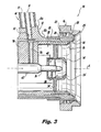
- combustor discharge air is directed into the inlet end 19 of nozzle body 12 and directed through a series of main and pilot air circuits or passages, which are shown in Fig. 3 .
- the air flowing through the main and pilot air circuits interacts with the main and pilot fuel flows from feed arm 14. That interaction facilitates the atomization of the main and pilot fuel issued from the outlet end 21 of nozzle body 12 and into the combustion chamber of the gas turbine engine.
- nozzle body 12 includes a main fuel atomizer 25 that has an outer air cap 16 and a main outer air swirler 18.
- a main outer air circuit 20 is defined between the outer air cap 16 and the outer air swirler 18.
- Swirl vanes 22 are provided within the main outer air circuit 20, depending from outer air swirler 18, to impart an angular component of swirl to the pressurized combustor air flowing therethrough.
- An outer fuel prefilmer 24 is positioned radially inward of the outer air swirler 18 and a main fuel swirler 26 is positioned radially inward of the prefilmer 24.
- Prefilmer 24 has a diverging prefilming surface at the nozzle opening. As described in more detail herein below with reference to Figs. 5A and 5B , portions of the main and pilot fuel circuits are defined in the outer diametrical surfaces 24a and 26a of the prefilmer 24 and main fuel swirler 26, respectively.
- the main fuel circuit receives fuel from the inner feed tube 15 and delivers that fuel into an annular spin chamber 28 located at the aft end of the main fuel atomizer.
- the main fuel atomizer further includes a main inner air circuit 30 defined between the main fuel swirler 26 and a converging pilot air cap 32.
- Swirl vanes 34 are provided within main inner air circuit 30, depending from pilot air cap 32, to impart an angular component of swirl to the pressurized combustor air flowing therethrough. In operation, swirling air flowing from main outer air circuit 20 and main inner air circuit 30 impinge upon the fuel issuing from spin chamber 28, to promote atomization of the fuel.
- Nozzle body 12 further includes an axially located pilot fuel atomizer 35 that includes the converging pilot air cap 32 and a pilot outer air swirler 36.
- a pilot outer air circuit 38 is defined between pilot air cap 32 and pilot outer air swirler 36.
- Swirl vanes 40 are provided within pilot outer air circuit 38, depending from air swirler 36, to impart an angular component of swirl to the air flowing therethrough.
- a pilot fuel swirler 42 shown here by way of example, as a pressure swirl atomizer, is coaxially disposed within the pilot outer air swirler 36.
- the pilot fuel swirler 42 receives fuel from the pilot fuel circuit by way of the inner pilot fuel conduit 76 in support flange 78. Pilot fuel conduit 76 is oriented radially, or perpendicularly with respect to longitudinal axis A.
- Nozzle body 12 includes a tube mounting section 12a and an atomizer mounting section 12b of reduced outer diameter.
- Tube mounting section 12a includes radially projecting mounting appendage that defines a primary fuel bowl for receiving concentric fuel tubes 15 and 17 of feed arm 14.
- a central main bore 52 extends from the fuel bowl for communicating with inner/main fuel tube 15 to deliver fuel to the main fuel circuit.
- Dual pilot fuel bores (not shown, but see, e.g., bores 54a and 54b in Fig. 6 of the above-referenced U.S. Patent No. 7,506,510 ) communicate with and extend from the fuel bowl for delivering pilot/cooling fuel from outer/pilot fuel tube 17 to the pilot fuel circuit.
- FIG. 4A is a schematic representation of prefilmer 24 as if unrolled from its cylindrical form shown in Fig. 5A to show the fluid pathways schematically.
- Outer pilot fuel circuit 60 includes two generally J-shaped fuel circuit half-sections 60a and 60b and a central section 60c formed in surface 24a.
- Main fuel circuit 70 is also formed in outer diametrical surface 24a of outer prefilmer 24. Main fuel circuit 70 is located forward, i.e., toward inlet end 19 shown in Fig.
- the two pilot fuel circuit half-sections 60a and 60b consists of a central fuel distribution section 70a which distributes fuel to four feed channels 70b that terminate in twelve (12) axially extending exit sections 70c.
- the exit sections 70c provide fuel to exit ports that feed into spin chamber 28, which is shown in Fig. 3 .
- the outer pilot fuel circuit half-sections 60a and 60b receive fuel from the pilot fuel tube 17 (see Fig. 3 ) via the central section 60c. A portion of the pilot fuel provided by the fuel tube 17 is directed to an inner pilot fuel circuit 62, which is described below with reference to Figs. 4B and 5B , through port 63.
- Main fuel circuit 70 receives fuel from central fuel bore 52, by way of inner fuel tube 15, shown in Fig. 3 .
- inner pilot fuel circuit 62 is formed in the outer diametrical surface 26a of fuel swirler 26.
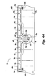
- Fig. 4B is a schematic representation of swirler 26 as if unrolled from its cylindrical form shown in Fig. 5B to show the fluid pathways schematically.
- the inner pilot fuel circuit 62 includes a central section 62c, which receives the pilot fuel from port 63 (see Fig. 4A ), and commonly terminating U-shaped channels 62a and 62b.
- the channels 62a and 62b are fed fuel from respective radial transfer ports 64a and 64b (see Fig. 4A ) associated with outer pilot fuel circuit half-sections 60a and 60b, respectively.
- Fuel from the channels 62a and 62b is directed to the pilot fuel swirler 42, shown in Fig. 3 , through an inner pilot fuel bore 67 formed in pilot atomizer support flange 78, which depends from the interior surface of fuel swirler 26.
- fuel traveling through the outer and inner pilot fuel circuits 60 and 62 is directed into thermal contact with the outer main fuel circuit 70, en route to the pilot fuel atomizer 35 located along the axis A of nozzle body 12.
- Each flow channel 62a and 62b includes a bend 82 therein extending from the junction with bore 67 to a point upstream of the junction.
- Each of channels 62a and 62b includes a respective flow splitter 80 in the respective bend 82 for swirling flow mitigation, as described in greater detail below with respect to Fig. 7 . While described in the exemplary context of having two channels at the junction, those skilled in the art will readily appreciate that any suitable number of channels can be included without departing from the spirit and scope of the invention.
- prefilmer 24 is joined outboard of swirler 26 by any suitable technique such as brazing.
- the fuel channels formed in the outer surfaces 24a and 26a are formed in a cylindrical region around the axis A shown in Fig. 1 .
- a prefilmer and swirler could be formed as an single integral component, such as by additive manufacturing techniques as described in the above-referenced U.S. Patent Application Serial No. 12/932,958 .
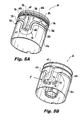
- FIG. 6 shows a fluid circuit, i.e., inner pilot fuel circuit 62, with two opposed channels 62a and 62b which are joined with a conduit 76 at a junction proximate inner pilot fuel bore 67.
- the flow arrows in Fig. 6 schematically indicate the swirling flow generated by this arrangement of channels, orifice, and conduit.
- Fig. 6 shows flow channels 62a and 62b without flow splitters 80 in order to describe the swirling flow effect.
- swirling flow indicated in Fig. 6 has the detrimental effect of lowering the effective flow number for the fluid circuit, effectively reducing the available flow area through conduit 76 (where flow number is mass flow rate in pounds-per-hour divided by the square-root of the pressure-drop in pounds-per-square-inch).
- Swirling flow creates a loss in useful (or useable) energy due to flow in non-desired directions, i.e. flow around a conduit rather than through the conduit, and ultimately acts like a blockage to reduce flow number.
- fluid circuits constructed in accordance with the subject invention include flow splitters 80 defined in each of the flow channels 62a and 62b proximate the respective outlet orifice, e.g., bore 67 leading to conduit 76.
- Each flow splitter 80 is configured and adapted to mitigate formation of swirling flow on fluids passing through the outlet orifice from the flow channels. As indicated schematically by flow arrows in Fig. 7 , each flow splitter 80 splits the flow in its respective channel going around the respective bend 82, reducing variation in pressure, velocity, and mass flow-rate in fluids approaching bore 67.
- flow splitters such as flow splitters 80 can help avoid flow separations around sharp turns in their respective flow channel.
- the effect of flow splitters 80 is that a strong swirl or vortex does not form at the junction with bore 67.
- flow splitters 80 reduce or eliminate swirling flow and the related pressure drop, effectively providing a higher flow number than would otherwise be provided.
- each flow splitter 80 includes an elongate flow splitter body dividing a portion of the respective flow channel into two branches 84a and 84b.
- the two branches 84a and 84b are substantially equal to one another in flow area, and the respective flow channel 62a or 62b has a flow area upstream of branches 84a and 84b that is substantially equal to that of the two branches 84a and 84b combined.
- Each flow splitter 80 is elongate in a longitudinal direction around bend 82 and has a substantially rectangular cross-section normal to the longitudinal direction along the length thereof. This can be accomplished by machining branches 84a and 84b out of surface 26a, for example.
- a gap e.g., 0.010 inches or more, can be provided between the flow splitters 80 and the inner surface of prefilmer 24, which can be advantageous in preventing a braze fillet from forming on the top of the splitters 80.
- the respective flow splitter 80 of each of the flow channels 62a and 62b extends longitudinally through a majority of the respective bend 82.
- Each flow splitter 80 should be spaced apart from the respective outlet orifice, e.g., bore 67, by a distance in a range of about 0.0 times to about 1.0 times the width of the outlet orifice, i.e., from no distance to about one outlet orifice diameter's distance, with no distance/spacing being the most effective for swirl mitigation. Swirling flow can be mitigated with distances outside this range, but generally, the effects of mitigating unwanted swirl diminish as this distance increases. This distance should be maintained to prevent the flows from the two branches 84a and 84b from fully rejoining into a single flow that could generate a swirling flow before passing into bore 67.
- each flow splitter 80 extends in a direction away from the outlet orifice to a distance that depends on the particular application. It is important that the upstream extent of flow splitters 80 be located upstream of or very near to where the channel turns from a straight run. In other words, flow splitters 80 should extend upstream of their respective bend 82 for the most effective swirl mitigation.
- the upstream end of a flow splitter 80 can be located downstream of the start of a bend 82, however the effectiveness is generally diminished. In applications where there is no bend 82 prior to a bore such as bore 67, a nominal flow splitter length of about twice the channel width should be used. Generally, the longer the flow splitter length, the more effective the flow splitter at mitigating unwanted swirl. In short, the flow splitters 80 should extend upstream far enough to split the flow at a point upstream of any potential swirl effects forming.
- branches 84a and 84b are dimensioned and configured to mitigate formation of swirling flow on fluids passing through the orifice even when flow is not even among the four branches 84a and 84b. This is the case even if one of the branches has a total flow blockage.
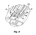
- Flow blockage 86 is shown in Fig. 8 completely blocking off flow through branch 84b of channel 62b. However, it has been demonstrated in conjunction with the subject invention that the remaining three branches 84a and 84b of channels 62a and 62b do not form a strongly swirling flow at bore 67. Rather, the flows from the three unblocked branches 84a and 84b enter conduit 76 as indicated schematically by flow arrows in Fig. 8 .
- Blockages such as blockage 86 can arise during the manufacture of an injector, such as by excess braze flowing into one of the branches 84a or 84b when joining fuel swirler 26 to prefilmer 24, or can result from debris or impurities in the fuel, or the like.
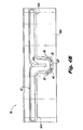
- FIG. 9 shows a portion of prefilmer 24 diametrically opposite bore 67 shown in Figs. 7 and 8 .
- the ends of the generally J-shaped fuel circuit half-sections 60a and 60b include radial transfer ports 64a and 64b, also shown in Fig. 4A , for allowing fuel to flow radially inward into channels 62a and 62b, shown in Figs. 4B and 5B .
- ports 64a and 64b are elongate and have a pill shape, rather than being simple circular bores. This elongate shape reduces swirling flow and therefore reduces pressure drop across the ports 64a and 64b.
- an outlet orifice such as ports 64a and 64b, can have any suitable shape that substantially deviates from a perfect circle, such as oblong or ovoid. Generally, the larger the aspect ratio of the non-circular orifice shape, the more effective the swirl mitigation.
- flow splitters such as flow splitters 80 could be positioned upstream of ports 64a and 64b to mitigate swirling flow, in which case the ports 64a and 64b could be circular or non-circular as described above.
- bore 67 and/or conduit 76 of Fig. 7 could be non-circular as described above to mitigate swirling flow therein.
- non-circular orifice/tube shapes and/or flow splitters can be used to mitigate swirling flow where flow channels have ports or radial passages therethrough, such as in radial ports 64a and 64b or as in bore 67 and conduit 76.
- flow mitigating features described herein can also be used for radially outward flow through a radial orifice.
- a portion of another exemplary embodiment of an injector 90 includes an integral swirler and prefilmer component 94, much like prefilmer 24 and swirler 26 described above, but formed as a single component. This can be accomplished, for example, by additive manufacturing techniques such as those described in the above-referenced U.S. Patent Application Serial No. 12/932,958 . Since component 94 is formed as a single, integral component, flow splitter 88 can extend across bore 96. Flow splitter 88 is generally similar to flow splitters 80 described above, but is a single elongate structure rather than two separate structures each stopping short of bore 67 as shown in Fig. 7 . This configuration enhances the maintenance of separate flows in each branch of channels 92 all the way to bore 96.
- the methods and apparatus described above are useful in reducing swirling flow and therefore pressure drop in flow geometries such as those described above. This can be particularly advantageous in applications such as pilot fuel circuits for fuel injectors in gas turbine engines where fuel staging requirements include pilot only operation at up to 60% or more of the maximum take-off thrust.
- Other advantages for fuel injector applications include the reduced likelihood of coking because of lower fuel temperatures that result from shorter fuel residence time in the fuel channels due to mitigation of regions of recirculating flow.
Landscapes
- Engineering & Computer Science (AREA)
- Chemical & Material Sciences (AREA)
- Combustion & Propulsion (AREA)
- Mechanical Engineering (AREA)
- General Engineering & Computer Science (AREA)
- Fuel-Injection Apparatus (AREA)
- Nozzles (AREA)
Abstract
Description
- This application is a continuation-in-part of
U.S. Patent Application Serial No. 12/932,958, filed March 10, 2011 - The present invention relates to fuel injection, and more particularly to mitigation of swirling flow in fuel passages of fuel injectors.
- Staged fuel injectors for gas turbine engines are well known in the art. They typically include a pilot fuel atomizer for use during engine ignition and low power engine operation, and at least one main fuel atomizer for use during high power engine operation. One difficulty associated with operating a staged fuel injector is that when the pilot fuel circuit is operating alone during low power operation, stagnant fuel located within the main fuel circuit can be susceptible to carbon formation or coking due to the temperatures associated with the operating environment. This can degrade engine performance over time.
- To address these difficulties, efforts have been made to actively cool a staged fuel injector using the fuel flow from the pilot fuel circuit.
U.S. Patent No. 7,506,510 , which is incorporated herein by reference in its entirety, discloses the use of active cooling to protect against carbon formation in the main fuel circuit of a staged airblast fuel injector. Increasingly, applications have emerged where the staging requirements include operation on pilot stage fuel at up to 60% of the maximum take-off thrust. This represents a substantial increase in the operational temperature for staged fuel injectors and tends to overheat the stagnant fuel in the unstaged main atomizer. In order to provide the additional cooling needed for such applications, the pilot fuel circuits have become increasingly intricate, which can lead to significant pilot stage pressure drop. - Such conventional methods and systems have generally been considered satisfactory for their intended purpose. However, there is still a need in the art for injectors that allow for increased pilot staging levels with improved pressure drop. There also remains a need in the art for such injectors that are easy to make and use. The present invention provides a solution for these problems.
- The subject invention is directed to a new and useful fluid circuit. The fluid circuit includes a plurality of inlet flow channels configured for passage of fluids therethrough. The flow channels join one another at a junction with an outlet orifice. A flow splitter is defined in each of the flow channels proximate the outlet orifice. Each flow splitter is configured and adapted to mitigate formation of swirling flow on fluids passing through the outlet orifice from the flow channels.
- In certain embodiments, there are two flow channels opposed to one another at the junction, however any suitable number of flow channels can be used. The flow splitter of each of the two flow channels can include an elongate flow splitter body dividing a portion of the respective flow channel into two branches and the two branches of each flow channel can be substantially equal to one another in flow area. The respective flow channel can have a flow area upstream of the two branches that is substantially equal to that of the two branches combined. The four branches can be dimensioned and configured to mitigate formation of swirling flow on fluids passing through the orifice even when one of the branches has a flow blockage.
- It is contemplated that each flow splitter can be elongate in a longitudinal direction and can have a substantially rectangular cross-section normal to a longitudinal direction along the length thereof. Each flow channel can include a bend therein extending from the junction to a point upstream of the junction. The respective flow splitter of each of the flow channels can extend longitudinally through a majority of the bend in the respective flow channel. Each flow splitter can be spaced apart from the outlet orifice by a distance in a range of about 0.0 times to about 1.0 times the width of the outlet orifice. Each flow splitter can extend in a direction away from the outlet orifice to a point upstream of a bend in the respective channel. It is also contemplated that the outlet orifice can have a shape that substantially deviates from a perfect circle.
- The invention also provides an injector having an injector body that defines a longitudinal axis. A fluid circuit is defined in the injector body. The fluid circuit includes a flow channel defined in a cylindrical region around the longitudinal axis. The fluid circuit is in fluid communication with an orifice for passage of fluids out from the flow channel into a radial direction with respect to the longitudinal axis. A flow splitter as described above is defined in the flow channel proximate the orifice. The fluid circuit can include first and second flow channels opposed to one another at a junction with the orifice, as described above. The flow splitter can be integral with the injector body.
- The invention also provides a staged fuel injector. The staged fuel injector includes a main fuel circuit for delivering fuel to a main fuel atomizer. The main fuel atomizer includes a radially outer prefilmer and a radially inner fuel swirler, wherein portions of the main fuel circuit are formed in the prefilmer. A pilot fuel circuit is included for delivering fuel to a pilot fuel atomizer which is located radially inward of the main fuel atomizer. The pilot fuel circuit includes a plurality of flow channels defined in the prefilmer and the fuel swirler. The pilot fuel circuit also includes a conduit for conveying fuel from the flow channels to the pilot fuel atomizer. The conduit is in fluid communication with the flow channels at an orifice. A flow splitter is defined in each of the flow channels proximate the orifice. Each flow splitter is configured and adapted to mitigate formation of swirling flow on fluids passing through the orifice from the flow channels into the conduit.
- In certain embodiments, a portion of each flow channel of the pilot fuel circuit defined in the radially outer prefilmer is in fluid communication with a portion of the respective flow channel defined in the radially inner fuel swirler by way of a radial passage. The radial passage can be circular or can have a non-circular cross-sectional shape selected from the group consisting of pill-shaped, oblong, ovoid, or any other suitable non-circular shape. The flow channel upstream of the radial passage can include a flow splitter configured and adapted to mitigate formation of swirling flow on fluids passing through the radial passage. The radially outer prefilmer, the radially inner fuel swirler, and the flow splitters can be integral with one another. It is also contemplated that the flow splitters can be integral with the radially inner fuel swirler, which can be joined together with the radially outer prefilmer at a braze joint. If a given channel is wide enough, two or more flow splitters can be included in the channel side by side without departing from the spirit and scope of the invention.
- These and other features of the systems and methods of the subject invention will become more readily apparent to those skilled in the art from the following detailed description of the preferred embodiments taken in conjunction with the drawings.
- So that those skilled in the art to which the subject invention appertains will readily understand how to make and use the devices and methods of the subject invention without undue experimentation, preferred embodiments thereof will be described in detail herein below with reference to certain figures, wherein:
-
Fig. 1 is a perspective view of an exemplary embodiment of a staged fuel injector constructed in accordance with the present invention, showing the spray outlet; -
Fig. 2 is a perspective view of the injector ofFig. 1 , showing the inlet end portion of the injector; -
Fig. 3 is a cross-sectional side elevation view of the injector ofFig. 1 , showing the fuel and air circuits for the main and pilot fuel stages; -
Fig. 4A is a schematic view of the main prefilmer portion of the injector ofFig. 1 , showing the fuel passages formed in the radially outer surface thereof; -
Fig. 4B is a schematic view of the main fuel swirler portion of the injector ofFig. 1 , showing the fuel passages formed in the radially outer surface thereof, including the flow splitters; -
Fig. 5A is a perspective view of the main prefilmer ofFig. 4A , showing the fuel passages formed in the radially outer surface thereof; -
Fig. 5B is a perspective view of the main fuel swirler ofFig. 4B , showing the fuel passages and flow splitters formed therein; -
Fig. 6 is a cut away perspective view of a portion of the injector ofFig. 1 , showing schematically the swirling flow resulting when there are no flow splitters proximate the bore leading to the pilot fuel atomizer; -
Fig. 7 is a cut away perspective view of a portion of the injector ofFig. 1 , showing the flow splitters, wherein the flow into the bore is shown schematically wherein the flow splitters mitigate the formation of swirling flows proximate the bore leading to the pilot fuel atomizer; -
Fig. 8 is a cut away perspective view of the portion of the injector ofFig. 7 , schematically showing the effects of a total blockage in one of the four branches of the fuel channels adjacent the flow splitters; -
Fig. 9 is a perspective view of a portion of the prefilmer ofFig. 5A , showing the pill-shaped radial ports for passage of fuel into the fuel channels of the fuel swirler; and -
Fig. 10 is a cut away perspective view of a portion of another exemplary embodiment of a staged fuel injector constructed in accordance with the subject invention, showing a single flow splitter extending over the bore leading to the pilot fuel atomizer. - Reference will now be made to the drawings wherein like reference numerals identify similar structural features or aspects of the subject invention. For purposes of explanation and illustration, and not limitation, a partial view of an exemplary embodiment of an injector in accordance with the invention is shown in
Fig. 1 and is designated generally byreference character 10. Other embodiments of injectors in accordance with the invention, or aspects thereof, are provided inFigs. 2-10 , as will be described. The systems and methods of the invention can be used to reduce pressure loss by mitigating swirling flow in flow channels, such as in fuel injectors for gas turbine engines. - Referring now to
Fig. 1 ,fuel injector 10 is adapted and configured for delivering fuel to the combustion chamber of a gas turbine engine.Fuel injector 10 is generally referred to as a staged fuel injector in that it includes a pilot fuel circuit, which typically operates during engine ignition and at low engine power and a main fuel circuit, which typically operates at high engine power (e.g., at take-off and cruise) and is typically staged off at lower power operation. -
Fuel injector 10 includes a generallycylindrical nozzle body 12, which depends from an elongated feed arm 14, and defines a longitudinal axis A. In operation, main and pilot fuel is delivered intonozzle body 12 through concentric fuel feed tubes. As shown inFig. 3 , these feed tubes include an inner/main fuel feed tube 15 and an outer/pilot fuel feed tube 17 located within the feed arm 14. Although not depicted herein, it is envisioned that the fuel feed tubes could be enclosed within an elongated shroud or protective strut extending from a fuel fitting to the nozzle body. - Referring now to
Fig. 2 , at the same time fuel is delivered tonozzle body 12 through feed arm 14, pressurized combustor discharge air is directed into the inlet end 19 ofnozzle body 12 and directed through a series of main and pilot air circuits or passages, which are shown inFig. 3 . The air flowing through the main and pilot air circuits interacts with the main and pilot fuel flows from feed arm 14. That interaction facilitates the atomization of the main and pilot fuel issued from the outlet end 21 ofnozzle body 12 and into the combustion chamber of the gas turbine engine. - Referring now to
Fig. 3 ,nozzle body 12 includes a main fuel atomizer 25 that has anouter air cap 16 and a mainouter air swirler 18. A mainouter air circuit 20 is defined between theouter air cap 16 and theouter air swirler 18.Swirl vanes 22 are provided within the mainouter air circuit 20, depending fromouter air swirler 18, to impart an angular component of swirl to the pressurized combustor air flowing therethrough. - An
outer fuel prefilmer 24 is positioned radially inward of theouter air swirler 18 and amain fuel swirler 26 is positioned radially inward of theprefilmer 24.Prefilmer 24 has a diverging prefilming surface at the nozzle opening. As described in more detail herein below with reference toFigs. 5A and 5B , portions of the main and pilot fuel circuits are defined in the outerdiametrical surfaces prefilmer 24 andmain fuel swirler 26, respectively. - With continuing reference to
Fig. 3 , the main fuel circuit receives fuel from the inner feed tube 15 and delivers that fuel into an annular spin chamber 28 located at the aft end of the main fuel atomizer. The main fuel atomizer further includes a main inner air circuit 30 defined between themain fuel swirler 26 and a convergingpilot air cap 32.Swirl vanes 34 are provided within main inner air circuit 30, depending frompilot air cap 32, to impart an angular component of swirl to the pressurized combustor air flowing therethrough. In operation, swirling air flowing from mainouter air circuit 20 and main inner air circuit 30 impinge upon the fuel issuing from spin chamber 28, to promote atomization of the fuel. -
Nozzle body 12 further includes an axially locatedpilot fuel atomizer 35 that includes the convergingpilot air cap 32 and a pilotouter air swirler 36. A pilot outer air circuit 38 is defined betweenpilot air cap 32 and pilotouter air swirler 36. Swirl vanes 40 are provided within pilot outer air circuit 38, depending fromair swirler 36, to impart an angular component of swirl to the air flowing therethrough. Apilot fuel swirler 42, shown here by way of example, as a pressure swirl atomizer, is coaxially disposed within the pilotouter air swirler 36. Thepilot fuel swirler 42 receives fuel from the pilot fuel circuit by way of the innerpilot fuel conduit 76 insupport flange 78.Pilot fuel conduit 76 is oriented radially, or perpendicularly with respect to longitudinal axis A. -
Nozzle body 12 includes atube mounting section 12a and an atomizer mounting section 12b of reduced outer diameter.Tube mounting section 12a includes radially projecting mounting appendage that defines a primary fuel bowl for receiving concentric fuel tubes 15 and 17 of feed arm 14. A centralmain bore 52 extends from the fuel bowl for communicating with inner/main fuel tube 15 to deliver fuel to the main fuel circuit. Dual pilot fuel bores (not shown, but see, e.g., bores 54a and 54b inFig. 6 of the above-referencedU.S. Patent No. 7,506,510 ) communicate with and extend from the fuel bowl for delivering pilot/cooling fuel from outer/pilot fuel tube 17 to the pilot fuel circuit. - Referring now to
Figs. 4A and4B , the outerdiametrical surface 24a ofouter prefilmer 24 and the outerdiametrical surface 26a ofmain fuel swirler 26 include channels or grooves that form portions of the main and pilot fuel circuits or pathways.Fig. 4A is a schematic representation ofprefilmer 24 as if unrolled from its cylindrical form shown inFig. 5A to show the fluid pathways schematically. Outerpilot fuel circuit 60 includes two generally J-shaped fuel circuit half-sections surface 24a.Main fuel circuit 70 is also formed in outerdiametrical surface 24a ofouter prefilmer 24.Main fuel circuit 70 is located forward, i.e., toward inlet end 19 shown inFig. 2 , of the two pilot fuel circuit half-sections fuel distribution section 70a which distributes fuel to fourfeed channels 70b that terminate in twelve (12) axially extendingexit sections 70c. As discussed in the above-referencedU.S. Patent Application Serial No. 12/932,958 , theexit sections 70c provide fuel to exit ports that feed into spin chamber 28, which is shown inFig. 3 . The outer pilot fuel circuit half-sections Fig. 3 ) via the central section 60c. A portion of the pilot fuel provided by the fuel tube 17 is directed to an innerpilot fuel circuit 62, which is described below with reference toFigs. 4B and5B , throughport 63.Main fuel circuit 70 receives fuel from central fuel bore 52, by way of inner fuel tube 15, shown inFig. 3 . - Referring now to
Figs. 4B and5B , innerpilot fuel circuit 62 is formed in the outerdiametrical surface 26a offuel swirler 26.Fig. 4B is a schematic representation ofswirler 26 as if unrolled from its cylindrical form shown inFig. 5B to show the fluid pathways schematically. The innerpilot fuel circuit 62 includes acentral section 62c, which receives the pilot fuel from port 63 (seeFig. 4A ), and commonly terminatingU-shaped channels central section 62c, thechannels radial transfer ports 64a and 64b (seeFig. 4A ) associated with outer pilot fuel circuit half-sections channels pilot fuel swirler 42, shown inFig. 3 , through an inner pilot fuel bore 67 formed in pilotatomizer support flange 78, which depends from the interior surface offuel swirler 26. As described in the above-referencedU.S. Patent Application Serial No. 12/932,958 , fuel traveling through the outer and innerpilot fuel circuits main fuel circuit 70, en route to thepilot fuel atomizer 35 located along the axis A ofnozzle body 12. Eachflow channel bend 82 therein extending from the junction with bore 67 to a point upstream of the junction. Each ofchannels respective flow splitter 80 in therespective bend 82 for swirling flow mitigation, as described in greater detail below with respect toFig. 7 . While described in the exemplary context of having two channels at the junction, those skilled in the art will readily appreciate that any suitable number of channels can be included without departing from the spirit and scope of the invention. - Referring now to
Fig. 6 ,prefilmer 24 is joined outboard ofswirler 26 by any suitable technique such as brazing. In this manner, the fuel channels formed in theouter surfaces Fig. 1 . It is also contemplated that a prefilmer and swirler could be formed as an single integral component, such as by additive manufacturing techniques as described in the above-referencedU.S. Patent Application Serial No. 12/932,958 . - It has been discovered in conjunction with the subject invention that in fluid circuits having a junction of flow channels such as the junction of
channels Fig. 6 shows a fluid circuit, i.e., innerpilot fuel circuit 62, with twoopposed channels conduit 76 at a junction proximate inner pilot fuel bore 67. The flow arrows inFig. 6 schematically indicate the swirling flow generated by this arrangement of channels, orifice, and conduit.Fig. 6 showsflow channels flow splitters 80 in order to describe the swirling flow effect. - Without wishing to be bound by theory, it is believed that for internal flow of liquids or gases, as the flow transitions from a channel to a hole or tube, which may be oriented perpendicular to the general incoming flow path, a swirling flow field can be established in the flow as it passes through the hole or tube. Relatively minor fluctuations or imbalances in the flow from channels meeting a hole or tube give rise to the swirling flow draining into the hole or tube. The swirling flow is stable, and it is believed that depending on the upstream fluctuations and/or imbalances, the swirl direction can vary to be clockwise or counter clockwise from circuit to circuit. Such swirling flows have been demonstrated with test hardware as well as with CFD modeling in conjunction with the subject invention.
- While there may be applications where swirling flow behavior is desirable, such as for increasing heat transfer or for a cyclone particle separator, the swirling flow indicated in
Fig. 6 has the detrimental effect of lowering the effective flow number for the fluid circuit, effectively reducing the available flow area through conduit 76 (where flow number is mass flow rate in pounds-per-hour divided by the square-root of the pressure-drop in pounds-per-square-inch). Swirling flow creates a loss in useful (or useable) energy due to flow in non-desired directions, i.e. flow around a conduit rather than through the conduit, and ultimately acts like a blockage to reduce flow number. This reduced flow number translates into pressure drop that exceeds predictions based on standard design techniques, i.e., standard design techniques do not account for the pressure drop due to the swirling flow effects described above. This swirl-related pressure drop becomes particularly significant in applications where a relatively high flow is required in the fluid circuit, such as in pilot stages of fuel injectors operating at 60% of the maximum take-off thrust with pilot stage fuel only. - Referring now to
Fig. 7 , in order to mitigate the swirling flow phenomenon described above, fluid circuits constructed in accordance with the subject invention includeflow splitters 80 defined in each of theflow channels conduit 76. Eachflow splitter 80 is configured and adapted to mitigate formation of swirling flow on fluids passing through the outlet orifice from the flow channels. As indicated schematically by flow arrows inFig. 7 , eachflow splitter 80 splits the flow in its respective channel going around therespective bend 82, reducing variation in pressure, velocity, and mass flow-rate influids approaching bore 67. In certain applications, flow splitters such asflow splitters 80 can help avoid flow separations around sharp turns in their respective flow channel. The effect offlow splitters 80 is that a strong swirl or vortex does not form at the junction withbore 67. In short,flow splitters 80 reduce or eliminate swirling flow and the related pressure drop, effectively providing a higher flow number than would otherwise be provided. - With continued reference to
Fig. 7 , eachflow splitter 80 includes an elongate flow splitter body dividing a portion of the respective flow channel into twobranches 84a and 84b. The twobranches 84a and 84b are substantially equal to one another in flow area, and therespective flow channel branches 84a and 84b that is substantially equal to that of the twobranches 84a and 84b combined. - Each
flow splitter 80 is elongate in a longitudinal direction aroundbend 82 and has a substantially rectangular cross-section normal to the longitudinal direction along the length thereof. This can be accomplished by machiningbranches 84a and 84b out ofsurface 26a, for example. A gap, e.g., 0.010 inches or more, can be provided between theflow splitters 80 and the inner surface ofprefilmer 24, which can be advantageous in preventing a braze fillet from forming on the top of thesplitters 80. Therespective flow splitter 80 of each of theflow channels respective bend 82. - Each
flow splitter 80 should be spaced apart from the respective outlet orifice, e.g., bore 67, by a distance in a range of about 0.0 times to about 1.0 times the width of the outlet orifice, i.e., from no distance to about one outlet orifice diameter's distance, with no distance/spacing being the most effective for swirl mitigation. Swirling flow can be mitigated with distances outside this range, but generally, the effects of mitigating unwanted swirl diminish as this distance increases. This distance should be maintained to prevent the flows from the twobranches 84a and 84b from fully rejoining into a single flow that could generate a swirling flow before passing intobore 67. - On the opposite end, namely the far end from
bore 67, eachflow splitter 80 extends in a direction away from the outlet orifice to a distance that depends on the particular application. It is important that the upstream extent offlow splitters 80 be located upstream of or very near to where the channel turns from a straight run. In other words, flowsplitters 80 should extend upstream of theirrespective bend 82 for the most effective swirl mitigation. The upstream end of aflow splitter 80 can be located downstream of the start of abend 82, however the effectiveness is generally diminished. In applications where there is nobend 82 prior to a bore such asbore 67, a nominal flow splitter length of about twice the channel width should be used. Generally, the longer the flow splitter length, the more effective the flow splitter at mitigating unwanted swirl. In short, theflow splitters 80 should extend upstream far enough to split the flow at a point upstream of any potential swirl effects forming. - Referring now to
Fig. 8 ,branches 84a and 84b are dimensioned and configured to mitigate formation of swirling flow on fluids passing through the orifice even when flow is not even among the fourbranches 84a and 84b. This is the case even if one of the branches has a total flow blockage.Flow blockage 86 is shown inFig. 8 completely blocking off flow through branch 84b ofchannel 62b. However, it has been demonstrated in conjunction with the subject invention that the remaining threebranches 84a and 84b ofchannels bore 67. Rather, the flows from the threeunblocked branches 84a and 84b enterconduit 76 as indicated schematically by flow arrows inFig. 8 . Thus even if one of the fourbranches 84a or 84b becomes completely blocked off, the total pilot fuel circuit flow can still be ample for a given application, and the overall flow is still better than if noflow splitters 80 are provided. Blockages such asblockage 86 can arise during the manufacture of an injector, such as by excess braze flowing into one of thebranches 84a or 84b when joiningfuel swirler 26 toprefilmer 24, or can result from debris or impurities in the fuel, or the like. - Referring now to
Fig. 9 , another manner of reducing swirling flow at a junction between a flow channel and an orifice in accordance with the subject invention involves the shape of the orifice itself.Fig. 9 shows a portion ofprefilmer 24 diametrically opposite bore 67 shown inFigs. 7 and8 . The ends of the generally J-shaped fuel circuit half-sections radial transfer ports 64a and 64b, also shown inFig. 4A , for allowing fuel to flow radially inward intochannels Figs. 4B and5B . There is a potential to form a swirling flow atports 64a and 64b, much as described above, even though the flow junction includes only one channel with a perpendicular port or orifice, rather than two opposed channels. However,ports 64a and 64b are elongate and have a pill shape, rather than being simple circular bores. This elongate shape reduces swirling flow and therefore reduces pressure drop across theports 64a and 64b. It is also contemplated that in accordance with the subject invention an outlet orifice, such asports 64a and 64b, can have any suitable shape that substantially deviates from a perfect circle, such as oblong or ovoid. Generally, the larger the aspect ratio of the non-circular orifice shape, the more effective the swirl mitigation. In other words, the more eccentric an elliptical orifice is, or the larger the width to length ratio is for a pill shaped orifice, for example, the more effective the orifice is at mitigating swirl. It is also contemplated that flow splitters such asflow splitters 80 could be positioned upstream ofports 64a and 64b to mitigate swirling flow, in which case theports 64a and 64b could be circular or non-circular as described above. Additionally, it is also contemplated that in addition to or in lieu offlow splitters 80, bore 67 and/orconduit 76 ofFig. 7 could be non-circular as described above to mitigate swirling flow therein. In short, non-circular orifice/tube shapes and/or flow splitters can be used to mitigate swirling flow where flow channels have ports or radial passages therethrough, such as inradial ports 64a and 64b or as inbore 67 andconduit 76. Moreover, while described herien in the exemplary context of radially inward flow through a radial orifice, those skilled in the art will readily appreciate that the flow mitigating features described herein can also be used for radially outward flow through a radial orifice. - With reference now to
Fig. 10 , a portion of another exemplary embodiment of an injector 90 includes an integral swirler andprefilmer component 94, much likeprefilmer 24 andswirler 26 described above, but formed as a single component. This can be accomplished, for example, by additive manufacturing techniques such as those described in the above-referencedU.S. Patent Application Serial No. 12/932,958 . Sincecomponent 94 is formed as a single, integral component, flow splitter 88 can extend across bore 96. Flow splitter 88 is generally similar to flowsplitters 80 described above, but is a single elongate structure rather than two separate structures each stopping short ofbore 67 as shown inFig. 7 . This configuration enhances the maintenance of separate flows in each branch ofchannels 92 all the way to bore 96. - While described above in the exemplary context of having a single flow splitter dividing a flow channel into two branches, those skilled in the art will readily appreciate that any suitable number of flow splitters can be included, dividing a flow channel into any suitable number of branches without departing from the spirit and scope of the invention. It is possible to gain at least some swirl mitigation benefits, even if only one of two opposed flow channels includes one or more flow splitters. Additionally, in applications where there is only one flow channel, rather than two opposed flow channels, leading up to a bore, one or more flow splitters in the channel can provide significant swirl mitigation, without departing from the spirit and scope of the invention.
- The exemplary embodiments described above show applications where flow channels have bores or conduits joining them at a perpendicular orientation, however those skilled in the art will readily appreciate that oblique angles for the bores or conduits can also be used without departing from the spirit and scope of the invention. Moreover, while described in the exemplary context of fuel flow in fuel injectors, those skilled in the art will readily appreciate that the features of the invention described above can readily be used in any other suitable application without departing from the spirit and scope of the invention.
- The methods and apparatus described above are useful in reducing swirling flow and therefore pressure drop in flow geometries such as those described above. This can be particularly advantageous in applications such as pilot fuel circuits for fuel injectors in gas turbine engines where fuel staging requirements include pilot only operation at up to 60% or more of the maximum take-off thrust. Other advantages for fuel injector applications include the reduced likelihood of coking because of lower fuel temperatures that result from shorter fuel residence time in the fuel channels due to mitigation of regions of recirculating flow.
- The methods and systems of the present invention, as described above and shown in the drawings, provide for fluid circuits, such as in injectors, with superior properties including improved pressure drop through swirling flow mitigation. While the apparatus and methods of the subject invention have been shown and described with reference to preferred embodiments, those skilled in the art will readily appreciate that changes and/or modifications may be made thereto without departing from the spirit and scope of the subject invention.
Claims (15)
- A fluid circuit comprising:a) a plurality of inlet flow channels configured for passage of fluids therethrough,
wherein the flow channels join one another at a junction with an outlet orifice; andb) a flow splitter defined in each of the flow channels proximate the outlet orifice, each flow splitter being configured and adapted to mitigate formation of swirling flow on fluids passing through the outlet orifice from the flow channels. - A fluid circuit as recited in claim 1, wherein there are two flow channels opposed to one another at the junction, and wherein the flow splitter of each of the two flow channels includes an elongate flow splitter body dividing a portion of the respective flow channel into two branches, and
optionally:-
the two branches of each flow channel are substantially equal to one another in flow area. - A fluid circuit as recited in claim 1, wherein at least one of c) and d):-c) the flow splitter of each of the flow channels includes an elongate flow splitter body dividing a portion of the respective flow channel into two branches, wherein the respective flow channel has a flow area upstream of the two branches that is substantially equal to that of the two branches combined;d) each flow splitter is elongate in a longitudinal direction and has a substantially rectangular cross-section normal to a longitudinal direction along the length thereof.
- A fluid circuit as recited in claim 1, wherein at least one of c) and d):-c) there are two flow channels opposed to one another at the junction, and wherein the flow splitter of each of the two flow channels includes an elongate flow splitter body dividing a portion of the respective flow channel into two branches, and wherein the four branches are dimensioned and configured to mitigate formation of swirling flow on fluids passing through the orifice even when one of the branches has a flow blockage;d) there are two flow channels opposed to one another at the junction, wherein each flow channel includes a bend therein extending from the junction to a point upstream of the junction, and wherein the respective flow splitter of each of the two flow channels extends longitudinally through a majority of the bend in the respective flow channel.
- A fluid circuit as recited in claim 1, wherein at least one of:-c) each flow splitter is spaced apart from the outlet orifice by a distance in a range of about 0.0 times to about 1.0 times the width of the outlet orifice;d) each flow splitter extends in a direction away from the outlet orifice to a point upstream of a bend in the respective channel.
- A fluid circuit as recited in claim 1, wherein the outlet orifice has a shape that substantially deviates from a perfect circle.
- An injector comprising:a) an injector body defining a longitudinal axis;b) a fluid circuit defined in the injector body, the fluid circuit including a flow channel defined in a cylindrical region around the longitudinal axis and being in fluid communication with an orifice for passage of fluids out from the flow channel into a radial direction with respect to the longitudinal axis; andc) a flow splitter defined in the flow channel proximate the orifice, the flow splitter being configured and adapted to mitigate formation of swirling flow on fluids passing through the orifice from the flow channel.
- An injector as recited in claim 7, wherein the flow channel is a first flow channel and the flow splitter is a first flow splitter, wherein the fluid circuit includes a second flow channel defined in the cylindrical region around the longitudinal axis of the injector body, wherein a second flow splitter is defined in the second flow channel proximate the orifice, and wherein the first and second flow channels oppose one another at a junction with the orifice, and wherein the flow splitter of each of the two flow channels includes an elongate flow splitter body dividing a portion of the respective flow channel into two branches.
- A fluid circuit as recited in claim 7, wherein the flow channel is a first flow channel and the flow splitter is a first flow splitter, wherein the fluid circuit includes a second flow channel defined in the cylindrical region around the longitudinal axis of the injector body, wherein a second flow splitter is defined in the second flow channel proximate the orifice, wherein the first and second flow channels oppose one another at a junction with the orifice, wherein each flow channel includes a bend therein extending from the junction to a point upstream of the junction, and wherein the respective flow splitter of each of the two flow channels extends longitudinally through a majority of the bend in the respective flow channel.
- An injector as recited in claim 7, wherein the flow splitter is integral with the injector body.
- A staged fuel injector comprising:a) a main fuel circuit for delivering fuel to a main fuel atomizer, the main fuel atomizer including a radially outer prefilmer and a radially inner fuel swirler, wherein portions of the main fuel circuit are formed in the prefilmer;b) a pilot fuel circuit for delivering fuel to a pilot fuel atomizer which is located radially inward of the main fuel atomizer, wherein the pilot fuel circuit includes a plurality of flow channels defined in the prefilmer and the fuel swirler, the pilot fuel circuit further including a conduit for conveying fuel from the flow channels to the pilot fuel atomizer, wherein the conduit is in fluid communication with the flow channels at an orifice; andc) a flow splitter defined in each of the flow channels proximate the orifice, each flow splitter being configured and adapted to mitigate formation of swirling flow on fluids passing through the orifice from the flow channels into the conduit.
- A staged fuel injector as recited in claim 11, wherein at least one of d) and e):-d) a portion of each flow channel of the pilot fuel circuit defined in the radially outer prefilmer is in fluid communication with a portion of the respective flow channel defined in the radially inner fuel swirler by way of a radial passage, wherein the flow channel upstream of the radial passage includes a flow splitter configured and adapted to mitigate formation of swirling flow on fluids passing through the radial passage;e) the radially outer prefilmer, the radially inner fuel swirler, and the flow splitters are integral with one another.
- A staged fuel injector as recited in claim 11, wherein at least one of d) and e):-d) the flow splitters are integral with the radially inner fuel swirler, and wherein the radially inner fuel swirler and the radially outer prefilmer are joined together at a braze joint;e) there are two flow channels of the pilot fuel circuit defined in the radially inner fuel swirler that are opposed to one another at a junction with the conduit to the pilot fuel atomizer, and wherein the flow splitter of each of the two flow channels includes an elongate flow splitter body dividing a portion of the respective flow channel into two branches.
- An injector comprising:a) an injector body defining a longitudinal axis; andb) a fluid circuit defined in the injector body, the fluid circuit including a flow channel defined in a cylindrical region around the longitudinal axis and being in fluid communication with an orifice for passage of fluids out from the flow channel into a radial direction with respect to the longitudinal axis, wherein the orifice has a shape that substantially deviates from a perfect circle to mitigate formation of swirling flow on fluids passing through the orifice from the flow channel.
- An injector as recited in claim 14, wherein the orifice has a cross-sectional shape selected from the group consisting of pill-shaped, oblong, ovoid, and circular.
Applications Claiming Priority (1)
| Application Number | Priority Date | Filing Date | Title |
|---|---|---|---|
| US13/235,125 US20120227408A1 (en) | 2011-03-10 | 2011-09-16 | Systems and methods of pressure drop control in fluid circuits through swirling flow mitigation |
Publications (3)
| Publication Number | Publication Date |
|---|---|
| EP2570727A2 true EP2570727A2 (en) | 2013-03-20 |
| EP2570727A3 EP2570727A3 (en) | 2015-12-23 |
| EP2570727B1 EP2570727B1 (en) | 2019-05-22 |
Family
ID=46758637
Family Applications (1)
| Application Number | Title | Priority Date | Filing Date |
|---|---|---|---|
| EP12182739.8A Active EP2570727B1 (en) | 2011-09-16 | 2012-09-03 | Injector for pressure drop control in fluid circuits through swirling flow mitigation |
Country Status (1)
| Country | Link |
|---|---|
| EP (1) | EP2570727B1 (en) |
Cited By (5)
| Publication number | Priority date | Publication date | Assignee | Title |
|---|---|---|---|---|
| EP2626626A3 (en) * | 2012-02-08 | 2013-09-11 | Delavan Inc. | Improved liquid fuel swirler |
| EP3049703A4 (en) * | 2013-09-27 | 2017-06-28 | United Technologies Corporation | Fuel/oil manifold |
| US11168887B2 (en) | 2019-09-26 | 2021-11-09 | Rolls-Royce Plc | Fuel spray nozzle |
| CN114754378A (en) * | 2022-06-13 | 2022-07-15 | 成都中科翼能科技有限公司 | Gas turbine combustor structure |
| EP4239248A1 (en) | 2022-03-01 | 2023-09-06 | Rolls-Royce plc | Fuel spray nozzle |
Citations (1)
| Publication number | Priority date | Publication date | Assignee | Title |
|---|---|---|---|---|
| US7506510B2 (en) | 2006-01-17 | 2009-03-24 | Delavan Inc | System and method for cooling a staged airblast fuel injector |
Family Cites Families (4)
| Publication number | Priority date | Publication date | Assignee | Title |
|---|---|---|---|---|
| DE1008068B (en) * | 1953-06-05 | 1957-05-09 | Benno Schilde Maschb A G | Device for deflecting and evenly distributing a flowing medium |
| US5767384A (en) * | 1995-08-30 | 1998-06-16 | Hewlett-Packard Company | System for developing laminar flow |
| JP2003148710A (en) * | 2001-11-14 | 2003-05-21 | Mitsubishi Heavy Ind Ltd | Combustor |
| US7299997B2 (en) * | 2003-10-27 | 2007-11-27 | Siemens Vdo Automotive Corporation | Fuel injector with sauter-mean-diameter atomization spray of less than 70 microns |
-
2012
- 2012-09-03 EP EP12182739.8A patent/EP2570727B1/en active Active
Patent Citations (1)
| Publication number | Priority date | Publication date | Assignee | Title |
|---|---|---|---|---|
| US7506510B2 (en) | 2006-01-17 | 2009-03-24 | Delavan Inc | System and method for cooling a staged airblast fuel injector |
Cited By (7)
| Publication number | Priority date | Publication date | Assignee | Title |
|---|---|---|---|---|
| EP2626626A3 (en) * | 2012-02-08 | 2013-09-11 | Delavan Inc. | Improved liquid fuel swirler |
| EP3049703A4 (en) * | 2013-09-27 | 2017-06-28 | United Technologies Corporation | Fuel/oil manifold |
| US10513983B2 (en) | 2013-09-27 | 2019-12-24 | United Technologies Corporation | Fuel/oil manifold |
| US11168887B2 (en) | 2019-09-26 | 2021-11-09 | Rolls-Royce Plc | Fuel spray nozzle |
| EP4239248A1 (en) | 2022-03-01 | 2023-09-06 | Rolls-Royce plc | Fuel spray nozzle |
| CN114754378A (en) * | 2022-06-13 | 2022-07-15 | 成都中科翼能科技有限公司 | Gas turbine combustor structure |
| CN114754378B (en) * | 2022-06-13 | 2022-08-19 | 成都中科翼能科技有限公司 | Gas turbine combustor structure |
Also Published As
| Publication number | Publication date |
|---|---|
| EP2570727A3 (en) | 2015-12-23 |
| EP2570727B1 (en) | 2019-05-22 |
Similar Documents
| Publication | Publication Date | Title |
|---|---|---|
| US20120227408A1 (en) | Systems and methods of pressure drop control in fluid circuits through swirling flow mitigation | |
| EP2923150B1 (en) | Anti-coking liquid fuel cartridge | |
| JP6708380B2 (en) | Combustion turbine engine fuel injector assembly | |
| EP2570727B1 (en) | Injector for pressure drop control in fluid circuits through swirling flow mitigation | |
| JP4689777B2 (en) | Two types of fuel nozzle | |
| US8024932B1 (en) | System and method for a combustor nozzle | |
| EP3074697B1 (en) | Fuel nozzle with fluid lock and purge apparatus | |
| EP3156732B1 (en) | Airblast fuel injectors | |
| US20140291418A1 (en) | Multi-circuit airblast fuel nozzle | |
| EP3348908B1 (en) | Gas turbine fuel injector | |
| US9488108B2 (en) | Radial vane inner air swirlers | |
| GB2434637A (en) | A Staged Fuel Injector | |
| GB2457807A (en) | Fuel Injector Feed Arm with Central Secondary Fuel Flow Passage | |
| US20120228405A1 (en) | Liquid swirler flow control | |
| US10967394B2 (en) | Fluid atomizer | |
| JP2011163753A (en) | Fuel injector nozzle | |
| US10094352B2 (en) | Swirl impingement prefilming | |
| US20220412550A1 (en) | Swirler-ferrule assembly | |
| JP3826196B2 (en) | Pre-filmer type air blast atomization nozzle | |
| EP3336434A1 (en) | Dual fuel radial flow nozzles for a gas turbine | |
| US20160047315A1 (en) | Atomizing fuel nozzle | |
| RU2721627C2 (en) | Fuel injector with gas distribution through plurality of tubes | |
| EP3348906B1 (en) | Gas turbine fuel injector | |
| US9605594B2 (en) | Injection device for a turbine engine combustion chamber | |
| EP3531022B1 (en) | Fuel injectors including gas fuel injection |
Legal Events
| Date | Code | Title | Description |
|---|---|---|---|
| PUAI | Public reference made under article 153(3) epc to a published international application that has entered the european phase |
Free format text: ORIGINAL CODE: 0009012 |
|
| 17P | Request for examination filed |
Effective date: 20120903 |
|
| AK | Designated contracting states |
Kind code of ref document: A2 Designated state(s): AL AT BE BG CH CY CZ DE DK EE ES FI FR GB GR HR HU IE IS IT LI LT LU LV MC MK MT NL NO PL PT RO RS SE SI SK SM TR |
|
| AX | Request for extension of the european patent |
Extension state: BA ME |
|
| RAP1 | Party data changed (applicant data changed or rights of an application transferred) |
Owner name: ROLLS-ROYCE PLC |
|
| RAP1 | Party data changed (applicant data changed or rights of an application transferred) |
Owner name: ROLLS-ROYCE PLC |
|
| PUAL | Search report despatched |
Free format text: ORIGINAL CODE: 0009013 |
|
| AK | Designated contracting states |
Kind code of ref document: A3 Designated state(s): AL AT BE BG CH CY CZ DE DK EE ES FI FR GB GR HR HU IE IS IT LI LT LU LV MC MK MT NL NO PL PT RO RS SE SI SK SM TR |
|
| AX | Request for extension of the european patent |
Extension state: BA ME |
|
| RIC1 | Information provided on ipc code assigned before grant |
Ipc: F23R 3/28 20060101ALI20151116BHEP Ipc: F23R 3/34 20060101ALI20151116BHEP Ipc: F23R 3/14 20060101AFI20151116BHEP Ipc: F15D 1/00 20060101ALI20151116BHEP Ipc: F02C 7/22 20060101ALI20151116BHEP |
|
| STAA | Information on the status of an ep patent application or granted ep patent |
Free format text: STATUS: EXAMINATION IS IN PROGRESS |
|
| 17Q | First examination report despatched |
Effective date: 20180622 |
|
| GRAP | Despatch of communication of intention to grant a patent |
Free format text: ORIGINAL CODE: EPIDOSNIGR1 |
|
| STAA | Information on the status of an ep patent application or granted ep patent |
Free format text: STATUS: GRANT OF PATENT IS INTENDED |
|
| GRAS | Grant fee paid |
Free format text: ORIGINAL CODE: EPIDOSNIGR3 |
|
| INTG | Intention to grant announced |
Effective date: 20190321 |
|
| GRAA | (expected) grant |
Free format text: ORIGINAL CODE: 0009210 |
|
| STAA | Information on the status of an ep patent application or granted ep patent |
Free format text: STATUS: THE PATENT HAS BEEN GRANTED |
|
| AK | Designated contracting states |
Kind code of ref document: B1 Designated state(s): AL AT BE BG CH CY CZ DE DK EE ES FI FR GB GR HR HU IE IS IT LI LT LU LV MC MK MT NL NO PL PT RO RS SE SI SK SM TR |
|
| REG | Reference to a national code |
Ref country code: GB Ref legal event code: FG4D |
|
| REG | Reference to a national code |
Ref country code: CH Ref legal event code: EP |
|
| REG | Reference to a national code |
Ref country code: IE Ref legal event code: FG4D |
|
| REG | Reference to a national code |
Ref country code: DE Ref legal event code: R096 Ref document number: 602012060308 Country of ref document: DE |
|
| REG | Reference to a national code |
Ref country code: AT Ref legal event code: REF Ref document number: 1136569 Country of ref document: AT Kind code of ref document: T Effective date: 20190615 |
|
| REG | Reference to a national code |
Ref country code: NL Ref legal event code: MP Effective date: 20190522 |
|
| REG | Reference to a national code |
Ref country code: LT Ref legal event code: MG4D |
|
| PG25 | Lapsed in a contracting state [announced via postgrant information from national office to epo] |
Ref country code: AL Free format text: LAPSE BECAUSE OF FAILURE TO SUBMIT A TRANSLATION OF THE DESCRIPTION OR TO PAY THE FEE WITHIN THE PRESCRIBED TIME-LIMIT Effective date: 20190522 Ref country code: ES Free format text: LAPSE BECAUSE OF FAILURE TO SUBMIT A TRANSLATION OF THE DESCRIPTION OR TO PAY THE FEE WITHIN THE PRESCRIBED TIME-LIMIT Effective date: 20190522 Ref country code: PT Free format text: LAPSE BECAUSE OF FAILURE TO SUBMIT A TRANSLATION OF THE DESCRIPTION OR TO PAY THE FEE WITHIN THE PRESCRIBED TIME-LIMIT Effective date: 20190922 Ref country code: SE Free format text: LAPSE BECAUSE OF FAILURE TO SUBMIT A TRANSLATION OF THE DESCRIPTION OR TO PAY THE FEE WITHIN THE PRESCRIBED TIME-LIMIT Effective date: 20190522 Ref country code: FI Free format text: LAPSE BECAUSE OF FAILURE TO SUBMIT A TRANSLATION OF THE DESCRIPTION OR TO PAY THE FEE WITHIN THE PRESCRIBED TIME-LIMIT Effective date: 20190522 Ref country code: NO Free format text: LAPSE BECAUSE OF FAILURE TO SUBMIT A TRANSLATION OF THE DESCRIPTION OR TO PAY THE FEE WITHIN THE PRESCRIBED TIME-LIMIT Effective date: 20190822 Ref country code: HR Free format text: LAPSE BECAUSE OF FAILURE TO SUBMIT A TRANSLATION OF THE DESCRIPTION OR TO PAY THE FEE WITHIN THE PRESCRIBED TIME-LIMIT Effective date: 20190522 Ref country code: NL Free format text: LAPSE BECAUSE OF FAILURE TO SUBMIT A TRANSLATION OF THE DESCRIPTION OR TO PAY THE FEE WITHIN THE PRESCRIBED TIME-LIMIT Effective date: 20190522 Ref country code: LT Free format text: LAPSE BECAUSE OF FAILURE TO SUBMIT A TRANSLATION OF THE DESCRIPTION OR TO PAY THE FEE WITHIN THE PRESCRIBED TIME-LIMIT Effective date: 20190522 |
|
| PG25 | Lapsed in a contracting state [announced via postgrant information from national office to epo] |
Ref country code: RS Free format text: LAPSE BECAUSE OF FAILURE TO SUBMIT A TRANSLATION OF THE DESCRIPTION OR TO PAY THE FEE WITHIN THE PRESCRIBED TIME-LIMIT Effective date: 20190522 Ref country code: BG Free format text: LAPSE BECAUSE OF FAILURE TO SUBMIT A TRANSLATION OF THE DESCRIPTION OR TO PAY THE FEE WITHIN THE PRESCRIBED TIME-LIMIT Effective date: 20190822 Ref country code: LV Free format text: LAPSE BECAUSE OF FAILURE TO SUBMIT A TRANSLATION OF THE DESCRIPTION OR TO PAY THE FEE WITHIN THE PRESCRIBED TIME-LIMIT Effective date: 20190522 Ref country code: GR Free format text: LAPSE BECAUSE OF FAILURE TO SUBMIT A TRANSLATION OF THE DESCRIPTION OR TO PAY THE FEE WITHIN THE PRESCRIBED TIME-LIMIT Effective date: 20190823 |
|
| REG | Reference to a national code |
Ref country code: AT Ref legal event code: MK05 Ref document number: 1136569 Country of ref document: AT Kind code of ref document: T Effective date: 20190522 |
|
| PG25 | Lapsed in a contracting state [announced via postgrant information from national office to epo] |
Ref country code: EE Free format text: LAPSE BECAUSE OF FAILURE TO SUBMIT A TRANSLATION OF THE DESCRIPTION OR TO PAY THE FEE WITHIN THE PRESCRIBED TIME-LIMIT Effective date: 20190522 Ref country code: DK Free format text: LAPSE BECAUSE OF FAILURE TO SUBMIT A TRANSLATION OF THE DESCRIPTION OR TO PAY THE FEE WITHIN THE PRESCRIBED TIME-LIMIT Effective date: 20190522 Ref country code: AT Free format text: LAPSE BECAUSE OF FAILURE TO SUBMIT A TRANSLATION OF THE DESCRIPTION OR TO PAY THE FEE WITHIN THE PRESCRIBED TIME-LIMIT Effective date: 20190522 Ref country code: SK Free format text: LAPSE BECAUSE OF FAILURE TO SUBMIT A TRANSLATION OF THE DESCRIPTION OR TO PAY THE FEE WITHIN THE PRESCRIBED TIME-LIMIT Effective date: 20190522 Ref country code: CZ Free format text: LAPSE BECAUSE OF FAILURE TO SUBMIT A TRANSLATION OF THE DESCRIPTION OR TO PAY THE FEE WITHIN THE PRESCRIBED TIME-LIMIT Effective date: 20190522 Ref country code: RO Free format text: LAPSE BECAUSE OF FAILURE TO SUBMIT A TRANSLATION OF THE DESCRIPTION OR TO PAY THE FEE WITHIN THE PRESCRIBED TIME-LIMIT Effective date: 20190522 |
|
| REG | Reference to a national code |
Ref country code: DE Ref legal event code: R097 Ref document number: 602012060308 Country of ref document: DE |
|
| RAP2 | Party data changed (patent owner data changed or rights of a patent transferred) |
Owner name: ROLLS-ROYCE PLC |
|
| PG25 | Lapsed in a contracting state [announced via postgrant information from national office to epo] |
Ref country code: SM Free format text: LAPSE BECAUSE OF FAILURE TO SUBMIT A TRANSLATION OF THE DESCRIPTION OR TO PAY THE FEE WITHIN THE PRESCRIBED TIME-LIMIT Effective date: 20190522 Ref country code: IT Free format text: LAPSE BECAUSE OF FAILURE TO SUBMIT A TRANSLATION OF THE DESCRIPTION OR TO PAY THE FEE WITHIN THE PRESCRIBED TIME-LIMIT Effective date: 20190522 |
|
| PLBE | No opposition filed within time limit |
Free format text: ORIGINAL CODE: 0009261 |
|
| STAA | Information on the status of an ep patent application or granted ep patent |
Free format text: STATUS: NO OPPOSITION FILED WITHIN TIME LIMIT |
|
| PG25 | Lapsed in a contracting state [announced via postgrant information from national office to epo] |
Ref country code: TR Free format text: LAPSE BECAUSE OF FAILURE TO SUBMIT A TRANSLATION OF THE DESCRIPTION OR TO PAY THE FEE WITHIN THE PRESCRIBED TIME-LIMIT Effective date: 20190522 |
|
| 26N | No opposition filed |
Effective date: 20200225 |
|
| PG25 | Lapsed in a contracting state [announced via postgrant information from national office to epo] |
Ref country code: PL Free format text: LAPSE BECAUSE OF FAILURE TO SUBMIT A TRANSLATION OF THE DESCRIPTION OR TO PAY THE FEE WITHIN THE PRESCRIBED TIME-LIMIT Effective date: 20190522 |
|
| PG25 | Lapsed in a contracting state [announced via postgrant information from national office to epo] |
Ref country code: MC Free format text: LAPSE BECAUSE OF FAILURE TO SUBMIT A TRANSLATION OF THE DESCRIPTION OR TO PAY THE FEE WITHIN THE PRESCRIBED TIME-LIMIT Effective date: 20190522 Ref country code: SI Free format text: LAPSE BECAUSE OF FAILURE TO SUBMIT A TRANSLATION OF THE DESCRIPTION OR TO PAY THE FEE WITHIN THE PRESCRIBED TIME-LIMIT Effective date: 20190522 |
|
| REG | Reference to a national code |
Ref country code: CH Ref legal event code: PL |
|
| PG25 | Lapsed in a contracting state [announced via postgrant information from national office to epo] |
Ref country code: IE Free format text: LAPSE BECAUSE OF NON-PAYMENT OF DUE FEES Effective date: 20190903 Ref country code: CH Free format text: LAPSE BECAUSE OF NON-PAYMENT OF DUE FEES Effective date: 20190930 Ref country code: LI Free format text: LAPSE BECAUSE OF NON-PAYMENT OF DUE FEES Effective date: 20190930 Ref country code: LU Free format text: LAPSE BECAUSE OF NON-PAYMENT OF DUE FEES Effective date: 20190903 |
|
| REG | Reference to a national code |
Ref country code: BE Ref legal event code: MM Effective date: 20190930 |
|
| PG25 | Lapsed in a contracting state [announced via postgrant information from national office to epo] |
Ref country code: BE Free format text: LAPSE BECAUSE OF NON-PAYMENT OF DUE FEES Effective date: 20190930 |
|
| PG25 | Lapsed in a contracting state [announced via postgrant information from national office to epo] |
Ref country code: CY Free format text: LAPSE BECAUSE OF FAILURE TO SUBMIT A TRANSLATION OF THE DESCRIPTION OR TO PAY THE FEE WITHIN THE PRESCRIBED TIME-LIMIT Effective date: 20190522 |
|
| PG25 | Lapsed in a contracting state [announced via postgrant information from national office to epo] |
Ref country code: IS Free format text: LAPSE BECAUSE OF FAILURE TO SUBMIT A TRANSLATION OF THE DESCRIPTION OR TO PAY THE FEE WITHIN THE PRESCRIBED TIME-LIMIT Effective date: 20190922 |
|
| PG25 | Lapsed in a contracting state [announced via postgrant information from national office to epo] |
Ref country code: HU Free format text: LAPSE BECAUSE OF FAILURE TO SUBMIT A TRANSLATION OF THE DESCRIPTION OR TO PAY THE FEE WITHIN THE PRESCRIBED TIME-LIMIT; INVALID AB INITIO Effective date: 20120903 Ref country code: MT Free format text: LAPSE BECAUSE OF FAILURE TO SUBMIT A TRANSLATION OF THE DESCRIPTION OR TO PAY THE FEE WITHIN THE PRESCRIBED TIME-LIMIT Effective date: 20190522 |
|
| PG25 | Lapsed in a contracting state [announced via postgrant information from national office to epo] |
Ref country code: MK Free format text: LAPSE BECAUSE OF FAILURE TO SUBMIT A TRANSLATION OF THE DESCRIPTION OR TO PAY THE FEE WITHIN THE PRESCRIBED TIME-LIMIT Effective date: 20190522 |
|
| P01 | Opt-out of the competence of the unified patent court (upc) registered |
Effective date: 20230528 |
|
| PGFP | Annual fee paid to national office [announced via postgrant information from national office to epo] |
Ref country code: GB Payment date: 20230926 Year of fee payment: 12 |
|
| PGFP | Annual fee paid to national office [announced via postgrant information from national office to epo] |
Ref country code: FR Payment date: 20230926 Year of fee payment: 12 Ref country code: DE Payment date: 20230928 Year of fee payment: 12 |