EP2570710A1 - Umgossener Trichter zur Verbindung einer Kanalisation mit einem Element eines Flüssigkeitstransportkreislaufs - Google Patents
Umgossener Trichter zur Verbindung einer Kanalisation mit einem Element eines Flüssigkeitstransportkreislaufs Download PDFInfo
- Publication number
- EP2570710A1 EP2570710A1 EP12184274A EP12184274A EP2570710A1 EP 2570710 A1 EP2570710 A1 EP 2570710A1 EP 12184274 A EP12184274 A EP 12184274A EP 12184274 A EP12184274 A EP 12184274A EP 2570710 A1 EP2570710 A1 EP 2570710A1
- Authority
- EP
- European Patent Office
- Prior art keywords
- end portion
- plastic body
- pipe
- plastic
- metal body
- Prior art date
- Legal status (The legal status is an assumption and is not a legal conclusion. Google has not performed a legal analysis and makes no representation as to the accuracy of the status listed.)
- Granted
Links
- 239000004033 plastic Substances 0.000 claims abstract description 37
- 239000002184 metal Substances 0.000 claims abstract description 33
- 239000012530 fluid Substances 0.000 claims abstract description 8
- 239000011324 bead Substances 0.000 claims description 5
- 238000004049 embossing Methods 0.000 claims description 2
- 238000004873 anchoring Methods 0.000 abstract 2
- 239000000446 fuel Substances 0.000 description 6
- 238000000034 method Methods 0.000 description 6
- 239000004952 Polyamide Substances 0.000 description 4
- 229920002647 polyamide Polymers 0.000 description 4
- 238000004519 manufacturing process Methods 0.000 description 3
- 238000004026 adhesive bonding Methods 0.000 description 2
- 239000007788 liquid Substances 0.000 description 2
- 239000000463 material Substances 0.000 description 2
- 238000007789 sealing Methods 0.000 description 2
- 229910000831 Steel Inorganic materials 0.000 description 1
- 238000002485 combustion reaction Methods 0.000 description 1
- 230000003247 decreasing effect Effects 0.000 description 1
- 230000007547 defect Effects 0.000 description 1
- 229920001971 elastomer Polymers 0.000 description 1
- 239000000806 elastomer Substances 0.000 description 1
- 239000002828 fuel tank Substances 0.000 description 1
- 238000003780 insertion Methods 0.000 description 1
- 230000037431 insertion Effects 0.000 description 1
- 238000003754 machining Methods 0.000 description 1
- 210000000056 organ Anatomy 0.000 description 1
- 239000002994 raw material Substances 0.000 description 1
- 230000002787 reinforcement Effects 0.000 description 1
- 238000005096 rolling process Methods 0.000 description 1
- 230000035939 shock Effects 0.000 description 1
- 238000009987 spinning Methods 0.000 description 1
- 239000010959 steel Substances 0.000 description 1
Images
Classifications
-
- F—MECHANICAL ENGINEERING; LIGHTING; HEATING; WEAPONS; BLASTING
- F16—ENGINEERING ELEMENTS AND UNITS; GENERAL MEASURES FOR PRODUCING AND MAINTAINING EFFECTIVE FUNCTIONING OF MACHINES OR INSTALLATIONS; THERMAL INSULATION IN GENERAL
- F16L—PIPES; JOINTS OR FITTINGS FOR PIPES; SUPPORTS FOR PIPES, CABLES OR PROTECTIVE TUBING; MEANS FOR THERMAL INSULATION IN GENERAL
- F16L33/00—Arrangements for connecting hoses to rigid members; Rigid hose connectors, i.e. single members engaging both hoses
- F16L33/30—Arrangements for connecting hoses to rigid members; Rigid hose connectors, i.e. single members engaging both hoses comprising parts inside the hoses only
Definitions
- the present invention relates to a nozzle for connecting a pipe to an element of a fluid transport circuit.
- an element is emitter or receiver of fluid and can be another pipe, a distributor, a pump, a tank, an actuator, an injector ...
- a connector for connecting a pipe to a fluid transport circuit element generally comprises a tubular body having a first end portion arranged to be introduced into the pipe and a second end portion connected to connection means to a pipe. item.
- connection means may be instantaneous connection means or not.
- the fuel is supplied to the engine by means of a fuel system extending from the fuel tank generally mounted at the rear of the vehicle to the engine housed in a compartment Dedicated generally located at one end of the vehicle, most often at the front of it.
- the most common tips in fuel systems have a plastic body and cooperate with polyamide pipes. This positioning of the engine and a portion of the fuel system at one end of the vehicle causes for this portion of the fuel system an increased risk of damage in the event of an accident.
- this portion of the circuit generally incorporates connection end caps of the circuit to branches and organs that it feeds.
- connection tips are subject to particularly severe conditions of use in terms of temperature and vibration and may leak in the event of significant shocks. However, such a fuel leak can have extremely serious consequences and lead in particular the burning of the vehicle.
- An object of the invention is to provide a means for overcoming at least in part the aforementioned drawbacks.
- a connection end of a pipe to a fluid transport circuit element comprising a tubular metal body made by forming having a first end portion arranged to be introduced into the pipe and a second end portion connected to connection means to the element, characterized in that at least one plastic body is overmoulded on at least one outer portion of the first end portion of the metal body and in that the plastic body externally comprises at least one sharp-edged relief to form an embossing relief of the nozzle in the pipe.
- the metal body gives the tip its mechanical strength and the plastic body is provided with at least one sharp-angle hooking relief for biting the wall of a plastic pipe more rigid than the elastomer, such as polyamide.
- the embodiment of the plastic body by overmoulding is also economical.
- connection piece is intended for connecting a pipe to a fluid transport circuit element.
- the element is a transmitter or fluid receiver and can be another pipe, a distributor, a pump, a tank, an actuator, an injector ... and here comprises a male end intended to be engaged in the compliant connection piece. to the invention.
- connection piece comprises a tubular metal body, generally designated 1, having a first end portion 1.1 arranged to be introduced into the pipe and a second end portion 1.2 connected to means, generally designated 2, of connection to the element.
- the second end portion 1.2 is stepped and comprises an inlet section, a central section and a terminal section of decreasing diameters.
- the metal body is here steel but can be in another metal. This body is made by a forming method, preferably here, by deep drawing of a metal sheet or by hydroforming.
- connection means 2 are arranged to cooperate with the male end of the circuit element and are housed in a plastic sleeve 3 attached to the second end portion 1.2 of the metal body 1.
- the sleeve 3 comprises a first section engaged in the input section and fixed in the latter by snapping, the first section having outer projections 4 which are engaged in lights 5 correspondingly formed in the section input.
- the bushing 3 has a second segment projecting outwardly from the inlet section which is provided with a latch movable radially between a position protruding in the bushing for hooking an external collar of the spigot end and a retracted position of release of the male end.
- the latch is resiliently biased into the projecting position.
- the intermediate portion receives sealing elements 6, of toric shape, which have an outer diameter slightly larger than the internal diameter of the intermediate portion and an inner diameter slightly smaller than the outer diameter of the male end.
- the end portion has an internal diameter slightly greater than the external diameter of the male end and ends with a shoulder forming a stop at the insertion of the male end into the second end portion 1.2 of the metal body 1.
- the means connection 2 are for example in accordance with those described in the document EP-A-1427960 . It will be noted that the free end of the second end portion 1.2 of the metal body 1 is provided with a flange 1.4 for supporting the bushing 3 to have a relatively large bearing surface limiting the risk of stress concentration in the zone of contact between the metal body 1 and the sleeve 3. The flange 1.4 is obtained by deformation of the free end of the second end portion 1.2.
- At least one plastic body 7 is overmolded on at least one outer portion of the first end portion 1.2 of the metal body 1.
- the plastic body 5 externally comprises at least one raised edge 8 live to form a relief of attachment of the pipeline.
- the plastic body 7 here comprises a plurality of reliefs 8 which are annular in shape with a fir-tooth profile having an annular ridge quick to bite into the inner wall of the pipe.
- the plastic body 7 is made by overmolding by injecting the plastic material in the liquid state into a mold in which has been placed the first end portion 1.1 of the metal body 1.
- the plastic body 7 and the sleeve 3 are for example polyamide loaded or not.
- the plastic body 7 has an end portion 7.1 extending beyond the first end portion 1.1 of the metal body 1 in an axial direction.
- the end portion 7.1 has a frustoconical outer surface having a small section connected to an end edge 7.2 of the plastic body 7 to facilitate its introduction into the pipe.
- the first end portion 1.1 ends with a flange 1.3 projecting radially in the plastic body 7.
- a flange 1.3 projecting radially in the plastic body 7. This avoids having a line of gluing.
- the plastic in the liquid state tends to spread in the mold cavity in an axial direction of the metal horn 1 before going around the metal body 1, forming along the latter a recollection line slightly recessed may generate a risk of leakage.
- the flange 1.3 disrupts the axial flow of the plastic material by forcing it to first surround the metal body 1 before moving along it while wrapping it. So there is no line of gluing.
- the collar 1.3 also improves the resistance of the plastic body retainer 7 to the metal body 1.
- the plastic body 7 reveals a terminal portion 1.5 of the first end portion 1.1 of the metal body 1.
- Said end portion 1.5 has an outer bead in contact with the plastic body 7 and an outer surface
- the frusto-conical surface facilitates the introduction of the first end portion 1.1 into the pipe.
- the bead has an outer diameter such that it is in contact with the inner surface of the pipe to exert a sealing stress. This makes it possible to avoid a risk of leakage along the plane of the joint which here extends in a longitudinal direction of the plastic body 7.
- the bead also improves the resistance of the plastic body retainer 7 to the metal body 1.
- connection means may have a different structure from that described and comprise for example an elastically deformable toothed washer possibly associated with a disconnection pusher.
- connection means can also be housed directly in the metal body.
- the metal body can be made by other methods of forming or plastic deformation than hydroforming or stamping, such as spinning or rolling.
Landscapes
- Engineering & Computer Science (AREA)
- General Engineering & Computer Science (AREA)
- Mechanical Engineering (AREA)
- Quick-Acting Or Multi-Walled Pipe Joints (AREA)
Abstract
Description
La présente invention concerne un embout de raccordement d'une canalisation à un élément d'un circuit de transport de fluide. Un tel élément est émetteur ou récepteur de fluide et peut être une autre canalisation, un distributeur, une pompe, un réservoir, un actionneur, un injecteur...The present invention relates to a nozzle for connecting a pipe to an element of a fluid transport circuit. Such an element is emitter or receiver of fluid and can be another pipe, a distributor, a pump, a tank, an actuator, an injector ...
Un embout de raccordement d'une canalisation à un élément de circuit de transport de fluide comprend généralement un corps tubulaire ayant une première portion d'extrémité agencée pour être introduite dans la canalisation et une deuxième portion d'extrémité reliée à des moyens de connexion à l'élément. Ces moyens de connexion peuvent être des moyens de connexion instantanée ou non.A connector for connecting a pipe to a fluid transport circuit element generally comprises a tubular body having a first end portion arranged to be introduced into the pipe and a second end portion connected to connection means to a pipe. item. These connection means may be instantaneous connection means or not.
Dans les véhicules automobiles incorporant un moteur à combustion, le carburant est amené jusqu'au moteur au moyen d'un circuit de carburant s'étendant depuis le réservoir de carburant généralement monté à l'arrière du véhicule jusqu'au moteur logé dans un compartiment dédié généralement situé à une extrémité du véhicule, le plus souvent à l'avant de celui-ci. Les embouts les plus répandus dans les circuits de carburant ont un corps en matière plastique et coopèrent avec des canalisations en polyamide. Ce positionnement du moteur et d'une portion du circuit de carburant à une extrémité du véhicule entraîne pour cette portion du circuit de carburant un risque accru de dommages en cas d'accident. Or, cette portion du circuit intègre généralement des embouts de raccordement du circuit à des dérivations et aux organes qu'il alimente. Ces embouts de raccordement sont soumis à des conditions d'utilisation particulièrement sévères en termes de température et de vibrations et risquent de fuir en cas de chocs importants. Or, une telle fuite de carburant peut avoir des conséquences extrêmement graves et conduire notamment à l'embrasement du véhicule.In motor vehicles incorporating a combustion engine, the fuel is supplied to the engine by means of a fuel system extending from the fuel tank generally mounted at the rear of the vehicle to the engine housed in a compartment Dedicated generally located at one end of the vehicle, most often at the front of it. The most common tips in fuel systems have a plastic body and cooperate with polyamide pipes. This positioning of the engine and a portion of the fuel system at one end of the vehicle causes for this portion of the fuel system an increased risk of damage in the event of an accident. However, this portion of the circuit generally incorporates connection end caps of the circuit to branches and organs that it feeds. These connection tips are subject to particularly severe conditions of use in terms of temperature and vibration and may leak in the event of significant shocks. However, such a fuel leak can have extremely serious consequences and lead in particular the burning of the vehicle.
Pour pouvoir résister à de telles contraintes, les constructeurs automobiles ont recours à des renforts métalliques montés au voisinage des embouts de raccordement pour protéger ceux-ci.In order to be able to withstand such constraints, automobile manufacturers use metal reinforcements mounted in the vicinity of the connection ends to protect them.
Une autre solution est de recourir à des embouts ayant des corps métalliques, seuls capables de résister aux contraintes engendrées sur les embouts lors d'un accident.Another solution is to use tips with metal bodies, only able to withstand the stresses on the end caps during an accident.
Il est ainsi connu depuis longtemps de réaliser ces corps tubulaires par usinage de barres du métal en question, ce qui autorise des formes compliquées mais à un coût dissuasif de sorte que des procédés alternatifs de fabrication ont été envisagés.It has long been known to produce these tubular bodies by machining bars of the metal in question, which allows complicated shapes but at a deterrent cost so that alternative manufacturing processes have been envisaged.
Les procédés de fabrication les plus couramment utilisés désormais sont des procédés de formage et plus particulièrement :
- l'emboutissage profond de feuilles métalliques,
- l'hydroformage de tube de faible épaisseur.
- deep drawing of metal sheets,
- hydroforming thin tube.
Ces procédés sont économiquement intéressants puisqu'ils nécessitent un relativement faible volume de matière première et autorisent de hautes cadences de production. En outre, les embouts ainsi réalisés sont relativement légers, ce qui est une qualité importante dans le domaine automobile.These processes are economically interesting because they require a relatively small volume of raw material and allow high production rates. In addition, the tips thus produced are relatively light, which is an important quality in the automotive field.
Avec ces procédés, il n'est possible de réaliser que des reliefs arrondis sur la première portion d'extrémité afin d'assurer la fixation de l'embout dans la canalisation, ce qui impose l'utilisation de canalisations en élastomère à la place des canalisations en polyamide qui ne pourraient être maintenues en position par les reliefs arrondis. Il est en outre nécessaire avec les canalisations en élastomère de prévoir des colliers de serrage pour maintenir l'embout sur la canalisation. Or, ces canalisations en élastomère sont relativement coûteuses, lourdes et encombrantes, et la mise en place des colliers de serrage augmente la durée de montage des embouts et constitue une source supplémentaire de défauts.With these methods, it is possible to achieve only rounded reliefs on the first end portion to ensure the attachment of the nozzle in the pipe, which requires the use of elastomeric pipes in place of Polyamide pipes that could not be held in position by the rounded reliefs. It is also necessary with the elastomeric pipes to provide clamps to hold the nozzle on the pipe. However, these elastomeric pipes are relatively expensive, heavy and bulky, and the establishment of clamps increases the mounting time of the end caps and is an additional source of defects.
Un but de l'invention est de fournir un moyen pour obvier au moins en partie aux inconvénients précités.An object of the invention is to provide a means for overcoming at least in part the aforementioned drawbacks.
A cet effet, on prévoit, selon l'invention, un embout de raccordement d'une canalisation à un élément de circuit de transport de fluide, comportant un corps métallique tubulaire réalisé par formage ayant une première portion d'extrémité agencée pour être introduite dans la canalisation et une deuxième portion d'extrémité reliée à des moyens de connexion à l'élément, caractérisé en ce qu'au moins un corps en matière plastique est surmoulé sur au moins une partie externe de la première portion d'extrémité du corps métallique et en ce que le corps en matière plastique comporte extérieurement au moins un relief à arête vive pour former un relief d'ancrage de l'embout dans la canalisation.For this purpose, provision is made, according to the invention, for a connection end of a pipe to a fluid transport circuit element, comprising a tubular metal body made by forming having a first end portion arranged to be introduced into the pipe and a second end portion connected to connection means to the element, characterized in that at least one plastic body is overmoulded on at least one outer portion of the first end portion of the metal body and in that the plastic body externally comprises at least one sharp-edged relief to form an embossing relief of the nozzle in the pipe.
Ainsi, le corps métallique confère à l'embout sa résistance mécanique et le corps en matière plastique est pourvu d'au moins un relief d'accrochage à angle vif permettant de mordre la paroi d'une canalisation en matière plastique plus rigide que l'élastomère, comme le polyamide. La réalisation du corps en matière plastique par surmoulage se révèle en outre économique.Thus, the metal body gives the tip its mechanical strength and the plastic body is provided with at least one sharp-angle hooking relief for biting the wall of a plastic pipe more rigid than the elastomer, such as polyamide. The embodiment of the plastic body by overmoulding is also economical.
D'autres caractéristiques et avantages de l'invention ressortiront à la lecture de la description qui suit de modes de réalisation particuliers non limitatifs de l'invention.Other features and advantages of the invention will emerge on reading the following description of particular non-limiting embodiments of the invention.
Il sera fait référence aux dessins annexés, parmi lesquels :
- la
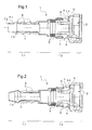
figure 1 est une vue en coupe longitudinale d'un embout conforme à un premier mode de réalisation de l'invention ; - la
figure 2 est une vue analogue à lafigure 1 d'un embout conforme à un deuxième mode de réalisation de l'invention.
- the
figure 1 is a longitudinal sectional view of a mouthpiece conforming to a first mode of embodiment of the invention; - the
figure 2 is a view similar to thefigure 1 of a nozzle according to a second embodiment of the invention.
En référence aux figures, l'embout de raccordement conforme à l'invention est destiné au raccordement d'une canalisation à un élément de circuit de transport de fluide. L'élément est émetteur ou récepteur de fluide et peut être une autre canalisation, un distributeur, une pompe, un réservoir, un actionneur, un injecteur... et comporte ici un embout mâle destiné à être engagé dans l'embout de raccordement conforme à l'invention.With reference to the figures, the connection piece according to the invention is intended for connecting a pipe to a fluid transport circuit element. The element is a transmitter or fluid receiver and can be another pipe, a distributor, a pump, a tank, an actuator, an injector ... and here comprises a male end intended to be engaged in the compliant connection piece. to the invention.
L'embout de raccordement comprend un corps métallique tubulaire, généralement désigné en 1, ayant une première portion d'extrémité 1.1 agencée pour être introduite dans la canalisation et une deuxième portion d'extrémité 1.2 reliée à des moyens, généralement désignés en 2, de connexion à l'élément. La deuxième portion d'extrémité 1.2 est étagée et comprend un tronçon d'entrée, un tronçon central et un tronçon terminal de diamètres décroissants. Le corps métallique est ici en acier mais peut être dans un autre métal. Ce corps est réalisé par un procédé de formage, ici de préférence, par emboutissage profond d'une feuille métallique ou par hydroformage.The connection piece comprises a tubular metal body, generally designated 1, having a first end portion 1.1 arranged to be introduced into the pipe and a second end portion 1.2 connected to means, generally designated 2, of connection to the element. The second end portion 1.2 is stepped and comprises an inlet section, a central section and a terminal section of decreasing diameters. The metal body is here steel but can be in another metal. This body is made by a forming method, preferably here, by deep drawing of a metal sheet or by hydroforming.
Les moyens de connexion 2 sont agencés pour coopérer avec l'embout mâle de l'élément de circuit et sont logés dans une douille 3 en matière plastique rapportée sur la deuxième portion d'extrémité 1.2 du corps métallique 1. La douille 3 comporte une première section engagée dans le tronçon d'entrée et fixée dans celui-ci par encliquetage, la première section comportant des redans 4 en saillie externe qui sont engagés dans des lumières 5 ménagées en correspondance dans le tronçon d'entrée. La douille 3 comporte un deuxième segment s'étendant en saillie à l'extérieur du tronçon d'entrée qui est pourvu d'un verrou mobile radialement entre une position en saillie dans la douille pour accrocher une collerette externe de l'embout mâle et une position escamotée de libération de l'embout mâle. Le verrou est rappelé élastiquement dans la position en saillie. Le tronçon intermédiaire reçoit des éléments d'étanchéité 6, de forme torique, qui ont un diamètre externe légèrement plus grand que le diamètre interne du tronçon intermédiaire et un diamètre interne légèrement inférieur au diamètre externe de l'embout mâle. Le tronçon terminal a un diamètre interne légèrement supérieur au diamètre externe de l'embout mâle et se termine par un épaulement formant une butée à l'enfoncement de l'embout mâle dans la deuxième portion d'extrémité 1.2 du corps métallique 1. Les moyens de connexion 2 sont par exemple conformes à ceux décrits dans le document
Conformément à l'invention, au moins un corps en matière plastique 7 est surmoulé sur au moins une partie externe de la première portion d'extrémité 1.2 du corps métallique 1. Le corps en matière plastique 5 comporte extérieurement au moins un relief 8 à arête vive pour former un relief d'accrochage de la canalisation.According to the invention, at least one
Le corps en matière plastique 7 comporte ici une pluralité de reliefs 8 qui sont de forme annulaire avec un profil en dent de sapin présentant une arête annulaire vive pour mordre dans la paroi interne de la canalisation.The
Le corps en matière plastique 7 est réalisé par surmoulage en injectant la matière plastique à l'état liquide dans un moule dans lequel a été placée la première portion d'extrémité 1.1 du corps métallique 1.The
Le corps en matière plastique 7 et la douille 3 sont par exemple en polyamide chargé ou non.The
En référence à la
Dans ce mode de réalisation, la première portion d'extrémité 1.1 se termine par un collet 1.3 en saillie radiale dans le corps en matière plastique 7. Ceci permet d'éviter d'avoir une ligne de recollement. Dans le procédé de surmoulage, la matière plastique à l'état liquide tend à se répandre dans l'empreinte du moule selon une direction axiale du cors métallique 1 avant de faire le tour du corps métallique 1 en formant le long de celui-ci une ligne de recollement légèrement en creux susceptible d'engendrer un risque de fuite. Le collet 1.3 perturbe l'écoulement axial de la matière plastique en forçant celle-ci à entourer d'abord le corps métallique 1 avant de progresser le long de celui-ci tout en l'enveloppant. Il n'y a donc pas de ligne de recollement. Le collet 1.3 améliore également la résistance de la retenue du corps en matière plastique 7 sur le corps métallique 1.In this embodiment, the first end portion 1.1 ends with a flange 1.3 projecting radially in the
En référence à la
Le bourrelet a un diamètre externe tel qu'il est en contact avec la surface intérieure de la canalisation pour exercer une contrainte d'étanchéité. Ceci permet d'éviter un risque de fuite le long du plan de joint qui s'étend ici selon une direction longitudinale du corps en matière plastique 7.The bead has an outer diameter such that it is in contact with the inner surface of the pipe to exert a sealing stress. This makes it possible to avoid a risk of leakage along the plane of the joint which here extends in a longitudinal direction of the
Le bourrelet améliore également la résistance de la retenue du corps en matière plastique 7 sur le corps métallique 1.The bead also improves the resistance of the
Bien entendu, l'invention n'est pas limitée aux modes de réalisation décrits mais englobe toute variante entrant dans le champ de l'invention telle que définie par les revendications.Of course, the invention is not limited to the embodiments described but encompasses any variant within the scope of the invention as defined by the claims.
En particulier, les moyens de connexion peuvent avoir une structure différente de celle décrite et comporter par exemple une rondelle dentée élastiquement déformable éventuellement associée avec un poussoir de déconnexion.In particular, the connection means may have a different structure from that described and comprise for example an elastically deformable toothed washer possibly associated with a disconnection pusher.
Les moyens de connexion peuvent en outre être logés directement dans le corps métallique.The connection means can also be housed directly in the metal body.
Le corps métallique peut être réalisé par d'autres procédés de formage ou de déformation plastique que l'hydroformage ou l'emboutissage, comme par exemple le fluotournage ou le roulage.The metal body can be made by other methods of forming or plastic deformation than hydroforming or stamping, such as spinning or rolling.
Claims (11)
Applications Claiming Priority (1)
| Application Number | Priority Date | Filing Date | Title |
|---|---|---|---|
| FR1158238A FR2980256B1 (en) | 2011-09-15 | 2011-09-15 | OVERMOLD TIP FOR CONNECTING A PIPE TO AN ELEMENT OF A FLUID TRANSPORT CIRCUIT |
Publications (2)
| Publication Number | Publication Date |
|---|---|
| EP2570710A1 true EP2570710A1 (en) | 2013-03-20 |
| EP2570710B1 EP2570710B1 (en) | 2016-03-09 |
Family
ID=46800130
Family Applications (1)
| Application Number | Title | Priority Date | Filing Date |
|---|---|---|---|
| EP12184274.4A Active EP2570710B1 (en) | 2011-09-15 | 2012-09-13 | Umgossener Trichter zur Verbindung einer Kanalisation mit einem Element eines Flüssigkeitstransportkreislaufs |
Country Status (2)
| Country | Link |
|---|---|
| EP (1) | EP2570710B1 (en) |
| FR (1) | FR2980256B1 (en) |
Cited By (1)
| Publication number | Priority date | Publication date | Assignee | Title |
|---|---|---|---|---|
| DE102016111194A1 (en) | 2016-06-20 | 2017-12-21 | Voss Automotive Gmbh | Coupling part for a connector for the production of hose and / or pipe connections and connectors with such a coupling part |
Citations (4)
| Publication number | Priority date | Publication date | Assignee | Title |
|---|---|---|---|---|
| WO1996007045A1 (en) * | 1994-08-31 | 1996-03-07 | Itt Automotive, Inc. | Pipe joining construction |
| JP2003247684A (en) * | 2002-02-21 | 2003-09-05 | Sanoh Industrial Co Ltd | Connection structure for metal tube ends |
| US20040020533A1 (en) * | 2002-08-02 | 2004-02-05 | Brian Engle | Low permeation weldable fuel tank valve |
| EP1427960A2 (en) | 2001-09-20 | 2004-06-16 | Legris Sa | Connecting device with secure mounting |
-
2011
- 2011-09-15 FR FR1158238A patent/FR2980256B1/en active Active
-
2012
- 2012-09-13 EP EP12184274.4A patent/EP2570710B1/en active Active
Patent Citations (4)
| Publication number | Priority date | Publication date | Assignee | Title |
|---|---|---|---|---|
| WO1996007045A1 (en) * | 1994-08-31 | 1996-03-07 | Itt Automotive, Inc. | Pipe joining construction |
| EP1427960A2 (en) | 2001-09-20 | 2004-06-16 | Legris Sa | Connecting device with secure mounting |
| JP2003247684A (en) * | 2002-02-21 | 2003-09-05 | Sanoh Industrial Co Ltd | Connection structure for metal tube ends |
| US20040020533A1 (en) * | 2002-08-02 | 2004-02-05 | Brian Engle | Low permeation weldable fuel tank valve |
Cited By (2)
| Publication number | Priority date | Publication date | Assignee | Title |
|---|---|---|---|---|
| DE102016111194A1 (en) | 2016-06-20 | 2017-12-21 | Voss Automotive Gmbh | Coupling part for a connector for the production of hose and / or pipe connections and connectors with such a coupling part |
| EP3270028A2 (en) | 2016-06-20 | 2018-01-17 | Voss Automotive GmbH | Coupling part for a plug connector for making tube and/or pipe connections and plug connector having such a coupling part |
Also Published As
| Publication number | Publication date |
|---|---|
| FR2980256A1 (en) | 2013-03-22 |
| EP2570710B1 (en) | 2016-03-09 |
| FR2980256B1 (en) | 2014-07-18 |
Similar Documents
| Publication | Publication Date | Title |
|---|---|---|
| EP1967773B1 (en) | Y-Seal, method of manufacturing such a seal and its use to reduce the forces for fitting a connector | |
| FR2806959A1 (en) | Vehicle fuel tank with wall(s) made of thermoplastic, includes over molded insert(s) for mounting device within tank | |
| EP1493958B1 (en) | Annular seal for fluid transfer connector and connector equiped with such a seal | |
| FR2738893A1 (en) | METHOD OF MAKING A BIT, TIP AND CONNECTOR PRODUCED BY THIS METHOD AND CIRCUIT COMPRISING SUCH A CONNECTOR | |
| FR2789610A1 (en) | PROCESS FOR MANUFACTURING A COMMON RAMP | |
| FR2844011A1 (en) | Common fuel feed pipe for Diesel engine has main duct and branches cold-worked to reduce stress concentrations | |
| FR2882419A1 (en) | PIPE FOR TRANSPORTING A FLUID AND PROCESS FOR PRODUCING THE SAME | |
| EP2570710B1 (en) | Umgossener Trichter zur Verbindung einer Kanalisation mit einem Element eines Flüssigkeitstransportkreislaufs | |
| FR3069478A1 (en) | METHOD FOR MANUFACTURING PLASTIC CONDUIT SUBJECTED TO INTERNAL RELATIVE PRESSURE AND ASSOCIATED CONDUIT | |
| FR2894011A1 (en) | Fluid transfer channel`s flexible pipe end and rigid tube end connecting system for automobile field, has tooth presenting right section for opposing rotation between rigid tube and flexible pipe after being assembled with each other | |
| FR2922475A1 (en) | Fluid e.g. cooling fluid, passages connecting device manufacturing method for motor vehicle, involves over-molding ring on body of connecting device by injecting elastomer thermoplastic material of joint from exterior of body via opening | |
| EP2146128B1 (en) | Hose for an automobile air-conditioning or power-steering circuit | |
| FR2818730A1 (en) | Female sleeve for coupler used e.g. in vehicle pressure fluid distribution has implanted section extended by seals | |
| FR2888306A1 (en) | Flexible tube and connection piece e.g. end piece, joining device, has heat shrinkable sheath type maintenance piece positioned around joining zone of tube and connection piece and shrunk by heating when tube is vulcanized | |
| EP0934485B1 (en) | Method for locking the jointing of a plastic tube on a connecting piece | |
| FR3069306A1 (en) | CONNECTOR FOR FLUID CONNECTION BETWEEN TWO PIPES OR THE LIKE AND ASSOCIATED ARRANGEMENT | |
| FR2952839A1 (en) | Method for mechanically assembling liner in metal tube to manufacture common rail, involves generating deformations required for obtaining assembling of metal tube and metal sleeve by implementing high pressure techniques | |
| JP6639016B2 (en) | Structure of filler pipe inlet | |
| EP2940363B1 (en) | Connection device between the opening of a fluid reservoir and a pipe | |
| WO2017102564A1 (en) | Pyrotechnical igniter | |
| JP5465222B2 (en) | Manufacturing method of resin tube with connector for fuel transportation | |
| FR2886371A1 (en) | Fluid circulation pipe for use in e.g. ventilation system of motor vehicle, has ends delimiting housing receiving sealing device and opening that installs locking unit maintaining fluid transmission or reception unit`s connector inside pipe | |
| FR2786248A1 (en) | Connector for metal conduit supplying fuel to direct injection engine | |
| JPH11108260A (en) | Hose for low pressure piping | |
| US20090256357A1 (en) | Method and joint for sealing |
Legal Events
| Date | Code | Title | Description |
|---|---|---|---|
| PUAI | Public reference made under article 153(3) epc to a published international application that has entered the european phase |
Free format text: ORIGINAL CODE: 0009012 |
|
| AK | Designated contracting states |
Kind code of ref document: A1 Designated state(s): AL AT BE BG CH CY CZ DE DK EE ES FI FR GB GR HR HU IE IS IT LI LT LU LV MC MK MT NL NO PL PT RO RS SE SI SK SM TR |
|
| AX | Request for extension of the european patent |
Extension state: BA ME |
|
| 17P | Request for examination filed |
Effective date: 20130920 |
|
| RBV | Designated contracting states (corrected) |
Designated state(s): AL AT BE BG CH CY CZ DE DK EE ES FI FR GB GR HR HU IE IS IT LI LT LU LV MC MK MT NL NO PL PT RO RS SE SI SK SM TR |
|
| 17Q | First examination report despatched |
Effective date: 20141117 |
|
| GRAP | Despatch of communication of intention to grant a patent |
Free format text: ORIGINAL CODE: EPIDOSNIGR1 |
|
| INTG | Intention to grant announced |
Effective date: 20150907 |
|
| GRAS | Grant fee paid |
Free format text: ORIGINAL CODE: EPIDOSNIGR3 |
|
| GRAA | (expected) grant |
Free format text: ORIGINAL CODE: 0009210 |
|
| AK | Designated contracting states |
Kind code of ref document: B1 Designated state(s): AL AT BE BG CH CY CZ DE DK EE ES FI FR GB GR HR HU IE IS IT LI LT LU LV MC MK MT NL NO PL PT RO RS SE SI SK SM TR |
|
| REG | Reference to a national code |
Ref country code: GB Ref legal event code: FG4D Free format text: NOT ENGLISH |
|
| REG | Reference to a national code |
Ref country code: AT Ref legal event code: REF Ref document number: 779786 Country of ref document: AT Kind code of ref document: T Effective date: 20160315 Ref country code: CH Ref legal event code: EP |
|
| REG | Reference to a national code |
Ref country code: IE Ref legal event code: FG4D Free format text: LANGUAGE OF EP DOCUMENT: FRENCH |
|
| REG | Reference to a national code |
Ref country code: DE Ref legal event code: R096 Ref document number: 602012015355 Country of ref document: DE |
|
| REG | Reference to a national code |
Ref country code: LT Ref legal event code: MG4D |
|
| REG | Reference to a national code |
Ref country code: NL Ref legal event code: MP Effective date: 20160309 |
|
| PG25 | Lapsed in a contracting state [announced via postgrant information from national office to epo] |
Ref country code: ES Free format text: LAPSE BECAUSE OF FAILURE TO SUBMIT A TRANSLATION OF THE DESCRIPTION OR TO PAY THE FEE WITHIN THE PRESCRIBED TIME-LIMIT Effective date: 20160309 Ref country code: GR Free format text: LAPSE BECAUSE OF FAILURE TO SUBMIT A TRANSLATION OF THE DESCRIPTION OR TO PAY THE FEE WITHIN THE PRESCRIBED TIME-LIMIT Effective date: 20160610 Ref country code: HR Free format text: LAPSE BECAUSE OF FAILURE TO SUBMIT A TRANSLATION OF THE DESCRIPTION OR TO PAY THE FEE WITHIN THE PRESCRIBED TIME-LIMIT Effective date: 20160309 Ref country code: FI Free format text: LAPSE BECAUSE OF FAILURE TO SUBMIT A TRANSLATION OF THE DESCRIPTION OR TO PAY THE FEE WITHIN THE PRESCRIBED TIME-LIMIT Effective date: 20160309 Ref country code: NO Free format text: LAPSE BECAUSE OF FAILURE TO SUBMIT A TRANSLATION OF THE DESCRIPTION OR TO PAY THE FEE WITHIN THE PRESCRIBED TIME-LIMIT Effective date: 20160609 |
|
| REG | Reference to a national code |
Ref country code: AT Ref legal event code: MK05 Ref document number: 779786 Country of ref document: AT Kind code of ref document: T Effective date: 20160309 |
|
| PG25 | Lapsed in a contracting state [announced via postgrant information from national office to epo] |
Ref country code: PL Free format text: LAPSE BECAUSE OF FAILURE TO SUBMIT A TRANSLATION OF THE DESCRIPTION OR TO PAY THE FEE WITHIN THE PRESCRIBED TIME-LIMIT Effective date: 20160309 Ref country code: NL Free format text: LAPSE BECAUSE OF FAILURE TO SUBMIT A TRANSLATION OF THE DESCRIPTION OR TO PAY THE FEE WITHIN THE PRESCRIBED TIME-LIMIT Effective date: 20160309 Ref country code: LT Free format text: LAPSE BECAUSE OF FAILURE TO SUBMIT A TRANSLATION OF THE DESCRIPTION OR TO PAY THE FEE WITHIN THE PRESCRIBED TIME-LIMIT Effective date: 20160309 Ref country code: SE Free format text: LAPSE BECAUSE OF FAILURE TO SUBMIT A TRANSLATION OF THE DESCRIPTION OR TO PAY THE FEE WITHIN THE PRESCRIBED TIME-LIMIT Effective date: 20160309 Ref country code: RS Free format text: LAPSE BECAUSE OF FAILURE TO SUBMIT A TRANSLATION OF THE DESCRIPTION OR TO PAY THE FEE WITHIN THE PRESCRIBED TIME-LIMIT Effective date: 20160309 Ref country code: LV Free format text: LAPSE BECAUSE OF FAILURE TO SUBMIT A TRANSLATION OF THE DESCRIPTION OR TO PAY THE FEE WITHIN THE PRESCRIBED TIME-LIMIT Effective date: 20160309 |
|
| REG | Reference to a national code |
Ref country code: FR Ref legal event code: PLFP Year of fee payment: 5 |
|
| PG25 | Lapsed in a contracting state [announced via postgrant information from national office to epo] |
Ref country code: EE Free format text: LAPSE BECAUSE OF FAILURE TO SUBMIT A TRANSLATION OF THE DESCRIPTION OR TO PAY THE FEE WITHIN THE PRESCRIBED TIME-LIMIT Effective date: 20160309 Ref country code: IS Free format text: LAPSE BECAUSE OF FAILURE TO SUBMIT A TRANSLATION OF THE DESCRIPTION OR TO PAY THE FEE WITHIN THE PRESCRIBED TIME-LIMIT Effective date: 20160709 |
|
| PG25 | Lapsed in a contracting state [announced via postgrant information from national office to epo] |
Ref country code: AT Free format text: LAPSE BECAUSE OF FAILURE TO SUBMIT A TRANSLATION OF THE DESCRIPTION OR TO PAY THE FEE WITHIN THE PRESCRIBED TIME-LIMIT Effective date: 20160309 Ref country code: SK Free format text: LAPSE BECAUSE OF FAILURE TO SUBMIT A TRANSLATION OF THE DESCRIPTION OR TO PAY THE FEE WITHIN THE PRESCRIBED TIME-LIMIT Effective date: 20160309 Ref country code: SM Free format text: LAPSE BECAUSE OF FAILURE TO SUBMIT A TRANSLATION OF THE DESCRIPTION OR TO PAY THE FEE WITHIN THE PRESCRIBED TIME-LIMIT Effective date: 20160309 Ref country code: CZ Free format text: LAPSE BECAUSE OF FAILURE TO SUBMIT A TRANSLATION OF THE DESCRIPTION OR TO PAY THE FEE WITHIN THE PRESCRIBED TIME-LIMIT Effective date: 20160309 Ref country code: PT Free format text: LAPSE BECAUSE OF FAILURE TO SUBMIT A TRANSLATION OF THE DESCRIPTION OR TO PAY THE FEE WITHIN THE PRESCRIBED TIME-LIMIT Effective date: 20160711 Ref country code: RO Free format text: LAPSE BECAUSE OF FAILURE TO SUBMIT A TRANSLATION OF THE DESCRIPTION OR TO PAY THE FEE WITHIN THE PRESCRIBED TIME-LIMIT Effective date: 20160309 |
|
| REG | Reference to a national code |
Ref country code: DE Ref legal event code: R097 Ref document number: 602012015355 Country of ref document: DE |
|
| PG25 | Lapsed in a contracting state [announced via postgrant information from national office to epo] |
Ref country code: IT Free format text: LAPSE BECAUSE OF FAILURE TO SUBMIT A TRANSLATION OF THE DESCRIPTION OR TO PAY THE FEE WITHIN THE PRESCRIBED TIME-LIMIT Effective date: 20160309 |
|
| PLBE | No opposition filed within time limit |
Free format text: ORIGINAL CODE: 0009261 |
|
| STAA | Information on the status of an ep patent application or granted ep patent |
Free format text: STATUS: NO OPPOSITION FILED WITHIN TIME LIMIT |
|
| PG25 | Lapsed in a contracting state [announced via postgrant information from national office to epo] |
Ref country code: DK Free format text: LAPSE BECAUSE OF FAILURE TO SUBMIT A TRANSLATION OF THE DESCRIPTION OR TO PAY THE FEE WITHIN THE PRESCRIBED TIME-LIMIT Effective date: 20160309 |
|
| 26N | No opposition filed |
Effective date: 20161212 |
|
| PG25 | Lapsed in a contracting state [announced via postgrant information from national office to epo] |
Ref country code: BE Free format text: LAPSE BECAUSE OF NON-PAYMENT OF DUE FEES Effective date: 20160930 Ref country code: BG Free format text: LAPSE BECAUSE OF FAILURE TO SUBMIT A TRANSLATION OF THE DESCRIPTION OR TO PAY THE FEE WITHIN THE PRESCRIBED TIME-LIMIT Effective date: 20160609 |
|
| PG25 | Lapsed in a contracting state [announced via postgrant information from national office to epo] |
Ref country code: MC Free format text: LAPSE BECAUSE OF FAILURE TO SUBMIT A TRANSLATION OF THE DESCRIPTION OR TO PAY THE FEE WITHIN THE PRESCRIBED TIME-LIMIT Effective date: 20160309 |
|
| REG | Reference to a national code |
Ref country code: CH Ref legal event code: PL |
|
| GBPC | Gb: european patent ceased through non-payment of renewal fee |
Effective date: 20160913 |
|
| PG25 | Lapsed in a contracting state [announced via postgrant information from national office to epo] |
Ref country code: SI Free format text: LAPSE BECAUSE OF FAILURE TO SUBMIT A TRANSLATION OF THE DESCRIPTION OR TO PAY THE FEE WITHIN THE PRESCRIBED TIME-LIMIT Effective date: 20160309 |
|
| REG | Reference to a national code |
Ref country code: IE Ref legal event code: MM4A |
|
| PG25 | Lapsed in a contracting state [announced via postgrant information from national office to epo] |
Ref country code: CH Free format text: LAPSE BECAUSE OF NON-PAYMENT OF DUE FEES Effective date: 20160930 Ref country code: IE Free format text: LAPSE BECAUSE OF NON-PAYMENT OF DUE FEES Effective date: 20160913 Ref country code: GB Free format text: LAPSE BECAUSE OF NON-PAYMENT OF DUE FEES Effective date: 20160913 Ref country code: LI Free format text: LAPSE BECAUSE OF NON-PAYMENT OF DUE FEES Effective date: 20160930 |
|
| PG25 | Lapsed in a contracting state [announced via postgrant information from national office to epo] |
Ref country code: LU Free format text: LAPSE BECAUSE OF NON-PAYMENT OF DUE FEES Effective date: 20160913 |
|
| REG | Reference to a national code |
Ref country code: FR Ref legal event code: PLFP Year of fee payment: 6 |
|
| REG | Reference to a national code |
Ref country code: BE Ref legal event code: MM Effective date: 20160930 |
|
| REG | Reference to a national code |
Ref country code: DE Ref legal event code: R081 Ref document number: 602012015355 Country of ref document: DE Owner name: NORMA AUTOLINE FRANCE SAS, FR Free format text: FORMER OWNER: PARKER HANNIFIN MANUFACTURING FRANCE SAS, ANNEMASSE, FR |
|
| PG25 | Lapsed in a contracting state [announced via postgrant information from national office to epo] |
Ref country code: CY Free format text: LAPSE BECAUSE OF FAILURE TO SUBMIT A TRANSLATION OF THE DESCRIPTION OR TO PAY THE FEE WITHIN THE PRESCRIBED TIME-LIMIT Effective date: 20160309 Ref country code: HU Free format text: LAPSE BECAUSE OF FAILURE TO SUBMIT A TRANSLATION OF THE DESCRIPTION OR TO PAY THE FEE WITHIN THE PRESCRIBED TIME-LIMIT; INVALID AB INITIO Effective date: 20120913 |
|
| PG25 | Lapsed in a contracting state [announced via postgrant information from national office to epo] |
Ref country code: TR Free format text: LAPSE BECAUSE OF FAILURE TO SUBMIT A TRANSLATION OF THE DESCRIPTION OR TO PAY THE FEE WITHIN THE PRESCRIBED TIME-LIMIT Effective date: 20160309 Ref country code: MT Free format text: LAPSE BECAUSE OF FAILURE TO SUBMIT A TRANSLATION OF THE DESCRIPTION OR TO PAY THE FEE WITHIN THE PRESCRIBED TIME-LIMIT Effective date: 20160309 Ref country code: MK Free format text: LAPSE BECAUSE OF FAILURE TO SUBMIT A TRANSLATION OF THE DESCRIPTION OR TO PAY THE FEE WITHIN THE PRESCRIBED TIME-LIMIT Effective date: 20160309 |
|
| REG | Reference to a national code |
Ref country code: FR Ref legal event code: PLFP Year of fee payment: 7 |
|
| PG25 | Lapsed in a contracting state [announced via postgrant information from national office to epo] |
Ref country code: AL Free format text: LAPSE BECAUSE OF FAILURE TO SUBMIT A TRANSLATION OF THE DESCRIPTION OR TO PAY THE FEE WITHIN THE PRESCRIBED TIME-LIMIT Effective date: 20160309 |
|
| PGFP | Annual fee paid to national office [announced via postgrant information from national office to epo] |
Ref country code: FR Payment date: 20230925 Year of fee payment: 12 Ref country code: DE Payment date: 20230927 Year of fee payment: 12 |